

Page 1

Quick Start
Logix5000 Control Systems: Connect Kinetix 350 Drives over
an EtherNet/IP Network
Catalog Numbers Logix5000 Controllers, Kinetix 350 Drives
Page 2
Important User Information
IMPORTANT
Solid-state equipment has operational characteristics differing from those of electromechanical equipment. Safety
Guidelines for the Application, Installation and Maintenance of Solid State Controls (publication SGI-1.1
your local Rockwell Automation
sales office or online at http://www.rockwellautomation.com/literature/) describes
some important differences between solid-state equipment and hard-wired electromechanical devices. Because of this
difference, and also because of the wide variety of uses for solid-state equipment, all persons responsible for applying this
equipment must satisfy themselves that each intended application of this equipment is acceptable.
In no event will Rockwell Automation, Inc. be responsible or liable for indirect or consequential damages resulting from the
use or application of this equipment.
The examples and diagrams in this manual are included solely for illustrative purposes. Because of the many variables and
requirements associated with any particular installation, Rockwell Automation, Inc. cannot assume responsibility or
liability for actual use based on the examples and diagrams.
No patent liability is assumed by Rockwell Automation, Inc. with respect to use of information, circuits, equipment, or
software described in this manual.
Reproduction of the contents of this manual, in whole or in part, without written permission of Rockwell Automation,
Inc., is prohibited.
Throughout this manual, when necessary, we use notes to make you aware of safety considerations.
available from
WARNING: Identifies information about practices or circumstances that can cause an explosion in a hazardous environment,
which may lead to personal injury or death, property damage, or economic loss.
ATTENTION: Identifies information about practices or circumstances that can lead to personal injury or death, property
damage, or economic loss. Attentions help you identify a hazard, avoid a hazard, and recognize the consequence.
SHOCK HAZARD: Labels may be on or inside the equipment, for example, a drive or motor, to alert people that dangerous
voltage may be present.
BURN HAZARD: Labels may be on or inside the equipment, for example, a drive or motor, to alert people that surfaces may
reach dangerous temperatures.
Identifies information that is critical for successful application and understanding of the product.
Allen-Bradley, CompactLogix, Integrated Architecture, Kinetix, Logix5000 , MP-Series, PanelView, POINT I/O, Rockwell Software, Rockwell Automation, R SLogix, Stratix 200 0, and TechConnect are trademarks of
Rockwell Automation , Inc.
Trademarks not belonging to Rockwell Automation are property of their respective companies.
Page 3

Table of Contents
Preface
Prepare the Kinetix 350
Drive Hardware
About This Publication. . . . . . . . . . . . . . . . . . . . . . . . . . . . . . . . . . . . . . . . . . . . 5
Before Using This Publication. . . . . . . . . . . . . . . . . . . . . . . . . . . . . . . . . . . . . . 5
Other Logix5000 Control System Quick Starts . . . . . . . . . . . . . . . . . . . . . . 8
Use Each Chapter . . . . . . . . . . . . . . . . . . . . . . . . . . . . . . . . . . . . . . . . . . . . . . . . . 8
Where to Start . . . . . . . . . . . . . . . . . . . . . . . . . . . . . . . . . . . . . . . . . . . . . . . . . . . . 9
How Hardware is Connected . . . . . . . . . . . . . . . . . . . . . . . . . . . . . . . . . . . . . 10
Required Software. . . . . . . . . . . . . . . . . . . . . . . . . . . . . . . . . . . . . . . . . . . . . . . . 10
Parts List . . . . . . . . . . . . . . . . . . . . . . . . . . . . . . . . . . . . . . . . . . . . . . . . . . . . . . . . 11
Additional Resources . . . . . . . . . . . . . . . . . . . . . . . . . . . . . . . . . . . . . . . . . . . . . 12
Chapter 1
Before You Begin. . . . . . . . . . . . . . . . . . . . . . . . . . . . . . . . . . . . . . . . . . . . . . . . . 13
What You Need. . . . . . . . . . . . . . . . . . . . . . . . . . . . . . . . . . . . . . . . . . . . . . . . . . 14
Follow These Steps . . . . . . . . . . . . . . . . . . . . . . . . . . . . . . . . . . . . . . . . . . . . . . . 15
Prepare the Panel. . . . . . . . . . . . . . . . . . . . . . . . . . . . . . . . . . . . . . . . . . . . . . . . . 16
Mount the Kinetix 350 Drive . . . . . . . . . . . . . . . . . . . . . . . . . . . . . . . . . . . . . 16
Ground the Kinetix 350 Drive . . . . . . . . . . . . . . . . . . . . . . . . . . . . . . . . . . . . 17
Disable the Safe Torque-off Feature. . . . . . . . . . . . . . . . . . . . . . . . . . . . . . . . 18
Wiring Diagram . . . . . . . . . . . . . . . . . . . . . . . . . . . . . . . . . . . . . . . . . . . . . . . . . 19
Wire the IOD Connector. . . . . . . . . . . . . . . . . . . . . . . . . . . . . . . . . . . . . . . . . 20
Wire the Back-up Power Connector . . . . . . . . . . . . . . . . . . . . . . . . . . . . . . . 22
Wire the Input Power Connector . . . . . . . . . . . . . . . . . . . . . . . . . . . . . . . . . 23
Wire the Motor Power Connector. . . . . . . . . . . . . . . . . . . . . . . . . . . . . . . . . 24
Apply the Motor Cable Shield Clamp. . . . . . . . . . . . . . . . . . . . . . . . . . . . . . 25
Wire the Motor Feedback Connector . . . . . . . . . . . . . . . . . . . . . . . . . . . . . 26
Connect the Kinetix 350 Drive to the EtherNet/IP Network . . . . . . . . 27
Assign an IP Address to the Kinetix 350 Drive . . . . . . . . . . . . . . . . . . . . . . 27
Additional Resources . . . . . . . . . . . . . . . . . . . . . . . . . . . . . . . . . . . . . . . . . . . . . 29
Add a Kinetix 350 Drive to an
RSLogix 5000 Project
Index
Chapter 2
Before You Begin. . . . . . . . . . . . . . . . . . . . . . . . . . . . . . . . . . . . . . . . . . . . . . . . . 31
What You Need. . . . . . . . . . . . . . . . . . . . . . . . . . . . . . . . . . . . . . . . . . . . . . . . . . 32
Follow These Steps . . . . . . . . . . . . . . . . . . . . . . . . . . . . . . . . . . . . . . . . . . . . . . . 33
Add the Kinetix 350 Drive to the RSLogix 5000 Project. . . . . . . . . . . . . 34
Configure the Motion Group . . . . . . . . . . . . . . . . . . . . . . . . . . . . . . . . . . . . . 37
Configure Axis Properties. . . . . . . . . . . . . . . . . . . . . . . . . . . . . . . . . . . . . . . . . 39
Apply Power to the Kinetix 350 Drive System . . . . . . . . . . . . . . . . . . . . . . 41
Test the Axis. . . . . . . . . . . . . . . . . . . . . . . . . . . . . . . . . . . . . . . . . . . . . . . . . . . . . 44
Tune an Axis. . . . . . . . . . . . . . . . . . . . . . . . . . . . . . . . . . . . . . . . . . . . . . . . . . . . . 46
Additional Resources . . . . . . . . . . . . . . . . . . . . . . . . . . . . . . . . . . . . . . . . . . . . . 46
. . . . . . . . . . . . . . . . . . . . . . . . . . . . . . . . . . . . . . . . . . . . . . . . . . . . . . . . . . . . . . . . . .47
Rockwell Automation Publication IASIMP-QS032A-EN-P - March 2012 3
Page 4

Table of Contents
Notes:
4 Rockwell Automation Publication IASIMP-QS032A-EN-P - March 2012
Page 5

Preface
IMPORTANT
IMPORTANT
About This Publication
This quick start provides examples and procedures for integrating a Kinetix 350 drive into any
Logix5000
examples are not complex, and offer easy solutions to verify that devices are functioning and
communicating properly.
Before Using This Publication
controllers control system over an EtherNet/IP network. The programming
This publication describes basic example tasks you can complete when using a Kinetix 350 drive over an EtherNet/IP
network. The tasks described are not the only tasks you can complete with the drive on an EtherNet/IP network. You
will likely need to complete additional tasks when using a Kinetix 350 drive in a specific Logix5000 control system.
You can only complete the tasks described in this publication after first completing some
prequisite tasks with a Logix5000 controller. For example, before you can add a Kinetix 350
drive to an RSLogix
5000 project, as described on page 31, you must first create the project in a
Logix5000 controller.
The example graphics shown in Table 1 - Required Tasks to Complete before Using This Quick Start on page 6 are for
CompactLogix 5370 L3 controllers. Depending on the Logix5000 controller you are using, the specific steps to
complete the tasks described in the table might vary.
For more information on how to complete these tasks with specific Logix5000 controllers, see
the Integrated Architecture
publication IASIMP-QR024
: Logix5000 Control Systems Quick Starts Quick Reference,
.
Rockwell Automation Publication IASIMP-QS032A-EN-P - March 2012 5
Page 6
Preface
Table 1 - Required Tasks to Complete before Using This Quick Start
Task Description
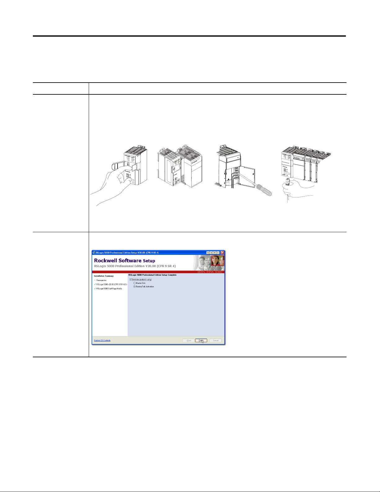
Prepare the Logix5000
control system
hardware
Assemble the control system and connect to necessary communication networks. Some components, for
example, the Logix5000 controller and system power supply, are required. Other components, for example, a
network communication module, are optional.
These example graphics show the assembly of one Logix5000 controller.
1 (Front)
2 (Rear)
IMPORTANT: This task does not include installation of specific hardware components, for example,
Kinetix 350 drives, used over the networks included in your application.
Prepare the computer Install necessary software on your complete. Some software, for example, RSLogix 5000 software.
6 Rockwell Automation Publication IASIMP-QS032A-EN-P - March 2012
Page 7
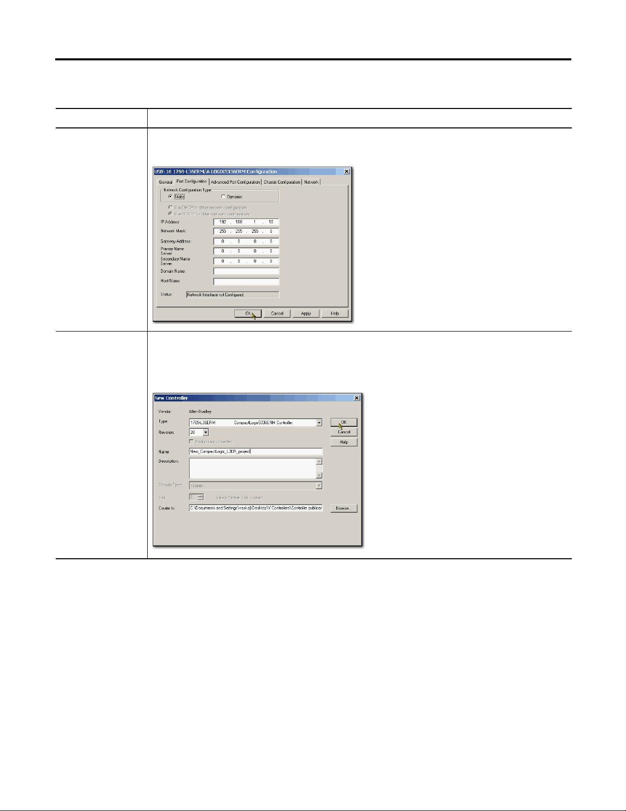
Table 1 - Required Tasks to Complete before Using This Quick Start
Task Description
Preface
Configure the
networks
Create an
RSLogix 5000 project
Complete required tasks associated with the networks used in your application, such as assigning an IP address
to the controller’s communication port or communication module in your Logix5000 control system.
Create a project to be used with your Logix5000 controller. A project includes all desired control system
components and necessary programming. For example, add ladder logic to test tasks associated with individual
system components.
Rockwell Automation Publication IASIMP-QS032A-EN-P - March 2012 7
Page 8

Preface
Other Logix5000 Control System Quick Starts
This quick start describes how to use one device on one network in a Logix5000 control system.
Typically, though, a Logix5000 control system includes more than the controller and one device
on one network.
For example, if a Logix5000 control system operates on an EtherNet/IP network, in addition to
a controller, power supply, and communication modules, the system might use remote I/O
modules, drives, and HMI terminals.
Other quick starts describe how to use different devices on different networks in Logix5000
control systems. For more information, see the Integrated Architecture: Logix5000 Control
Systems Quick Starts Quick Reference, publication IASIMP-QR024
.
Use Each Chapter
The beginning of each chapter contains the following information. You should read these
sections before beginning work in each chapter:
• Before You Begin - This section lists the tasks you must complete before starting
the chapter.
• What You Need - This section lists the tools that are required to complete the tasks in
the chapter.
• Follow These Steps - This section illustrates the steps in the current chapter.
8 Rockwell Automation Publication IASIMP-QS032A-EN-P - March 2012
Page 9
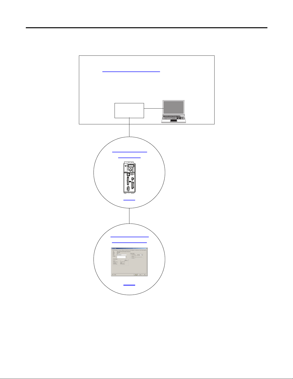
Where to Start
Prepare the Kinetix 350
Drive Hardware
page 13
Prerequisite Tasks
Described in Before Using This Publication
on page 5.
1. Prepare the Logix5000 control system hardware
2. Prepare the computer
3. Configure the networks
4. Create an RSLogix 5000 project
Logix5000
Control ler
Add a Kinetix 350 Drive to
an RSLogix 5000 Project
page 31
Preface
Rockwell Automation Publication IASIMP-QS032A-EN-P - March 2012 9
Page 10
Preface
IMPORTANT
2
3
5
4
1
R
W
P
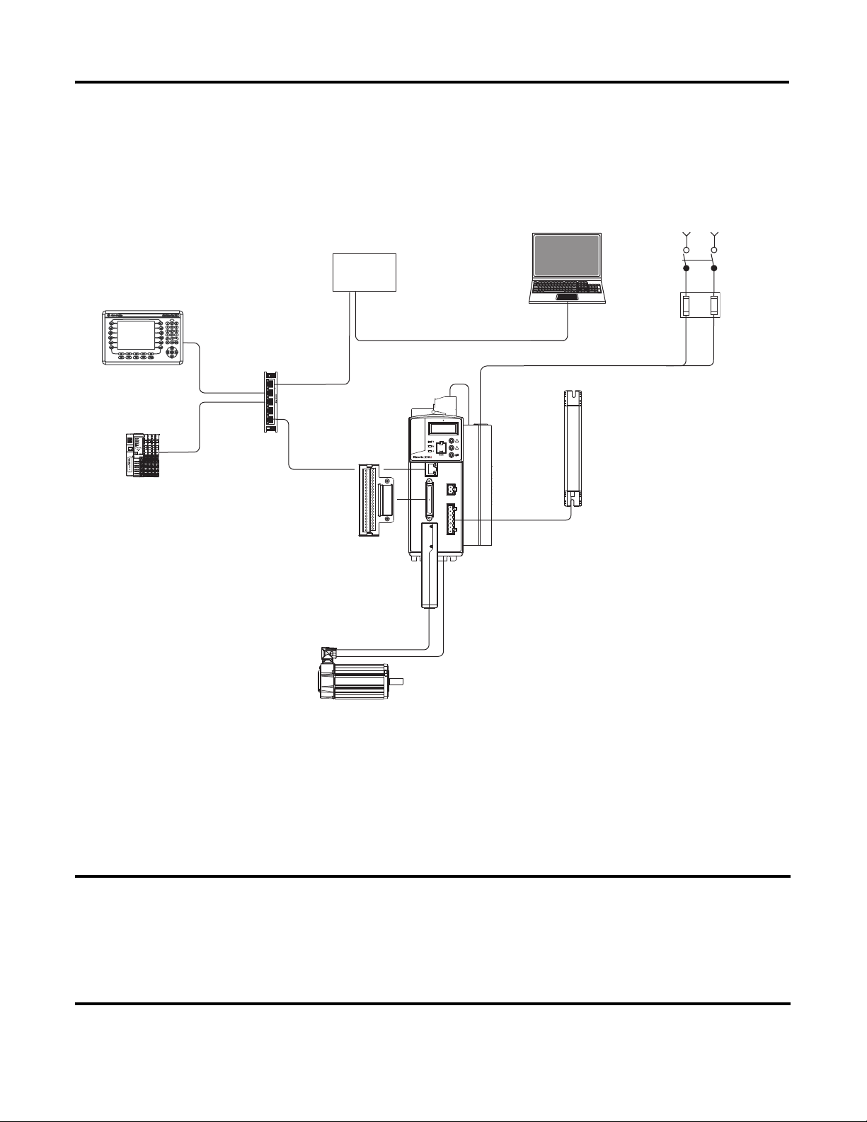
Logix5000
Controller
Stratix 2000
Switch
Computer with
RSLogix 5000 Software
MP-Series
Rotary Motor
Single-phase Input Power
Shunt
Resistor
Motor Feedback Cable
Kinetix 350
Drive
Terminal Expansion Block
1734 POINT I/O
Modules
Pane lView
Plus Terminal
AC Line Filter
How Hardware is Connected
This graphic shows an example control system that uses a Kinetix 350 drive.
Required Software
To complete examples in this quick start, you need RSLogix 5000 software. RSLogix 5000
software is required to create or change RSLogix 5000 projects that use Kinetix 350 drives.
This quick start uses RSLogix 5000 software, version 20.00.00 or later, because the example Logix5000 controller, and
associated tasks, described herein are completed in a CompactLogix 5370 L3 control system. CompactLogix 5370 L3
control systems require RSLogix 5000 software, version 20.00.00 or later.
If you connect a Kinetix 350 drive over an EtherNet/IP network in a Logix5000 control system that uses a different
Logix 5000 controller, the minimum version may differ.
10 Rockwell Automation Publication IASIMP-QS032A-EN-P - March 2012
Page 11

Parts List
You need these parts to complete the tasks described in this quick start.
Preface
Quantity Cat. No. Description
1 2097-V31PR2-LM Kinetix 350 Single Axis Ethernet/IP Servo Drive
1 MPL-A310P-MJ72AA MP-Series Low-inertia Servo Motor
1 The connectors required to
1 6-pin Motor Power (MP) Connector
1 24V DC Back-up Power (BP) Connector
1 4- pin General-purpose AC Input Power (IPD) Connector
1 2097-TB1 Bulletin 2097 I/O Terminal Expansion Block - 50-pin SCSI I/O (IOD) Connector
1 2090-CPWM7DF-16AA03 6-pin Standard Power Cable with SpeedTec DIN Connector Type 923
1 2090-CFBM7DD-CEAA03 Standard Feedback Cable with SpeedTec DIN Connector Type 623
1 1585J-M8PBJM-2 RJ45 to RJ45 patchcord Ethernet cables
3 Jumper wires
use Kinetix 350 drives vary
by drive catalog number.
The specific connectors to
be used with your
2097-V31PR2-LM drive
ship with the drive.
You do not need to order
this part separately.
6-pin Safe Torque Off (STO) Connector
For a list of parts required to complete the prerequisite tasks listed in Tab le 1 -
Required Tasks to
Complete before Using This Quick Start on page 6, see the documentation describing those
tasks.
Rockwell Automation Publication IASIMP-QS032A-EN-P - March 2012 11
Page 12

Preface
Additional Resources
Resource Description
Kinetix 350 Single-axis EtherNet/IP Servo Drives User
Manual, publication 2097-UM002
Kinetix 350 Single-axis EtherNet/IP Servo Drives
Installation Instructions, publication 2097-IN008
EtherNet/IP Modules in Logix5000 Control Systems,
publication ENET-UM001
Industrial Automation Wiring and Grounding Guidelines,
publication 1770-4.1
Product Certifications website, http://www.ab.com Provides declarations of conformity, certificates, and other certification
Describes how to install, wire, configure, operate, and troubleshoot your
Kinetix 350 drive.
Describes how to install and wire your Kinetix 350 drive.
Describes how to install, configure, and operate EtherNet/IP modules.
Provides general guidelines for installing a Rockwell Automation industrial
system.
details.
You can view or download publications at http://www.rockwellautomation.com/literature/. To
order paper copies of technical documentation, contact your local Allen-Bradley
distributor or
Rockwell Automation sales representative.
12 Rockwell Automation Publication IASIMP-QS032A-EN-P - March 2012
Page 13

Chapter
Prepare the Kinetix 350 Drive Hardware
In this chapter, you learn how to complete the following tasks:
• Mount a 2097-V31PR2-LM drive.
• Make multiple connections, for example, power, feedback and resistor connections to
the drive.
• Configure EtherNet/IP communication for the drive.
1
Before You Begin
You must complete these tasks described in Before Using This Publication on page 5 before using
this chapter:
• Prepare the Logix5000 control system hardware
• Prepare the computer
• Configure the networks - The tasks described in this chapter require an
EtherNet/IP network.
• Create an RSLogix 5000 project
The example RSLogix 5000 project used in this chapter uses a
CompactLogix 5370 L3 controller.
Rockwell Automation Publication IASIMP-QS032A-EN-P - March 2012 13
Page 14

Chapter 1 Prepare the Kinetix 350 Drive Hardware
What You Need
This table lists the products you need to complete the tasks described in this chapter.
Quantity Cat. No. Description
1 2097-V31PR2-LM Kinetix 350 Single Axis Ethernet/IP Servo Drive
1 MPL-A310P-MJ72AA MP-Series Low-inertia Servo Motor
1 The connectors required to
1 6-pin Motor Power (MP) Connector
1 24V DC Back-up Power (BP) Connector
1 4- pin General-purpose AC Input Power (IPD) Connector
1 2097-TB1 Bulletin 2097 I/O Terminal Expansion Block - 50-pin SCSI I/O (IOD) Connector
1 2090-CPWM7DF-16AA03 6-pin Standard Power Cable with SpeedTec DIN Connector Type 923
1 2090-CFBM7DD-CEAA03 Standard Feedback Cable with SpeedTec DIN Connector Type 623
1 1585J-M8PBJM-2 RJ45 to RJ45 patchcord Ethernet cables
3 Jumper wires
use Kinetix 350 drives vary
by drive catalog number.
The specific connectors to
be used with your
2097-V31PR2-LM drive
ship with the drive.
You do not need to order
this part separately.
6-pin Safe Torque Off (STO) Connector
14 Rockwell Automation Publication IASIMP-QS032A-EN-P - March 2012
Page 15
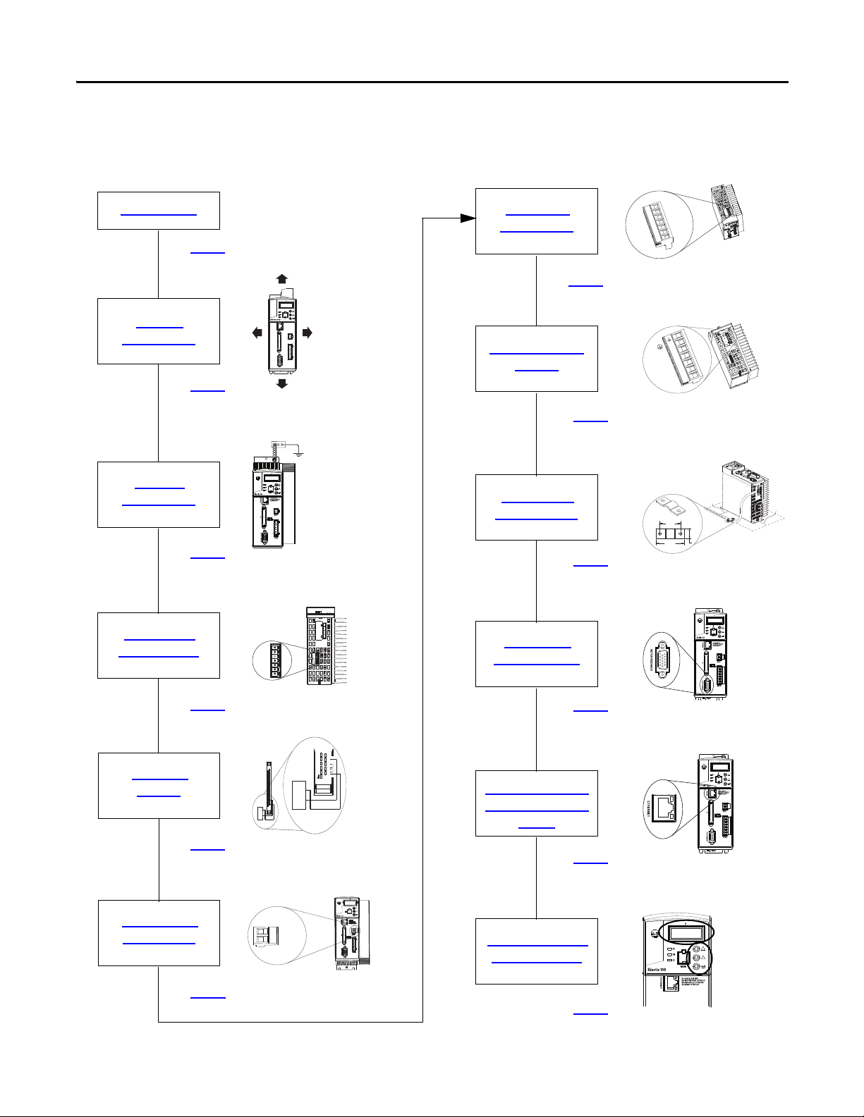
Follow These Steps
Prepare the Panel
Ground the
Kinetix 350 Drive
page 16
page 17
Mount the
Kinetix 350 Drive
page 17
Apply the Motor
Cable Shield Clamp
page 25
Wire the Motor
Feedback Connector
page 26
Connect the Kinetix 350
Drive to the EtherNet/IP
Network
page 27
Disable the Safe
Torque-off Feature
page 18
Wire the Motor Power
Conne ctor
page 24
Assign an IP Address to
the Kinetix 350 Drive
page 27
Wire the IOD
Conne ctor
page 20
Pin 26
Pin 25
Pin 46
Pin 47
Pin 48
Pin 49
Pin 50
Pin 29
Pin 28
Pin 27
+
-
Wire the Back- up
Power Connector
page 22
Wire the Input
Power Connector
page 23
Prepare the Kinetix 350 Drive Hardware Chapter 1
1 2 3 4 5 6
STO
PE
W
W
V
V
U
U
+
+24V DC
24
-24V DC
-
Rockwell Automation Publication IASIMP-QS032A-EN-P - March 2012 15
Page 16
Chapter 1 Prepare the Kinetix 350 Drive Hardware
25.0 mm (1.0 in.)
3 mm (0.12 in.)
3 mm (0.12 in.)
25.0 mm (1.0 in.)
Prepare the Panel
You must install the 2097-V31PR2-LM drive on a grounded panel. This quick start assumes you
installed a panel when you fulfilled the prerequisite task of installing the Logix5000 control
system hardware:
• If you have already installed a painted, grounded panel, move to section Mount the Kinetix
350 Drive.
• If you have not already installed a painted, grounded panel, do so before proceeding to the
next section.
For more information on properly installing a panel that you can use with a Kinetix 350
drive, see the Kinetix 350 Single-axis EtherNet/IP Servo Drives User Manual,
publication 2097-UM002
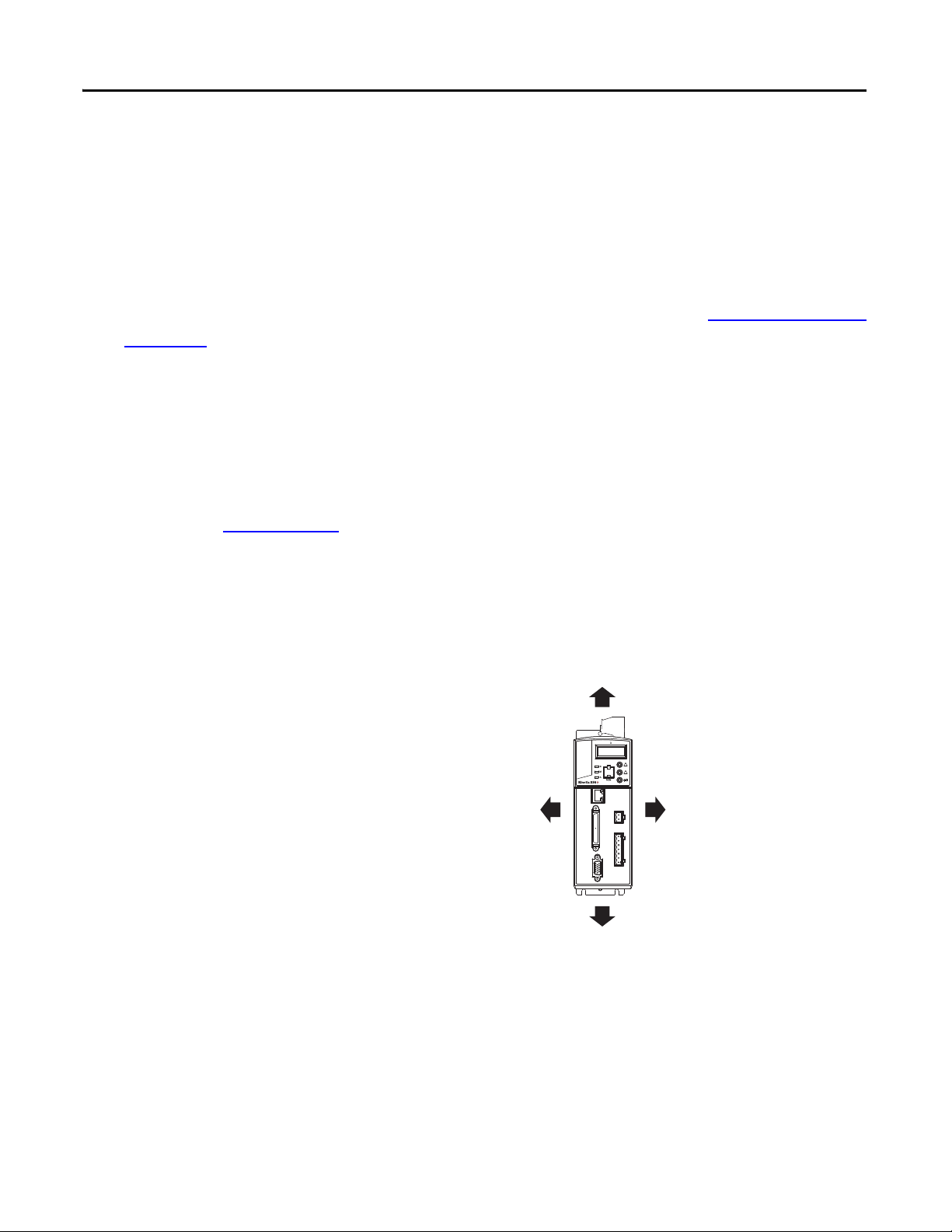
Mount the Kinetix 350 Drive
1. Verify that you have at least the
minimum clearance to mount your
2097-V31PR2-LM drive on
the panel.
.
16 Rockwell Automation Publication IASIMP-QS032A-EN-P - March 2012
Page 17

Prepare the Kinetix 350 Drive Hardware Chapter 1
238 mm
(9.37 in.)
Additional clearance below the
connector kit is necessary to
provide the recommended
cable bend radius.
Dimensions are in mm (in.)
Braided Ground Strap Bonded Cabinet Ground Bus
Ground Grid or Power
Distribution Ground
Ground Stud
2. Use the dimensions shown to make sure your mounting holes are in the correct location.
A
5.0
(0.19)
238
(9.37)
7.1
(0.28)
9.7
(0.38)
6.6
(0.26)
11.8
(0.46)
30.8
(1.21)
38.1
(1.5)
182
(7.18)
190
(7.50)
Ø 4.57
(0.18) 3x
B
3. Attach the drive to the cabinet using M4 (#6-32) steel machine screws torqued to 1.1 N
(9.8 lb
in) beginning with the upper mounting slots and then the lower slots.
4. Tighten all mounting fasteners.
Ground the Kinetix 350 Drive
Use a braided ground strap or 4.0 mm2
(12 AWG) solid copper wire 100 mm
(3.9 in.) long to ground the
2097-V31PR2-LM drive to the bonded
cabinet ground bus, as shown.
Rockwell Automation Publication IASIMP-QS032A-EN-P - March 2012 17
m
Page 18

Chapter 1 Prepare the Kinetix 350 Drive Hardware
IMPORTANT
1 2 3 4 5 6
STO
Safe Torque-off
(STO) Connector
Bottom View of Drive
STO-1
STO-2
STO-3
STO-4
STO-5
STO-6
Motion-allowed
Jumpers
Disable the Safe Torque-off Feature
The safe torque-off feature is used in applications used in safety conditions. This feature safely
removes power from the gate firing circuits of the drives output power devices (IGBTs). The
feature is enabled by default when the Kinetix 350 drive ships from the factory.
If your application, for example, the one used in this quick start, does not require the use of safety
options, you disable the safe torque-off feature. You use jumper wires, as shown, to disable the
safe torque-off feature. The tasks in this quick start are not completed in an environment that
includes safety conditions. You can disable the safe torque-off feature.
Complete these steps to disable the safe torque-off feature.
1. Remove the STO connector from
the drive.
2. Install STO Motion-allowed
jumpers at the termination points
as shown.
3. Insert the STO connector into the
bottom of the drive.
For more information about
using the safe torque-off
feature in an environment
that includes safety
conditions, see the Kinetix
350 Single-axis EtherNet/IP
Servo Drive User Manual,
publication 2097-UM002.
18 Rockwell Automation Publication IASIMP-QS032A-EN-P - March 2012
Page 19

Prepare the Kinetix 350 Drive Hardware Chapter 1
IMPORTANT
Bonded Cabinet
Ground Bus
Single-phase AC
Input 120V rms AC,
50/60 Hz
User-supplied
+24V DC
Main Single-phase
AC Input (IPD)
Connector
Back-up Power
(BP) Connector
Motor Power
(MP) Connector
Ground Stud
L2/N
L1
Contactor
Coil
Input
Fusing
Fuse
Disconnect
or Circuit
Breakers
Cable Shield
Clamp
AC Line Filter
(Opti onal)
PE
N
L1
L2/N
Pin 26
Pin 29
Pin 27
Pin 28
User-supplied 24V
DC Power Supply
I/O (IOD)
Conne ctor
+
-
Wiring Diagram
You can wire 120V or 240V single-phase input power to your Kinetix 2097-V31PR2-LM drive.
When completing the tasks described in this quick start, you use 120V single-phase power.
The following graphic shows how to wire connectors on your Kinetix 2097-V31PR2-LM drive
for 120V single-phase power. More detailed descriptions of how to wire each connector are
included later in this chapter.
Keep in mind, the following graphic does not show all the possible connections to your
Kinetix 2097-V31PR2-LM drive. It only describes the connections required to complete the tasks
described in this quick start.
For more complete information on how to wire your Kinetix 350 drive see the Kinetix 350 Single-axis
EtherNet/IP Servo Drives User Manual, publication 2097-UM002.
Rockwell Automation Publication IASIMP-QS032A-EN-P - March 2012 19
Page 20

Chapter 1 Prepare the Kinetix 350 Drive Hardware
Wire the IOD Connector
The 2097-V31PR2-LM drive ships from the factory with the drive ENABLE functionality
enabled. In addition to this configuration, you must wire the 2097-TB1 I/O terminal expansion
block to complete the tasks described in this quick start, for example, the tasks described in Your
control system can execute drive actions, such as the Hookup test described on Te st th e Ax is
page 44.
To use your Kinetix drive with the drive ENABLE functionality in the enabled state, you must
connect a user-supplied, external 24V DC power supply to the drive via the IOD connector.
Complete these steps to use the IOD connector.
1. Verify the user-supplied, external power supply is not powered.
on
2. Connect a wire from a -24V DC terminal on the external power supply to pin 26 (+/-
Overtravel, enable and home common) on the IOD connector.
3. Jumper a wire from pin 27 (Negative hardware overtravel) to pin 28 (Positive hardware
overtravel) on the IOD connector.
4. Jumper a wire from pin 28 (Positive hardware overtravel) to pin 29 (Drive enable) on the
IOD connector.
20 Rockwell Automation Publication IASIMP-QS032A-EN-P - March 2012
Page 21

Prepare the Kinetix 350 Drive Hardware Chapter 1
IMPORTANT
Pin 26
Pin 25
Pin 46
Pin 47
Pin 48
Pin 49
Pin 50
Pin 29
Pin 28
Pin 27
+
-
User-supplied
24V DC Power
Supply
I/O Connection
5. Connect a wire from a +24V DC terminal on the external power supply to pin 29
(ENABLE signal) on the IOD connector.
6. Insert the IOD connector into the
drive in the location shown in this
graphic.
Do not connect power to the
external power supply.
Rockwell Automation Publication IASIMP-QS032A-EN-P - March 2012 21
Page 22

Chapter 1 Prepare the Kinetix 350 Drive Hardware
IMPORTANT
Wire the Back-up Power Connector
You need a user-supplied, external 24V DC power supply to provide back-up power to the drive.
Complete these steps to wire the BP connector.
1. Verify the user-supplied, external power supply is not powered.
2. Remove the BP connector from
the drive.
3. Remove approximately 6 mm (0.25
in.) insulation from two 1.5 mm
(16 AWG) copper wires.
2
+
24
-
+24V DC
-24V DC
4. Connect a wire from a +24V DC
terminal on the external power
supply to the +24V DC terminal
on the BP connector.
5. Connect a wire from a -24C DC terminal on the external power supply to the -24V DC
terminal on the BP connector.
6. Insert the connector plug into the drive in the location shown above.
Do not connect power to the external power supply.
22 Rockwell Automation Publication IASIMP-QS032A-EN-P - March 2012
Page 23

Prepare the Kinetix 350 Drive Hardware Chapter 1
IMPORTANT
L2/N
L1
N
PE
Top View of Drive
Wire the Input Power Connector
You can use a 120V AC or 240V DC power source to connect input power to the
2097-V31PR2-LM drive via the IPD connector. In this quick start, we describe how to connect a
120V AC power source to the drive.
Complete these steps to wire the IPD connector.
1. Verify the 120V AC power source is not powered.
2. Remove the IPD connector plug
from the top of the drive.
3. Remove approximately 7 mm
(0.28 in.) insulation from four
2
2.5 mm
copper wires.
(14 AWG)
4. Insert the wires from the 120V
AC power source cable into the
IPD connector positions
according to the following table.
Power Cable Wire Terminal
Black L1
White N
Green PE
The L2/N connector is not used when connecting input power from a 120V AC
power source.
5. Insert the connector plug into the location shown above.
Do not connect power to the external power supply.
Rockwell Automation Publication IASIMP-QS032A-EN-P - March 2012 23
Page 24

Chapter 1 Prepare the Kinetix 350 Drive Hardware
Bottom View of Drive
Wire the Motor Power Connector
This publication uses a 2090-CPWM7DF-16AA03 standard power cable with SpeedTec DIN
connector type 923 to wire power from the 2097-V31PR2-LM drive to the motor.
Complete these steps to wire the power cable to the MP connector.
1. Remove the MP connector from the bottom of the drive.
2. Remove approximately 7 mm
(0.28 in.) insulation from four
2
2.5 mm
copper wires.
3. Insert the wires into the
appropriate connector positions
according to the following table.
MP-Series Servo
Motor Wire
(14 AWG)
Terminal
PE
W
W
V
V
U
U
Green/
yellow
W/Blue W
V/Black V
U/Brown U
PE
4. Insert the MP connector into the module as shown above.
5. Connect the other end of the 2090-CPWM7DF-16AA03 cable to the motor.
24 Rockwell Automation Publication IASIMP-QS032A-EN-P - March 2012
Page 25

Prepare the Kinetix 350 Drive Hardware Chapter 1
25 mm
(1.0) in.
If panel is painted, remove paint to
provide metal-to-metal contact.
34 mm
(1.34) in.
Motor Power Ground Shield Clamp
12.7 mm
(0.50) in.
50…75 mm
(2…3 in.)
50…75 mm
(2…3 in.)
Apply the Motor Cable Shield Clamp
Complete these steps to apply the motor cable shield clamp.
1. Locate a position for installing the cable shield clamp within 50…75 mm (2…3 in.) of
the drive.
2. Lay out and drill holes for the cable clamp.
ATTENTION: Plan the installation of your system so that you can perform all cutting, drilling,
tapping, and welding with the system removed from the enclosure. Because the system is of
the open type construction, be careful to keep any metal debris from falling into it. Metal debris
or other foreign matter can become lodged in the circuitry, which can result in damage to
components.
3. Locate the position on the motor power cable that comes under the clamp and remove
about an inch of the cable jacket to expose the shield braid.
4. Position the exposed portion of the cable braid directly in line with the clamp.
5. Clamp the exposed shield to the panel by using the clamp and two #6-32 x 1 screws
provided with your drive.
Rockwell Automation Publication IASIMP-QS032A-EN-P - March 2012 25
Page 26

Chapter 1 Prepare the Kinetix 350 Drive Hardware
Wire the Motor Feedback Connector
This publication describes how to use a
2090-CFBM7DD-CEAA03 standard
feedback cable with SpeedTec DIN
connector type 623 to wire feedback
from the motor to the drive.
Complete these steps to wire the
MFconnector.
1. Plug the premolded feedback cable
into the MF connector on the
front of the drive.
2. Tighten the fastening screws at the top and bottom of the motor feedback connector to
secure the connection.
3. Connect the other end of the cable to the MPL-A310P-MJ72AA motor.
26 Rockwell Automation Publication IASIMP-QS032A-EN-P - March 2012
Page 27

Prepare the Kinetix 350 Drive Hardware Chapter 1
IMPORTANT
Buttons
Display
Connect the Kinetix 350 Drive to the EtherNet/IP Network
Complete these steps to connect the 2097-V31PR2-LM drive to the EtherNet/IP network.
1. Connect one end of the 1585J-
M8PBJM-2, RJ45 to RJ45
patchcord Ethernet cables to the
Ethernet connector on the front of
the Kinetix 350 drive.
2. Connect the other end of the
Ethernet cable to the EtherNet/IP
network.
Assign an IP Address to the Kinetix 350 Drive
You can assign an IP address to the 2097-V31PR2-LM drive manually via the drive keypad or
dynamically via a DHCP-enabled server. Because this publication describes tasks intended to be
completed on a private network, you assign an IP address via the drive keypad.
The graphic shows which buttons to
push on the keypad to make changes.
Before assigning the IP address
manually, disable the DHCP mode.
If you do not disable the DHCP
mode before assigning the IP
address manually, the next
time power is cycled to the
drive, the drive will lose the IP
address that had been
assigned previously.
Rockwell Automation Publication IASIMP-QS032A-EN-P - March 2012 27
Page 28

Chapter 1 Prepare the Kinetix 350 Drive Hardware
Complete these steps to assign an IP address to your 2097-V31PR2-LM drive.
1. Apply power to the drive via the 120V AC power source described in Wire the Input Power
Connector on page 23.
Do not apply power to the BP connector yet.
2. Press .
3. Use to access parameter DHCP.
The display indicates each parameter as you use the up/down arrows to scroll all options.
4. Check this parameter is set to a value of 0.
5. If the DHCP parameter is set to 1, then use and to set to 0.
6. Cycle power to the drive.
The change takes effect. Unless DHCP mode is enabled in the future, each time power is cycled
to the drive, it uses the IP address that was manually assigned.
Your 2097-V31PR2-LM drive ships from the factory with its IP address set at 192.168.124.200.
To complete the tasks described in this quick start, you must change the IP address to
192.168.1.5.
28 Rockwell Automation Publication IASIMP-QS032A-EN-P - March 2012
Page 29

Complete these steps to assign an IP address for your drive.
1. Press .
2. Use to access parameter IP_1.
3. Press .
4. Use to set the value for parameter IP_1.
5. Press .
Prepare the Kinetix 350 Drive Hardware Chapter 1
6. Repeat step 1
through step 5 to change the values for the remaining IP address parameters,
that is, IP_2, IP_3 and IP_4.
7. Cycle power to the drive.
8. Apply back-up power to the drive via the BP connector.
Additional Resources
For a list of additional resources that might assist you when preparing the Kinetix 350 drive
hardware, see page 12
.
Rockwell Automation Publication IASIMP-QS032A-EN-P - March 2012 29
Page 30

Chapter 1 Prepare the Kinetix 350 Drive Hardware
Notes:
30 Rockwell Automation Publication IASIMP-QS032A-EN-P - March 2012
Page 31

Chapter
Add a Kinetix 350 Drive to an RSLogix 5000 Project
In this chapter, you learn how to complete the following tasks:
• Add a 2097-V31PR2-LM drive to an RSLogix 5000 project and configure it.
• Download the project to the controller.
• Verify communication with the drive by applying power to the drive and testing an axis.
2
Before You Begin
You must complete these tasks before using this chapter:
• The tasks described in Before Using This Publication on page 5, include the following:
– Prepare the Logix5000 control system hardware
– Prepare the computer
– Configure the networks - The tasks described in this chapter require an
EtherNet/IP network.
– Create an RSLogix 5000 project
The example RSLogix 5000 project used in this chapter uses a
CompactLogix 5370 L3 controller.
Rockwell Automation Publication IASIMP-QS032A-EN-P - March 2012 31
Page 32

Chapter 2 Add a Kinetix 350 Drive to an RSLogix 5000 Project
• The tasks described in Chapter 1, Prepare the Kinetix 350 Drive Hardware on page 13,
include the following:
– Prepare the Panel
– Mount the Kinetix 350 Drive
– Ground the Kinetix 350 Drive
– Disable the Safe Torque-off Feature
– Wire the Back-up Power Connector
– Wire the Input Power Connector
– Wire the Motor Power Connector
– Apply the Motor Cable Shield Clamp
– Wire the Motor Feedback Connector
– Connect the Kinetix 350 Drive to the EtherNet/IP Network
– Assign an IP Address to the Kinetix 350 Drive
What You Need
You need RSLogix 5000 software to complete the tasks described in this chapter.
32 Rockwell Automation Publication IASIMP-QS032A-EN-P - March 2012
Page 33

Follow These Steps
Add the Kinetix
350 Drive to the
RSLogix 5000
Project
page 34
Configure the
Motion Group
page 37
Configure Axis
Properties
page 39
Apply Power to the
Kinetix 350
Drive System
page 41
Tes t the A xi s
page 44
Add a Kinetix 350 Drive to an RSLogix 5000 Project Chapter 2
Rockwell Automation Publication IASIMP-QS032A-EN-P - March 2012 33
Page 34

Chapter 2 Add a Kinetix 350 Drive to an RSLogix 5000 Project
IMPORTANT
Add the Kinetix 350 Drive to the RSLogix 5000 Project
The tasks described in this section use an RSLogix 5000 project for a CompactLogix 5370 L3 controller.
CompactLogix 5370 L3 controllers require that you use RSLogix 5000, version 20.00.00 or later.
If you are using a different Logix5000 controller, your project’s RSLogix 5000 software version requirement might
be different.
1. Verify that the 2097-V31PR2-LM drive is not powered at the IPD connector nor the
BPconnector.
2. Verify the following about your RSLogix 5000 project:
• The project is offline.
• The controller is configured such that Time Synchronization is enabled.
The Enable Time Synchronization feature is on the Date/Time tab of the Controller
Properties dialog box.
3. Verify the Logix5000 controller
mode switch is in the PROG
mode position.
RUN
REM
PROG
4. Right-click your network port and
choose New Module.
34 Rockwell Automation Publication IASIMP-QS032A-EN-P - March 2012
Page 35

5. Select the Kinetix 350 drive and
click Create.
The Select Module Type dialog
box may appear differently
depending on which Logix5000
controller your application uses
and, thus, what version of
RSLogix 5000 software is used.
The New Module dialog
boxopens.
6. Configure the new drive.
Add a Kinetix 350 Drive to an RSLogix 5000 Project Chapter 2
a. Type the drive Name.
b. Click an Ethernet Address
option.
In this example, the Private
Network address is selected.
c. Enter the IP address of your
EtherNet/IP drive.
The IP address must match the
IP address used in Assign an IP
Address to the Kinetix 350
Drive on page 27.
7. Click Change in the Module Definition area.
The Module Definition dialog box opens.
Rockwell Automation Publication IASIMP-QS032A-EN-P - March 2012 35
Page 36

Chapter 2 Add a Kinetix 350 Drive to an RSLogix 5000 Project
IMPORTANT
8. From the Electronic Keying
pull-down menu, choose
Disable Keying.
The Disable Keying
selection ensures that
you will easily complete
the taks. In typical
applications, we
recommend you avoid
using Disable Keying
whenever possible.
9. Click OK twice to close the Module Definition dialog box and the Module Properties
dialog box successively.
10. Right-click the 2097-V31PR2-LM
drive and choose Properties.
The Module Properties dialog
boxopens.
11. Click the Associated Axes tab.
12. Click New Axis.
The New Tag dialog box opens.
36 Rockwell Automation Publication IASIMP-QS032A-EN-P - March 2012
Page 37

Add a Kinetix 350 Drive to an RSLogix 5000 Project Chapter 2
13. Type the axis Name.
AXIS_CIP_DRIVE is the default
Data Type.
14. Change the Scope to your
controller project.
In this case, the Scope is
Kinetix_350_project.
15. Click Create and Close.
16. When the Module Properties dialog box appears, the new axis appears in the Axis 1: field.
17. Click OK.
Configure the Motion Group
Complete these steps to configure the motion group.
1. Right-click Motion Groups in the
Controller Organizer and choose
New Motion Group.
The New Tag dialog box opens.
Rockwell Automation Publication IASIMP-QS032A-EN-P - March 2012 37
Page 38

Chapter 2 Add a Kinetix 350 Drive to an RSLogix 5000 Project
2. Type the new motion group Name.
3. Click Create and Close.
The new motion group appears
under the Motion Groups folder.
4. Right-click the new motion group
and choose Properties.
The Motion Group Properties
dialog box opens.
5. Click the Axis Assignment tab and
move the axis you created
beginning at step 12
from
Unassigned to Assigned.
6. Click OK.
38 Rockwell Automation Publication IASIMP-QS032A-EN-P - March 2012
Page 39

Configure Axis Properties
Complete these steps to configure the
properties for Axis_1.
1. Right-click Axis_1 in the
Controller Organizer and
choose Properties.
The Axis Properties dialog
boxopens.
2. Click the Motor category.
Add a Kinetix 350 Drive to an RSLogix 5000 Project Chapter 2
The Motor Device Specification
dialog box opens.
3. From the Data Source pull-down
menu, choose Catalog Number.
4. Click Change Catalog.
The Change Catalog Number
dialog box opens.
5. Select the motor catalog number.
This quick start uses the
MPL-A310P-MJ72AA, MP-series
motor. The correct catalog number
to choose is MPL-A310P-M.
Rockwell Automation Publication IASIMP-QS032A-EN-P - March 2012 39
Page 40

Chapter 2 Add a Kinetix 350 Drive to an RSLogix 5000 Project
6. Click OK to close the Change Catalog Number dialog box.
Motor data specific to your motor appears in the Motor category.
7. Click Apply.
Motor data specific to your MPL-A310P-MJ72AA motor appears in the Motion category.
You do not need to change the parameters in the other categories to complete the tasks
described in this quick start.
8. Click OK to close the Axis Properties dialog box.
9. Save the file and download it to the controllers.
10. Verify the controller is in the Remote Run mode.
40 Rockwell Automation Publication IASIMP-QS032A-EN-P - March 2012
Page 41

Add a Kinetix 350 Drive to an RSLogix 5000 Project Chapter 2
Four- charact er
Status Indicators
Data Entry Status
Indicator
Apply Power to the Kinetix 350 Drive System
Before beginning this section, verify that you have wired and configured your Kinetix 350 drive
and your controller’s EtherNet/IP network port correctly.
SHOCK HAZARD: To avoid hazard of electrical shock, perform all mounting and wiring of the
Bulletin 2097 drive prior to applying power.
Once power is applied, connector terminals may have voltage present even when not in use.
Complete these steps to apply power to the Kinetix 350 drive system.
1. Disconnect the load to the MPL-A310P-MJ72AA motor.
ATTENTION: To avoid personal injury or damage to equipment, disconnect the load to the
motor. Make sure each motor is free of all linkages when initially applying power to the system.
2. Apply 120V AC main input power to the 2097-V31PR2-LM drive’s IPD connector.
3. Verify the four-character status indicator is initially 00 and then transitions to scrolling the
drive’s IP address.
If so, proceed to the next step.
If the status indicator is blank,
return to step 2
.
4. Apply 24V DC power to the
2097-V31PR2-LM drive’s BP
connector.
Rockwell Automation Publication IASIMP-QS032A-EN-P - March 2012 41
Page 42

Chapter 2 Add a Kinetix 350 Drive to an RSLogix 5000 Project
5. Observe the status indicators on
the 2097-V31PR2-LM drive.
The indicators include
the following:
• N - Network
• M- Module
• A - Axis
The network and module status indicators should be in the steady green state and the axis
status indicator should be in the flashing green state. If the status indicators are not in these
states you must determine what condition is preventing it.
Use the following table to diagnose and correct potential issues with your system.
Table 2 - Drive Status Indicators
Status Indicator Condition Status
Network Off No power or no IP address.
Alternating green/red Self-test mode (power-up diagnostics). Wait for steady green.
Flashing green Standby - Drive is either not configured or no connections are
established.
Steady green Drive is ready for network communication.
Flashing red Recoverable minor fault or connection timeout.
Steady red Non-recoverable fault or duplicate IP address.
Module Off No power. Apply power.
Alternating green/red Self-test mode (power-up diagnostics). Wait for steady green.
Flashing green Standby - Drive is either not configured or no connections are
established.
Steady green Drive is operating correctly.
Flashing red Recoverable fault. A four-digit fault message scrolls across
the display.
For more information on drive faults, see the Kinetix 350
Single-axis EtherNet/IP Servo Drives User Manual,
publication 2097-UM002.
Steady red Non-recoverable fault. A four-digit fault message scrolls
across the display.
For more information on drive faults, see the Kinetix 350
Single-axis EtherNet/IP Servo Drives User Manual,
publication 2097-UM002.
42 Rockwell Automation Publication IASIMP-QS032A-EN-P - March 2012
Page 43

Add a Kinetix 350 Drive to an RSLogix 5000 Project Chapter 2
Table 2 - Drive Status Indicators
Status Indicator Condition Status
Axis Off One of the following conditions exists:
• Off
• Initialization is in process - Bus not operating
• Shutdown is in process - Bus not operating
• Pre-charge is in process - Bus not operating
Flashing red/green Self-test (power-up diagnostics) in process
Flashing green One of the following conditions exists:
• Initialization is in process- Bus is operating
• Axis is stopped.
Flashing amber One of the following conditions exists:
• Shutdown is in process - Bus is operating
• Start is inhibited.
Steady green One of the following conditions exists:
• Axis is stopping.
• Axis is starting.
• Axis is running.
• Axis is testing.
Flashing red One of the following conditions exists:
• Axis is aborting.
• Axis experienced a major fault.
Steady red One of the following conditions exists:
• Axis is aborting.
• Axis experienced a major fault.
Rockwell Automation Publication IASIMP-QS032A-EN-P - March 2012 43
Page 44

Chapter 2 Add a Kinetix 350 Drive to an RSLogix 5000 Project
IMPORTANT
Test the Axis
This section assumes that your 2097-V31PR2-LM drive’s status indicators show that drive is
operating as expected.
If the status indicators do not reflect a fully operational drive state, as described in Table 2 on
page 42, use the table to address any issues with regard to the drive’s stater before proceeding with
this section.
Complete these steps to test the axes.
1. Remove the load from Axis_1.
2. Right-click Axis_1 in your Motion
Group folder and choose
Properties.
The Axis Properties dialog box
opens.
3. Click the Hookup Tests category.
4. Click the Motor and Feedback tab.
5. Type 2.0 as the number of
revolutions for the Motor and
Feedback test.
The Motor and Feedback test
verifies the motor power and
feedback connections are wired
correctly as you command the
motor to rotate.
6. Apply 24V DC power to the 2097-V31PR2-LM drive’s IOD connector.
7. Click Start.
44 Rockwell Automation Publication IASIMP-QS032A-EN-P - March 2012
Page 45

The RSLogix 5000 - Motor and
IMPORTANT
Feedback Test dialog box opens.
The Test State is Executing.
During this time, the shaft
on your motor should be
turning. Additionally, the
axis status indicator
should be in a steady
green state.
When the test completes
successfully, the Test State changes
from Executing to Passed.
8. Click OK.
Add a Kinetix 350 Drive to an RSLogix 5000 Project Chapter 2
A dialog box opens to confirm that
the shaft’s direction was correct.
9. Click Yes.
10. When prompted, click to accept
test results.
If the test fails, this dialog box opens.
1. Click OK.
2. Return to Add the Kinetix 350
Drive to the RSLogix 5000 Project
on page 34 and verify that you completed each steps correctly.
Rockwell Automation Publication IASIMP-QS032A-EN-P - March 2012 45
Page 46

Chapter 2 Add a Kinetix 350 Drive to an RSLogix 5000 Project
Tune an Axis
For the purposes of this quick start, you do not need to tune the axis. Some applications,
however, require the use of tuning to improve the application’s use of Integrated Motion on an
EtherNet/IP network. Tuning conditions and parameters are defined by each individual
application.
For more information about tuning in an application that uses a Kinetix 350 drive, see the
Kinetix 350 Single-axis EtherNet/IP Servo Drive User Manual, publication 2097-UM002
.
Additional Resources
For a list of additional resources that might assist you when adding the Kinetix 350 drive to an
RSLogix 5000 project, see page 12
.
46 Rockwell Automation Publication IASIMP-QS032A-EN-P - March 2012
Page 47

Index
A
axis properties
39-40
configure
C
configure
axis properties
motion group 37-38
connections
apply motor cable shield clamp
apply power to drive
drive to EtherNet/IP network 27
hardware
wire input power connector
wire motor feedback connector
wire motor power connector
wire safe torque-off connector
39-40
10, 18-27
D
drive preparation
16-17
mount
E
EtherNet/IP network
connect drive
27
H
hardware
example control system
ground drive
input power connector 23
motor cable shield clamp
motor feedback connector
motor power connector
mount drive
preparation
safe torque-off connector
use to assign IP address to drive
hookup test
17
16-17
13-29
44-45
I
input power connector
23
wire
IP address
assign to drive
27
41
10
24
25
18
26
23
24
18
25
26
27
M
mode switch 34, 40
motion group
37-38
configure
motor cable shield clamp
motor feedback connector
26
wire
motor power connector
24
wire
25
P
parts
required to complete tasks
power
connect to drive
wire input power connector
wire motor power connector
prerequisite tasks
41
5-7
Q
quick starts
for devices in Logix5000 control systems
R
requirements
hardware preparation
parts 11
prerequisite tasks
software
10
RSLogix 5000 software
add drive to project
configure axis properties 39-40
configure motion group
requirements
44-45
test axis
13-29
5-7
34-37
37-38
10
S
safe torque-off connector 18
software
configure motion group
RSLogix 5000 10, 34-37
37-38
T
test axes
hookup test
44-45
11
23
24
8
L
Logix5000 controllers
prerequisite tasks
Rockwell Automation Publication IASIMP-QS032A-EN-P - March 2012 47
5-7
Page 48

Index
Notes:
48 Rockwell Automation Publication IASIMP-QS032A-EN-P - March 2012
Page 49

Page 50

Page 51

Page 52

Rockwell Otomasyon Ticaret A.Ş., Kar Plaza İş Merkezi E Blok Kat:6 34752 İçerenköy, İstanbul, Tel: +90 (216) 5698400
Rockwell Automation Support
Power, Control and Information Solutions Headquarters
Americas: Rockwell Automation, 1201 South Second Street, Milwaukee, WI 53204-2496 USA, Tel: (1) 414.382.2000, Fax: (1) 414.382.4444
Europe/Middle East/Africa : Rockwell Automation NV, Pegas us Park, De Kleetlaan 12a, 1831 Diegem, Belg ium, Tel : (32) 2 663 0600, Fax: (32) 2 663 0640
Asia Pacic: Rockwell Automation, Level 14, Core F, Cyberport 3, 100 Cyberport Road, Hong Kong, Tel: (852) 2887 4788, Fax: (852) 2508 1846
www.rockwel lautomation.com
Rockwell Automation provides technical information on the Web to assist you in using its products.
http://www.rockwellautomation.com/support/, you can find technical manuals, a knowledge base of FAQs, technical and
At
application notes, sample code and links to software service packs, and a MySupport feature that you can customize to
make the best use of these tools.
For an additional level of technical phone support for installation, configuration, and troubleshooting, we offer
Tec hConnec t
representative, or visit
Installation Assistance
If you experience a problem within the first 24 hours of installation, review the information that is contained in this
manual. You can contact Customer Support for initial help in getting your product up and running.
United States or Canada 1.440.646.3434
Outside United States or Canada Use the Worldwide Locat or
New Product Satisfaction Return
SM
support programs. For more information, contact your local distributor or Rockwell Automation
http://www.rockwellautomation.com/support/.
Automation representative.
at http://www.rockwellautomation.com/support/americas/phone_en.html, or contact your local Rockwell
Rockwell Automation tests all of its products to ensure that they are fully operational when shipped from the
manufacturing facility. However, if your product is not functioning and needs to be returned, follow these procedures.
United States Contact your distributor. You must provide a Customer Support case number (call the phone number above to obtain one) to your
Outside United States Please contact your local Rockwell Automation representative for the return procedure.
distributor to complete the return process.
Documentation Feedback
Your comments will help us serve your documentation needs better. If you have any suggestions on how to improve this
document, complete this form, publication
RA-DU002, available at http://www.rockwellautomation.com/literature/.
Publication IASIMP-QS032A-EN-P - March 2012
Copyright © 2012 Rockwell Auto mation, Inc. All rights reserved. Pr inted in the U.S.A.
 Loading...