

Page 1

Programming Manual
Original Instructions
Logix 5000 Controllers Program Parameters
1756 ControlLogix, 1756 GuardLogix, 1769 CompactLogix,
1769 Compact GuardLogix, 1789 SoftLogix, 5069
CompactLogix, 5069 Compact GuardLogix, Studio 5000
Logix Emulate
Page 2
Logix 5000 Controllers Program Parameters
personal injury or death, property damage, or economic loss.
Attentions help you identify a hazard, avoid a hazard, and recognize the consequence.
IMPORTANT
SHOCK HAZARD: Labels may be on or inside the equipment, for example, a drive or motor, to alert people that dangerous voltage may be present.
temperatures.
for Personal Protective Equipment (PPE).
Important User Information
Read this document and the documents listed in the additional resources section about installation, configuration, and
operation of this equipment before you install, configure, operate, or maintain this product. Users are required to familiarize
themselves with installation and wiring instructions in addition to requirements of all applicable codes, laws, and standards.
Activities including installation, adjustments, putting into service, use, assembly, disassembly, and maintenance are required to
be carried out by suitably trained personnel in accordance with applicable code of practice.
If this equipment is used in a manner not specified by the manufacturer, the protection provided by the equipment may be
impaired.
In no event will Rockwell Automation, Inc. be responsible or liable for indirect or consequential damages resulting from the use
or application of this equipment.
The examples and diagrams in this manual are included solely for illustrative purposes. Because of the many variables and
requirements associated with any particular installation, Rockwell Automation, Inc. cannot assume responsibility or liability for
actual use based on the examples and diagrams.
No patent liability is assumed by Rockwell Automation, Inc. with respect to use of information, circuits, equipment, or software
described in this manual.
Reproduction of the contents of this manual, in whole or in part, without written permission of Rockwell Automation, Inc., is
prohibited.
Throughout this manual, when necessary, we use notes to make you aware of safety considerations.
WARNING: Identifies information about practices or circumstances that can cause an explosion in a hazardous environment, which may lead to
ATTENTION: Identifies information about practices or circumstances that can lead to personal injury or death, property damage, or economic loss.
Identifies information that is critical for successful application and understanding of the product.
Labels may also be on or inside the equipment to provide specific precautions.
BURN HAZARD: Labels may be on or inside the equipment, for example, a drive or motor, to alert people that surfaces may reach dangerous
ARC FLASH HAZARD:
will cause severe injury or death. Wear proper Personal Protective Equipment (PPE). Follow ALL Regulatory requirements for safe work practices and
Labels may be on or inside the equipment, for example, a motor control center, to alert people to potential Arc Flash. Arc Flash
2 Rockwell Automation Publication 1756-PM021D-EN-P - September 2020
Page 3
Change
Topic
Updated branding.
Throughout
Summary of changes
This manual includes new and updated information. Use these reference tables to locate changed information.
Grammatical and editorial style changes are not included in this summary.
Global changes
This table identifies changes that apply to all information about a subject in the manual and
the reason for the change. For example, the addition of new supported hardware, a software
design change, or additional reference material would result in changes to all of the topics
that deal with that subject.
Updated Legal notices. Legal notices on page 9
New or enhanced features
None in this version.
Rockwell Automation Publication 1756-PM021D-EN-P - September 2020 3
Page 4

Page 5

Summary of changes
Connecting program
Directly accessing
program parameters
Table of Contents
Preface
parameters
Studio 5000 environment .......................................................................... 7
Additional resources ................................................................................... 7
Important terminology .............................................................................. 8
Legal notices ................................................................................................ 9
Chapter 1
Introduction ............................................................................................... 11
Program parameters .................................................................................. 11
Program parameter connection methods .......................................... 11
Program parameter connection syntax.............................................. 14
User-defined type sub-element connection considerations............. 14
Input parameters ....................................................................................... 15
Input parameter connection types and uses ..................................... 15
General rules for using Input parameters ......................................... 15
Connect an Input parameter to a controller scope tag ..................... 15
Output parameters ..................................................................................... 17
Output parameter connection types and uses ................................... 18
General rules for using Output parameters ....................................... 18
Connect an Output parameter to a controller scope tag ................... 18
Connect an Output parameter to another program.......................... 19
InOut parameters ....................................................................................... 21
InOut parameter connection types and uses ..................................... 21
General rules for using InOut parameters ........................................ 22
Connect an InOut parameter to a controller scope tag.................... 22
Public parameters.......................................................................................23
Public parameter connection types and uses ....................................23
General rules for using Public parameters ....................................... 24
Connect a Public parameter to another program ............................. 24
Safety program parameters ...................................................................... 26
General rules for connecting parameters for safety programs ....... 26
Program parameter connection rules...................................................... 26
Standard program to standard program connection rules ............. 27
Safety program to safety program connection rules ........................ 27
Safety program to standard program connection rules .................. 28
Rockwell Automation Publication 1756-PM021D-EN-P - September 2020 5
Chapter 2
Introduction .............................................................................................. 29
Direct access .............................................................................................. 29
Behavior of direct access in logic ....................................................... 29
Access program parameters when editing ladder logic ................... 29
Page 6

Table of Contents
Index
6 Rockwell Automation Publication 1756-PM021D-EN-P - September 2020
Page 7
Resource
Description
Product Certifications webpage, available
Provides declarations of conformity, certificates,
Studio 5000 environment
Additional resources
Preface
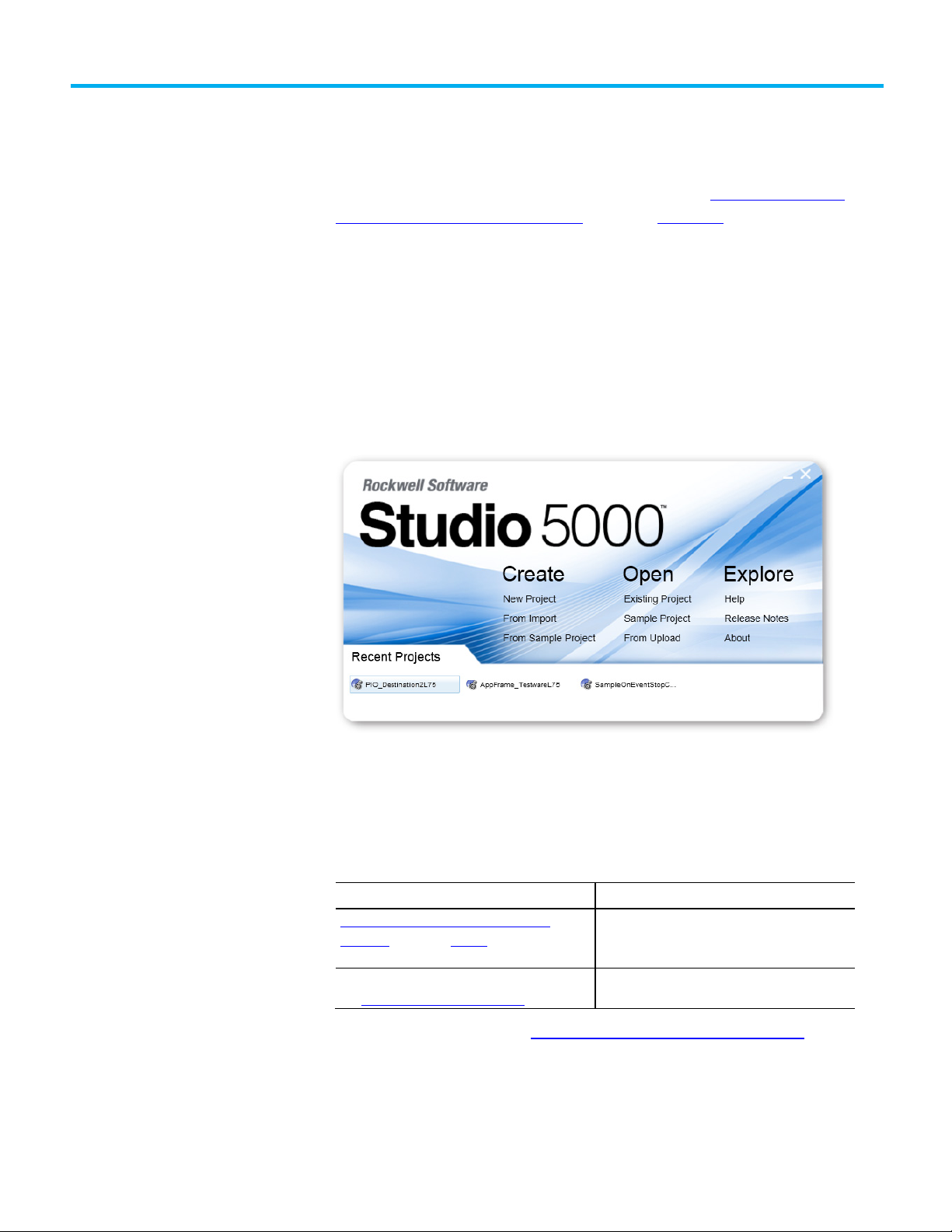
This manual shows how to create and configure program parameters. This manual is one of a
set of related manuals that show common procedures for programming and operating Logix
5000 controllers.
For a complete list of common procedures manuals, refer to the
Logix 5000 Controllers
Common Procedures Programming Manual, publication 1756-PM001.
The term Logix 5000 controller refers to any controller based on the Logix 5000 operating
system.
The Studio 5000 Automation Engineering & Design Environment® combines engineering and
design elements into a common environment. The first element is the Studio 5000 Logix
Designer® application. The Logix Designer application is the rebranding of RSLogix 5000®
software and will continue to be the product to program Logix 5000™ controllers for discrete,
process, batch, motion, safety, and drive-based solutions.
Rockwell Automation Publication 1756-PM021D-EN-P - September 2020 7
The Studio 5000® environment is the foundation for the future of Rockwell Automation®
engineering design tools and capabilities. The Studio 5000 environment is the one place for
design engineers to develop all elements of their control system.
These documents contain additional information concerning related Rockwell Automation
products.
Industrial Automation Wiring and Grounding
Guidelines, publication 1770-4.1
at http://ab.rockwellautomation.com
Provides general guidelines for installing a Rockwell
Automation industrial system.
and other certification details.
View or download publications at http://www.rockwellautomation.com/literature. To order
paper copies of technical documentation, contact the local Rockwell Automation distributor
or sales representative.
Page 8
Preface
Term
Definition
structure, this behavior may be necessary.
change the value during execution of a program.
not change from external code or HMI interaction.
Important terminology
This table defines the terms that are important to understanding the concepts described in
this manual.
Argument An argument is assigned to a parameter and contains
the specification of the data used by an instruction in a
user program. An argument can contain the following:
• A simple tag (for example, L101)
• A literal value (for example, 5)
• A tag structure reference (for example,
Recipe.Temperature)
• A direct array reference (for example, Buffer[1])
• An indirect array reference (for example,
Buffer[Index+1])
•
A combination (for example, Buffer[Index+1].Delay)
InOut parameter An InOut parameter is a special usage program
parameter that represents a reference to data that can
be used both as input and output during the execution
of a program. Because InOut parameters pass by
reference rather than by value, they are merely a pointer
to the original data and closely resemble the behavior of
an alias tag. With that in mind, it is possible that the
InOut parameter values could change during the
execution of a program. Depending on your task
Input parameter An Input parameter is a parameter that defines the data
that is passed by value into an executing program. Since
Input parameters are passed by value, their values
cannot change from external sources during the
execution of the program. An Input parameter supports
a maximum of one sourcing connection.
Output parameter
An Output parameter is a parameter that
defines the data that is produced as a direct
result of executing a program. Since Output
parameters are always passed by value, their
values only change at the end of the scan of a
program when the copy of the parameters has
executed.
Tip: If using direct access another program
can be a source for an Output parameter.
Passed by reference When an argument is passed to a parameter by
reference, the logic directly reads or writes the value
that the tag uses in controller memory. External code or
HMI interaction that changes the argument’s value can
Passed by value When an argument is passed to a parameter by value,
the value is copied in or out of the parameter during
execution of a program. The value of the argument does
8 Rockwell Automation Publication 1756-PM021D-EN-P - September 2020
Page 9

Legal notices
Public parameter A Public parameter is an encapsulated version of a
controller scope tag, and typically it is used for large
data structures that need to be shared among programs.
Preface
Rockwell Automation publishes legal notices, such as privacy policies, license agreements,
trademark disclosures, and other terms and conditions on the Legal Notices
page of the
Rockwell Automation website.
End User License Agreement (EULA)
You can view the Rockwell Automation End User License Agreement (EULA) by opening the
license.rtf file located in your product's install folder on your hard drive.
The default location of this file is:
C:\Program Files (x86)\Common Files\Rockwell\license.rtf.
Open Source Software Licenses
The software included in this product contains copyrighted software that is licensed under
one or more open source licenses.
You can view a full list of all open source software used in this product and their
corresponding licenses by opening the oss_license.txt file located your product's
OPENSOURCE folder on your hard drive. This file is divided into these sections:
• Components
Includes the name of the open source component, its version number,
and the type of license.
• Copyright Text
Includes the name of the open source component, its version number,
and the copyright declaration.
• Licenses
Includes the name of the license, the list of open source components
citing the license, and the terms of the license.
The default location of this file is:
C:\Program Files (x86)\Common Files\Rockwell\Help\<product
name>\Release Notes\OPENSOURCE\oss_licenses.txt.
Rockwell Automation Publication 1756-PM021D-EN-P - September 2020 9
You may obtain Corresponding Source code for open source packages included in this
product from their respective project web site(s). Alternatively, you may obtain complete
Corresponding Source code by contacting Rockwell Automation via the Contact form on the
Rockwell Automation website:
http://www.rockwellautomation.com/global/about-
us/contact/contact.page. Please include "Open Source" as part of the request text.
Page 10

Preface
10 Rockwell Automation Publication 1756-PM021D-EN-P - September 2020
Page 11

Introduction
Program parameters
Program parameter
Chapter 1
Connecting program parameters
This chapter provides an overview of program parameters and then further defines each
type of program parameter. Explanations are provided on when to use each type of program
parameter and the general rules to follow, and example procedures are provided for
connecting each type of program parameter.
A program parameter is an argument that is exposed for external access by a program.
Unlike local tags, all program parameters are publicly accessible outside of the program.
Additionally, HMI external access can be specified for each parameter. Data sharing between
programs can be achieved either through pre-defined connections between parameters or
directly accessed through a special notation.
There are four types of program parameters.
• Input
• Output
• InOut
• Public
Among other benefits, program parameters allow you to clearly define the inputs to the
routines in a program, and the outputs from those routines. Input and Output parameters also
automatically buffer data, so that you do not need to create separate tags to buffer IO data
(although if desired, you can still buffer data using the Synchronous Copy File [CPS]
instruction).
connection methods
Rockwell Automation Publication 1756-PM021D-EN-P - September 2020 11
You can use any of the following methods to connect program parameters in the Logix
Designer application.
• Connections column on the Program Parameters and Local Tags
dialog box
Page 12

Chapter 1 Connecting program parameters
Tip: To show the Connections column click View > Toggle Columns > Connections.
• Ellipses button (...) in the Connections cell on the Program
Parameters and Local Tags dialog box
12 Rockwell Automation Publication 1756-PM021D-EN-P - September 2020
Page 13

Chapter 1 Connecting program parameters
• Properties pane on the Program Parameters and Local Tags dialog
box
• Parameters tab on the Program Properties dialog box
Rockwell Automation Publication 1756-PM021D-EN-P - September 2020 13
Page 14
Chapter 1 Connecting program parameters
Program parameter
User-defined type sub-
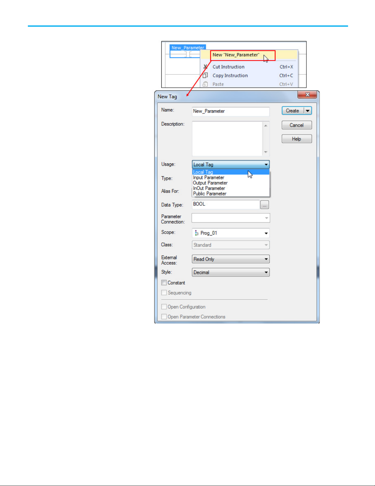
• New Parameter or Tag dialog box
connection syntax
element connection
considerations
14 Rockwell Automation Publication 1756-PM021D-EN-P - September 2020
The syntax {x:y} is used to connect program parameters where:
x = the number of full connections, meaning connections at the word or user-defined
type level
y = the number of partial connections, meaning connections at the bit or member
level
User-defined types (UDTs) used as parameters can contain member-specific connections. To
ensure proper data flow, the base Usage can only be specified at the base of the UDT, and
not at the member level, as the following example shows.
Page 15

methods shown in Program parameter connection methods on page 11.
Input parameters
Input parameter connection
types and uses
General rules for using
Connect an Input parameter
An Input parameter is a parameter that defines the data that is passed by value into an
executing program. Since Input parameters are passed by value, their values cannot change
from external sources during the execution of the program. An Input parameter supports a
maximum of one sourcing connection.
Input parameters can be connected to Output parameters, Public parameters, InOut
parameters, and controller scope tags. This makes Input parameters a great option for
connecting input card data to a code module or object. It also is a good option for code
module or object commands that are point-to-point.
The following are general rules when using Input parameters.
Chapter 1 Connecting program parameters
Input parameters
to a controller scope tag
• Input parameters (including members) can only support one sourcing
connection. This means that only one source can be delivering the
value to the input parameter.
• Input parameter values are refreshed before each scan of a program.
The values do not change during the logic execution, so you do not
need to write code to buffer inputs.
• A program can write to its own Input parameters.
• Data values for Output parameters that are connected to controller
scope tags or Public parameters are copied after the scan of a program.
In a project with multiple tasks, the data copy for a parameter that is of
type BOOL, SINT, INT, DINT, LINT, or REAL will not be interrupted.
The data copy from an Output parameter to a controller scope tag or
Public parameter or any other predefined or user-defined data type
may be interrupted by a task switch.
For more information on the Input parameter connections that can be made, see
parameter connection rules on page 26.
A parameter can be connected to another parameter or controller scope tag. As an example,
connecting an Input parameter to an Output parameter ensures that data is copied to the
Input parameter from the Output parameter on every scan. The following procedure explains
how to connect an Input parameter to a controller scope tag.
Program
Rockwell Automation Publication 1756-PM021D-EN-P - September 2020 15
Tip: This procedure demonstrates the use of the Properties pane on the Program Parameters
and Local Tags dialog box. You can alternatively connect parameters using any of the other
Page 16

Chapter 1 Connecting program parameters
To connect an Input parameter to a controller scope tag
1. In the Controller Organizer, expand the folder for the program for
which you are connecting an Input parameter, and doubleclick Parameters and Local Tags.
2. On the Program Parameters and Local Tags dialog box, choose the
Input parameter that you want to connect.
3. On the right, in the Properties pane, expand Parameter Connections.
4. Click New Connection.
16 Rockwell Automation Publication 1756-PM021D-EN-P - September 2020
Page 17

Output parameters
Chapter 1 Connecting program parameters
5. Click the Browse (...) button.
6. In the Tag box, choose the drop-down arrow.
7. In the Tag Browser, locate and expand the desired controller scope tag.
8. Click to the right of the desired tag, and click the drop-down arrow.
9. Click the bit that you want to associate with this Input parameter.
10. In the Tag box, verify that the resulting information is correct, and
click OK. Notice that the first number in the brackets next
to Parameter Connections has incremented by one, indicating that the
number of connections to the parent tag have increased by one.
An Output parameter is a parameter that defines the data that is produced as a direct result
of executing a program. Since Output parameters are always passed by value, their values
only change at the end of the scan of a program when the copy of the parameters has
executed.
Rockwell Automation Publication 1756-PM021D-EN-P - September 2020 17
Tip: If using direct access another program can be a source for an Output parameter.
Page 18

Chapter 1 Connecting program parameters
connected to the InOut parameter is used.
Program parameter connection methods on page 11.
Output parameter
General rules for using
Connect an Output
Output parameters can be connected to one or more Input parameters, Public parameters,
InOut parameters (constants), and controller scope tags, which makes Output parameters a
connection types and uses
great option for connecting a code module or object to an output card. It also is a good
option for configuring a code module or object to invoke operations (such as commands and
settings) in other code modules or objects. Additionally, multiple connections can be
configured for an Output parameter (known as fanning), which allows one code module or
object to send multiple commands to multiple modules or objects using one Output
parameter.
The following are general rules when using Output parameters.
Output parameters
parameter to a
controller scope tag
• Output parameters, including members, can support multiple
connections. For example, assume you have a BOOL Input parameter
in Program_A named Input1a, and a BOOL Input parameter in
Program_B named Input1b. You are allowed to connect a single Output
parameter in Program_C to both Input1a and Input1b. This is known
as fanout.
• Output parameter values are refreshed after each scan of a program.
They maintain the value from the previous scan until the program
execution is complete.
• Output parameters connected to Public parameters or controller scope
tags are copied (pushed) at the end of the program execution.
• An Output parameter can only be connected to an InOut parameter if
the InOut parameter is configured as a constant.
Tip: InOut parameters are passed by reference, which means they point to the base tag.
That is, when an InOut parameter is used in logic, the current value of the parameter
For more information on the Output parameter connections that can be made, see Program
parameter connection rules on page 26.
The following procedure explains how to connect an Output parameter to a controller scope
tag.
Tip: This procedure demonstrates the use of the Parameters tab on the Program Properties
dialog box. You can alternatively connect parameters using any of the other methods shown in
18 Rockwell Automation Publication 1756-PM021D-EN-P - September 2020
Page 19

Tip: This procedure demonstrates the use of the Properties pane on the Program Parameters
Connect an Output
Chapter 1 Connecting program parameters
To connect an Output parameter to a controller scope tag
1. In the Controller Organizer, double-click the folder for the program
for which you are creating an Output parameter connection.
2. On the Program Properties dialog box, click the Parameters tab.
3. In the Name box, click the name of the Output parameter for which
you want to add a connection.
parameter to
another program
4. In the Connections area, click New Connection.
5. In the New Connection box, type the tag to which you want to connect
this Output parameter, and click Apply.
6. Click OK to close the Program Properties dialog box.
The following procedure explains how to connect an Output parameter to another program.
and Local Tags dialog box. You can alternatively connect parameters using any of the other
methods shown in
Program parameter connection methods on page 11.
Rockwell Automation Publication 1756-PM021D-EN-P - September 2020 19
Page 20

Chapter 1 Connecting program parameters
To connect an Output parameter to another program
1. In the Controller Organizer, expand the folder for the program for
which you are creating an Output parameter connection, and doubleclick Parameters and Local Tags.
2. On the Program Parameters and Local Tags dialog box, choose the
Output parameter that you want to connect.
3. On the right, in the Properties pane, expand Parameter Connections.
20 Rockwell Automation Publication 1756-PM021D-EN-P - September 2020
Page 21

InOut parameters
InOut parameter connection
Chapter 1 Connecting program parameters
4. Click New Connection.
5. Click the Browse (...) button.
6. In the Tag box, choose the drop-down arrow.
7. (optional) On the Tag Browser, clear one or more of the check boxes to
limit the number of available parameters that appear in the list.
types and uses
Rockwell Automation Publication 1756-PM021D-EN-P - September 2020 21
8. In the Show parameters from other program list, choose the program
to which you want to connect this Output parameter.
9. In the list of available parameters, double-click the desired parameter.
10. Click OK.
An InOut parameter is a special usage program parameter that represents a reference to
data that can be used both as input and output during the execution of a program. Because
InOut parameters pass by reference rather than by value, they are merely a pointer to the
original data and closely resemble the behavior of an alias tag. With that in mind, it is
possible that the InOut parameter values could change during the execution of a program.
Depending on your task structure, this behavior may be necessary.
InOut parameters can be connected to Input parameters, Public parameters, Output
parameters (if InOut is constant), and controller scope tags.
An example of how InOut parameters are advantageous is an application that contains
multiple tasks with different priority assignments. In this scenario, a lower priority task is
interrupted by a higher priority task. If the higher priority task is referencing data in the lower
priority task, the InOut parameter allows the higher priority task to point directly to a tag’s
Page 22

Chapter 1 Connecting program parameters
methods shown in Program parameter connection methods on page 11.
General rules for using
Connect an InOut parameter
value in the lower priority task. This ensures that the higher priority task is using the most
up-to-date value of a tag.
Another useful scenario for InOut parameters is for instructions whose tags can only be
placed at the controller scope, such as the Message (MSG) instruction. InOut parameters can
connect directly to the MSG instruction tags in the controller scope.
Finally, InOut parameters are useful for programs that have a large data structure, and you do
not want to pass the whole structure by value.
The following are general rules when using InOut parameters.
InOut parameters
to a controller scope tag
• InOut parameters can only support one connection. You cannot
configure connections to any member of an InOut parameter.
• An InOut parameter can only be connected to an Output parameter if
the InOut parameter is configured as a constant.
• InOut parameters are passed by reference, which means they point to
the base tag. In other words, when an InOut parameter is used in logic,
the current value of the parameter connected to the InOut parameter
is used.
• Connections to InOut parameters cannot be changed online, unless
using the Partial Import Online (PIO) functionality.
For more information on the InOut parameter connections that can be made, see
Program
parameter connection rules on page 26.
The following procedure explains how to connect an InOut parameter to a controller scope
tag.
Tip: This procedure demonstrates the use of the Properties pane on the Program Parameters
and Local Tags dialog box. You can alternatively connect parameters using any of the other
22 Rockwell Automation Publication 1756-PM021D-EN-P - September 2020
To connect an InOut parameter to a controller scope tag
1. In the Controller Organizer, expand the folder for the program for
which you are creating an InOut parameter connection, and doubleclick Parameters and Local Tags.
Page 23

Public parameters
Public parameter
Chapter 1 Connecting program parameters
2. On the Program Parameters and Local Tags dialog box, choose the
InOut parameter that you want to connect.
3. On the right, in the Properties pane, expand Parameter Connections,
and click New Connection.
4. Click the Browse (...) button.
5. In the Tag box, choose the drop-down arrow.
6. (optional) On the Tag Browser, clear all but the Show controller tags
check box to limit the number of available parameters that appear in
the list.
7. In the list of available parameters, double-click the desired parameter.
8. Click OK.
A Public parameter is an encapsulated version of a controller scope tag, and typically it is
used for large data structures that need to be shared among programs.
connection types and uses
Rockwell Automation Publication 1756-PM021D-EN-P - September 2020 23
Public parameters can be connected to Input parameters, Output parameters, and InOut
parameters. Public parameters function like controller scope tags, but are at the program
level. The key benefit to using Public parameters over controller scope tags is better
encapsulation. It is an excellent option for code modules or objects that contain data that
must be globally available to other code modules.
Page 24

Chapter 1 Connecting program parameters
General rules for using
Connect a Public parameter
Public parameters are updated as the source updates, so higher priority tasks that interrupt a
program during execution have access to any updated values in the lower priority task.
Additionally, fan-in is supported with Public parameters, which is useful in situations where a
code module or object could receive a command from many modules or objects. Input
parameters can be used, but an individual Input parameter is required for each connection. In
other words, if a code module or object had a command that could be invoked by 10 different
code modules or objects then 10 input parameters are required. However, if the command is
configured as a Public parameter, then all 10 code modules or objects could have an Output
parameter connected to a single Public parameter.
The following are general rules when using Public parameters.
Public parameters
to another program
• Public parameters can support multiple connections. You can
configure connections to the base Public parameter or any member of
a Public parameter, including User-defined structures.
• Public parameters are updated when the source is updated. In other
words, when a Public parameter value updates, it is immediately
available to any higher priority tasks that are connected to that
parameter.
• While Public parameters cannot be connected to controller scope tags,
they can be aliased to controller scope tags. If this functionality is
desired, it is important to remember that the alias updates
asynchronous to program execution. The Public parameter contains
the real-time value of the controller scope tag.
For more information on the Public parameter connections that can be made, see
Program
parameter connection rules on page 26.
The following procedure explains how to change an existing tag to a Public parameter, and
then connect a Public parameter to another program.
Tip: This procedure demonstrates the use of the Properties pane on the Program Parameters
and Local Tags dialog box. You can alternatively connect parameters using any of the other
methods shown in Program parameter connection methods on page 11
.
24 Rockwell Automation Publication 1756-PM021D-EN-P - September 2020
Page 25

Chapter 1 Connecting program parameters
To connect a Public parameter to another program
1. In the Controller Organizer, expand the folder for the program for
which you are creating a Public parameter connection, and doubleclick Parameters and Local Tags.
2. On the Program Parameters and Local Tags dialog box, click the Edit
Tags tab.
3. Locate the tag you want to change to a Public parameter, and in
the Usage box, choose Public Parameter.
4. On the right, in the Properties pane, expand Parameter Connections,
and click New Connection.
5. Click the Browse (...) button.
6. In the Tag box, choose the drop-down arrow.
Rockwell Automation Publication 1756-PM021D-EN-P - September 2020 25
Page 26

Chapter 1 Connecting program parameters
General rules for
Program parameter
7. On the Tag Browser, in the Show parameters from other program list,
choose the program to which you want to connect this Public
parameter.
8. In the list of available parameters, double-click the desired parameter.
9. Click OK.
Safety program parameters
connecting parameters for
safety programs
Special considerations apply when using program parameters within safety programs.
The following are general rules when connecting parameters for safety programs.
• A safety parameter cannot connect to a standard parameter or
controller scoped tag of standard class; the controller scope must be of
class safety.
• A safety parameter can source a standard parameter, as shown in the
following image.
• Safety Output parameters cannot connect to a standard class InOut
parameter.
• Safety local tags can alias safety class controller scope tags.
• Safety Public parameters can alias safety class controller scope tags.
connection rules
26 Rockwell Automation Publication 1756-PM021D-EN-P - September 2020
The following tables summarize the program parameter connection rules.
Page 27

Tip: The connection rules for programs also apply to Equipment Phases.
(Standard)
Program_B
Input
Output
InOut
Public
Controller Scope Tag
Input
—
Yes — Yes
Yes
Output
InOut
—
Yes*
—
Yes
Yes
Public
Controller Scope Tag
(Standard Class)
(Safety)
Program_B
Input
Output
InOut
Public
Controller Scope Tag
Input
—
Yes — Yes
Yes
Output
InOut
—
Yes* — Yes
Yes
Public
Yes
Yes
Yes — Alias
Controller Scope Tag
Standard program to
Safety program to safety
standard program
connection rules
Chapter 1 Connecting program parameters
The following table summarizes the rules for using program parameters to connect two
standard programs.
(Standard)
program connection rules
Program_A
(Standard Class)
Yes — Yes* Yes Yes
Yes Yes Yes — Alias
Yes Yes Yes Alias Alias
• * An InOut parameter can only be connected to an Output parameter if
the InOut parameter is configured as a constant.
• An Input parameter from Program_A can connect to an Output
parameter of Program_A (wrap around).
• Parameters of the same type cannot be connected together.
• Public tags can only bind to controller scope tags using an alias.
The following table summarizes the rules for using program parameters to connect two
safety programs.
Tip: The connection rules for programs also apply to Equipment Phases.
(Safety)
(Safety Class)
Rockwell Automation Publication 1756-PM021D-EN-P - September 2020 27
Program_A
(Safety Class)
Yes — Yes* Yes Yes
Yes Yes Yes Alias Alias
• * An InOut parameter can only be connected to an Output parameter if
the InOut parameter is configured as a constant.
• An Input parameter from Program_A can connect to an Output
parameter of Program_A (wrap around).
Page 28

Chapter 1 Connecting program parameters
Tip: The connection rules for programs also apply to Equipment Phases.
(Safety)
Program_B
Input
Output
InOut
Public
Controller Scope Tag
Input
—
Yes — Yes
Yes
Output
InOut
Public
Controller Scope Tag
(Safety Class)
Safety program to standard
The following table summarizes the rules for using program parameters to connect a safety
program connection rules
program to a standard program.
• Safety mapping must be used to connect standard class tags to safety
class tags/parameters.
• Standard class tags cannot alias safety class tags.
Program_A
(Standard)
— — — — —
— — — — —
— — — — —
Yes Yes Yes Alias Alias
(Safety Class)
• An Input parameter from Program_A can connect to an Output
parameter of Program_A (wrap around).
• Safety mapping must be used to connect standard class tags to safety
class tags/parameters.
• Standard class tags cannot alias safety class tags.
28 Rockwell Automation Publication 1756-PM021D-EN-P - September 2020
Page 29

Introduction
Direct access
Behavior of direct
Access program
Chapter 2
Directly accessing program parameters
This chapter provides an overview of direct access and an example procedure for directly
accessing program parameters when working within code editors.
Direct access lets you reference the program parameters from another program in logic
without configuring parameters in the local program. The syntax used for direct access is
\ProgramName.ParameterName. For example, assume Program_A has an output parameter
called Tank_Level. Without creating a corresponding input parameter to connect to
Program_A, Program_B can reference the Tank_Level parameter in logic using the syntax
\A.Tank_Level.
Program local tags cannot be accessed using direct access.
access in logic
parameters when editing
ladder logic
Input, Output, and Public parameters can all be directly accessed in logic.
• When direct access is implemented in Output parameters, values are
updated when the program that contains the Output parameter
completes execution.
• When direct access is implemented in Input and Public parameters,
the values of the referenced parameters are updated in real time. This
means that higher priority tasks are using parameter values that are up
to date, thus minimizing the risk of performing actions on stale data.
• Direct access to an Input parameter counts toward fan-in. You cannot
have both a connection and a direct access sourcing an Input
parameter. You can however still use direct access to read the value.
• Using direct access of Input parameters is a good way to circumvent
the one connection limit of Input parameters. If you create an Input
parameter but do not configure any connections for that Input
parameter, you can directly reference it from multiple programs.
The following procedure explains how to access program parameters when editing ladder
logic.
Tip: While this example is specific to ladder logic, the notation is the same for all programming
languages.
Rockwell Automation Publication 1756-PM021D-EN-P - September 2020 29
Page 30

Chapter 2 Directly accessing program parameters
To access program parameters when editing ladder logic
1. In the Controller Organizer, expand the folder for the program that
2. In the Ladder Editor Routine, locate the instruction for which you
3. Double-click the existing tag name (it appears as ? if currently
contains the ladder logic routine that contains instructions for which
you are configuring direct access, and double-click the routine.
want to add a reference to a program parameter that is in another
program.
unassigned), and choose the drop-down arrow.
4. (optional) On the Tag Browser, clear or select the check boxes to focus
the list of available parameters that appear to what you need.
5. In the Show parameters from other program list, choose the program
to which you want to connect this instruction.
6. In the list of available parameters, double-click the desired parameter.
30 Rockwell Automation Publication 1756-PM021D-EN-P - September 2020
Page 31

Index
A
argument 8
C
connect
InOut parameter 22
Input parameter 15
Output parameter 18, 19
Public parameter 24
connection methods 11
Index
passed by value 8
program parameter
connect 11
connection methods 11
connection of UDT sub-elements 14
connection syntax 14
Public parameter
connect to another program 24
connection types and uses 23
general connection rules 24
overview 23
S
safety program parameters
general connection rules 26
overview 26
U
D
direct access
behavior 29
overview 29
use 29
I
InOut parameter
connect to a controller scope tag 22
connection types and uses 21
general connection rules 22
overview 21
Input parameter
connect to a controller scope tag 15
connection types and uses 15
general connection rules 15
overview 15
O
Output parameter
connect to a controller scope tag 18
connect to another program 19
connection types and uses 18
general connection rules 18
overview 17
UDT sub-elements 14
P
passed by reference 8
Rockwell Automation Publication 1756-PM021D-EN-P - September 2020 31
Page 32

Technical Support Center
Find help with how-to videos, FAQs, chat, user forums, and product notification
rok.auto/support
Knowledgebase
Access Knowledgebase articles.
rok.auto/knowledgebase
Local Technical Support Phone Numbers
Literature Library
Product Compatibility and Download Center
Rockwell Automation support
Use these resources to access support information.
updates.
Locate the telephone number for your country. rok.auto/phonesupport
Find installation instructions, manuals, brochures, and technical data publications. rok.auto/literature
(PCDC)
Get help determining how products interact, check features and capabilities, and
find associated firmware.
rok.auto/pcdc
Documentation feedback
Your comments help us serve your documentation needs better. If you have any suggestions on how to improve our content, complete the form
at rok.auto/docfeedback
.
Waste Electrical and Electronic Equipment (WEEE)
At the end of life, this equipment should be collected separately from any unsorted municipal waste.
Rockwell Automation maintains current product environmental information on its website at rok.auto/pec.
Allen-Bradley, expanding human possibility, Logix, Rockwell Automation, and Rockwell Software are trademarks of Rockwell Automation, Inc.
EtherNet/IP is a trademark of ODVA, Inc.
Trademarks not belonging to Rockwell Automation are property of their respective companies.
Rockwell Otomayson Ticaret A.Ş. Kar Plaza İş Merkezi E Blok Kat:6 34752, İçerenkÖy, İstanbul, Tel: +90 (216) 5698400 EEE YÖnetmeliğine Uy gundur
Rockwell Automation Publication 1756-PM021D-EN-P - September 2020
Supersedes Publication 1756-PM021C-EN-P - February 2018 Copyright © 2020 Rockwell A utomation Technologies, Inc. All Rights Rese rved. Printed in the U.S.A.
 Loading...