

Page 1

Installation Instructions
H-Series Brushless Servo Motor
(Catalog Number H-2005, H-3007, H-3016, H-4030, H-4050, H-4075, H-6100, H-6200,
H-6300, H-8350, and H-8500)
These Installation Instructions describe how to install the H-Series
motors. Use this document if you are responsible for designing,
installing, or troubleshooting the Allen-Bradley
products. Read all instructions before installing this motor.
For: See Page
Receiving and Maintenance Information 2
Motor Catalog Number Identification 2
Before You Install the Motor 3
Using Shaft Seals 3
Using Couplings and Pulleys 4
Preventing Electrical Noise 5
®
H-Series motor
Building and Installing Cables 6
Installing Your Motor 7
Guidelines for Installation 8
Mounting Dimensions 9
Connector Data 12
Feedback Connectors 12
Power Connector and Brake Connector 13
Motor Load Force Ratings 14
Motor Radial Load Force Ratings 15
Cables and Connector Kits 16
Shaft Seal Kits 17
Publication 1398-IN517A-EN-P — August 2001
Page 2
2 H-Series Motor Installation Instructions
Receiving and Maintenance Information
The customer is responsible for inspecting the equipment before
accepting the shipment from the freight company. Check the item(s) you
receive against your purchase order.
Maintain your motor within the following environmental conditions:
• in a clean, dry location
• within the operating temperature range, 0° to 40° C (32° to 104° F)
• within the storage temperature range, -30° to 70° C (-25° to 158° F)
• within the relative humidity range, 5% to 95% non-condensing
• in a non-corrosive atmosphere
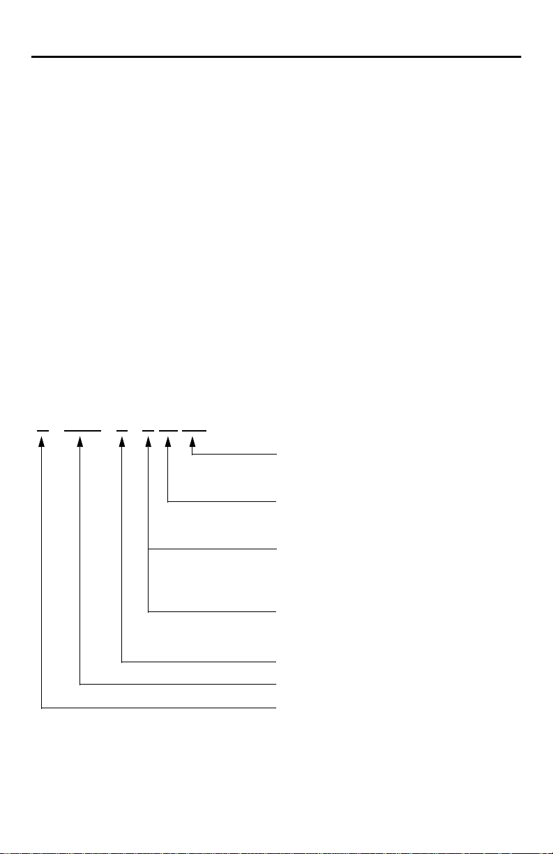
Motor Catalog Number Identification
H - 4030 - P - H 00 AA
FACTORY DESIGNATED OPTIONS
AA Standard Flange
AN NEMA
OPTIONS
00 Standard
04 24V DC Brake
OPTICAL ENCODER LINE COUNT
F 1000
H 2000 (Standard)
K 5000 1
L 500
M 3000
HIGH RESOLUTION ENCODER
M2 Multi-turn
S2 Single-turn
MOTOR WINDING Ke DESIGNATOR
FRAME SIZE
SERIES DESIGNATOR
1
The 5000 line count encoder limits the motor’s top speed to 3600 RPM due to frequency output limit of the encoder.
Check drive system configuration data for additional restrictions imposed by drive input.
Publication 1398-IN517A-EN-P — August 2001
H
Low Inertia
Page 3
H-Series Motor Installation Instructions 3
ATTENTION
!
Before You Install the Motor
Before installing or storing the motor:
1. Remove the motor carefully from its shipping container.
2. Visually inspect the motor for any damage.
3. Examine the motor frame, front output shaft, and mounting pilot for
any defects.
4. Notify the carrier of any shipping damage immediately.
Do not open or attempt to open the motor.
Only a qualified Allen-Bradley employee can
service this type of motor.
Failure to observe these safety procedures could
result in personal injury or equipment damage.
Using Shaft Seals
An additional seal is required on the motor shaft near the motor front
bearing, if the shaft is exposed to fluids or significant amounts of fine
dust. This includes lubricating oil from a gearbox. The motor ingress
protection (IP) rating depends on the usage of shaft seals and
environmentally sealed connectors/cables. The additional seal is not
recommended in applications where the motor shaft area is free of liquids
or fine dust. Refer to Shaft Seal Kits on page 17 to find the catalog number
of the seal kit for your H-Series motor.
Publication 1398-IN517A-EN-P — August 2001
Page 4
4 H-Series Motor Installation Instructions
ATTENTION
!
Using Couplings and Pulleys
Mechanical connections to the motor shaft, such as couplings and pulleys,
require a torsionally rigid coupling or a reinforced timing belt. The high
dynamic performance of servo motors can cause couplings, pulleys or
belts to loosen or slip over time. A loose or slipping connection will cause
system instability and may damage the motor shaft. All connections
between the system and the servo motor shaft must be rigid to achieve
acceptable response from the system. Periodically inspect connections to
verify their rigidity.
When mounting couplings or pulleys to the motor shaft, ensure that the
connections are properly aligned and that axial and radial loads are within
the specifications of the motor. Refer to Motor Load Force Ratings on
page 14 for guidelines on how to achieve 20,000 hours of motor bearing
life.
Damage may occur to the motor bearings and the
feedback device if sharp impact to the shaft is
applied during installation of couplings and pulleys.
Damage to the feedback device may result by
applying leverage from the motor mounting face to
remove devices mounted on the motor shaft.
Do not strike the shaft, couplings, or pulleys with
tools during installation or removal. Use a wheel
puller applying pressure from the user end of the
shaft to remove any friction fit or stuck device from
the motor shaft.
Failure to observe these safety procedures result in
damage to the motor and its components.
Publication 1398-IN517A-EN-P — August 2001
Page 5

H-Series Motor Installation Instructions 5
Preventing Electrical Noise
ElectroMagnetic Interference (EMI), commonly called noise, may
adversely impact motor performance by inducing stray signals. Effective
techniques to counter EMI include filtering the AC power, shielding and
separating signal carrying lines, and practicing good grounding
techniques.
Effective AC power filtering can be achieved by using isolated AC power
transformers or properly installed AC line filters.
To help avoid EMI:
1. Physically separate signal lines from motor cabling and power wiring.
Do not route signal wires with motor and power wires, or over the vent
openings of servo drives.
2. Ground all equipment using a single-point parallel ground system that
employs ground bus bars or large straps. If necessary, use additional
electrical noise reduction techniques to reduce EMI in noisy
environments.
Publication 1398-IN517A-EN-P — August 2001
Page 6
6 H-Series Motor Installation Instructions
ATTENTION
!
ATTENTION
!
Building and Installing Cables
Knowledgeable cable routing and careful cable construction improves
system ElectroMagnetic Compatibility (EMC).
To build and install cables, perform the following steps:
1. Keep wire lengths as short as possible.
2. Route signal cables (encoder, serial, analog) away from motor and
power wiring.
3. Separate cables by a minimum of 0.3 m (1 ft) for every 9 m (30 ft) of
parallel run.
4. Ground both ends of the encoder cable shield, and twist the signal wire
pairs to prevent electromagnetic interference (EMI) from other
equipment.
High voltage can be present on the shield of a
power cable if the shield is not grounded.
Ensure there is a connection to ground for any
power cable shield.
Failure to observe these safety procedures could
result in personal injury or equipment damage.
H-Series motors with high resolution encoders
require the use of Allen-Bradley power and
feedback cables.
H-Series connector kits do not provide the
necessary connector grounding for use with high
resolution encoders.
Failure to observe these safety procedures could
result in personal injury or equipment damage.
Publication 1398-IN517A-EN-P — August 2001
Page 7

H-Series Motor Installation Instructions 7
ATTENTION
!
ATTENTION
!
Installing Your Motor
The installation must comply with all local regulations and use of
equipment and installation practices that promote electromagnetic
compatibility (EMC) and safety. Preferred fasteners are stainless steel.
Unmounted motors, disconnected mechanical
couplings, and/or disconnected cables are
dangerous if power is applied.
Disassembled equipment should be appropriately
identified (tagged-out) and access to electrical
power restricted (locked-out).
Before applying power to the motor, remove the
shaft key and other mechanical couplings which
could be thrown from the shaft.
Failure to observe these safety procedures could
result in personal injury or equipment damage.
An H-Series Personality Module must be installed
on servo drives requiring a Personality Module.
Rapid shaft rotation up to one revolution may
occur when the drive is enabled, if an H-Series
Personality Module is not installed.
Failure to observe these safety procedures could
result in personal injury or equipment damage.
Publication 1398-IN517A-EN-P — August 2001
Page 8

8 H-Series Motor Installation Instructions
ATTENTION
!
Guidelines for Installation
Observe the following for installing the motor:
1. Allow sufficient clearance around the motor to keep it within its
specified operating temperature range. Refer to Receiving and
Maintenance Information on page 2 for operating range. Do not
enclose the motor unless forced air is blown across the motor for
cooling. A fan blowing air across the motor will improve its
performance. Keep other heat-producing devices away from the motor.
2. Refer to Mounting Dimensions on page 9 to determine the mounting
dimensions of your motor.
3. Place the motor with connectors pointing downward.
4. Properly mount and align the motor.
5. Attach all power and encoder cables after the motor is mounted, and
use a drip loop in the cable to keep liquids flowing away from the
connectors.
Outer surfaces of motor can reach high
temperatures, 100° C (212° F) during motor
operation.
Take precautions to prevent accidental contact with
hot surfaces. Consider motor surface temperature
when selecting motor mating connections and
cables.
Failure to observe these safety procedures could
result in personal injury or equipment damage.
Publication 1398-IN517A-EN-P — August 2001
Page 9

H-Series Motor Installation Instructions 9
Mounting Dimensions
The dimension symbols and actual dimensions of the different models in
the H-Series are referenced in tables on pages 9 and 10.
Figure 1
H-2000 Standard Mounting Dimensions
S = Outside Dia. x Inside Dia.
AH
T
BE
EA
D
EB
AD
Power
Connector
P
Feedback
Connector
L
Figure 2
H-3000, -4000, -6000, and -8000 Standard Mounting Dimensions
2 Eyebolts provided
with motor
(H-6000 and H-8000
Series only)
AD
L
AH
BE
T
EA
EB
BF = DIA. HOLES
AJ = DIA. BOLT CIRCLES
63.5 mm SQ
(2.5 in.)
Shaft End
Threaded
M
D
Hole
S = Outside Dia. x Inside Dia.
P
9
Shaft End
Threaded
9
Hole
Power
Connector
Feedback
Connector
Brake
Option
M
BF = DIA. HOLE
AJ = DIA. BOLT CIRCLE
Publication 1398-IN517A-EN-P — August 2001
Page 10

10 H-Series Motor Installation Instructions
Dimension
(Refer to drawing)
AD mm 75 75 75 76 76 76 101 101 101
AH mm 23 30 30 50 50 50 80 80 80 85 85
H-Series Motor
2005 3007 3016 4030 4050 4075 6100 6200 6300 8350 8500
112 112
(in.) (2.95) (2.95) (2.95) (3) (3) (3) (4) (4) (4.41) (4.41)
3
(in.) (0.9)
(1.18)3(1.18)3(1.97)3(1.97)3(1.97)3(3.15)3(3.15)3(3.15)3(3.35)3(3.35)
(4)
3
AJ mm 75 100 100 145 145 145 200 200 200 265 265
(in.) (2.95) (3.94) (3.94) (5.71) (5.71) (5.71) (7.87) (7.87) (7.87) (10.43) (10.43)
BE mm 15.2 10.9 10.9 15.5 15.5 15.5 21.3 21.3 21.3 22.4 22.4
(in.) (0.6) (0.43) (0.43) (0.61) (0.61) (0.61) (0.84) (0.84) (0.84) (0.88) (0.88)
BF mm 5.8 7 7 10 10 10 13.5 13.5 13.5 15 15
(in.) (0.23) (0.28) (0.28) (0.39) (0.39) (0.39) (0.53) (0.53) (0.53) (0.59) (0.59)
D mm 11 14 14 19 19 19 35 35 35 42 42
(in.) (0.43)
2
(0.55)2(0.55)2(0.75)2(0.75)6(0.75)6(1.38)7(1.38)7(1.38)7(1.65)7(1.65)
7
EA mm 18 20 20 40 40 40 60 60 60 60 60
(in.) (0.71) (0.79) (0.79) (1.57) (1.57) (1.57) (2.36) (2.36) (2.36) (2.36) (2.36)
EB mm 12 15 15 20 20 20 38 38 38 45 45
(in.) (0.47) (0.59) (0.59) (0.79) (0.79) (0.79) (1.5) (1.5) (1.5) (1.77) (1.77)
L
(see Note a)
L
(see Note b)
L
(see Note c)
L
(see Note d)
M mm 60 80 80 110 110 110 114.3 114.3 114.3 230 230
mm 197 172 223 213 264 315 277 353 429 375 426
(in.) (7.7) (6.77) (8.77) (8.39) (10.39) (12.4) (10.91) (13.9) (16.89) (14.76) (16.77)
mm
(in.) (8.31) (10.31) (10.47) (12.48) (14.49) (12.99) (15.98) (18.98) (18.82) (20.83)
mm
(in.) (10.71) (13.70) (16.69) (14.53) (16.54)
mm
(in.) (12.80) (15.79) (18.78) (18.58) (20.59)
(in.) (2.36)
211 262 266 317 368 330 406 482 478 529
–
––––––
––––––
1
(3.15)1(3.15)1(4.33)5(4.33)5(4.33)5(4.5)5(4.5)5(4.5)5(9.06)8(9.06)
272 348 424 369 420
325 401 477 472 523
8
P mm 80 89 89 121 121 121 178 178 178 241 241
(in.) (3.15) (3.5) (3.5) (4.76) (4.76) (4.76) (7.01) (7.01) (7.01) (9.49) (9.49)
S mm 4 x 4 5 x 5 5 x 5 6 x 6 6 x 6 6 x 6 10 x 8 10 x 8 10 x 8 12 x 8 12 x 8
(in.) (0.16 x
T mm2.433333444 44
(in.) (0.09)
To le ra nc es :
1
Tolerance is –0.03 mm (–0.0012 in.).
2
Tolerance is –0.01 mm (–0.0004 in.).
3
Tolerance is ±0.5 mm (±0.0196 in.).
4
Tolerance is ±0.2 mm (±0.0079 in.).
5
Tolerance is –0.035 mm (–0.0014 in.).
7
Tolerance is –0.16 mm (–0.0006 in.).
8
Tolerance is –0.46 mm (–0.0181 in.).
(0.2 x
(0.2 x
(0.24 x
(0.24 x
(0.24 x
(0.39 x
(0.39 x
0.16)
0.2)
0.2)
0.24)
0.24)
.24)
0.31)
4
(0.12)4(0.12)4(0.12)4(0.12)4(0.12)4(0.16)4(0.16)4(0.16)4(0.16)4(0.16)
9
H-2000 Thread = M3 x 0.5 mm (0.0197 in.), Thread Depth = 10 mm (0.39 in.).
H-3000 Thread = M3 x 0.5 mm (0.0197 in.), Thread Depth = 10 mm (0.39 in.).
H-4000 Thread = M6 x 1 mm (0.0394 in.), Thread Depth = 15 mm (0.59 in.).
H-6000 and H-8000 Thread = M8 x 1.25 mm (0.0492 in.), Thread Depth = 20 mm (0.79 in.).
0.31)
(0.39 x
0.31)
(0.47 x
0.31)
(0.47 x
0.31)
4
Notes:
a = Optical encoder, without Brake c = High Resolution Encoder without Brake
b = Optical encoder with Brake d = High Resolution with Brake
Publication 1398-IN517A-EN-P — August 2001
Page 11

H-Series Motor Installation Instructions 11
Dimension
(Refer to
drawing)
L
Brake Option
Motor
H-4030
NEMA 56C
AH
EC
T
EA
D
EB
H-4050
NEMA 56C
M
R
H-4075
NEMA 56C
AH mm 52 52 52
(in.) (2.06)
1
(2.06)
1
(2.06)
1
D mm 15.9 15.9 15.9
(in.) (0.625)
4
(0.625)
4
(0.625)
EA mm 36 36 36
(in.) (1.41) full depth (1.41) full depth (1.41) full depth
EB mm 50.8 50.8 50.8
(in.) (2) (2) (2)
EC mm 15.5 15.5 15.5
(in.) (0.61) (0.61) (0.61)
L
(see Note a)
L
(see Note b)
mm 213 264 315
(in.) (8.39) (10.39) (12.4)
mm 266 317 368
(in.) (10.47) (12.48) (14.49)
M mm 114.3 114.3 114.3
(in.) (4.5)
2
(4.5)
2
(4.5)
2
R mm 47 x 20 47 x 20 47 x 20
(in.) (1.85 x 0.788) (1.85 x 0.788) (1.85 x 0.788)
S mm 165 165 165
(in.) (6.5) (6.5) (6.5)
T mm 3 3 3
(in.) (0.12)
3
(0.12)
3
(0.12)
3
U mm 4.8 x 35 4.8 x 35 4.8 x 35
(in.) (0.1875 x 1.375) (0.1875 x 1.375) (0.1875 x 1.375)
To le ra nc es :
1
Tolerance is ±0.508 mm (±0.02 in.)
2
Tolerance is –.0762 mm (–0.003 in.)
3
Tolerance is ±0.254 mm (±0.01 in.)
4
Tolerance is –0.0127 mm (–0.0005 in.)
Notes:
a = Optical encoder without Brake b = Optical encoder with Brake
U
3/8 - 16 through (4) eq. sq.
90º apart on a 149 mm
(5.875 in.) diameter BC
S
4
Publication 1398-IN517A-EN-P — August 2001
Page 12

12 H-Series Motor Installation Instructions
A
B
C
D
E
F
G
H
J
K
L
M
N
P
RS
T
Connector Data
The tables below list the signal descriptions for the feedback, power and
brake connector pins.
Feedback Connectors
Encoder High Resolution
Pin Signal Pin Signal
AA+ ASin+
BA- BSinCB+ CCos+
DB- DCosEI+ EData+
FI- FDataG Encoder Case G Reserved
HABS H
J +5V DC J
K +5V DC K +5V DC
LCOM LCommon
MCOM MReserved
NHall B N
PHall C P
RTS+ RTS+
STS- STST Hall A T Reserved
M
L
K
J
Publication 1398-IN517A-EN-P — August 2001
B
A
C
P
T
N
D
E
RS
F
H
G
Page 13

H-Series Motor Installation Instructions 13
D
A
CB
Power Connector and Brake Connector
Power Connector Brake Connector
Pin Signal Pin Signal
AU ABR+
BV BBR-
CW
D Motor Case
BA
Publication 1398-IN517A-EN-P — August 2001
Page 14

14 H-Series Motor Installation Instructions
Motor Load Force Ratings
Motors are capable of operating with sustained maximum radial or
maximum axial shaft loads. The measurement points for maximum radial
and axial load forces are shown in the figure below.
Figure 3
Load Forces on Shaft
Radial load force applied at the
center of the shaft extension
Axial load force
Publication 1398-IN517A-EN-P — August 2001
Page 15

Motor Radial Load Force Ratings
H-Series Motor Installation Instructions 15
Motor
H-2005 kg 63.5 50.8 39.9 34.9 31.8 29.5 20.4
(lb) (140) (112) (88) (77) (70) (65) (45)
H-3007 kg 68 54.4 43.1 37.6 34 31.8 –
(lb) (150) (120) (95) (83) (75) (70) –
H-3016 kg 76.2 60.8 47.6 41.7 38.1 35.4 –
(lb) (168) (134) (105) (92) (84) (78) –
H-4030-M kg 102.1 91.6 72.6 63.5 57.6 ––
(lb) (225) (202) (160) (140) (127) ––
H-4030-P kg 102.1 91.6 72.6 63.5 57.6 ––
(lb) (225) (202) (160) (140) (127) ––
H-4050 kg 123.8 98.9 78.0 68.0 62.1 ––
(lb) (273) (218) (172) (150) (137) ––
H-4075 kg 129.7 104.3 82.6 71.2 65.3 ––
(lb) (286) (230) (182) (156) (144) ––
H-6100 kg 263.1 208.7 165.6 145.2 –––
(lb) (580) (460) (365) (320) –––
500
RPM
1000
RPM
2000
RPM
3000
RPM
4000
RPM
5000
RPM
6000
RPM
H-6200 kg 283.5 226.8 179.2 156.5 –––
(lb) (625) (500) (395) (345) –––
H-6300 kg 299.4 235.9 188.2 163.3 –––
(lb) (660) (520) (415) (360) –––
H-8350 kg 299.4 238.1 188.2 ––––
(lb) (660) (525) (415) ––––
H-8500 kg 313.0 249.5 197.3 ––––
(lb) (690) (550) (435) ––––
With no radial load, the axial load rating is 100% of the radial load rating
from the table above. With a radial and an axial load, the axial load rating
is 44% of the radial load rating from the table above.
Publication 1398-IN517A-EN-P — August 2001
Page 16

16 H-Series Motor Installation Instructions
ATTENTION
!
Cables and Connector Kits
CE compliant cables are available from Allen-Bradley in standard cable
lengths. Contact your nearest Allen-Bradley sales office or refer to your
drive’s installation manual for a complete listing of available cables.
If you choose to build your own cables, the following non-CE compliant
connector kits are available for H-Series motors with optical encoders
H-Series motors with high resolution encoders
require the use of Allen-Bradley power and
feedback cables.
H-Series connector kits do not provide the
necessary connector grounding for use with high
resolution encoders.
Failure to observe these safety procedures could
result in personal injury or equipment damage.
.
Catalog
Number
2090-HPC-S2000 Straight Power Connector Kit Compatible with 500W, 1 and 2 kW Drives
2090-HPC-R2000 Right-Angle Power Connector Kit Compatible with 500W, 1 and 2 kW Drives
2090-HPC-S3000 Straight Power Connector Kit Compatible with 500W, 1 and 2 kW Drives
2090-HPC-R3000 Right-Angle Power Connector Kit Compatible with 500W, 1 and 2 kW Drives
2090-HPC-S4000 Straight Power Connector Kit Compatible with 2 and 3 kW Drives
2090-HPC-R4000 Right-Angle Power Connector Kit Compatible with 2 and 3 kW Drives
2090-HPC-S6000 Straight Power Connector Kit Compatible with 7.5 kW Drives
2090-HPC-R6000 Right-Angle Power Connector Kit Compatible with 7.5 kW Drives
2090-HPC-S8000 Straight Power Connector Kit Compatible with Drives >7.5 kW
2090-HPC-R8000 Right-Angle Power Connector Kit Compatible with Drives >7.5 kW
Publication 1398-IN517A-EN-P — August 2001
Description
Page 17

H-Series Motor Installation Instructions 17
Shaft Seal Kits
H-Series motors can attain an IP65 (dust tight, protected against water jet)
environmental rating when equipped with a shaft seal (and cables and
with appropriate connectors). The following shaft seal kits are available
for H-Series motors.
Catalog Number Description
0041-5056 Shaft Seal Kit for H-2000 Series Motors
0041-5065 Shaft Seal Kit for H-3000 Series Motors
0041-5058 Shaft Seal Kit for H-4000 Series Motors
0041-5059 Shaft Seal Kit for H-6000 Series Motors
0041-5053-005 Shaft Seal Kit for H-8000 Series Motors
Publication 1398-IN517A-EN-P — August 2001
Page 18

18 H-Series Motor Installation Instructions
Notes
Publication 1398-IN517A-EN-P — August 2001
Page 19

H-Series Motor Installation Instructions 19
Publication 1398-IN517A-EN-P — August 2001
Page 20

For more information refer to our web site at: www.ab.com/motion
Allen-Bradley is a registered trademark of Rockwell Automation.
www.rockwellautomation.com www.ab.com
Corporate Headquarters
Rockwell Automation, 777 East Wisconsin Avenue, Suite 1400, Milwaukee, WI, 53202-5302 USA, Tel: (1) 414.212.5200, Fax: (1) 414.212.5201
Headquarters for Allen-Bradley Products, Rockwell Software Products and Global Manufacturing Solutions
Americas: Rockwell Automation, 1201 South Second Street, Milwaukee , WI 53204-2496 USA, Tel: (1) 414.382.2000, Fax: (1) 414.382.4444
Europe: Rockwell Automation SA/NV, Vorstlaan/Boulevard du Souverai n 36-BP 3A/B, 1170 Brussels, Belgi um, Tel: (32) 2 663 0600, Fax: (32) 2 663 0640
Asia Pacific: Rockwell Automation, 27/F Citicorp Centre, 18 Whitfield Road, Causeway Bay, Hong Kong, Tel: (852) 2887 4788, Fax: (852) 2 508 1846
Headquarters for Dodge and Reliance Electric Products
Americas: Rockwell Automation, 604 0 Ponders Court, Greenville, SC 29615-4617 USA, Tel: (1) 864.297.4800, Fax: (1) 864.281.2433
Europe: Rockwell Automation, Brühlstraße 22, D-74834 Elztal-Dallau, Germany, Tel: (49) 6261 9410, Fax: (49) 62 61 1774
Asia Pacific: Rockwell Automation, 55 Newton Road, #11-01/02 Rev enue House, Singapore 307987, Tel: (65) 351 6 723, Fax: (65) 355 1733
Publication 1398-IN517A-EN-P — August 2001 PN 0013-1061-001 Rev B
Supersedes Pu blication 1398-5.7 — Ap ril 1999 Copyright © 2001 Rockwell Automation. All r ights reserved. Printed in t he USA.
 Loading...