

Page 1

Instru ction Sheet
Betriebsvorschrift für Schütze
100-G550, 100-G700 und 100-G860
Operating Instructions for Contactors
100-G550, 100-G700 and 100-G860
Instructions de Service pour Contacteurs
100-G550, 100-G700 et 100-G860
Istruzioni per l'impiego dci Contattori
100-G550, 100-G700 e 100-G860
1 Publication 100G-IN001A-ML-P - May 2000
Page 2
2
Important User Information
Because of the v ariety of uses for the products descri bed in this
publication, those re sponsible for th e a ppli cation an d use of this
control equipment must s atisfy thems elves that all necessary s teps
have bee n taken to assure th at each application a nd use me ets all
performance and safety req uirements, incl uding an y applicable laws,
regulations, code s and standards.
The il lustrations, charts, sample progr ams and l ayout examples s hown
in this gui de are i ntended sol ely for purposes of example. Since there
are many va riables and requirements associated w ith any particular
installation, Rockwe ll Automation does not assum e re sponsibility or
liability (t o includ e intellectual property l iability) for act ual us e based
upon the ex amples s hown in this p ublication.
Rock well Au tomation pu blication SGI-1.1, Safety Guid elines for the
Applica tion, Installa tion an d Maintenance of Solid-State Control
(available from yo ur l ocal Allen-Br adley Office), describes some
important differences between soli d-state equipment and
electromechanical devi ces that shoul d be taken into consideration
when ap plying pro ducts such a s those descri bed in th is p ublication.
Reproduction of the contents of this copyrighted publication, in whole
or p art, without w ritten permission of Rockwell A utomation, is
prohibited.
Throughout this manual we u se not es to mak e you aw are of safety
considerations:
ATTENTION
Identifies i nformation about practices or
circumstances that can lead to personal injury or
death, property damage or econ omic loss
!
Attention statements help yo u to:
identify a hazard
avoid a hazard
recognize the con sequences
IMPORTANT
Allen-Br adley is a t rademark of Ro ckwel l Automation
Identifies i nformation that is cr itical for succe ssful
application a nd unders tanding of the product.
Publication 100G-IN001A-ML-P - May 2000
Page 3

3
European Communities (EC)
Directive Compliance
If thi s product has the C E mark it is appr oved for in stallation w ithin
the Europe an Un ion and EEA regions. It h as been designed and tested
to meet the fo llowing directives.
EMC Directive
This p roduct is tested to meet the Cou ncil Directive 89/ 336/E
Electromagnetic Compatibility (EMC ) by applying the follo wing
standards, in who le or in part, documen ted in a technical construction
file:
EN 50081-2 EMC — Generi c Emissi on Standard, P art 2 —
Industrial En vironment
EN 50082-2 EMC — Generi c Immunity Standard, Part 2 —
Industrial En vironment
This p roduct is int ended for use in an ind ustrial en viro nment.
Low Voltage Directive
This p roduct is tested to meet Cou ncil Directive 73/ 23/EEC Low
Voltage, by a pplying the safety requi rements of EN 61131-2
Programmable C ontrollers, P art 2 - E quipment Req uirements and
Tests. For spe cific i nformation req uired b y EN 61131-2, see the
appropriate sections in thi s publication, as we ll as the Al len-Br adley
publication I ndustrial Aut omation W iring and Gr ounding G uidelines
For N oise Im munity, publication 1770-4.1.
This equ ipment is classified as open equip ment and must be mounted
in an enclosu re during operation to provide s afety protection.
Publication 100G-IN001A-ML-P - May 2000
Page 4
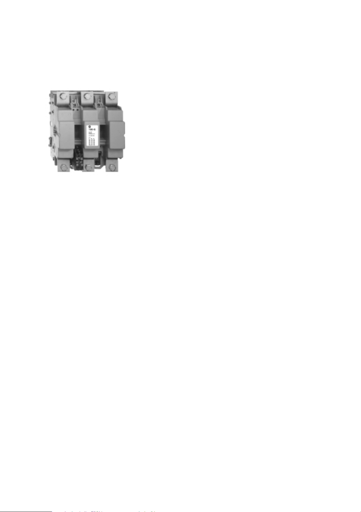
Betriebsvorschrift für Schütze
100-G550, 100-G700 und 100-G860
Operating instructions for contactors
100-G550, 100-G700 and 100-G860
Instructions de service pour contacteurs
100-G550, 100-G700 et 100-G860
Istruzioni per I’impiego dci contattori
100-G550, 100-G700 e 100-G860
UL/cUL Requirements
• Break all lines.
• Suitable for use on a circuit capable of delivering not
more than 18000 RMS symmetrical amperes. 600V
maximum.
• Power terminations: Use 75°C copper conductors only.
Torque terminals to 375 lb-in.
• Max. fuse: 1200 A, Class L
• Max. circuit breaker: 1200 A
D
Allgemeines
Die Schütze 1
•
Schalten von Drehstrommotoren sowie von Verteilungsnetzen bis 690 V~
Betriebsspannung verwendet.
00-G550, 100-G700 und 100-G860 werden hauptsächlich zum
Bauart
• Die Mechanik dieser Schütze ist so ausgelegt, dass der Magnet senkrecht
zur Bewegung der Kontakte arbeitet. Die Prellungen, die durch das
Schliessen des Magnets entstehen, werden daher nicht auf die Kontakte
übertragen. Dies verbessert die Leb ensdauer und das Einschaltvermögen
der Schütze.
Die Schütze
•
um die Schützspulen wahlweise mit Wechsel- bzw. Gleichspannungen bei
niedriger Leistungsaufnahme der Spule ansteuern zu können.
Die Versorgungseinheit bietet die Möglichkeit, den Ausschaltverzug des
Schützes wahlweise auf 0,5—1 s oder 150...200 ms einzustellen. Im Lieferzustand ist des Schütz auf 150...200 ms Ausschaltverzug eingestellt.
•
Die Schütze habe
— 1 Hilfsschalterblock 2 S+2 Ö
— 1 Schattstellungsanzeige
— 1 Erdungsklemme.
• Ausserdem können die Schütze mit umfangreichem Zubehör vom Anwender
bestückt werden:
• 1 zusätzlicher Hilfsschalterblock 2 S + 2 Ö
—4.
— mechanische Verriegelungen
— mechanische Verklinkung.
• Austausch der Spule und der Kontakte ist von der Frontseite her möglich.
sind mit einer elektronischen Versorgungseinheit ausgerüstet,
n:
Pol
EN
Introduction
Contactor ratings 100-G550, 100-G700 and 100-G860 are mainly used for
controlling three phase motors or power circuits up to 690 V A.C.
Construction
• The contactor mechanism is designed so that the magnet system is vertically
operated whereas the contacts are moving in the horizontal plane. This
design prevents that the high operating forces caused by the electro-magnet
system are transmitted towards the co ntacts. Consequently a very low
contact bounce is measured on the main contacts, increasing the contact life
and contactor making capacity.
• The c ontactor control circuit is fed via a feeder group suitable for A.C. 50/60
Hz or D.C. supply, with a low coil consumption value.
The opening time of the contactors can be changed by the user from 0,5...1
sec. into 150...200 ms. The contactors are delivered in the standard version
with «normal drop» (150...200 ms).
• Contactors are equipped with:
— 1 auxiliary contact block 2 N/O + 2 N/C
— «ON-OFF» indicator
— 1 terminal for earth connection.
• In addition, the contactors can be equipped by the user with accessories:
— 1 extra auxiliary contact block 2 N/O + 2 N/C
pole
—4th
— mechanical interlock
— mechanical latch.
• Coil changing and contact replacement is carried out from the front of the
contactor.
4
F
Généralités
Les contacteurs monoblocs calibres 100-G550, 100-G700 et 100-G860 sont
principalement utilisés pour la commande de moteurs triphasés ou de circuits de
distribution jusqu’à 690 V~.
Conception générale
• Le mécanisme de ces contacteurs a été étudié de telle sorte que le sens de
déplacement du circuit magnétique est perpendiculaire à celui des contacts.
Les chocs provoqués par la fermeture du circuit magnétique ne sont donc
pas transmis aux contacts. Ceci améliore la durée de vie et le pouvoir de
fermeture des contacteurs.
• Les co ntacteurs sont équipés d’un module d’alimentation électronique (situé
à la partie haute du contacteur) qui permet de les commander
indifféremment en alternatif 50 ou 60 Hz ou en courant continu, avec une
consommation réduite. Ce module d’alimentation permet à l’utilisateur de
choisir entre des temps d’ouverture de 0,5 à 1 seconde ou de 150 à 200 ms.
Les contacteurs sont livrés en exécution standard avec ouverture
retardée(150...200ms).
• Les contacteurs sont équipés de :
— 1 bloc contacts auxiliaires 2 F + 2 0
— 1 indicateur de fonctionnement
— 1 borne de mise à la terre.
• De plus, ces contacteurs peuvent être équipés d’accessoires montables par
l’utilisateur :
— 1 bloc contacts auxiliaires s upplémentaire 2 F + 2 0
pôle
—4
— verrouillages mécaniques
— accrochage mécanique.
• Changement des bobines et contacts par l’avant de l’appareil.
I
Generalità
I contattori monoblocco tipo 100-G550, 100-G700 e 100-G860 sono
principalmente utilizzati per il comando di motori trifase o di circuiti di
distribuzione fino a 690 V.
Concezione generale
• li meccanismo di questi contattori è stato studiato in modo tale che il
movimento dol circuito magnetico sia perpendicolare a quello dei contatti. Le
vibrazioni provocate dalla chiusura del circuito magnetico non sono quindi
trasmesse ai contatti. Ciô migliora la durata di vita ed il potere di chiusura dei
contattori.
• I contattori sono equipaggiati di un modulo di alimentazione elettronico
(situato nella parte superiore dell’apparecchio) che permette di comandarli
indifferentemente sia in corrente alternata 50 o 60 Hz che in corrente
continua con un assorbimento bobina molto ridotto. Il modulo di
alimentazione consente inoltre all’utilizzatore di scegliere tra i seguenti tempi
di aperture: 0,5—1 sec o 150—200 msec.
I contattori vengono forniti in esecuzione standard con apertura normale
(150...200 ms).
• I contattori sono equipaggiati di:
— 1 blocco di contatti ausiliari 2 NO + 2 NC
— 1 indicatore di stato, aperto o chiusuro, dell’apparecchio
— 1 morsetto di messa a terra.
• Possono inoltre essere corredati dei seguenti accessori montabili a cura
dell’utilizzatore:
— 1 blocco di contatti ausliari supplementare 2 NO + 2 NC
— 4° polo di potenza
— blocco meccanico
— aggancio meccanico.
• Le operazioni di sostituzione bobine e contatti sono eseguibili accedendo
della parte frontale degli apparecchi.
Page 5
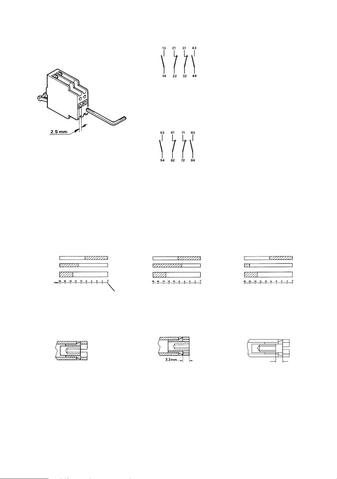
Fig.D
Fig.1
Fig.2
D
Hilfsschalterblock EF 22
Der Hilfsschalterblock EF 22 ist mit 2 S und 2 Ö
bestückt, die galvanisch getrennt sind. Der Einschaltzeitpunkt der Hilfsschliesser gegenüber den
Hauptkontakten kann durch Drehen der Einstellschraube an der Frontseite justiert werden
(siehe Fig. D).
Fig. 1 – Lieferzustand – EF 22 links im Schütz
montiert, zwischen L1 und L2.
Fig. 2 – EF 22 rechts im Schütz montierbar, zwis-
chen L2 und L3.
F
Bloc contact auxiliaire EF 22
Le bloc contact auxiliaire EF 22 est équipé de deux
contacts F et de deux contacts O séparés galvaniquement. La fermeture des contacts auxiliaires F
par rapport aux contacts principaux est réglable au
moyen d’une vis située à l’avant du bloc contact
auxiliaire (voir fig. D).
Fig. 1 – EF 22 monté à gauche sur le contacteur,
entre Li et L2. Ce bloc est livré avec le con
tacteur.
Fig. 2 – EF22 monté à d roite sur le contaceur,
entre L2 et L3. Ce b loc e st livré
séparément, en accessoire.
Standard Ausführung
Exécution standard
EF 22
Schütz
Contacteur
Standard Stellung der Einstellschraube
Position standard de la vis de réglage
Überlappung S-Ö
Chevauchement F-O
Ö/O
S/F
EF 22
Schütz
Contacteur
S t e l l u n g « O F F E N »
Position «OUVERT»
Schraube um 4 Drehungen herausdrehen
Dévisser la vis de 4 tours
Ö/O
S/F
Schliesser verzögert
Fermeture retardée
EF 22
Schütz
Contacteur
3,2 mm63,2 mm
Schraube um 4 Drehungen hineindrehen
Visser la vis de 4 tours
Ö/O
S/F
5
Page 6

Fig.D
Fig.1
Fig.2
EN
Auxiliary contact type EF 22
EF 22 auxiliary contact block provides 2 NO and
2 NC auxiliary contacts mutually insulated up to
690 V. NO contacts position related to the main
poles can be regulated by the user screwing or
unscrewing the adjustable scr ew shown on the
contact block front (see Fig. d).
Fig. 1 — EF 22 fitted L.H.S. on the contactor
(between L1 and L2) delivered with the
contactor.
Fig. 2 — EF22 for fitting R.H.S.on the contactor
(between L2 and L3) delivered separate
as accessory.
I
Blocco di contatti ausiliari EF 22
II blocco di contatti ausiliari EF 22 è costituito da
2 contatti NO e da 2 contatti NC separati galvanicamente. La chiusura dei contatti ausiliari NO rispetto ai contatti priocipali è regolabile per mezzo di
un grano situato sulla parte frontale del blocco di
contatti.
Fig. 1 — EF 22 montato a sinistra sulcontattore tra
le tasi Li e L2. Questo blocco viene fornito con il contattore.
Fig. 2 — EF 22 montato a destra sul contattore tra
le fasi 12 e L3. Questo blocco viene fornito su richiesta.
Standard configuation
Regolazione di normale fornitura
EF 22
Contactor
Contallore
Standard position of reulation screw
Posizione grano dí regolazione
NC
NO
EF 22
Contactor
Contallore
«OPEN» position
Posizione «APERTO»
Overlaping configuration
Regolazione con NO-NC in
sovrapposizione
NC
NO
Regulation screw position (unscrew by 4 turns)
Posizione grano di regolazione
(svitare il grano di 4 gin)
NO delayed configuration
Regolazione con NO ritardato
EF 22
Contactor
Contallore
Regulation screw position (screw by 4 turns)
Posizione grano di regolazioe
(avvitare il grano di 4 girl)
NC
NO
Page 7

100-G550
DELAYED DROP NORMAL DROP
1AC-2AC
+
34
13 5
C1
A1 A2 M1 M2
CC
NC
NO
Y
Y
NO
NC
246
135
C
246
13 21 31 43
14 22 32 44
53 61 71 83
54 62 72 84
YY
A1 A2
12
3
C1
4
C
C
M1
M2
C: Schütz - Contacteur - Contactor - Contattore
C1: Verzögerter «Ö» Kontakt EG01 - Contact «O» retardé EG01 - EG01
delayed NC contact - Contatto NC ritardato EG01
Y: Hilfsschalter EF 22 - Contact auxiliaire EF 22 - EF 22 auxiliary contact
- Contatto ausiliario EF 22
100-G700/100-G860
D
Elektrisches Schaltbild
Das Schütz wird so ausgeliefert, dass eine normale Ausschaltzeit (150…200 ms)
erreicht wird. Ferner hat der Benützer jedoch die Möglichkeit, das Gerät auf eine
Ausschaltverzögerung (0,5…1 s) umzubauen. In dieser Konfiguration ist es im
geschlossenen Zustand geschützt gegen kurzzeitige Spannangsabsenkungen
und unsichere Kontakatabgabe in der Ansteuerung der Spule. Um das Schütz auf
Ausschaltverzögerung zu modifizieren, sind folgende Änderungen durchzuführen
(mit isoliertem Haupt- und Steuerstromkreis zu verrichten):
• Die Einspeiseabdeckung demontieren.
• 100-G550: Den Draht (+) von der Klemme « NORMAL DROP » lösen und an
der Klemme « DELAYED DROP » anschliessen.
• 100-G700/100-G860: Den Draht (Z+) vom positiven Pol des Gleichrichters
und den Draht (+) vom Draht (Z-) lösen; nachher den Draht (+) am positiven
Pol der Diode und den Draht (Z+) am Draht (Z-) wieder anschliessen. Nur bei
den Schützen mit 48V Steuerspannung muss auch die Diode « D » (welche
bereits mit dem positiven Pol der Gleichrichters verbunden ist) zwischen dem
+ und - Pol der Gleichrichterbrücke angeschlossen werden (zu diesem Zweck
Schutzchild der Diode abheben).
• Einspeiseabdeckung wieder montieren.
F
Schéma électrique
Le contacteur est livré déjà précâblé de façon à ce que son temps déclenchement
atteigne sa valeur normale (150…200 ms). Ultérieurement, l’utilisateur a la
possibilité de modifier l’appareil afin d’augmenter la temporisation à l’ouverture
(0,5…1 s). Dans ces conditions et en position fermée, le contacteur reste donc
insensible aux brèves chutes de tension sur le des bornes d’alimentation. Rèseau
et aux micro-coupures pouvant être provoquées par les contacts placés dans le
circuit de commande de la bobine. Pour modifier la temporisation au
déclenchement du contacteur, il faut effectuer les opérations suivantes (à
exécuter avec circuit principal et de commande isolés).
• Retirer le couvercle de protections des bornes d’alimentation.
• 100-G550: Déconnector le fil (+) de la borne « NORMAL DROP » et le
brancher sur la borne « DELAYED DROP ».
• 100-G700/100-G860: Déconnector le fil (Z+) du pôle positif du redresseur
ainsi que le fil (+) du fil (Z-); ensuite reconnecter le fil (+) sur le pôle positif de la
diode et raccorder le fil (Z+) au fil (Z-). Seulement dans le cas de contacteurs
avec une tension de commande de 48V, il faut également connecter la diode «
D » (laquelle est déjà raccordée sur le pôle positif du redresseur) entre les
pôles + et - du pont redresseur (pour cela, enlever le couvercle de protection
de la diode).
• Replacer le couvercle de protection de bornes d’alimentation.
135
C
246
13 21 31 43
14 22 32 44
53 61 71 83
54 62 72 84
YY
A1 A2
C1
VDR
1RT
2
Z
D
M1
M2
C
C
1~ 2~
RT
Z
VDR
2AC
1AC
+-
D
Z+
13 5
C1
456
R
-
A1 A2 M1 M2
R
Z+ -
CC
NC
NO
Y
Y
NO
NC
R
C: Schütz - Contacteur - Contactor - Contattore
C1: Verzögerter «Ö» Kontakt EG01 - Contact «O» retardé EG01 - EG01
delayed NC contact - Contatto NC ritardato EG01
Y: Hilfsschalter EF 22 - Contact auxiliare EF 22 - EF 22 auxiliary contact
- Contatto ausiliario EF 22
RT: Gleichrichter - Redresseur - Rectifier - Raddrizzatore
VDR: Schutzvorrichtung (für Spannungen über 415 V werden 2 VDR in
Reihe geschaltet) Dispositif de protection (pour tensions supérieures à 415 V, il y a 2
VDR en série) Protection device (over 415 V there are two VDR in series) - Dispositivo di protezione (per tensioni superiori a 415 V ci sono 2 VDR in
serie)
R: Sparwiderstand - Résistance d'économie - Saving resistor - Resist-
enza di risparmio
Z: Vorrichtung für kurzen Ausschaltverzug - Dispositif d'ouverture rapide
- Quick drop device - Dispositivo per rilascio pronto
D: Diode (montiert bis 135 V Betätigungsspannung) - Diode (montée
pour tension de commande jusqu'à 135 V) - Diode (fitted up to 135 V
control voltage) - Diodo (montato solo per tensioni fino a 135 V)
EN
Electrical diagram
The contactor is normally wired so to have a normal dropout time (150…200 ms
abt). Furthermore, it features the ability to be arranged by the user with a delayed
dropout time (0,5…1 s abt). In this configuration, in a sealed condition, the
contactor is insensitive to short time fall and fluctuation of control voltage or
control device instability. To arrange the contactor for the delayed dropout the
following operations are necessary (to be performed with main and control circuit
insulated):
• Lift the feeder group cover.
• 100-G550: Disconnect wire (+) from «NORMAL DROP» terminal and connect
it to «DELAYED DROP» terminal.
• 100-G700/100-G860: Disconnect wire (Z+) from rectifier positive pole and
wire (+) from wire (Z-); Reconnect wire (+) to rectifier positive pole and wire
(Z+) to wire (Z-). For 48 V control voltage contactors only, connect also diode
« D » (which is already connected to rectifier positive pole) across + and poles of the rectifier bridge (remove the protective sheath of diode).
• Put back the feeder cover.
I
Schema elettrico
II contattore è normalmente collegato per avere un tempo di rilascio normale
(150…200 ms circa). E’inoltre possible predisporto, a cura dell’utilizzatore, con un
tempo di rilascio ritardo (0,5…1 s circa) ed in queste condizioni, quando è chiuso,
il contattore è insensibilie a brevi mancanze e fluttuazioni della tensione di
comanda o ad instabilità di dispositivi di contollo. Per predisporre il contattore
con il rilascio ritardato sono necessarie le seguenti operazioni (da eseguire con il
circuito principalee di comando isolati):
• Sollevare il coperchio alimentatore.
• 100-G550: scollegare il filo (+) dal terminale «NORMAL DROP» e collegarlo al
terminale «DELAYED DROP».
• 100-G700/100-G860: scollegare il filo (Z+) dal polo positivo del raddrizzatore
e il filo (+) dal filo (Z-). Solo per i contattori con tensione di comando 48 V,
collegare anche il diodo « D » (che è già precollegato al polo positivo del
raddrizzatore) tra i poli + e - del ponte raddrizzatore (rimuovere la guaina
protettiva).
• Risposizionare il coperchio alimentatore.
7
Page 8

D
Zubehör
Das Zubehör wird getrennt geliefert und muss vom Anwender angebaut werden.
Beschreibung Typ/ Gewicht Verp.
Hilfsschalterblock
2 S + 2 Ö - Ith = 16 A
«S» Kontakte einstellbar
1 zusätzlicher
Hilfsschalterblock
nachrüstbar pro Schütz 100-EF22 0,13 1
4. Pol (Schalten des Nulleiters)
für 100-G550/ Ith = 500 A 100-NP500-5 1,35 1
für 100-G700/ Ith = 500 A 100-NP500-6 1,35 1
für 100-G860/ Ith = 1000 A 100-NP1000-6 1,45 1
Mechanische Verriegelung
zwischen 2 Schützen
100-G550 oder 100-G700
oder 100-G860
übereinander montiert 100-MC00-5V 0,85 1
•
nebeneinander montiert 100-MC00-5H 0,85 1
•
übereinander montiert 100-MC00-56V 0,95 1
•
nebeneinander montiert 100-MC00-56H 0,95 1
•
übereinander montiert 100-MC00-6V 11
•
nebeneinander montiert 100-MC00-6H 1,5 1
•
Mechanische Verklinkung
für Schütz
100-G550 100-FLAM-5 1,3 1
100-G700/100-G860 100-FLAM-6 1,4 1
Die mit jedem Zubehör mitgelieferte Betriebsvorschrift beinhaltet die zum Anbau
an die Schütze notwendigen Hinweise, sowie das Massbild des Schützes mit
angebautem Zubehör.
Bestell-Nr. einheit
kg
F
Accessoires
Les accessoires sont livrés non montés sur les contacteurs. Leur montage doit
être effectué par l'utilisateur.
Description Type/No. de Poids Vente
Bloc contacts auxiliaires
2 F + 2 O - Ith = 16 A
contacts «F» réglables
Adjonction d'un bloc
supplémentaire
sur les contacteurs 100-EF22 0,13 1
e
pole (coupure du neutre)
4
pour 100-G550 Ith = 500 A 100-NP500-5 1,35 1
pour 100-G700/ Ith = 500 A 100-NP500-6 1,35 1
pour 100-G860 Ith = 1000 A 100-NP1000-6 1,45 1
Verrouillages mécaniques
entre 2 contacteurs
100-G550 ou 100-G700
ou 100-G860
montage superposé 100-MC00-5V 0,85 1
•
montage côte à côte 100-MC00-5H 0,85 1
•
montage superposé 100-MC00-56V 0,95 1
•
montage côte à côte 100-MC00-56H 0,95 1
•
montage superposé 100-MC00-6V 1 1
•
montage côte à côte 100-MC00-6H 1,5 1
•
Accrochage mécanique
pour contacteur
100-G550 100-FLAM-5 1,3 1
100-G700/100-G860 100-FLAM-6 1,4 1
La notice d'instruction, livrée avec chaque accessoire, contient les informations
nécessaires pour leur montage sur les contacteurs et les encombrements des
ensembles contacteur(s) + accessoire(s).
commande indivisible
kg par
EN
Accessories
Accessories are supplied separate for fitting by the user.
Description Type/ Weight Pack
Auxiliary contact block
2 N/O + 2 N/C - Ith = 16A
« N/O» contacts adjustable
addition
of one extra block
on contactors 100-EF22 0,13 1
4th pole (neutral switching)
for 100-G550 Ith = 500 A 100-NP500-5 1,35 1
for 100-G700/ Ith = 500 A 100-NP500-6 1,35 1
for 100-G860 Ith = 1000 A 100-NP1000-6 1,45 1
Mechanical interlocks
between 2 contactors
100-G550 or 100-G700
or 100-G860
vertical mech. interlock 100-MC00-5V 0,85 1
•
horizontal mech. interlock 100-MC00-5H 0,85 1
•
vertical mech. interlock 100-MC00-56V 0,95 1
•
horizontal mech. interlock 100-MC00-56H 0,95 1
•
vertical mech. interlock 100-MC00-6V 11
•
horizontal mech. interlock 100-MC00-6H 1,5 1
•
Mechanical latch
for contactors
100-G550 100-FLAM-5 1,3 1
100-G700/100-G860 100-FLAM-6 1,4 1
Accessories are supplied with individual instruction leaflets giving mounting details
and dimensions of contactor (s) c/w accessorie (s).
Ordering no. Qty
kg
I
Accessori
Gli accessori sono forniti a parte ed il loro montaggio sul contattore deve essere
effettuato dall'utilizzatore.
Descrizione Tipo/ Peso Q.tà
Blocco di contatti ausiliari
2 NO + 2 NC - Ith = 16A
Contatti « NO» regolabili
Aggiunta di un blocco
supplementare sui contattori 100-EF22 0,13 1
4e polo (di sezionamento
del neutro)
per 100-G550 Ith = 500 A 100-NP500-5 1,35 1
per 100-G700/ Ith = 500 A 100-NP500-6 1,35 1
per 100-G860 Ith = 1000 A 100-NP1000-6 1,45 1
Interblocco meccanico
tra 2 contattori
100-G550 o 100-G700
o 100-G860
esecuzione verticale 100-MC00-5V 0,85 1
•
esecuzione orizzontale 100-MC00-5H 0,85 1
•
esecuzione verticale 100-MC00-56V 0,95 1
•
esecuzione orizzontale 100-MC00-56H 0,95 1
•
esecuzione verticale 100-MC00-6V 11
•
esecuzione orizzontale 100-MC00-6H 1,5 1
•
Aggancio meccanico
per contattori
100-G550 100-FLAM-5 1,3 1
100-G700/100-G860 100-FLAM-6 1,4 1
Le istruzioni di servizio sono fornite con gli accessori e riportano le informazione
necessarie per il loro montaggio sul contattore unitamente ai disegni di ingombro
dell’insieme contattore/i accessorio/i.
N. di ordine min.
kg indivis.
8
Page 9

Satz von 2 Ersatzspulen
Jeu de 2 bobines
100-G550
100-G700/100-G860
D
Austauschen der Spulen
Weil das Schütz mit 2 in Reihe geschalteten Spulen
bestückt ist, müssen diese 2 Spulen zusammen
ausgetauscht werden.
Bestellangaben für Standard-Spulen
Spannungen 1) Typ/ Verp.-
VAC V DC
110...120 100...110 TX 734 1 Satz
220...240 200...220 TX 747 1 Satz
380...415 345...380 TX 779 1 Satz
440...480 400...440 TX 780 1 Satz
110...120 100...110 TY 734 1 Satz
220...240 200...220 TY 747 1 Satz
380...415 345...380 TY 779 1 Satz
440...480 400...440 TY 780 1 Satz
1
) Die Spulen können sowohl bei 50 und 60Hz als
auch bei Gleichspannung ve rwendet werden.
Anmerkung: Wenn die Steuerspannung geändert
Andere Spannungen: auf Anfrage.
Bestell-Nr. einheit
wird, müssen die Spulen und die
Versorgungseinheit ausgetauscht
werden.
F
Échange des bobines
Les contacteurs étant équipés de 2 bobines branchées en série, il faut systématiquement procéder à
l'échange des 2 bobines.
Références de commande des bobines standard
Tensions 1) Type/No. de Vente
V AC VDC par
110...120 100...110 TX 734 1 jeu
220...240 200…220 TX 747 1 jeu
380...415 345...380 TX 779 1 jeu
440...480 400...440 TX 780 1 jeu
110...120 100...110 TY 734 1 jeu
220...240 200...220 TY 747 1 jeu
380...415 345...380 TY 779 1 jeu
440...480 400...440 TY 780 1 jeu
1
) Les tensions en alternatif sont valables en 50 Hz
et en 60 Hz. Les bobines peuvent être alimentées
indifféremment en alternatif et en continu.
Nota: Dans le cas d'un changement de la tension
de commande il faut échanger les bobines et
le module d'alimentation.
Autres tensions : nous consulter.
commande indivis.
Démontage
Fig. 1 Fig. 2
Fig. 3
Fig. 4
Montage
Fig. 5
Fig. 7
Fig. 6
Fig. 8
D
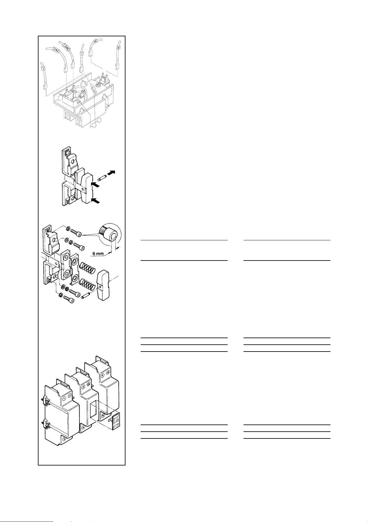
Montage-Anleitung für Auswechseln der Spulen
— Steuerstromkreis und Hauptstromkreis ausschalten.
— Schaltkammer abnehmen und Deckel der Versorgungseinheit öffnen (Fig. 1).
— Mit einem Schraubendreher wie in Fig. 2 dargestellt, den beweglichen Magnet
etwas anheben, und wie in Fig. 3 dargestellt, vorsichtig nach oben drücken,
ohne ihn ganz herauszunehmen.
— Die 4 Befestigungsschrauben der Spulen herausdrehen (Fig. 4), die Spulen an
den Handgriffen um 5 mm anheben und aus dem Schütz ziehen.
— Den Magnet hochgehoben lassen, die neuen Spulen einsetzen (Fig. 5).
— Bevor man die 4 Spulen-Befestigungsschrauben fest anzieht, nachprüfen ob
der untere Magnet richtig in den Spulen sitzt, Die Hauptkontakte von Hand
schliessen um zu überprüfen, ob sich das System frei bewegt (Fig. 6). Wenn
nicht, den unteren Magnet ein wenig bewegen (Fig. 6).
— Dann den oberen Magnet wieder in seine Arbeitsposition drücken (Fig. 7).
— Die 4 Befestigungsschrauben der Spulen fest anziehen (Fig. 8).
Anmerkung: Bevor man den Deckel der Versorgungseinheit wieder schliesst
und das Schütz wieder unter Spannung setzt, nachprüfen ob die
Spannung auf den Spulen mit der Spannung auf der
Versorgungseinheit übereinstimmt.
F
Instructions pour le remplacement des bobines :
— S'assurer que l'appareil est hors tension.
— Dévisser et enlever la chambre de coupure, soulever le couvercle du module
d'alimentation (fig. 1).
— Positionner la lame d'un tournevis et commencer à soulever le circuit
magnétique (fig. 2).
— Pour soulever à fond le circuit magnétique, placer la lame du tournevis suivant
fig. 3 et appuyer à fond, sans toutefois sortir le circuit de l'appareil.
— Dévisser les 4 vis de fixation des bobines (fig. 4) ; agripper les bobines par les
supports de vis de fixation, soulever les bobines de 5 mm environ et les
extraire du contacteur
— Le circuit magnétique étant maintenu soulevé, remettre en place les nouvelles
bobines en effectuant l'opération inverse (fig. 5).
— Avant de bloquer les 4 vis de fixation des bobines, s'assurer que la partie
basse du circuit magnétique, située en-dessous des bobines, est cor-
rectement engagée dans celles-ci : actionner l'ensemble contacts mobiles et
s'assurer que l'appareil fonctionne correctement (fig. 6). Dans la négative,
orienter la partie basse du circuit magnétique en actionnant l'un des becs
d'accrochage des contacts auxiliaires (fig. 6).
— Ramener le circuit magnétique à sa position normale de fonctionnement en le
poussant vers le bas (fig. 7).
— Serrer les 4 vis de fixation des bobines (fig. 8).
Nota : Avant de remettre en place le couvercle du module d'alimentation et la
chambre à couper et, avant de mettre le contacteur sous tension, vérifier
que la tension de commande est compatible avec celle indiquée, à la
fois, sur les bobines et sur le module d'alimentation.
9
Page 10

Set of 2 coils for 1 cont actor
Set di 2 bobine per 1 contattore
100-G550
100-G700/100-G860
EN
Coil Changing
The contactors are equipped with 2 coils series
connected and both coils have to be changed.
Ordering details for standard coils
Voltages 1) Type/ Pack
V A.C. V D.C.
110...120 100...110 TX 734 1 set
220...240 200...220 TX 747 1 set
380...415 345...380 TX 779 1 set
440...480 400...440 TX 780 1 set
110...120 100...110 TY 734 1 set
220...240 200...220 TY 747 1 set
380...415 345...380 TY 779 1 set
440...480 400...440 TY 780 1 set
1
) A.C. voltage values are valid for both 50 Hz and
60 Hz. Coils can be fed on A.C. or D.C.
Note: In case of a change in the control voltage
supply which would require a coil
changing, change the feeder group too.
Other voltages; please consult.
Ordering No. Qty
I
Cambio bobine
I contattori sono forniti con 2 bobine collegate in
serie. In caso di sostituzione è necessario
cambiarle entrambe.
Tabella bobine
Tensioni 1) Tipo/ Q.tà
V AC V DC indivis.
110...120 100...110 TX 734 1 set
220...240 200...220 TX 747 1 set
380...415 345...380 TX 779 1 set
440...480 400...440 TX 780 1 set
110...120 100...110 TY 734 1 set
220...240 200...220 TY 747 1 set
380...415 345...380 TY 779 1 set
440...480 400...440 TY 780 1 set
1
) I valori in AC sono validi a 50 Hz e 60 Hz. Le
bobine possono essere alimentate
indifferentemente in AC e DC.
Nota: Qualora si cambi la tensione d’alimenta-
zione è necessario sostituire le bobine e
l’alimentatore.
Altre tensioni: consultarci.
N. di ordine min.
Dismantling/Smontaggio
Fig. 1 Fig. 2
Fig. 3
Fig. 4
Mounting/Montaggio
Fig. 5
Fig. 6
Instructions for changing the two coils
— Isolate main and control voltage.
— Take off the arc chute and lift the feeder cover (fig. 1 ).
— lnsert a screwdriver in the hole of plastic piece jointed to the upper core and
start lifting the core (fig. 2).
— Then lift the core completely acting upon the screwdriver (fig. 3).
— Unscrew the 4 coil fastening screws (fig. 4). By keeping the core lifted (fig. 4),
lift the coils by means of the proper front handles of about 5 mm and take them
from the contactor.
— Keeping the core lifted, fit the new coils (fig. 5).
— Before tightening the 4 coils fastening screws check that the lower core is
properly fitted in the coils. Press the main voltage contacts by hand to close
and check that the assembly moves freely (fig. 6). Otherwise it is necessary to
slightly mov e the lower core (Fig. 6).
— Refit the upper core into standard working position by pressing it downwards
(fig. 7).
— Tighten the 4 coil fastening screws (fig. 8).
Note: Before putting back the feeder group cover plus the arc chute and
energizing the contactor, check that the control voltage suits that one
indicated both on the coils and on the feeder group.
I
Istruzioni per la sostituzione delle bobine
— Togliere tensione al circuito di comando e di potenza.
— Togliere il parafiamme e sollevare il coperchio del modulo d'alimentazione
(fig. 1).
— Inserire un cacciavite nel foro della parte in plastica solidate con il nucleo
superiore ed iniziare a sollevare il nucleo (fig. 2).
— Sollevare poi completamente il nucleo facendo leva con il cacciavite come
indicato in fig. 3.
— Svitare le 4 viti di fissaggio e collegamento delle bobine (fig. 4). Tenendo
sollevato il nucleo (fig. 4) prendere le bobine da lle apposite appendici frontali e
alzarle di circa 5 mm; indi sfilarle dal contattore.
— Montare le nuove bobine (fig. 5).
— Prima di serrare le 4 viti di fissaggio delle bobine, assicurarsi che il nucleo
inferiore sia inserito correttamente nelle bobine stesse. A questo s copo,
spingere con le mani i contatti mobili nella direzione di chiusura e verificare
che l'equipaggio sia libero nel movimento (fig. 6). In caso contrario è
necessario smuovere leggermente il nucleo inferiore (fig. 6).
— Reinserire, spingendo verso il basso, il nucleo superiore nella normale
posizione di lavore (fig. 7).
— Bloccare le 4 viti di fissaggio delle bobine (fig. 8).
Nota: Prima di riposizionare il coperchio del modulo di alimentazione e
parafiamme e, prima di mettere il contattore sotto tensione, verificare che
la tensione di alimentazione sia compatibile con quella indicata sulle
bobine e sull'alimentatore.
EN
10
Fig. 7
Fig. 8
Page 11

100-G550
delayed drop
delayed drop normal drop
1AC-2AC
TXS...
+
34
normal drop
D
Versorgungseinheit
• Die Versorgungseinheit ermöglicht es, die
Schützspulen wahlweise mit Wechselspannungen 50 Hz oder 60 Hz, bzw. Gleichspannungen
zu betätigen. Zu jeder Spulenspannung gehört
eine besondere Versorgungseinheit.
Anmerkung: Wenn die Steuerspannung
• Die Versorgungseinheit bietet die Möglichkeit,
den Ausschaltverzug des Schützes wahlweise
auf 0,51 s oder 150-200 ms einzustellen.
— verzögerter Ausschaltverzug «delayed
— kurze Abfallzeit, «normal drop» (auf der
Die Geräte werden in Stellung «normal drop»
geliefert. Umstellung auf «delayed drop» muss
durch den Anwender erfolgen (die mit (+)
gekennzeichnete Leitung von «nor mal drop»
Stellung auf «delayed drop»» umstecken).
• Der Austausch der Versorgungseinheit erfolgt
durch Austauschen des Deckels auf der Oberseite des Schützes, nachdem man die
Leitungen 1, 2, 3, 4, +, -, abgezogen hat.
Steuerspannung und Hauptstromkreis müssen
dabei ausgeschaltet sein.
Bestellangaben für Standard-Spulen
Spannungen Typ/ Verp.-
V AC V DC
110...120 100...110 TXS 734 1
220...240 200...220 TXS 747 1
380...415 345...380 TXS 779 1
440...480 400...440 TXS 780 1
geändert wird, müssen die
Versorgungseinheit und die
Spulen ausgetauscht werden.
drop» (auf der Versorgungseinheit
gekennzeichnet) von 0,5 a bis 1 Sekunde.
Versorgungseinheit gekennzeichnet) von
150 bis 200 ms.
Bestell-Nr. einheit
F
Module d'alimentation
Le module d'alimentation permet d'alimenter,
indifféremment, la bobine du contacteur en
alternatif 50 ou 60Hz ou en courant continu. A
chaque tension bobine correspond un module
d'alimentation.
Nota : Dans les cas d'un changement de la
tension de commande, il faut changer le module d'alimentation et les
bobines.
• Le module d'alimentation offre à l'utilisateur le
choix entre 2 temps d'ouver ture du contacteur
— ouverture retardée, marquée « delayed
drop » sur le module d'alimentation:
de 0,5 s à 1 seconde.
— ouverture rapide, marquée « normal drop »
sur le module d'alimentation : de 150 a 2 00
ms.
Les appareils sont livrés en position « normal
drop ». Le changement on « delayed drop »
est à réaliser par l'utilisateur (brancher le fil (+)
de « normal drop » sur la borne (+)
de « delayed drop »).
• L'é change du module d'alimentation se fait par
échange du couvercle situé sur le haut du
contacteur, après avoir déconnecté les fils 1, 2,
3, 4, + et les circuits de commande et de
puissance étant hors tension.
Références de commande pour
tensions standard
Tensions Type/No. de Vente
V AC V DC
110...120 100...110 TXS 734 1
220...240 200...220 TXS 747 1
380...415 345...380 TXS 779 1
440...480 400...440 TXS 780 1
commande in divis.
100-CP550
100-AC550
Ersatzkontakte
Um ein dreipoliges Schütz komplett neu zu
bestücken, benötigt man 3 Sätze Ersatzkontakte.
1 Satz besteht aus: 2 Festkontakten und dem
beweglichen Kontakt wie nebenstehend
dargestellt.
Bestellangaben für 1 Satz Ersatzkontakte
Für Schütz Typ/ Verp.-
Typ
100-G550 100- CP550 1 Satz
Bestell-Nr. einheit
Lichtbogenkammer
Die Lichtbogenkammer enthält die Löschbleche;
sie wird geliefert mit:
— 2 unverlierbaren Befestigungsschrauben
Bestellangaben
Für Schütz Typ/ Verp.-
Typ
100-G550 100- AC550 1
Bestell-Nr. einheit
Pôles de rechange
Pour équiper 1 contacteur tripolaire complet il faut
approvisionner 3 jeux de contacts principaux.
Chaque jeu de contacts comprend les contacts
fixes et mobiles et accessoires de montage, selon
le schéma ci-contre.
Références de commande du jeu de contacts
Pour Type/ Vente
contacteur No. de commande inType divis.
100-G550 100- CP550 1 jeu
Chambre de coupure
La chambre de coupure est équipée des grilles de
soufflage. Elle est livrée avec :
— 2 vis de fixation imperdables
Références de commande
Pour Type/ Vente
contacteur No. de commande inType divis.
100-G550 100- AC550 1
11
Page 12

100-G550
delayed drop
delayed drop normal drop
delayed drop
1AC-2AC
TXS...
+
34
normal drop
normal drop
EN
Feeder group
• The feeder group is suitable for A.C. 50 or 60
Hz or D.C. supply and has to be selected
according to the supply voltage in force.
Note: In case of a change in the control
voltage supply which would require
a coil changing, the feeder group
has to be changed too.
• The feeder group is designed so that the user
can select the contactor opening times as
follows:
— «delayed drop» 0,5 to 1 sec. See
— -«normal drop» 150 to 20 0 ms. on the
Contactors are delivered in the standard version with «normal drop». Conversion into
«delayed drop» can be achieved by the user
(disconnect wire (+) from «normal drop» and
reconnect if onto «delayed drop» terminal marked (+).
• The feeder group is located at the upper part of
the contactor and can be removed once the
wire 1, 2, 3, 4, +, -, are disconnected as well as
the main and control circuits.
Ordering details for standard voltage
Voltages Type/ Pack
V A.C. V D.C.
110...120 100...110 TXS 734 1
220...240 200...220 TXS 747 1
380...415 345...380 TXS 779 1
440...480 400...440 TXS 780 1
Ordering no. Qty
marking
feeder group
I
Modulo di alimentazione
• Il modulo di alimentazione permette di
comandare le bobine del contattore,
indifferentemente, in corrente alternata 50-60
Hz o in corrente continua. A ciascuna tensione
della bobina corrisponde un modulo di
alimentazione.
Nota: In caso di modifica della tensione di
comando è necessario cambiare il
modulo di alimentazione e le
bobine.
• Il modulo di alimentazione permette
all'utilizzatore di scegliere tra 2 tempi
d'apertura del contattore:
— apertura ritardata identificata come
«delayed drop» sul modulo
d'alimentazione:
da 0,5 sec a 1 sec.
— apertura rapida identificata come «normal
drop» sul modulo d'alimentazione:
da 150 a 200 msec.
Gli apparecchi sono forniti con apertura normale (150...200 ms); la modifica del tempo di
apertura può essere fatta a cura
dell'utilizzatore (collegare il cavo (+) di «normal
drop » su morsetto (+) di «delayed drop» ).
• La sostituzione del modulo d'alimentazione
può essere fatta cambiando il co perchio situato sulla parte superiore del contattore, dopo
aver scollegato i cavi 1, 2, 3, 4, + e-; durante
questa operazione i circuiti di comando e di
potenza non devono essere sotto tensione.
Riferimenti di ordinazione per tensioni
standard
Tensioni Tipo/ Q.ta
V AC V DC ordine divis.
110...120 100...110 TXS 734 1
220...240 200...220 TXS 747 1
380...415 345...380 TXS 779 1
440...480 400...440 TXS 780 1
N. di min. in-
100-CP550
100-AC550
Spare parts - main poles
One contactor requires 3 sets of main contacts.
Each contact set comprises the fixed and moving
contacts and fixing parts as shown on the opposite
sketch.
Ordering details for one contact set
Contactor Type Pack
rating Ordering no. Qty
Typ e
100-G550 100- CP550 1 set
Spare parts - arc chute
The arc chute c/w blow out grids and:
— 2 captive fixing screws
Ordering details
Contactor Type/ Pack
rating Ordering no. Qty
Typ e
100-G550 100- AC550 1
Poli di ricambio
Per equipaggiare un contattore tripolare completo
è necessario ordinare 3 set di contatti principali,
ciascun set comprende 2 contatti fissi, 1 contatto
mobile e gli accessori di montaggio come mostrato nella figura a lato.
Riferimenti di ordinazione di un corredo polo
completo
Contattore Tipo/ Q.ta
Tipo divis.
100-G550 100- CP550 1 cor. p.
N. di ordine min. in-
Parafiamme
Il parafiamme è equipaggiato di lamelle per
frazionamento dell'arco elettrico. Viene fornito
completo di:
— 2 viti di fissaggio imperdibili
Riferimenti di ordinazione
Contattore Tipo/ Q.ta
Tipo divis.
100-G550 100- AC550 1
N. di ordine min. in-
12
Page 13

100-G700/100-G860
TYS...
D
Versorgungseinheit
• Die Versorgungseinheit ermöglicht es, die
Schützspulen w ahlweise mit
Wechselspannungen 50 Hz oder 60 Hz, bzw.
Gleichspannungen zu betätigen. Zu jeder
Spulenspannung gehört eine besondere
Versorgungseinheit
Anmerkung: Wenn die Steuerspannung
Z-
Z+
• Die Versorgungseinheit bietet die Möglichkeit,
den Ausschaltverzug des Schützes wahlweise
auf 0,5-1 s oder 150-200 ms einzustellen.
— kurze Abfallzeit, «normal drop» (auf der
— verzögerter Ausschaltverzug «delayed
Die Geräte werden in Stellung «normal drop»
geliefert. Umstellung auf «delayed drop» muss
durch den Anwender erfolgen: Leitung (Z+)
vom Gleichrichter abziehen, Leitung (+) an
positiven Pol des Gleichrichters anschliessen
und Leitungen (Z-) und (Z+) verbinden. Bei
Schützen mit 48 V Spulenspannung nur Diode
D abschalten (siehe Seite 4).
• Der Austausch der Versorgungseinheit erfolgt
auf der Oberseite des Schützes, nachdem
man die Leitungen 1, 2, R, +, -, abgezogen hat.
Steuerspannung und Hauptstromkreis müssen
dabei ausgeschaltet sein.
Bestellangaben für Standard-Spulen
Spannungen Typ/ Verp.
V AC V DC
110...120 100...110 TYS 734 1
220...240 200...220 TYS 747 1
380...415 345...380 TYS 779 1
440...480 400...440 TYS 780 1
geändert wird, müssen die
Versorgungseinheit und die
Spulen ausgetauscht werden.
Versorgungseinheit gekennzeichnet) von
150 bis 200 ms.
drop» (auf der Versorgungseinheit
gekennzeichnet) von 0,5 s bis 1 Sekunde.
Bestell-Nr. einheit
Module d'alimentation
• Le module d'alimentation permet d'alimenter,
indifféremment, la bobine du contacteur en
alternatif 50 ou 60 Hz ou encourant continu. À
chaque tension bobine correspond un module
d'alimentation.
Nota : Dans les cas d'un changement de la
tension de commande, il faut changer le module d'alimentation et les
bobines.
• Le module d'alimentation offre, à l'utilisateur, le
choix entre 2 temps d'ouverture du contacteur :
— ouverture rapide, marquée « normal drop »
sur le module d'alimentation :
de 150 à 200 ms.
— ouverture retardée, marquée « delayed
drop » sur le module d'alimentation :
de 0,5 s à 1 seconde.
Les appareils sont livrés en position « normal
drop ». Le changement en « delayed drop »
est à réaliser par l'utilisateur : déconnecter le fil
(Z+) du redresseur, brancher le fil (+) sur la
borne (+) du redresseur et les fils (Z-) et (Z+)
l'un avec l'autre. Sur les contacteurs prévus
pour une tension de commande de 48 V,
débrancher uniquement la diode D (voir page
4).
• L'échange du module d'alimentation se fait par
le haut du contacteur, après avoir déconnecté
les fils 1, 2, R, + et -, les circuits de commande
et de puissance étant hors tension.
Références de commande pour tensions
standard
Tensions Type/No. de Vente
V AC V DC
110...120 100...110 TYS 734 1
220...240 200...220 TYS 747 1
380...415 345...380 TYS 779 1
440...480 400...440 TYS 780 1
F
commande in divis.
100-CP...
100-AC860
Ersatzkontakte
Um ein dreipoliges Schütz komplett neu zu
bestücken, benötigt man 3 Sätze Ersatzkontakte.
1 Satz besteht aus: 2 Festkontakten und dem
beweglichen Kontakt wie nebenstehend
dargestellt.
Bestellangaben für 1 Satz Ersatzkontakte
Für Schütz Typ/ Verp.-
Typ
100-G700 100- CP700 1 Satz
100-G860 100- CP860 1 Satz
Bestell-Nr. einheit
Lichtbogenkammer
Die Lichtbogenkammer enthält die Löschbleche;
sie wird geliefert mit:
— 2 unverlierbaren Befestigungsschrauben
Bestellangaben
Für Schütz Typ/ Verp.-
Typ
100-G700 100-AC860 1
100-G860 100-AC860 1
Bestell-Nr. einheit
Pôles de rechange
Pour équiper 1 contacteur tripolaire complet il faut
approvisionner 3 jeux de contacts principaux.
Chaque jeu de contacts comprend les contacts
fixes et mobiles et accessoires de montage, selon
le schéma ci-contre.
Références de commande du jeu de contacts
Pour Type/ Vente
contacteur No. de commande in divis.
Typ e
100-G700 100- CP700 1 jeu
100-G860 100- CP860 1 jeu
Chambre de coupure
La chambre de coupure est équipée des grilles de
soufflage. Elle est livrée avec:
— 2 vis de fixation imperdables
Références de commande
Pour Type/ Vente
contacteur No. de commande in divis.
Typ e
100-G700 100-AC860 1
100-G860 100-AC860 1
13
Page 14
100-G700/100-G860
TYS...
EN
Feeder group
• The feeder group is suitable for A.C. 50 or
60 Hz or D.C. supply and has to be selected
according to the supply voltage in force.
Note: In case of a change in the control
voltage supply which would require
a coil changing, the feeder group
has to be changed too.
Z-
Z+
• The feeder group is designed so that the user
can select the contactor opening times as
follows:
— «normal drop» 150 to 200 ms.
— «delayed drop» 0,5 to 1 sec.
Contactors are delivered in the standard version with «normal drop». Conversion into
«delayed drop» can be achieved by the user
(see page 4).
• The feeder group is located at the upper part of
the contactor and can be removed once the
wires 1, 2, R, +, -, are disconnected as well as
the main and control circuits.
Ordering details for standard voltage
Voltages Type/ Pack
V A.C. V D.C.
110...120 100...110 TYS 734 1
220...240 200...220 TYS 747 1
380...415 345...380 TYS 779 1
440...480 400...440 TYS 780 1
Ordering no. Qty
Modulo di alimentazione
• Il modulo di alimentazione permette di
comandare le bobine del contattore,
indifferentemente, in corrente alternata 50-60
Hz o in corrente continua. A ciascuna tensione
della bobina corrisponde un modulo di
alimentazione.
Nota: In caso di modifica della tensione di
comando è necessario cambiare il
modulo di alimentazione e le
bobine.
• Il modulo di alimentazione permette
all'utilizzatore di scegliere tra 2 tempi
d'apertura del contattore:
— apertura rapida identificata come «normal
drop» sul modulo d'alimentazione: da 150
a 200 msec.
— apertura ritardata identificata come
«delayed drop» sul modulo
d'alimentazione:
da 0,5 sec a 1 sec.
Gli apparecchi sono forniti con apertura normale (150...200 ms); la modifica del tempo di
apertura può essere fatta a cura
dell'utilizzatore (vedi a pag. 4).
• La sostituzione del modulo d'alimentazione
può essere effettuata accedendo alla parte
superiore del contattore, dopo aver scollegato i
cavi 1 , 2, R, + e - ; durante ques ta operazione
i circuiti di comando e di potenza no n devono
essere sotto tensione.
Riferimenti di ordinazione per tensioni
standard
Tensioni Tipo/ Q.tà
V AC V DC divis.
110...120 100...110 TYS 734 1
220...240 200...220 TYS 747 1
380...415 345...380 TYS 779 1
440...480 400...440 TYS 780 1
I
N. di ordine min in-
100-CP...
100-AC860
Spare parts - main poles
One contactor requires 3 sets of main contacts.
Each contact set comprises the fixed and moving
contacts and fixing parts as shown on the opposite sketch.
Ordering details for one contact set
Contactor Type/ Pack
rating Ordering no. Qty
Typ e
100-G700 100- CP700 1 set
100-G860 100- CP860 1 set
Spare parts - arc chute
The arc chute c/w blow out grids and:
— 2 captive fixing screws
Ordering details
Contactor Type/ Pack
rating Ordering no. Qty
Typ e
100-G700 100- AC860 1
100-G860 100- AC860 1
Poli di ricambio
Per equipaggiare un contattore tripolare completo
è necessario ordinare 3 set di contatti principali,
ciascun set comprende 2 contatti fissi, 1 contatto
mobile e gli accessori di montaggio come
mostrato nella figura a lato.
Riferimenti di ordinazione di un corredo polo
completo
Contattore Tipo/ Q.tà
Tipo divis.
100-G700 100- CP700 1 cor. p.
100-G860 100- CP860 1 cor. p.
N. di ordine min. in-
Parafiamme
Il parafiamme è equipaggiato di lamelle per il
frazionamento dell'arco elettrico. Viene fornito
completo di:
— 2 viti di fissaggio imperdibili
Riferimenti di ordinazione
Contattore Tipo/ Q.tà
Tipo divis.
100-G700 100- AC860 1
100-G860 100- AC860 1
N. di ordine min. in-
14
Page 15

Massbilder/Encombrements
Dimensions/Ingombri-Dimensioni
[mm]
100-G550
100-G700/100-G860
Schütz 100-G mit mechanischer Verklinkung
Contacteurs 100-G avec accrochage mécanique
Contactor 100-G with mechanical latch
Contattori con blocco di ritenuta meccanica
Typ e A BCDEF
100-G700 138.5 15 13.5 813307
100-G860 162.5 18 40.5 815361
100-G550 + 100-FLAM-5
Schütz 100-G mit Anbau 4. Hauptschaltpol
Contacteurs 100-G avec pôle principal additionnel
Contactor 100-G with 4th main pole fitted
Contattori 100-G con quarto polo principale
, 100-G700/100-G860 + 100-FLAM-6
Typ e G HJ K
100-G550 220 188 317 225
100-G700 280 217 371 291
100-G860 280 217 398 291
100-G550 + 100-NP500-5
294
100-G700 + 100-NP500-6/ NP1000-6,100-G860 + 100-NP500-6/ NP1000-6
Typ e A BCDEF
100-G700 138.5 15 13.5 813307
100-G860 162.5 18 40.5 815361
15
Page 16

Publication 100G-IN001A-ML-P - May 2000
2000 Rockwell International. All Rights Reserved. Printed in USA
 Loading...