

Page 1
Torque Taper Kit
for Non-Regenerative FlexP ak Plus
and MinPak Plus DC Drives
Model Number 14C224
Instruction Manual D2-3386
ATTENTION: Only qualified electrical personnel familiar with the construction and operation of
this equipment and the hazards involved should install, adjust, operate, and/or service this
!
Product Description
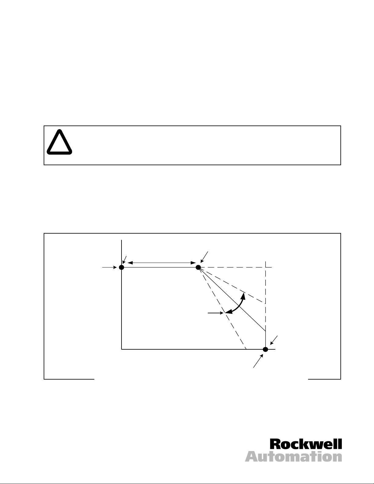
The Torque Taper kit allows fine adjustment of the slope and breakpoint of the drive’s speed-torque curve. It
should be used where simple, center-driven winders and similar applications require a reciprocal speed-torque
relationship to maintain constant tension as material builds up. In these cases, a higher current limit (higher
torque) setting is required for a decrease in motor speed due to a growing diameter. See figure 1.
equipment. Read and understand this manual and other applicable manuals in their entirety
before proceeding. Failure to observe this precaution could result in severe bodily injury or loss
of life.
100%
base
speed
N
(rpm)
The Torque Taper kit comprises a module (printed circuit board) and a mounting screw. No other equipment is
required. However, the Speed potentiometer and either the Torque potentiometer or the Current Limit
potentiometer on the drive’s Regulator module are used in conjunction with the two potentiometers on the
Torque Taper module.
SPEED pot
0
I (torque)
Figure 1 – Torque Curves
CORE TORQUE pot
Torque
taper
100% current (torque)
Current
Limit pot
or
Torque pot
Reliance and MinPak are trademarks of Rockwell Automation.
© 1999 Rockwell International Corporation
Page 2

Installing and Adjusting the Torque Taper Kit
ATTENTION: Do not install modification kits with power applied to the drive. Disconnect, lock
out, and tag all sources of incoming AC power to the drive before attempting such installation.
!
Refer to your drive instruction manual for help locating and identifying drive components.
To install the Torque Taper kit in your non-regenerative FlexPak Plus or MinPak Plus DC drive:
Step 1. Disconnect, lock out, and tag input power to the drive.
Step 2. Remove the drive cover and verify that no voltage is present at the drive’s AC input terminals, L1/181
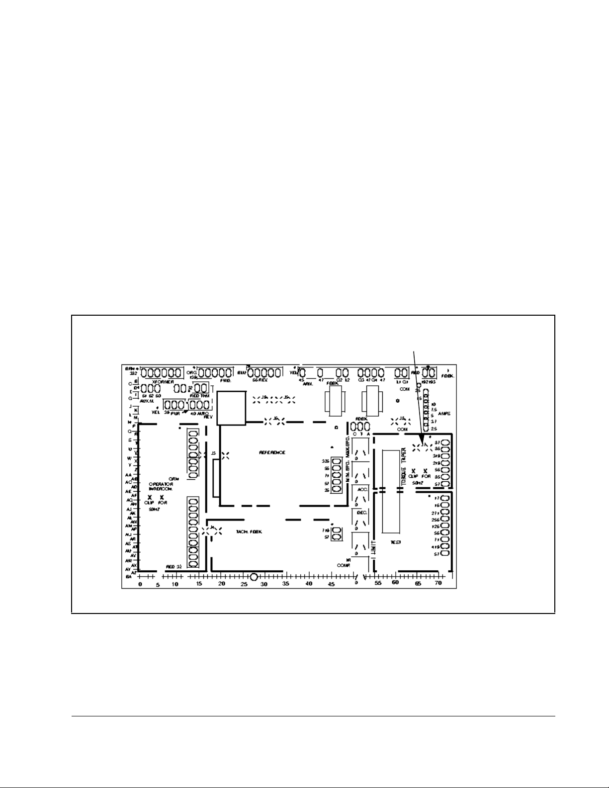
Step 3. Remove jumpers J7 and J8 on the Regulator module. Se e figure 2.
Step 4. Orient the Torque Taper module over the area marked TORQUE TAPER on the Regulator module,
V erify that no voltage is present at the drive’s AC input terminals, L1/181 and L2/182. Failure to
observe this precaution could result in severe bodily injury or loss of life.
ATTENTION: The user is responsible for conforming with all applicable local, national, and
international codes. Failure to observe this precaution could result in damage to, or destruction
of, the equipment.
and L2/182.
just over the seven pins. Press down so that the pins pass through the guides on the Torque Taper
module. Use the mounting screw to secure it.
Step 5. On the Regulator module, adjust the Current Limit potentiometer counter-clockwise (CCW) to 100%,
or lower, depending on the application. It is shipped from the factory set at 150%. Dot No. 4 is
approximately 100%. Refer to figure 3.
Step 6. On the Torque Taper module, turn the CORE TORQUE potentiometer completely CCW. The core
torque setting provides a minimum winding torque, or mimimum strip tension, when the winding cycle
begins.
Step 7. On the Torque Taper module, turn the TORQUE TAP. ADJ. potentiometer completely CW. This
assures that excessive tension will not develop as the first coil or package is wound.
Important: The remaining steps assume that the complete drive system has been successfully started up
according to the instructions in the drive user manual. They provide a power-on test.
Note that an ammeter in the armature circuit is useful when adjusting both potentiometers on the
Torque T aper module. Abserving the ammeter, which shows current, and the growing coil diameter
gives visual confirmation whether the current (Torque) is increasing too fast or slow in relation to
the build-up.
Step 8. Thread the strip onto the winder and securely fasten it to the core. Remove all strip slack before the
drive is restarted.
Step 9. Set the Maximum Speed potentiometer for a safe maximum winder speed.
Step 10. Remove the lockout and tag. Apply power to the drive.
Step 11. Start the drive.
If the strip web breaks immediately, stop the drive. Reduce the Current Limit potentiometer (CCW
reduces current (torque).
2
Torque Taper Kit for Non-Regenerative FlexPak Plus and MinPak Plus DC Drives
Page 3
If the strip does not break immediately, start the process and allow the winder to begin winding.
Accelerate to the normal running speed. On the Torque Taper module, adjust the CORE TORQUE
potentiometer to obtain the desired strip tension at the beginning of the coil (CCW decreases
tension).
Step 12. As the coil or package increases in diameter, adjust the TORQUE TAP. ADJ. potentiometer to
maintain the proper tension (CCW increases tension). Adjust in small increments as the diameter
grows.
Important: Depending on the amount of torque taper desired and the size of the coil or package being wound,
the drive may go into current limit. However, the Current Limit potentiometer on the Regulator
module must never be set higher than 100% of the nameplate current rating on the motor.
Step 13. Stop the drive. Disconnect, lock out, and tag input power to the drive.
Step 14. Reattach the cover to the drive.
Step 15. Remove the lock out and tag.
This completes the installation of the Torque Taper kit.
Remove J7 and J8 if you are
using the Torque Taper kit.
Figure 2 – Regulator Module Jumper Locations
Torque Taper Kit for Non-Regenerative FlexPak Plus and MinPak Plus DC Drives
3
Page 4

Maximum Speed
Minimum Speed
Accel Speed
Decel Speed
Current Limit
IR Comp
Figure 3 – Regulator Module Potentiometers
Publication D2-3386 July 1999 1999 Rockwell International Corporation. All rights reserved. Printed in USA.
Page 5

Page 6

U.S. Drives Technical Support
Tel: (1) 262.512.8176, Fax: (1) 262.512.2222, Email: support@drives.ra.rockwell.com, Online: www.ab.com/support/abdrives
Publication D2-3386– July 1999 Copyright © 1999 Rockwell Automation, Inc. All Rights Reserved.
 Loading...