

Page 1
Dynamic Braking Kit
for FlexP ak Plus and MinP ak Plus DC Drives
Model Numbers 14C214, 14C215, 14C216
Instruction Manual D2-3378
ATTENTION:Only qualified electrical personnel familiar with the construction and operation of
this equipment and the hazards involved should install, adjust, operate, and/or service this
!
Product Description
Installation of the Dynamic Braking kit enables a single-phase FlexPak™ Plus or MinPak™ Plus DC drive to
provide rapid, smooth stopping of the motor. If the Dynamic Braking kit is not used, the drive causes the motor
to coast to rest when the contactor opens.
The Dynamic Braking kit includes a resistor that is automatically switched across the motor’s armature when
the drive is stopped. The rotating mechanical energy of the motor is converted into electrical energy that is
rapidly dissipated as heat. The resistor is sized for infrequent stops, so time must be allowed between stops for
the heat to dissipate.
equipment. Read and understand this manual and other applicable manuals in their entirety
before proceeding. Failure to observe this precaution could result in severe bodily injury or loss
of life.
Important: The dynamic brake is not a mechanical holding brake. It will not hold the motor shaft in place. It will
not prevent the motor from turning once motion has stopped.
The Dynamic Braking kit must be rated for the drive’s horsepower and voltage rating, as shown in table 1. Refer
to your drive’s nameplate for the horsepower and voltage rating. The Dynamic Braking kit contents are also
listed in table 1.
Table 1 – Contents of the Dynamic Braking Kit
Description Quantity Kit Model Number and Rating Reliance Part Number
Dynamic Braking Resistor 1 14C214
1/4 to 1/2 HP @ 115 VAC
2 to 3 HP @ 230 VAC
1 14C215
3/4 HP @ 115 VAC
1 14C216
1/2 to 1-1/2 HP and 5 HP @ 230 VAC
Mounting Screw, 4-40 x 3/8 2 All 601741-74C
Instruction Manual 1 All D2-3378
63481-150QHC
63481-150QCC
63481-150QNC
Reliance and MinPak are trademarks of Rockwell Automation.
© 1998 Rockwell International Corporation
Page 2

Installing the Dynamic Braking Kit in a FlexPak Plus DC Drive
ATTENTION:
out, and tag all sources of incoming AC power to the drive before attempting such installation.
!
Important:
Refer to your FlexPak Plus DC drive instruction manual for help locating and identifying drive components.
Step 1. Disconnect, lock out, and tag input power to the drive.
Step 2. Remove the drive cover.
Step 3. Verify that no voltage is present at the drive’s AC input terminals, L1 and L2.
Step 4. Mount the dynamic braking resistor in the upper right corner on the back of the FlexPak Plus auxiliary
Step 5.
V erify that no voltage is present at the drive’s AC input terminals, L1 and L2. Failure to observe
this precaution could resu lt in severe bodily injury or loss of life.
ATTENTION:
international codes. Failure to observe this precaution could result in damage to, or destruction
of, the equipment.
Dynamic Braking kit installation procedures are different for FlexPak Plus drives and MinPak Plus
DC drives. This section describes installation in a FlexPak Plus drive. See the next section for
installation in a MinPak Plus drive.
panel. Use the two mounting screws provided.
For all regenerative FlexPak Plus DC drives, and for non-r egenerative FlexPak Plus DC drives
without a Reversing Cont actor:
(NC) contacts of the drive’s M-contactor (terminals 7 and 8). This places the resistor across the
motor’s armature (A1 and A2) when the M-contactor is de-energized. Refer to figures 1 and 2.
Do not install modification kits with power applied to the drive. Disconnect, lock
The user is responsible for conforming with all applicable local, national, and
Connect the dynamic braking resistor between the normally closed
2
Dynamic Braking Kit for FlexPak Plus and MinPak Plus DC Drives
Page 3
Dynamic Braking Resistor
M-Contactor or
8
6
7
5
Forward Contactor
4
A1
Figure 1 – Dynamic Braking Resistor Connections for Regenerative FlexPak Plus Drives
and Non-Regenerative FlexPak Plus Drives Without a Reversing Contactor
3
A2
Dynamic Braking Kit for FlexPak Plus and MinPak Plus DC Drives
3
Page 4

47
Forward
Contactor
A1 (+)
Forward
Contactor
DB 1
DC
Motor
Armature
45/52
Dynamic Braking
Resistor
DB 2
Forward
Contactor
Forward
Contactor
Figure 2 – Dynamic Braking Resistor Schematic for Regenerative Drives
and Non-Regenerative Drives Without a Reversing Contactor
A2 (–)
Step 6. For non-regenerative FlexPak Plus DC drives with a Rever sing Cont actor : Connect the dynamic
braking resistor between the corresponding normally closed (
) contacts on the forward contactor
NC
and the reversing contactor. For example, connect the resistor between terminal 8 on the forward
contactor and terminal 8 on the reverse contactor. This places the resistor across the motor’s
armature (A1 and A2) when both contactors are de-energized. Refer to figures 3 and 4.
4
Dynamic Braking Kit for FlexPak Plus and MinPak Plus DC Drives
Page 5

J
'\QDPLF %UDNLQ
J
5HVLVWRU
-XPSHU
0&RQWDFWRU RU
-XPSHU
5HYHUVLQ
&RQWDFWRU
)RUZDUG &RQWDFWRU
-XPSHU $
-XPSHU $
$
$
7R 0RWRU $UPDWXUH
Figure 3 – Dynamic Braking Resistor Connections for Non-Regenerative FlexPak Plus Drives With a Reversing Contactor
Dynamic Braking Kit for FlexPak Plus and MinPak Plus DC Drives
5
Page 6

5HYHUVLQJ
&RQWDFWRU
5HYHUVLQJ
&RQWDFWRU
)RUZDUG
&RQWDFWRU
$
'%
'%
)RUZDUG
&RQWDFWRU
'\QDPLF
%UDNLQJ
5HVLVWRU
5HYHUVLQJ
&RQWDFWRU
'& 0RWRU
$UPDWXUH
)RUZDUG
&RQWDFWRU
Figure 4 – Dynamic Braking Resistor Schematic for Non-Regenerative Drives with a Reversing Contactor
$
ATTENTION:If a reversing contactor is installed, ensure jumper J9 is removed from the
Regulator board (near the top of board). Failure to observe this precaution could result in
!
damage to, or destruction of, the equipment.
Step 7. If a reversing contactor is installed, make sure jumper J9 is removed from the Regulator board (near
the top of board). See the FlexPak Plus DC drive instruction manual for jumper location.
Step 8. Verify the wiring of the Dynamic Braking resistor and that all connectors are securely fastened.
Step 9. Reattach the cover to the drive.
Step 10. Apply power and test the braking capability of the drive.
This completes installation of the Dynamic Braking kit for FlexPak Plus DC drives.
6
Dynamic Braking Kit for FlexPak Plus and MinPak Plus DC Drives
Page 7

Installing the Dynamic Braking Kit in a MinPak Plus DC Drive
ATTENTION:
out, and tag all sources of incoming AC power to the drive before attempting such installation.
!
Important:
Refer to your MinPak Plus DC drive instruction manual for help locating and identifying drive components.
Unless otherwise noted, the following steps must be performed on all MinPak Plus drives.
Step 1. Disconnect, lock out, and tag input power to the drive.
Step 2. Remove the drive cover.
Step 3. Verify that no voltage is present at the drive’s
Step 4. Remove the two screws from the terminal block and circuit breaker mounting bracket. Position this
Step 5.
Verify that no voltage is present at the drive’s
to observe this precaution could result in severe bodily injury or loss of life.
ATTENTION:
international codes. Failure to observe this precaution could result in damage to, or destruction
of, the equipment.
Dynamic Braking kit installation is different for FlexPak Plus and MinPak Plus DC drives. This
section describes how to install the Dynamic Braking kit in a MinPak Plus DC drive. Refer to the
previous section for installation in a FlexPak Plus DC drive.
bracket up and out of the way as far as possible.
Regenerative MinPak Plus only
them aside.
Do not install modification kits with power applied to the drive. Disconnect, lock
input terminals, L1/181 and L2/182. Failure
AC
The user is responsible for conforming with all applicable local, national, and
input terminals, L1/181 and L2/182.
AC
: Loosen the auxiliary mounting bracket and the M-contactor. Move
Step 6. Locate the two small drilled holes near the upper right of the chassis.
Step 7. Position the Dynamic Braking kit so that the longer lead is toward the right side of the chassis. Mount
it with the two mounting screws provided.
Step 8.
Step 9.
Step 10. Verify the wiring of the Dynamic Braking resistor. Make sure connectors are securely fastened.
Step 11. Reattach the terminal barrier and circuit breaker mounting bracket removed in step 4.
Step 12. Reattach the cover to the drive.
Step 13. Apply power and test the braking capability of the drive.
This completes the installation of the Dynamic Braking Kit for the MinPak Plus DC drives.
For all regenerative MinPak Plus DC drives and non-regenerative MinPak Plus DC drives
without a Reversing Contactor:
contacts of the drive’s M-contactor. These contacts are to the rear of the M-contactor. This places the
resistor across the motor’s armature when the M-contactor is de-energized. Refer to figures 2 and 5.
For non-regenerative MinPak Plus DC drives with a Reversing Contactor:
braking resistor between corresponding normally closed (
the reversing contactor. These contacts are to the rear of the contactors. This places the resistor
across the motor armature (A1 and A2) when the contactors are de-energized. Refer to figures 4
and 6.
Connect the dynamic braking resistor to the normally closed (
Connect the dynamic
) contacts on the forward contactor and
NC
NC
)
Dynamic Braking Kit for FlexPak Plus and MinPak Plus DC Drives
7
Page 8

.
'\QDPLF %UDNLQJ 5HVLVWRU
0&RQWDFWRU
$
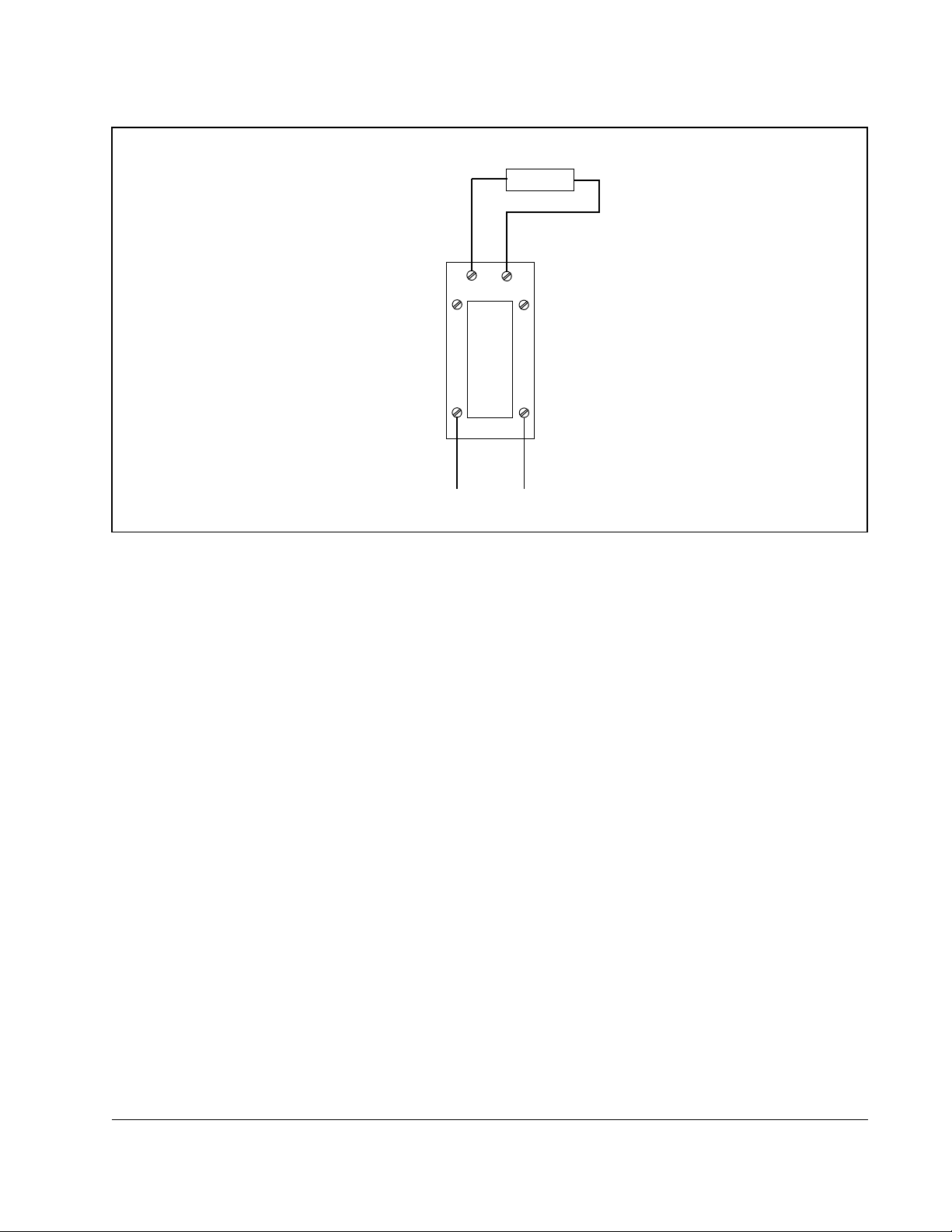
Figure 5 – Dynamic Braking Resistor Connections for MinPak Plus Drives Without a Reversing Contactor
'\QDPLF %UDNLQJ 5HVLVWRU
0&RQWDFWRU
$
$
$
5HYHUVLQJ
&RQWDFWRU
$
$
Figure 6 – Dynamic Braking Resistor Connections for MinPak Plus Drives With a Reversing Contactor
Publication D2-3378 November 1998 1998 Rockwell International Corporation. All rights reserved. Printed in USA.
Page 9

Page 10

U.S. Drives Technical Support
Tel: (1) 262.512.8176, Fax: (1) 262.512.2222, Email: support@drives.ra.rockwell.com, Online: www.ab.com/support/abdrives
Publication D2-3378– November 1998 Copyright © 1998 Rockwell Automation, Inc. All Rights Reserved.
 Loading...