

Page 1
1
Einbauanleitung
(c) Installation Instructions
Notice d'installation
Deutch /
Français
(b) Description
The single and dual key slamlock units allow an actuator which would
normally be fixed to an access gate/door, to be trapped in the
interlock until released by the insertion and rotation of a key(s).
Dual key versions are either two keys in to release the actuator or
one key in and one key released with the actuator as a personnel
key for full body access applications.
Beschreibung
Mit den Slamlock-Einheiten kann ein Betätiger, der normalerweise
an einer Zugangstür montiert wird, in der Verriegelung solange
arretiert werden, bis ein (zwei) Schlüssel eingesteckt und gedreht
werden. Versionen sind als zwei Schlüssel eingesteckt zum
Entriegeln des Betätigers erhältlich bzw. als ein Schlüssel
eingesteckt und ein Schlüssel herausgezogen, wobei der Betätiger
als persönlicher Schlüssel für kompletten Zugang benutzt wird.
Description
Dans ce dispositif de verrouillage réciproque, le pêne fixé sur une
porte d'accès est libéré par l'insertion et la rotation de la clé. Des
versions à deux clés sont disponibles, une exigeant l'introduction et
la rotation des deux clés et l'autre l'introduction d'une des clés pour
libérer le pêne et l'autre clé permettant ainsi l'accès du personnel.
RETAIN THESE INSTRUCTIONS
Installation must be in accordance with the following steps and must be
carried out by suitably competent personnel.
This device is intended to be part of the safety related control system. Before
installation, a risk assessment should be performed to determine whether the
specifications of this device are suitable for all foreseeable operational and
environmental characteristics of the machine to which it is to be fitted.
At regular intervals during the life of the unit check whether these
characteristics foreseen remain valid and inspect this device for evidence of
accelerated wear, material degradation or tampering. If necessary the device
should be replaced . The manufacturer cannot accept responsibility for a
failure of this device if the procedures given in this sheet are not implemented
or if it is used outside the recommended specifications in this sheet.
Adherence to the recommended maintenance instructions forms part of the
warranty.
DIESE ANLEITUNG AUFBEWAHREN
Die Installation muß unter Einhaltung der nachstehend beschriebenen
Schritte, und durch geeignetes, fachlich qualifiertes Personal erfolgen.
Diese Vorrichtung ist als Teil des sicherheitsrelevanten Kontrollsystems
beabsichtigt. Vor der Installation sollte eine Risikobewertung zur Festlegung
dessen erfolgen, ob die Spezifikationen dieser Vorrichtung für alle
vorhersehbaren betrieblichen und umweltbezogenen Eigenschaften der
Maschine geeignet sind, an der sie installiert werden soll.
Zu regelmäßigen Abständen während der Lebensdauer der Baugruppe ist zu
überprüfen, ob die vorgesehenen Eigenschaften weiterhin gültig sind, und
ob Anzeichen von vorzeitigem Verschleiß, Materialermüdung oder
unbefugten Eingriffen erkennbar sind. Falls erforderlich, sollte die
Vorrichtung ausgetauscht werden. Der Hersteller kann keinerlei
Verantwortung für ein Versagen dieser Vorrichtung übernehmen, wenn die in
diesem Datenblatt gegebenen Verfahrensweisen nicht implementiert
wurden, oder wenn sie außerhalb der auf diesem Schriftblatt empfohlenen
Spezifikationen verwendet wird.
Die Einhaltung der empfohlenen Wartungsvorschriften formt Teil der
Garantie.
CONSERVEZ CES INSTRUCTIONS
L’installation doit être effectuée par du personnel qualifié qui respectera les
étapes suivantes.
Ce système est conçu pour être implanté dans la partie sécurité du système
de commande. Avant l’installation, il faut effectuer une appréciation des
risques pour vérifier que les caractéristiques de cet appareil sont appropriées
aux critères d’utilisation et d’environnement de la machine.
Pendant toute la vie de la machine, en respectant des périodes de vérification
régulières, assurez-vous que l’appareil conserve ses performances, inspectez
le montage du dispositif pour déceler des traces éventuelles d’usure, de
dégradation ou de fraudes. Si nécessaire, remplacez l’appareil. Le fabricant
n'accepte pas la responsabilité pour des pannes éventuelles de cet appareil si
les procédures décrites dans la présente notice n’ont pas été respectées ou si
l’appareil est utilisé en dehors des recommandations dans la présente.
Le respect des instructions relatives à l’entretien recommandé font partie
intégrante de la garantie.
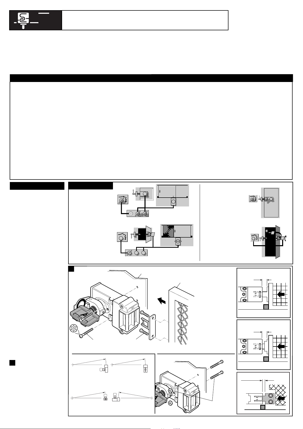
(a) SINGLE AND DUAL KEY SLAMLOCK
SLAMLOCK-EINHEITEN MIT EINEM ODER ZWEI SCHLÜSSELN
DISPOSITIF DE VERROUILLAGE RECIPROQUE A ENCLENCHEMENT A UNE OU DEUX CLES
PROSAFE
INTERLOCKING
& CONTROL SOLUTIONS
ACCESS KEYS TRAPPED.
KEY TRAPPED
ELECTRICAL
SUPPLY ON
B
Machine is running - Electrical supply is
ON - All access doors are locked.
ELECTRICAL
SUPPLY
LOCKED OFF
ACCESS KEYS FREE.
ELECTRICAL ISOLATION KEY TRAPPED.
A
A
BB
B
Machine is now stopped - Electrical supply
is isolated - Access doors can now be opened
- When Doors are open, keys are trapped.
A
Machine is now stopped Electrical supply is isolated Door can now be opened With door open Key A is trapped Key B is taken into guarded area to
ensure the door cannot be locked by
a third party.
B
A
A
A
KEY TRAPPED
ELECTRICAL
SUPPLY ON
Machine running
- Electrical supply
ON - Access door
Locked.
B
(a) FIXED GUARD
PART BODY ACCESS FULL BODY ACCESS(d)
(e)
(f)
(h)
(g)
(i)
(j)
ELECTRICAL
SUPPLY
LOCKED OFF
(h)
(e)
(m)
(l)
(k)
(c)
APPLICATION EXAMPLES
1
(a) FESTGESCHRAUBTE SCHUTZTÜR /
PROTECTION FIXE
(b) SCHUTZTÜR /
PORTE D'ACCES
(c) Version ein Schlüssel /
Version à clé simple
(d) Version zwei Schlüssel /
Version à deux clés
(e) Betätigerführung
/
Guide d’émetteur
(f) Flexibler Betätiger
/
Emetteur flexible
(g) Flacher Betätiger /
Emetteur plat
(h)
Schutztür-Arretierungen
/
Butée de porte
(i) MONTAGE VORNE /
MONTAGE SUR L’AVANT
(j) MONTAGE HINTEN /
MONTAGE SUR L’ARRIERE
(c) ANWENDUNGSBEISPIELE /
Exemples
d’application
(d) TEILWEISER KÖRPERLICHER ZUGANG /
ACCES AU CORPS DE LA PIECE
(e) SCHLÜSSEL ARRETIERT, STROMVERSORGUNG EIN /
CLÉ VERROUILLÉE - MACHINE SOUS TENSION
(f) ZUGANGSSCHLÜSSEL ARRETIERT /
CLÉS D’ACCES VERROUILLÉES
(g) Maschine läuft - Stromversorgung EIN -
Alle Zugangstüren sind verriegelt /
La machine
est en marche - La machine est sous tension Toutes les portes d’accès sont verrouillées
(h) STROMVERSORGUNG DURCH SCHLÜSSEL
GESPERRT /
ALIMENTATION ELECTRIQUE
BLOQUEE HORS CIRCUIT
(i) ZUGANGSSCHLÜSSEL FREI-SCHLÜSSEL FÜR
ELEKTRISCHE TRENNUNG ARRETIERT /
CLÉS
D’ACCES LIBRES - CLÉ DE COUPURE DE
L’ALIMENTATION ELECTRIQUE VERROUILLÉE
(j) Maschine steht jetzt still - Die Stromversorgung ist
getrennt - Zugangstüren können jetzt geöffnet
werden - Bei geöffneter Tür werden die
Schlüssel arretiert. /
La machine est maintenant
arrêtée - L’alimentation électrique est coupée - On
peut ouvrir les portes d’accès - Lorsque les portes
sont ouvertes, les clés sont verrouillées
(k) VOLLER KÖRPERLICHER ZUGANG /
ACCES INTEGRAL AU CORPS
(l) Maschine läuft - Stromversorgung EIN -
Zugangstür verschlossen. /
La machine est en
marche - La machine est sous tension - Toutes les
portes d’accès sont verrouillées
(m) Maschine steht jetz still - Die Stromversorgung ist
getrennt - Die Tür kann jetzt geöffnet werden Bei geöffneter Tür wird Schlüssel A arretiert
- Schlüssel B wird in einem bewachten
Bereich aufbewahrt, um sicherzustellen, daß
die Tür nicht durch eine dritte Person
verschlossen werden kann. /
La machine est
maintenant arrêtée - L’alimentation électrique est
coupée - On peut ouvrir la porte - Lorsque la porte
est ouverte, la clé A est bloquée - La clé B est
placée dans une zone surveillée afin d’assurer que
la porte ne puisse pas être verrouillée par des tiers
(b) GUARD DOOR
M5 (x2 - (c) Single Key version)
(x4 -
(d) Double Key version)
2 x M5
(j) REAR MOUNTING
(i) FRONT MOUNTING
1mm min
2.5mm max
1mm min
2.5mm max
(h) GUARD STOP
(b) GUARD DOOR
7mm min
9.5mm max
(h) GUARD STOP
(b) GUARD DOOR
FLEXIBLE ACTUATOR
STANDARD ACTUATOR
(f)
(e)
(h) GUARD STOP
(b) GUARD DOOR
FLAT ACTUATOR(g)
ACTUATOR MIN.RADIUS
A
A
A
ACTUATOR MIN.RADIUS
ACTUATOR MIN.RADIUS
ACTUATOR MIN.RADIUS
STD. ACTUATOR 175mm
FLEX. ACTUATOR 60mm
FLAT ACTUATOR 175mm
(e)
(f)
(g)
STD. ACTUATOR 175mm
FLEX. ACTUATOR 60mm
FLAT ACTUATOR 175mm
(e)
(f)
(g)
STD. ACTUATOR 175mm
FLEX. ACTUATOR 60mm
FLAT ACTUATOR 175mm
(e)
(f)
(g)
STD. ACTUATOR 175mm
FLEX. ACTUATOR 60mm
FLAT ACTUATOR 175mm
(e)
(f)
(g)
M5 (x2 - (c) Single Key version)
(x4 -
(d) Double Key version)
Page 2

3
(a) OPERATION / BEDIENUNG / UTILISATION
ADJUSTING POSITION OF FLIP CAP IF REQUIRED
Loosen grub screw in cap
Rotate cap and tighten grubscrew
2
(c)
(b)
(a)
Deutch /
Français
(a) Falls erforderlich, Position der
Schutzklappe justieren /
Ajustez la
position du chapeau basculant, si nécessaire
(b) Gewindestift in der Klappe lösen /
Desserrez la vis sans tête dans le chapeau
(c) Klappe rotieren, und Gewindestift
festziehen /
Tournez le chapeau et serrez
la vis sans tête
2
3
(b) Single Key
(f) Key C trapped, Key D free, actuator free. (g) Key C free, Key D trapped. actuator trapped.
(i) Key C and D trapped, actuator free. (j) Key C and D free, actuator trapped.
(b) Ein Schlüssel /
Clé simple
(c) Schlüssel arretiert, Betätiger frei /
Clé prisonnière, pêne libéré
(d) Schlüssel frei, Betätiger arretiert /
Clé retirée, pêne prisonnier
(e) Zwei Schlüssel (einer arretiert, einer frei)
/
Deux clés (une insérée, une libre)
(f) Schlüssel C arretiert, Schlüssel D frei,
Betätiger frei /
Clé C prisonnière, clé D
retirée, pêne libéré
(g) Schlüssel C frei, Schlüssel D arretiert,
Betätiger arretiert /
Clé C retirée, clé D
prisonnière, pêne prisonnier
(h) Zwei Schlüssel (beide arretiert) /
Deux
clés (deux insérées)
(i) Schlüssel C und D arretiert, Betätiger frei
/
Clés C et D prisonnières, pêne libéré
(j) Schlüssel C und D frei, Betätiger arretiert
/
Clés C et D retirées, pêne prisonnier
(k) Erster /
Primaire
(l) Zweiter /
Secondaire
(e) Dual Key (one in, one out)
(h) Dual Key (two in)
(d) Key free, actuator trapped.(c) Key trapped, actuator free.
90°
90°
90°
(k) PRIMARY
(l) SECONDARY
PRIMARY
SECONDARY
90°
90°
UNITS SHOULD BE
INSTALLED WITH FLIP CAP
HINGE UPPERMOST
Page 3

Deutsch /
Français
Technical Specifications
Conforming to standard Relevent clauses of EN 292 & EN 1088
Maximum operating temperature -40°C to +200°C
Mechanical operations In excess of 10
5
operations under
normal working conditions.
Max. shear force to key 15.1 kN
Max. torque to key 14 Nm
Relative operating humidity 25% to 95%
Weight (single key version) 760gm
(dual key version) 1332gm
Code barrels Fire tested to a temperature in excess
of 760°C for a period of one half hour.
Ambient working temperature -10°C to +50°C
Material 316L Stainless Steel
Assembly fixings Anti-tamper screws
Mounting holes (switch) 2 (4) x M5 c'bored from the top face
2 (4) x M5 from underside with M5 nuts
(actuator) 2 x M5
It is strongly recommend that
anti-tamper screws are used.
Max. holding force 2000N
(n)
(a)
DIMENSIONS / ABMESSUNGEN / DIMENSIONS
(b) M5 MITTIG VON OBEN BOHREN. M5 VON
UNTERSEITE MIT M5 SCHRAUBEN
BEFESTIGEN /
M5 CHAMBRE A PARTIR DU
HAUT FIXATION M5 DU DESSOUS AVEC
BOULONS M5
(c) OBERER EINGANG /
OUVERTURE SUPERIEURE
(d) VORDERER EINGANG /
OUVERTURE
FRONTALE
(e) UNTERER EINGANG /
OUVERTURE
INFERIEURE
(f) SLAMLOCK EIN SCHLÜSSEL /
DISPOSITIF A
UNE CLE
(g) SLAMLOCK ZWEI SCHLÜSSEL /
DISPOSITIF
A DEUX CLES
(h) Betätigerführung
/
Guide d’émetteur
(i) Flexibler Betätiger
/
Emetteur flexible
(j) Flacher Betätiger /
Emetteur plat
(k) Schrauben für den codierten Zylinder
M4 x 10 Torx Kopf
Beschichtet mit einem Sicherungslack /
Vis avec tete TORX, bloque avec un vernis.
(g) DOUBLE KEY SLAMLOCK
Technische Daten
Erfüllt die Normen Anwendbare Abschnitte von EN 292 und
EN 1088
Max. Betriebstemperatur -40°C bis +200°C
Mechanische Lebensdauer 1 x 10
5
Mechanische Lebensdauer Betriebsbedingungen 0,1kg
Max. Scherkraft auf Schlüssel 15.1 kN
Max. Drehmoment auf Schlüssel 14 Nm
Relative Feuchte 25% bis 95%
Gewicht (ein Schlüssel) 760gm
(zwei Schlüssel) 1332gm
Schloßzylinder Brandtest 760°C, 30min.
Umgebungstemperatur -10°C bis +50°C
Material 316L Stainless Steel
Montageschrauben Eingriffssichere Schrauben
Montagelöcher (Schalter) 2 (4) x M5-Schrauben von oben, 2 (4)
x M5 Gewinde, 5mm tief von unten.
(Betätiger) 2 x M5
Wirempfehlen die Verwendung von
Sicherheitsschrauben (TORX)
Zuhaltekraft max. 2000N
Specifications Techniques
Conformité aux normes EN 292 & EN 1088
Température maximale de service -40 à +200°C
Opérations mécaniques 10
5
opérations dans des conditions
normales d'utilisation.
Force maximale applicable à la clé 15,1 kN
Couple maximale applicable à la clé 14 Nm
Humidité supportée 25% - 95%
Poids (modèle à une clé) 760gm
(modèle à deux clés) 1332gm
Canon du boiter A subi un essai au feu à plus de 760°C
pendant plus de 30 minutes.
Température ambiante d’utilisation -10 à +50°C
Composition Acier inoxydable 316L
Fixations d’assemblage Vis de sécurité Vis des sécurité
Trous de fixation (serrure) 2 (4) x M5 sur le dessus.
2 (4) x M5 x 5 mm de profondeur
depuis le dessous.
(pêne) 2 x M5
Les vis de sécurité sont conseillées.
Résistance maximale 2000N
(f) SINGLE KEY SLAMLOCK
38.3
3.5
48.0
43.6
64.1
20.8
20.8
28.5 & 30
PITCH RANGE
TOP ENTRY
(b)
M5 C'BORED FROM TOP.
M5 FIXING FROM U'SIDE
USING M5 NUTS IN RECESSES
FRONT ENTRY
BOTTOM ENTRY
5.5
34
5
4
93
25.4
SECONDARY PRIMARY
25.4
28.5 & 30
PITCH RANGE
(b) M5 C'BORED FROM TOP.
M5 FIXING FROM U'SIDE
USING M5 NUTS IN
RECESSES
3.5
3.5
43.6
38.3
64.1
57.7
57.7
4
151
BOTTOM ENTRY
FRONT ENTRY
5.5
20.8
5
34
TOP ENTRY
48.0
20.8
52
40
18
4
36
14.5
3.5
M5 CSK
35
67
18
36
4
2 HOLES
Ø5.5 THRO
13
19
51
20
8
524031
18
2 OFF 5.5 SLOTS
(j) STANDARD ACTUATOR
(h) FLAT ACTUATOR
(i) FLEXIBLE/ADJUSTABLE ACTUATOR
(c)
(d)
(e)
(c)
(d)
(e)
(k)
CODE BARREL SCREWS
M4 x 8 TORX HEAD
(k)
CODE BARREL SCREWS
M4 x 8 TORX HEAD
Page 4

Drg No: 7200059 / Issue No: 1
Change no. 7819
REPARATUR
(p) REPAIR RÉPARATION
If there is any malfunction or damage to the unit or key, replace
where necessary. No attempt to repair should be made. The unit or
key should be replaced before the system is reinstated.
This is to declare that the single key and dual key slamlocks conform with the Essential Health & Safety Requirements (EHSR's) of the European Machinery Directive
(98/37/EC) and the relevant requirements of the Low Voltage Directive (73/23/EEC as amended by 93/68 EEC). The single key and dual key slamlocks also
conforms to EN 1088, EN 60947-5-1, EN 292, EN 60204-1 and are pending Third Party Approved by BG.
Signed for EJA Ltd (Prosafe)
S. F. Mitchell
Deputy Managing Director
Declaration of Conformity / Konformitätserklärung / Déclaration de conformité (e)
WARTUNG
(o) MAINTENANCE ENTRETIEN
Every Week
Check for correct operation of the unit. Ensure unit is securely
mounted. Also check for signs of abuse or tampering. Inspect the
unit, key and actuator for damage. Replace if apparent.
At least every 6 months
Inspect the unit and key for damage. Replace if apparent. Clean out
any accumulation of fine dirt etc. Lubricate code barrel assembly with
light oil or spray. Assessment of operating environment may require
unit to be lubricated more frequently. Check for correct operation.
Wöchentlich
Die korrekte Funktion der Einheit prüfen. Sicherstellen, daß die
Einheit betriebssicher montiert ist. Außerdem auf Anzeichen von
Mißhandlung oder unbefugten Eingriffen untersuchen und ggf.
austauschen.
Mind. Alle 6 Monate
Prüfen Sie die Verriegelung und die Schlüssel auf Beschädigungen
und ersetzen Sie die beschädigten Teile. Befreien Sie die Verriegelung
und die Schlüssel von Verschmutzungen. Schmieren Sie den codierten
Zylinder mit harzfreiem Öl. Prüfen Sie ob eine Reinigung und
Schmierung öfter durchgeführt werden muss. Prüfen Sie die Funktion
der Verriegelung.
Toutes les semaines
Vérifier que l’unité fonctionne correctement. Vérifier qu’elle est
correctement fixée. Chercher aussi tout signe d’abus ou d’infraction.
Examiner l’unité et la clé pour détecter tout dégât éventuel.
Remplacer le cas échéant.
Au moins une fois tous les 6 mois
Inspecter l'appareil et la cle pour detecter tout dommage. Remplacer
l'appareil si necessaire. Nettoyer toute accumulation de poussieres
fines etc. Lubrifier le barillet code avec une huile fine ou un Spray.
Apprecier la frequence des operations de lubrification en fonction de
l'environnement dans lequel fonctionne l'appareil. Controler le bon
fonctionnement.
Wenn Sie irgendwelche Manipulationen oder Beschädigungen an der
Verriegelung oder den Schlüsseln feststellen können, tauschen Sie
diese aus. Reparaturen an der Verriegelung sind ausschliesslich vom
Hersteller durchzuführen. Die beschädigte Verriegelung sollte ersetzt
werden, bevor Sie die Anlage wieder in Betrieb nehmen.
Si un mauvais fonctionnement est detecte sur l'appareil ou la cle,
remplacer l'element necessaire. Aucun delai pour reparer n'est
accepte. L'appareil ou la cle doivent etre remplaces avant la remise
en service du systeme.
EJA Ltd. (Prosafe)
Hindley Green Ind. Est. Wigan, England WN2 4HR
Tel: 01942 255166 (Int: +441942 255166)
Fax: 01942 523259 (Int: +44 1942 523259)
Guardmaster Sicherheitstechnik GmbH.
Am Stadion 15, 42897 Remscheid, Deutschland
Telefon: (02191) 9685-0 Telefax: (02191) 9685-20
Guardmaster Sarl
Parc d'entreprises EUROCAP/COURTIMMO
Bâtiment H1, 62231 COQUELLES
Téléphone: 03 21 00 73 74 Télécopie: 03 21 00 12 34
E-mail: directinfo@guardmaster.fr
Site internet: http://www.guardmaster.fr
ISO 9001
FM 21701
 Loading...