

Page 1
Installation Instructions
P
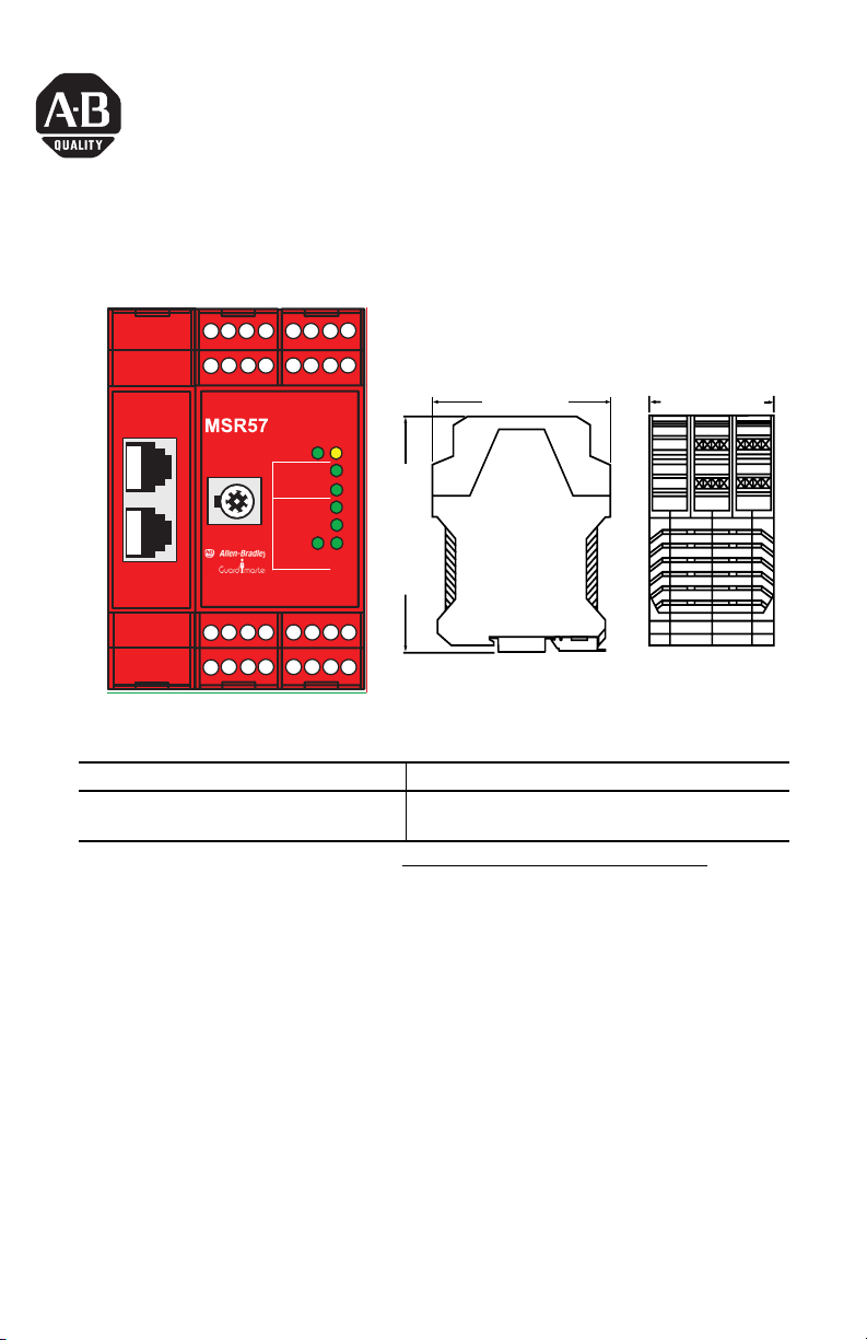
GuardMaster MSR57P Speed Monitoring Safety Relay
Catalog Number 440R-S845AER-NNL
Dimensions
S32 S52 S62S42 13 24 A114
S11 S12 S22S21 34515244
Encoder 1
Encoder 2
DPI
S72 X32X42S82 Y1 S34Y37Y2
Y31Y33 Y30Y3268Y35A278
PWR/Fault
InputsStatus
Limited Speed
Standstill
Safe Speed
Motion Power
Config
Lock
Stop
Door
114.5 mm (4.51 in.)
Additional Resources
Resource Description
GuardMaster MSR57P Speed Monitoring Safety
Relay User Manual, publication 440R-UM004
You can view or download publications at http://literature.rockwellautomation.com. To order
paper copies of technical documentation, contact your local Rockwell Automation distributor
or sales representative.
Detailed information on wiring, configuring, and operating
an MSR57P relay, including safety requirements.
99 mm (3.9 in.)
67.5 mm (2.66 in.)
Publication 440R-IN016B-EN-P - November 2008
Page 2
2 GuardMaster MSR57P Speed Monitoring Safety Relay
Installation Instructions in Other Languages
English This instruction sheet is available in multiple languages at
http://rockwellautomation.com/literature
. Select publication language and type “MSR57P” in
the search field.
Deutsch Dieses Instruktionsblatt kann in mehreren Sprachen unter
http://rockwellautomation.com/literature
gelesen werden. Bitte Ihre Sprache anwählen und
“MSR57P” im Suchfeld eintippen.
Français Ces instructions sont disponibles dans différentes langues à l’adresse suivante:
http://rockwellautomation.com/literature
. Sélectionner la langue puis taper << MSR57P >> dans
le champ de recherche.
Italiano La presente scheda d’istruzione è disponibile in varie lingue sul sito
http://rockwellautomation.com/literature
. Selezionare la lingua desiderata e digitare “MSR57P”
nel campo di ricerca.
Español Puede encontrar esta hoja de instrucciones en varios idiomas en
http://rockwellautomation.com/literature
. Seleccione el idioma de publicación y escriba
“MSR57P” en el campo de búsqueda.
Português Esta folha de instruções está disponível em várias línguas em
http://rockwellautomation.com/literature
. Seleccione a língua de publicação e entre com
“MSR57P” no espaço de busca.
Polish Ta kartka z instrukcjami jest dostepna w wielu jezykach na stronie:
http://rockwellautomation.com/literature
. Wybierz jezyk publikacji i wpisz w polu poszukiwania
“MSR57P”.
Czech Tyto pokyny jsou k dispozici v nekolika jazycích na http://rockwellautomation.com/literature
Zvolte si jazyk publikace a do vyhledávacího polícka vepište “MSR57P”.
Swedish Detta instruktionsblad finns på olika språk på http://rockwellautomation.com/literature
. Välj
önskat språk och skriv “MSR57P” i sökrutan.
Dutch Dit instructieblad is beschikbaar in diverse talen op: http://rockwellautomation.com/literature
Kies taal van publicatie en tik “MSR57P” in het zoekveld.
Chinese
(complex)
從以下網頁可以獲得本說明書的多種語言的版本 :
請選擇出版物的語言 , 並在搜索欄輸入 “MSR57P”。
http://rockwellautomation.com/literature
Chinese
(simplified)
Japanese
从以下网页可以获得本说明书的多种语言的版本 :
请选择出版物的语言 , 并在搜索栏输入 “MSR57P 印
本説明書シートの多言語版は Web サイト
にて入手できます。出版言語を選択し、検索フィールドに 「
http://rockwellautomation.com/literature
http://rockwellautomation.com/literature
ٛ
MSR57P
」とタイプしてください。
.
.
。
。
Publication 440R-IN016B-EN-P - November 2008
Page 3
GuardMaster MSR57P Speed Monitoring Safety Relay 3
General Safety Information
Retain these instructions for future reference. Rockwell Automation cannot accept
responsibility or liability for a failure of this device if the product is used outside the
recommended specifications in this document.
ATTENTION
This device is intended to be part of the safety-related control system of a machine. Before
installation, a risk assessment should be performed to determine whether the specifications
of this device are suitable for all foreseeable operational and environmental characteristics
for the machine to which it is to be fitted. At regular intervals during the life of the machine,
check whether the characteristics foreseen remain valid.
ATTENTION
Safety Programmable Electronic Systems (PES)
Personnel responsible for the installation and application of safety-related programmable
electronic systems (PES) shall be aware of the safety requirements in the application of the
system and shall be trained in using the system.
Spacing Requirements
Adequate air space must be provided around the system (module cluster). Minimum
recommended clearances:
• 15 mm (0.6 in.) above
• 15 mm (0.6 in.) below
• 2…3 mm (0.08…0.12 in.) between modules at ambient temperatures higher
than 40 °C (104 °F).
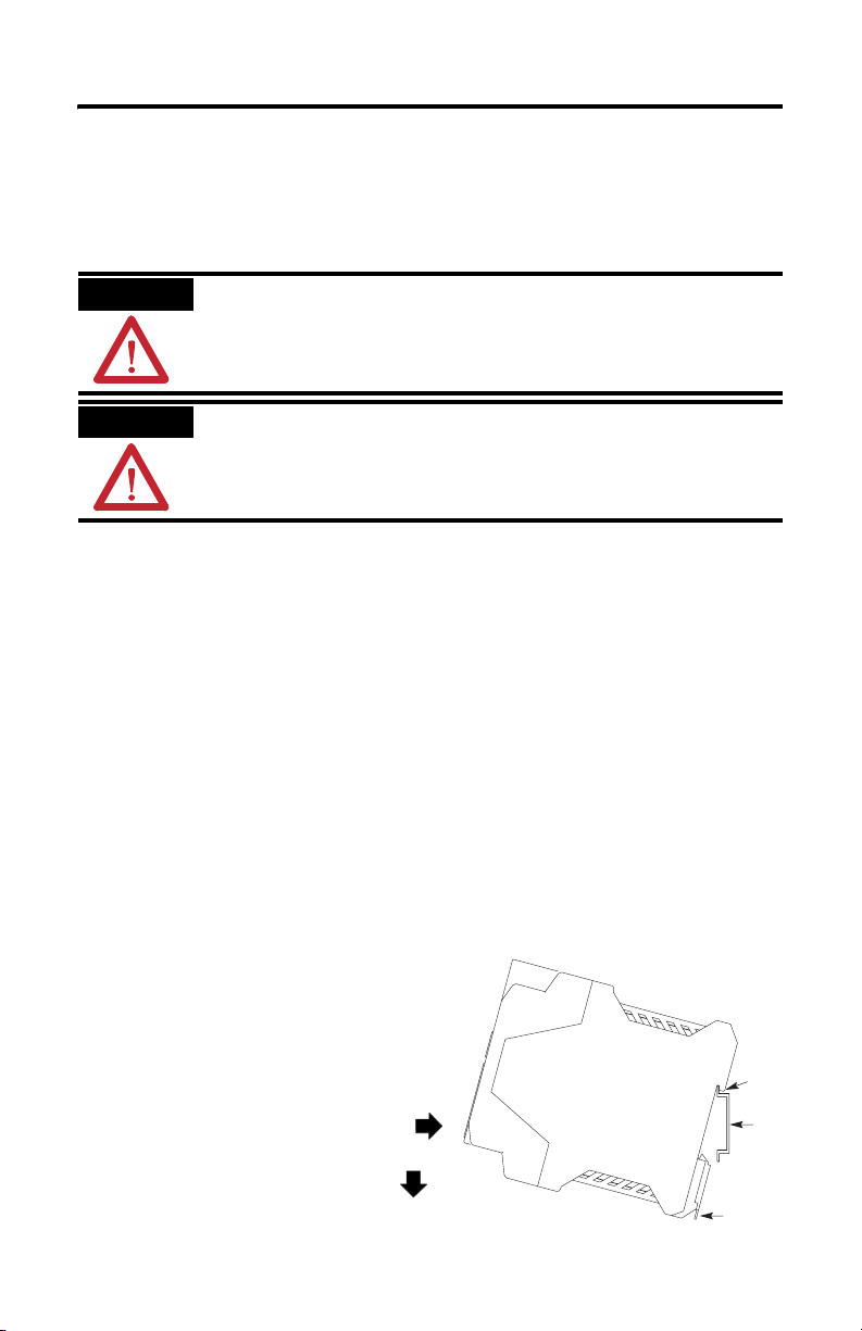
Mount the MSR57P Relay
Follow these steps to mount the MSR57P relay to an EN50022 -35 x 7.5 DIN rail.
1. Hook the top slot over the DIN
rail.
2. Snap the bottom of the device
into position while pressing the
device down against the top of
the rail.
3. Attach end plates on each end
of the DIN rail.
To remove the device from the DIN rail,
use a flathead screwdriver to pull down
the latch and lift the device from the rail.
Latch
Slot
DIN
Rail
Publication 440R-IN016B-EN-P - November 2008
Page 4
4 GuardMaster MSR57P Speed Monitoring Safety Relay
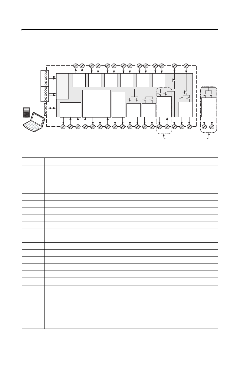
Circuit Diagram
S72
Enabling
Switch
(ESM_In)
Fault_Status
Y37Y35
S82
SS_Out
(Cascade)
2 OSSD
34
S32 S42
Door
Monitor
(DM_In)
44
SLS_Out
(Cascade)
2 OSSD
X32 X42
Lock
Monitor
(LM_In)
7868
Door Lock
Control
(DC_Out)
bipolar
Hi
51 A252
13
A1
Door Lock
Motion
Power
(MP_Out)
Lo
2 OSSD
14
Control
(DC_Out)
Cascade
Hi
Hi
24
51 52
HIM
Encoder 1Encoder 2
RJ45-1
RJ45-2
DPI
Mini-DIN
Monitor
Encoder
PS
24V dc
Y1
S11
Outputs
Reset_In
S34 Y2
Pulse
Tes t
Feedback
S21
(RL_In)
S22
S12
Safe
Stop
(SS_In)
Isolated Outputs
24V dc
Stop_Command
Y32 Y33
Y31
SLS_Command
S52 S62
Safe
Limited
Speed
(SLS_In)
GND
Y30
Diag.
Out
SLS_Status
Terminal Connections
Terminal Function
A1 +24V dc, user supply
A2 Common, user supply
S11, S21 Test_Out_0, Test_Out_1, pulse test outputs for safety functions
S12, S22 SS_In_Ch0, SS_In_Ch1, Safe Stop (SS) dual-channel input
S72, S82 ESM_In_Ch0, ESM_In_Ch1, Enabling Switch Monitor (ESM) dual-channel input
S52, S62 SLS_In_Ch0, SLS_In_Ch1, Safe Limited Speed (SLS) dual-channel input
S32, S42 DM_In_Ch0, DM_In_Ch1, Door Monitor (DM) dual-channel input
X32, X42 LM_In_Ch0, LM_In_Ch1, Lock Monitor (LM) dual-channel input, solenoid position
Y1 24V dc output for reset (S34) and for feedback (Y2)
S34 Reset_In
Y2 RL_In, feedback input
Y35 SLS_Status output
Y37 Fault_Status output
13 Supply power for Motion Power (MP) safety outputs 14 and 24
14, 24 MP_Out_Ch0, MP_Out_Ch1, Motion Power (MP) outputs
68, 78 SLS_Out_Ch0, SLS_Out_Ch1, Safe Limited Speed (SLS) outputs
51
52
DC_Out_Ch0 (High Side), Door Control output [door switch solenoid, bipolar or cascading
DC_Out_Ch1 (Low Side), Door Control output [door switch solenoid, bipolar or cascading
34, 44 SS_Out_Ch0, SS_Out_Ch1, cascading Safe Stop outputs
Y31 24V dc power for isolated outputs
Y32 Stop_Command, isolated output
Y33 SLS_Command, isolated output
Y30 GND for isolated outputs
(1) The DC_Out output may also be configured as cascading (2 Channel Source). For information on using this configuration in
limited applications, refer to the GuardMaster Speed Monitoring Safety Relay User Manual, publication 440R-UM004.
(1)
]
(1)
]
Publication 440R-IN016B-EN-P - November 2008
Page 5

GuardMaster MSR57P Speed Monitoring Safety Relay 5
Status Indicators
Indicator Status Description
(1)
PWR/Fault
Config Lock
Stop Green/On The Safe Stop (SS) input is closed.
Limited
Speed
Motion Power Green/On The Motion Power (MP) output is ON.
Door Green/On The door is closed.
Safe Speed Green/On Safe Limited Speed is being actively monitored and is below the
Standstill Green/On Standstill Speed has been detected.
(1) PWR/Fault green indicator and Config Lock indicator flash in synch when the device is in Program mode.
When you apply power to the device, the red/green indicators flash alternate colors twice and
the Config Lock indicator flashes on and off twice before all indicators except for the
PWR/Fault indicator turn off. The PWR/Fault indicator remains flashing until the device
enters Run or Program mode.
Green/On The device is operating normally and is in Run mode.
Red/Flashing A recoverable fault has occurred.
Red/On A nonrecoverable fault has occurred.
Red/Green Flashing The configuration is being downloaded or a firmware upgrade is in
progress.
(1)
Yellow/On The device’s configuration is locked.
Yellow/Flashing The device’s configuration is unlocked.
Red/On The SS input is open or pressed.
Red/Flashing The SS input has a fault.
Green/On The Safe Limited Speed (SLS) input is closed for normal Run
Green/Flashing The SLS input is open for a safe speed request to allow access to
Off The SLS function is not configured.
Red/Flashing The SLS input has a fault.
Off The MP output is OFF.
Red/Flashing The MP output has a fault.
Red/On The door is open.
Red/Flashing Door Monitor or Lock Monitor input switch has a fault.
Off Door monitoring is not configured.
Off Safe Limited Speed is not being monitored.
Red/Flashing An SLS Speed Fault has occurred.
Off Speed is greater than the configured Standstill Speed.
Red/Flashing Motion has been detected after stopped condition or a Stop Speed
operation.
the machine (Maintenance operation).
configured Safe Limited Speed value after an SLS request has
been made.
Fault has occurred.
Publication 440R-IN016B-EN-P - November 2008
Page 6

6 GuardMaster MSR57P Speed Monitoring Safety Relay
Specifications
GuardMaster MSR57P Speed Monitoring Safety Relay – 440R-S845AER-NNL
Attribute Value
Standards IEC/EN60204-1, ISO12100, IEC 61800-5-2
Safety category Cat. 4 and PL e per EN ISO 13849-1; SIL CL1 to CL3 per IEC 61508/EN62061
Power supply
Aggregate current of
24V dc, 0.8…1.1 x rated voltage
10.4 A max. @ terminal A1 + 13
MSR57P
Power consumption 5 W
Outputs 14, 24, 68, 78 24V dc, 2 A, short-circuit protected
Outputs 34, 44 24V dc, 100 mA, short-circuit protected
Outputs Y35, Y37 24V dc, 50 mA, short-circuit protected
(1)
Door switches 51, 52
24V dc, short-circuit protected
• 1.5 A, bipolar (Power to Release/Power to Lock) configuration
• 20 mA, cascading (2 Channel Source) configuration
Outputs Y32, Y33 24V dc, 100 mA, short-circuit protected
Output Y1 24V dc, 20 mA, short-circuit protected
Pulse outputs S11, S21 24V dc, 100 mA, short-circuit protected
Pulse inputs S12, S22,
11 mA per input, max
S32, S42, S52, S62,
S72, S82, X32, X42
Inputs S34, Y2 11 mA per input, max
Power-on delay, max 3 s
Response time
User-configurable.
(4)
Pollution degree 2
Enclosure protection IP40
Terminal protection IP20
Wire Type Use copper that will withstand 60/75 °C (140/167 °F)
(2)
Conductor size
0.2…2.5 mm2 (12…24 AWG)
Terminal screw torque 0.6…0.8 Nm (5…7 lb-in)
Case material Polyamide PA 6.6
Mounting 35 mm DIN rail
Weight, approx. 350 g (0.77 lb)
(1) For information on using these outputs in bipolar or cascading configurations, refer to the GuardMaster Speed Monitoring
Safety Relay, publication 440R-UM004.
(2) Refer to Industrial Automation Wiring and Grounding Guidelines, publication 1770-4.1.
(3) Safety outputs need additional fuse for reverse voltage protection of the control circuit. Install a 6 A slow-blow or 10 A
fast-acting fuse.
(4) Refer to the GuardMaster MSR57P Speed Monitoring Safety Relay User Manual, publication 440R-UM004 for details.
(3)
PELV/SELV
Publication 440R-IN016B-EN-P - November 2008
Page 7

GuardMaster MSR57P Speed Monitoring Safety Relay 7
Environmental Specifications
Attribute Value
Temperature, operating -5…55 °C (23…131 °F)
Relative humidity 90% RH noncondensing
Vibration 10…55 Hz, 0.35 mm displacement
Shock, operating 10 g, 16 ms, 100 shocks
ESD immunity 4 kV contact discharges; 8 kV air discharges
Radiated RF immunity
EFT/B immunity Power, dc: ±2 kV
Surge transient immunity Power, dc: ±0.5 kV line-line and ±0.5 kV line-earth
Conducted RF immunity 10V rms from 150 kHz…80 MHz
10 V/m from 80…1000 MHz; 3 V/m from 1.4…2.0 GHz;
I/O signal lines: ±1 kV
I/O signal lines: ±1 kV line-earth
1V/m from 2.0…2.7GHz
Certifications
(1)
Certification
c-UL-us UL Listed, certified for US and Canada.
CE
C-Tick Australian Radiocommunications Act, compliant with:
TÜV TÜV Certified for Functional Safety: SIL CL1 to CL3, according to IEC 61508/EN62061;
(1) When product is marked. See the Product Certification link at http://ab.com for Declarations of Conformity, Certificates, and
other certifications details.
Value
European Union 2004/108/EC EMC Directive, compliant with:
• EN 61000-6-4; Industrial Emissions.
• EN 61131-2 Programmable Controllers (Clause 8, Zone A & B).
• EN 61326-3-1; Meas./Control/Lab., Industrial Requirements.
• EN 61000-6-2; Industrial Immunity.
AS/NZS CISPR 11; Industrial Emissions.
Category 1 to 4 and Performance Level e, according to EN ISO 13849-1, when used as
described in the GuardMaster MSR57P Speed Monitoring Safety Relay User Manual,
publication 440R-UM004.
Publication 440R-IN016B-EN-P - November 2008
Page 8

8 GuardMaster MSR57P Speed Monitoring Safety Relay
Application Example 1
This example is configured for Safe
Stop 1. The control cabinet
contains an MSR57P relay, a
PowerFlex 70 AC Drive with
Safe-Off function, as well as a
PanelView terminal. The MSR57P
relay monitors speed via a TTL
encoder connected to the
PowerFlex 70 drive.
The control panel lets the operator
select Run or Maintenance speeds.
The door has an interlock switch
with guardlocking to limit access
to the machine when the machine
is operating at normal Run speed.
A towerlight indicates machine
status.
Example 1: System Layout
PowerFlex 70 Drive With Safe-Off
Encoder Cable
1585J-M8RB-2M5
Stopped
Safe Speed
Running
Safe
Stop
E-Stop
Reset
Run Maintenance
Mode
SLS
Request
Configuration Tools
S32 S52 S62S42 13 24 A114
S11 S12 S22S21 34 51 5244
Encoder 1
DPI
Encoder 2
S72 X32 X42S82 Y1 S34 Y37Y2
Y31 Y33 Y30Y32 68 Y35 A278
MSR57P Relay
Motor
Power
Cable
M
Encoder
Feedback
Cable
Encoder
Input 1
Start/Stop Command
and Motion Power
Outputs
Primary Encoder
(Example, Catalog Number:
845T-HZ42EEN)
Publication 440R-IN016B-EN-P - November 2008
20-HIM-A3
-OR-
20-HIM-H10
1203-USB or
1203-SSS(B)
PC
P
Config
Lock
PWR/Fault
Stop
InputsStatus
Limited Speed
Standstill
Safe Speed
Motion Power
Door
Guardlocking
Switch
TLS3-GD2
Page 9

GuardMaster MSR57P Speed Monitoring Safety Relay 9
V
d
Example 1: System Wiring
c
+24
Remove two
34
33
22
21
12
11
Release
Power to
SLS Request
800FM-KM23
800F-MX02V
SS
Request
52
51
42
41
A2
A1
E-Stop
800FM-MT44
800F-MX02V
L1 L2 L3
Power
Supply
DriveGuard
PowerFlex 70
AC Drive with
8 DC Comm
9 24V dc
Gate Control
(1)
Safe-Off Option
1
3
4 SLS Input
2 Start
1 Stop
7 Dig Comm
internal jumpers
TLS3-GD2
440G-T27260
Gate
Circuit
Control
Remove jumpers
6 Enable
4
2
13
SLS
Output
and Power
Motion
24V
Stop
SLS
Feed-
Fault
SLS
68 7834 44
14 24
Power Out
dc
GND
Cmd
Cmd
Reset
back
S34Y1A2 Y2 Y30 Y31Y33 Y32Y35 Y37
Reset
RL
Feed
SS Output
Status
Status
800FM-F6MX10
S42
S32
X32 X42
51 52
S62 S72 S82S21
S52S11
S22S12
A1
Door
Lock
Door Lock
ESM
SLS
SS
Pulse Test
Monitor
Monitor
Control
Input
Input
Input
Outputs
A1
MSR57P Relay
RJ45
RJ45
Isolated Diagnostics
DPI
Input 2
Encoder
Input 1
Encoder
Motor
24V dc Com
Aux. Signals
to PLC
Proper configuration is required for inputs 1, 2, 4, and 6 on the PowerFlex 70 Drive.
(1) Digital input 4.
Publication 440R-IN016B-EN-P - November 2008
Page 10

10 GuardMaster MSR57P Speed Monitoring Safety Relay
Application Example 2
This example is configured for Safe
Stop 1. The control cabinet
contains an MSR57P relay, a
Kinetix 6000 drive with Safe-Off
function, as well as a PanelView
terminal. The MSR57P relay
monitors speed via a Sin/Cos
encoder connected to the
Kinetix 6000 drive.
The control panel lets the operator
select Run or Maintenance speeds.
The door has an interlock switch
with guardlocking to limit access to
the machine when the machine is
operating at normal Run speed.
In addition, an enabling switch is
required to be held in the middle
position while operators are within
the machine environment to keep
the machine running at safe speed.
A towerlight indicates machine
status.
Stopped
Safe Speed
Running
E-Stop
Reset
Run Maintenance
Mode
Example 2 System Layout
Kinetix 6000 or Kinetix 7000
With Safe-Off
Low Profile
Connector
2090-K6CK-D15M
Encoder
Feedback
Cable
MP-Series Bulletin MPL
Servo Motors
Publication 440R-IN016B-EN-P - November 2008
Safe
Stop
Encoder Cable
1585J-M8RB-2M5
Encoder Input 1
Motor
Power
Cable
SLS Request
Encoder 1
Encoder 2
MSR57P Relay
Enabling Switch
S32 S52 S62S42 13 24 A114
S11 S12 S22S21 34515244
P
Config
Lock
PWR/Fault
Stop
DPI
InputsStatus
Limited Speed
Standstill
Safe Speed
Motion Power
Door
S72 X32X42S82 Y1 S34Y37Y2
Y31Y33 Y30Y3268Y35A278
Start/Stop Command
to Logix Controll er
Motion Power Outputs and
Feedback Monitoring From the
MSR57P Relay to Kinetix Safe-Off
Interface
Configuration Tools
20-HIM-H10
-OR1203-USB or
1203-SSS(B)
Guardlocking
Switch
TLS3-GD2
20-HIM-A3
PC
Page 11

Example 2: System Wiring
V
d
GuardMaster MSR57P Speed Monitoring Safety Relay 11
Enable
FDBK2
Motor
24V dc Com
Aux.Signals
to Logix Controller
Reset
Aux. Signals
to Logix Controller
800FM-F6MX10
TLS3-GD2
L1 L2 L3
Gate
Circuit
Control
R2
Gate Control
Power Supply
Safety
Monitor
R1
R2
GuardMotion
AC Drive with
Kinetix 6000 and 7000
440G-T27260
SAFETY EN-
SAFETY EN1+
SAFETY EN2+
R1
R1
FDBK1
Gate
FDBK1
Control
R2
FDBK2
13
SLS
Output
and Power
Motion
Power Out
dc
24V
GND
Cmd
Stop
SLS
Cmd
back
Feed-
Reset
RL
Feed
SS Output
Fault
Status
SLS
Status
68 7834 44
14 24
S34Y1A2 Y2 Y30 Y31Y33 Y32Y35 Y37
S42
S32
X32 X42
51 52
S62 S72 S82S21
S52S11
S22S12
A1
Door
Lock
Door Lock
ESM
SLS
SS
Pulse Test
A1
Monitor
Monitor
Control
Isolated Diagnostics
Input
MSR57P Relay
Input
DPI
Input
RJ45
Input 2
Encoder
Outputs
RJ45
Input 1
Encoder
c
+24
Remove two
internal jumpers
Release
Power to
SLS Request
800FM-KM23
SS
800F-MX02V
34
33
22
21
12
11
Request
52
51
42
41
A2
A1
3
4
1
2
440J-N21TNPM
Enabling Switch
E-Stop
800FM-MT44
800F-MX02V
Publication 440R-IN016B-EN-P - November 2008
Page 12

Rockwell Automation, Allen-Bradley, GuardMaster, PowerFlex, Kinetix, PanelView, DriveExplorer, DriveGuard, GuardMotion,
and MP-Series are trademarks of Rockwell Automation, Inc.
Trademarks not belonging to Rockwell Automation are property of their respective companies.
Publication 440R-IN016B-EN-P - November 2008 PN 95302398
Copyright © 200 8 Rockwell Automation, Inc . All rights reserved. Pri nted in Germany.
 Loading...