

Rockwell Automation 440R-N23132, 440R-N23130, 440R-N23129, 440R-C23139 Installation Instructions
Page 1

Reference Manual
Original Instructions
Minotaur Safety Relay (MSR) to Guardmaster Safety Relay
(GSR) Conversion – Phase 3
Bulletin Number 440R
Page 2
Important User Information
Read this document and the documents listed in the additional resources section about installation, configuration, and
operation of this equipment before you install, configure, operate, or maintain this product. Users are required to
familiarize themselves with installation and wiring instructions in addition to requirements of all applicable codes, laws,
and standards.
Activities including installation, adjustments, putting into service, use, assembly, disassembly, and maintenance are
required to be carried out by suitably trained personnel in accordance with applicable code of practice.
If this equipment is used in a manner not specified by the manufacturer, the protection provided by the equipment may
be impaired.
In no event will Rockwell Automation, Inc. be responsible or liable for indirect or consequential damages resulting from
the use or application of this equipment.
The examples and diagrams in this manual are included solely for illustrative purposes. Because of the many variables and
requirements associated with any particular installation, Rockwell Automation, Inc. cannot assume responsibility or
liability for actual use based on the examples and diagrams.
No patent liability is assumed by Rockwell Automation, Inc. with respect to use of information, circuits, equipment, or
software described in this manual.
Reproduction of the contents of this manual, in whole or in part, without written permission of Rockwell Automation,
Inc., is prohibited
Throughout this manual, when necessary, we use notes to make you aware of safety considerations.
WARNING: Identifies information about practices or circumstances that can cause an explosion in a hazardous
environment, which may lead to personal injury or death, property damage, or economic loss.
ATTENTION: Identifies information about practices or circumstances that can lead to personal injury or death, property
damage, or economic loss. Attentions help you identify a hazard, avoid a hazard, and recognize the consequence.
IMPORTANT Identifies information that is critical for successful application and understanding of the product.
Labels may also be on or inside the equipment to provide specific precautions.
SHOCK HAZARD: Labels may be on or inside the equipment, for example, a drive or motor, to alert people that dangerous
voltage may be present.
BURN HAZARD: Labels may be on or inside the equipment, for example, a drive or motor, to alert people that surfaces may
reach dangerous temperatures.
ARC FLASH HAZARD: Labels may be on or inside the equipment, for example, a motor control center, to alert people to
potential Arc Flash. Arc Flash will cause severe injury or death. Wear proper Personal Protective Equipment (PPE). Follow ALL
Regulatory requirements for safe work practices and for Personal Protective Equipment (PPE).
Page 3

Table of Contents
Preface
Summary of Changes . . . . . . . . . . . . . . . . . . . . . . . . . . . . . . . . . . . . . . . . . . . 6
Additional Resources . . . . . . . . . . . . . . . . . . . . . . . . . . . . . . . . . . . . . . . . . . . 6
Chapter 1
Introduction GSR Benefits . . . . . . . . . . . . . . . . . . . . . . . . . . . . . . . . . . . . . . . . . . . . . . . . . . 8
Conversion Concerns . . . . . . . . . . . . . . . . . . . . . . . . . . . . . . . . . . . . . . . . . . 8
Chapter 2
CU2 Control Unit Terminal Location and PanelSpace. . . . . . . . . . . . . . . . . . . . . . . . . . . . . 12
Wiring Schematics . . . . . . . . . . . . . . . . . . . . . . . . . . . . . . . . . . . . . . . . . . . . 13
Output Load Capability . . . . . . . . . . . . . . . . . . . . . . . . . . . . . . . . . . . . . . . 14
Chapter 3
MSR7R and MSR7C Safety Relay Terminal Location and PanelSpace. . . . . . . . . . . . . . . . . . . . . . . . . . . . . 16
Wiring Schematics . . . . . . . . . . . . . . . . . . . . . . . . . . . . . . . . . . . . . . . . . . . . 16
Maximum Input Impedance . . . . . . . . . . . . . . . . . . . . . . . . . . . . . . . . . . . 17
Response Time. . . . . . . . . . . . . . . . . . . . . . . . . . . . . . . . . . . . . . . . . . . . . . . . 18
Output Load Capability . . . . . . . . . . . . . . . . . . . . . . . . . . . . . . . . . . . . . . . 18
Chapter 4
MSR9T Safety Relay Terminal Location and PanelSpace. . . . . . . . . . . . . . . . . . . . . . . . . . . . . 19
Wiring Schematics . . . . . . . . . . . . . . . . . . . . . . . . . . . . . . . . . . . . . . . . . . . . 20
Maximum Input Impedance . . . . . . . . . . . . . . . . . . . . . . . . . . . . . . . . . . . 21
Input Simultaneity . . . . . . . . . . . . . . . . . . . . . . . . . . . . . . . . . . . . . . . . . . . . 21
Response Time. . . . . . . . . . . . . . . . . . . . . . . . . . . . . . . . . . . . . . . . . . . . . . . . 21
Output Load Capability . . . . . . . . . . . . . . . . . . . . . . . . . . . . . . . . . . . . . . . 21
Chapter 5
MSR33 Safety Relay Terminal Location and PanelSpace. . . . . . . . . . . . . . . . . . . . . . . . . . . . . 23
Wiring Schematics . . . . . . . . . . . . . . . . . . . . . . . . . . . . . . . . . . . . . . . . . . . . 24
Input Simultaneity . . . . . . . . . . . . . . . . . . . . . . . . . . . . . . . . . . . . . . . . . . . . 25
Response Time. . . . . . . . . . . . . . . . . . . . . . . . . . . . . . . . . . . . . . . . . . . . . . . . 25
Output Load Capability . . . . . . . . . . . . . . . . . . . . . . . . . . . . . . . . . . . . . . . 25
Chapter 6
MSR35 Safety Relay Terminal Location and PanelSpace. . . . . . . . . . . . . . . . . . . . . . . . . . . . . 27
Wiring Schematics . . . . . . . . . . . . . . . . . . . . . . . . . . . . . . . . . . . . . . . . . . . . 28
Response Time. . . . . . . . . . . . . . . . . . . . . . . . . . . . . . . . . . . . . . . . . . . . . . . . 29
Output Load Capability . . . . . . . . . . . . . . . . . . . . . . . . . . . . . . . . . . . . . . . 29
Rockwell Automation Publication 440R-RM002B-EN-P - November 2018 3
Page 4

Table of Contents
Chapter 7
MSR121RT Safety Relay Terminal Location and PanelSpace. . . . . . . . . . . . . . . . . . . . . . . . . . . . . 31
Wiring Schematics . . . . . . . . . . . . . . . . . . . . . . . . . . . . . . . . . . . . . . . . . . . . 32
Response Time. . . . . . . . . . . . . . . . . . . . . . . . . . . . . . . . . . . . . . . . . . . . . . . . 35
Output Load Capability . . . . . . . . . . . . . . . . . . . . . . . . . . . . . . . . . . . . . . . 36
Chapter 8
MSR124RT Safety Relay Terminal Location and PanelSpace. . . . . . . . . . . . . . . . . . . . . . . . . . . . . 38
Wiring Schematics . . . . . . . . . . . . . . . . . . . . . . . . . . . . . . . . . . . . . . . . . . . . 38
Response Time. . . . . . . . . . . . . . . . . . . . . . . . . . . . . . . . . . . . . . . . . . . . . . . . 41
Output Load Capability . . . . . . . . . . . . . . . . . . . . . . . . . . . . . . . . . . . . . . . 41
Index
. . . . . . . . . . . . . . . . . . . . . . . . . . . . . . . . . . . . . . . . . . . . . . . . . . . . . . . . . 43
4 Rockwell Automation Publication 440R-RM002B-EN-P - November 2018
Page 5

Preface
A number of older Allen-Bradley Guardmaster® safety relays will be
discontinued and no longer be available for sale. This publication suggests
examples for how to convert these existing safety relay applications to safety
relays with the latest technologies.
The products that are described in this publication can be used in various ways.
Therefore, designers must verify that all steps have been taken to verify that
each application and use of this control equipment meets all performance and
safety requirements. Designers must consider applicable laws, regulations,
codes, and standards.
The wiring diagrams in this publication are intended as examples. Because
many variables and requirements are associated with any particular installation,
Rockwell Automation does not assume responsibility or liability for actual use
that is based on these examples.
This publication is intended for machine safeguarding system designers who
have been adequately trained in the design and use of safeguarding systems and
risk assessments.
The following MSR safety relays will continue to be offered for the foreseeable
future (five, or more, years).
MSR Family Cat. No. MSR Family Cat. No. MSR Family Cat. No.
MSR117 440R-B23211
440R-D23171 440R-N23129 440R-M23143
440R-D23170 440R-N23125 440R-M23143S
440R-D23169 440R-N23128 440R-M23141
MSR125
MSR126
MSR131
440R-D23168 440R-N23124 440R-M23140
440R-D23166 440R-N23127 440R-M23147
440R-D23164 440R-N23132 440R-M23147S
440R-D23163 440R-N23135 440R-M23145
440R-N23117 440R-N23132S 440R-M23144
440R-N23116 440R-N23135S 440R-M2315
440R-N23115 440R-N23131 440R-M23149
440R-N23114 440R-N23134 440R-M23148
440R-N23113 440R-N23130 440R-M23084
440R-N23112 440R-N23133 440R-M23082
440R-N23123 440R-N23213 440R-M23081
440R-N23122
440R-N23121 440R-E23192 440R-M23086
440R-N23120 440R-E23193 440R-M23085
440R-N23119 440R-E23194 440R-M23092
440R-N23118 440R-E23195 440R-M23090
440R-C23139 440R-E23097 440R-M23089
440R-C23139S 440R-E23159
440R-C23137 440R-E23160 440R-G23215
440R-C23136 440R-E23098 440R-G23216
MSR127
MSR132
440R-N23126
MSR138
440R-E23191 440R-M23088
MSR142
440R-E23161
440R-E23162
440R-M23080
440R-G23214
Rockwell Automation Publication 440R-RM002B-EN-P - November 2018 5
Page 6
Preface
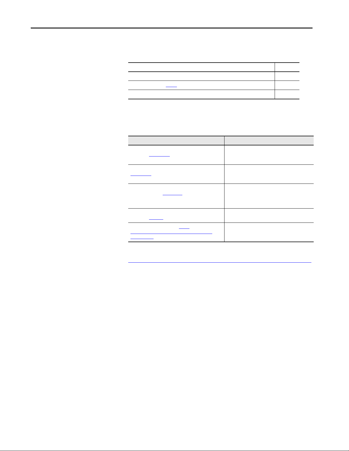
Summary of Changes
Additional Resources
This publication contains new and updated information as indicated in the
following table.
Top ic Pag es
Updated series reference for CU2 Control Units 11
Updated AC voltage in Tab le 5
Updated text 40 and 41
footnote 19
These documents contain additional information concerning related products
from Rockwell Automation.
Resource Description
Guardmaster EtherNet/IP Network Interface User Manual,
publication 440R-UM009
Guardmaster Safety Relays User Manual, publication
440R-UM013
System Design for the Control of Electrical Noise Reference
Manual, publication GMC-RM001
Industrial Automation Wiring and Grounding Guidelines,
publication 1770-4.1
Product Certifications website, http://
www.rockwellautomation.com/global/certification/
overview.page
Provides detailed information to install, wire,
configure, troubleshoot, and use the EtherNet/IP™
module.
Provides detailed information to install, wire,
configure, troubleshoot, and use Guardmaster safety
relays.
Provides a thorough review of the installation and
grounding of noisy components and what can be done
to minimize thei r potential for injecting noise into the
system.
Provides general guidelines for installing a
Rockwell Automation® industrial system.
Provides declarations of conformity, certificates, and
other certification details.
You can view or download publications at
http://www.rockwellautomation.com/global/literature-library/overview.page
To order paper copies of technical documentation, contact your local
Allen-Bradley distributor or Rockwell Automation sales representative.
.
6 Rockwell Automation Publication 440R-RM002B-EN-P - November 2018
Page 7

Chapter 1
Introduction
The next generation Guardmaster safety relay (GSR) family is a high-quality
replacement for most of the Minotaur™ safety relay (MSR) family.
The consistent 22.5 mm (0.9 in.) wide housing design and configurable
functions for reset and logic of GSR modules let you consolidate various
functions of MSR modules with fewer relays. These features help you reduce
your stocking requirements.
The MSR family of safety relays typically offers one dedicated safety function,
for each safety circuit and actuator. MSR solutions have less connectivity to
each other than GSR modules. If you add additional safety circuits, those
circuits require additional safety relay modules and safety contacts for
cascading to maintain PLd or PLe safety ratings according to EN ISO 13849-1
or SIL 2 or SIL 3 according to IEC 62061.
The GSR family of safety relays offers configurable safety functions and
consolidated safety circuits, which result in fewer units, less space, and less cost.
Due to the unique capability to cascade single-wire safety (SWS), logic
combinations and zones are constructed quickly.
A replacement with GSR modules is meant to be more than just a swap out.
New Machinery Directives have changed machine designs over the years.
These changes have harmonized standards and demands of safety solutions
that contribute to productivity and flexibility.
This publication offers detailed information to help with your conversion from
the legacy MSR family to a smarter and cost-effective machine design in
compliance with the latest requirements of Machinery Directive and
harmonized standards.
For further assistance in replacing those devices contact Rockwell Automation
Support, your local Allen-Bradley distributor, or Rockwell Automation sales
office.
Rockwell Automation Publication 440R-RM002B-EN-P - November 2018 7
Page 8

Chapter 1 Introduction
GSR Benefits
Conversion Concerns
The GSR family of safety relays provides the following benefits:
• One or two (dual-channel) inputs
•Single wire safety (SWS) expansion
• Narrow package (less panel space)
• Configurable operation
• Cat 4 PLe and SIL 3 rating on most models
•RoHS compliance
It is widely recognized that product obsolescence is a part of the industrial
business cycle. This publication provides cost-effective recommendations for
converting your MSR family of safety relays to the state-of-the-art GSR family,
and considers the following major concerns.
Panel Space
Many control panel designers leave space in their panels for future expansion
and improvements. If that extra panel space gets used, then panel space can
become tight. With panel space in mind, the recommended conversion is
intended to maintain, or even reduce, panel space.
Wiring Terminal Location
A wire that is moved from the top of the old device to the bottom of the new
device in a control panel cannot be taken lightly. Each of the recommended
conversions shows the terminal locations of the old and new devices, so you can
plan the conversion appropriately.
Wiring Change
Example schematics that compare the older device and the recommended
newer device are provided for each of the applications that the older device can
provide.
Response Time
Response time is the time that is required to perform the safety function. For
each conversion, the comparable response time is provided. An increase in the
response time requires you to adjust the safety distance. This increase is not as
much of an issue when a safety gate must be opened manually. However, this
additional response time is likely to be an issue when presence-sensing devices
like light curtains and safety mats are used.
8 Rockwell Automation Publication 440R-RM002B-EN-P - November 2018
Page 9

Introduction Chapter 1
S11
S12
S21
S22
S34A1 13
L11A2 142324
33
CR1 CR2
41
34 42Y32
GSR CI
440R-S13R2
RESET
0
MM
AM
+24V DC
24V Com
CR1 CR2
K1 K2
L1
K1
K2
L2 L3
M
CR1 and CR2 consist of: 700-HPSXZ24 (relay)
700-HN123 (base)
700-AD1LR (diode and status indicator)
700-HN119 (retainer)
Output Load Capability
Every safety relay has limitations on the amount of current the relay can switch
or carry. When the load exceeds the rating of the safety relay, interposing relays
can be used as shown in Figure 1
Figure 1 - Output Load Capability Using Interposing Relays
.
Rockwell Automation Publication 440R-RM002B-EN-P - November 2018 9
Page 10

Chapter 1 Introduction
Notes:
10 Rockwell Automation Publication 440R-RM002B-EN-P - November 2018
Page 11

CU2 Control Unit
Chapter 2
Figure 2 - CU2 Control Unit
We recommend replacing the CU2 control unit with a GLP (Series A 205 or
later) safety relay.
Both the CU2 control unit and GLP safety relay use two proximity sensors to
sense the motion of the hazard. The CU2 control unit uses one proximity
sensor with an NPN output and the second proximity sensor with a PNP
output. The GLP safety relay requires PNP outputs for both proximity sensors.
The GLP safety relay has a multi-position switch that lets you configure the
GLP safety relay functionality. Switch positions 5, 6, 7, and 8 reflect the
functionality of the CU2 control unit. Additional functionalities (Cat 1 stop,
safely-limited speed, single wire safety expansion, unlock request, reset, and
lock request) are achieved with logic settings 1, 2, 3, and 4.
The CU2 control unit offers automatic/manual reset with the Y1/Y2
terminals. When the GLP safety relay is configured for logic settings 5, 6, 7, or
8, the GLP safety relay ignores the S44 reset input and operates in automatic
mode.
Ta b l e 1
shows the recommended conversions. With 110/230V AC supply
voltages, many other Bulletin 1606 power supplies can be used. If voltage-free
contacts are needed, the single wire safety signal from the GLP safety relay can
drive the EM safety relay.
Table 1 - Conversion Table
Supply Voltage CU2 Cat. No. GLP Cat. No. EM Cat. No.
24V AC/DC 440R-S07139 440R-GL2S2P
110/230V AC 440R-S07140
Rockwell Automation Publication 440R-RM002B-EN-P - November 2018 11
440R-GL2S2P with
1606-XLP15E
440R-EM4R2
Page 12

Chapter 2 CU2 Control Unit
Terminal Location and
PanelSpace
The CU2 control unit is 45 mm (1.8 in.) wide and has one row of terminals at
the top and bottom. The GLP safety relay is only 22.5 mm (0.9 in.) wide and
has two rows of terminals at the top and bottom.
Figure 3 - DC Powered Terminals and Panel Space [mm (in.)]
22.5 (0.88)
45 (1.89)
S12 S22 AP S54
A1 A2 P12 P22
A1 N P N Y1 13 23 31
CU 2
A2 P N P Y2 14 24 32
73
(2.87)
GLP
L12 L11 Y32 S44
X14 X24 51 L61
119
(4.79)
The CU2 control unit can also be ordered with a 110/230V AC power supply.
Because the GLP safety relay is DC powered, a power supply (catalog number
1606-XLP15E) must be used to convert the AC supply to 24V DC. This
configuration occupies the same amount of space as one CU2 control unit.
Figure 4 - AC Powered Terminals and Panel Space [mm (in.)]
67.5 (2.66)
45 (1.89)
45 (1.89)
GLP
33 34 43 44
A1 A2
EM
L12 L11 X32
13 14 23 24
A1 N P N Y1 13 23 31
CU 2
A2 P N P Y2 14 24 32
73
(2.87)
+
DC 24-28V 15W
1606-
XLP15E
AC 100-240V
N L
S12 S22 AP S54
A1 A2 P12 P22
L12 L11 Y32 S44
X14 X24 51 L61
119
(4.79)
12 Rockwell Automation Publication 440R-RM002B-EN-P - November 2018
Page 13

CU2 Control Unit Chapter 2
12
22
21 33
34
11
TLS1-GD2
41
42
53
54A1
A2
K1 (aux)
K2 (aux)
Guard Closed
& Locked
Start
Stop
P
PP
N
Y1
Y2
A1
NPN
Proximity
Sensor
N
N
13
A2
1423243132
CU2
440R-S07139
+24V DC
24V Com
To PLC
To PLC
PNP
Proximity
Sensor
K2
K1
LOGIC SLS1
0
1
2
3
4
5
6
7
8
9
0
1
2
3
4
5
6
7
8
9
SLS2/TIME
0
1
2
3
4
5
6
7
8
9
GLP
440R-GL2S2P
A2S12 S22 L11
L12
L61
51
P12 P22
A1X14 X24 S44S54APY32
12
22
21 33
34
11
TLS1-GD2
41
42
53
54A1
A2
K1 (aux)
K2 (aux)
K1
K2
Guard Closed
& Locked
Start
Stop
K2
K1
Brown
Black
Black
Blue
Blue
Two PNP
Proximity
Sensors
L1
K1
K2
L2 L3
M
L1 L2 L3
M
12
22
21 33
34
11
TLS1-GD2
41
42
53
54A1
A2
K1 (aux)
K2 (aux)
Guard Closed
& Locked
Start
Stop
L1
115V AC
230V AC
+24V DC
L+
N-
24V Com
1606XLP15E
NPN
Proximity
Sensor
PNP
Proximity
Sensor
Two PNP
Proximity
Sensors
P
PP
N
Y1
Y2
A1 N
N
13
A2
1423243132
CU2
440R-S07139
N
To PLC
To PLC
K2
K1
LOGIC SLS1
0
1
2
3
4
5
6
7
8
9
0
1
2
3
4
5
6
7
8
9
SLS2/TIME
0
1
2
3
4
5
6
7
8
9
GLP
440R-GL2S2P
A2S12 S22 L11
L12
L61
51
P12 P22
A1X14 X24 S44S54APY32
12
22
21 33
34
11
TLS1-GD2
41
42
53
54A1
A2
K1 (aux)
K2 (aux)
K1
K2
Guard Closed
& Locked
Start
Stop
K2
K1
Brown
Black
Black
Blue
Blue
L1
K1
K2
L2 L3
M
L1 L2 L3
M
Wiring Schematics
The following schematics compare the wiring of your existing MSR module to
the recommended newer devices for each application that the existing device
provides.
DC Powered
Figure 5 - DC Powered Schematic
AC Powered
Figure 6 - AC Powered Schematic
Rockwell Automation Publication 440R-RM002B-EN-P - November 2018 13
Page 14
Chapter 2 CU2 Control Unit
NPN
Proximity
Sensor
PNP
Proximity
Sensor
Two PNP
Proximity
Sensors
L1
115V AC
230V AC
+24V DC
L+
N-
24V Com
1606XLP15E
P
PP
N
Y1
Y2
A1 N
N
13
A2
1423243132
CU2
440R-S07139
N
K1
K2
To PLC
To PLC
K2
K1
LOGIC SLS1
0
1
2
3
4
5
6
7
8
9
0
1
2
3
4
5
6
7
8
9
SLS2/TIME
0
1
2
3
4
5
6
7
8
9
GLP
440R-GL2S2P
A2S12 S22 L11
L12
L61
51
P12 P22
A1X14 X24 S44S54APY32
K2
K1
Brown
Black
Black
Blue
Blue
A1
L11
X32
L12 14 344424
13 33 4323
A2
EM
440R-EM4R2
Figure 7 - AC Powered Loads Schematic
Output Load Capability
The CU2 control unit has voltage-free output contacts, while the GLP safety
relay has solid-state outputs. The GLP safety relay can easily expand its output
capability with the single wire safety connection to an EM expansion relay,
which has voltage-free contacts. Use an interposing relay if additional current
capability is needed. Ta b l e 2
Table 2 - Current Capability
Load Type CU2 GLP EM
AC Inductive
DC
Thermal (non-switching) 4 A 0.5 A 1 x 6 A
shows the current capability of the three relays.
B300, AC-15
5 A/120,250V
DC-13
3 A/24V DC
—
0.5 A/24V DC
B300 AC-15
1.5 A / 250V AC
DC13
2 A/24V DC (0.1 Hz)
14 Rockwell Automation Publication 440R-RM002B-EN-P - November 2018
Page 15

MSR7R and MSR7C Safety Relay
Chapter 3
Figure 8 - MSR7R and MSR7C Safety Relay
We recommend replacing both the MSR7R and MSR7C safety relays with the
MSR125H/HP safety relay. The replacement catalog numbers are shown in
Ta b l e 3
. The MSR125H/HP safety relay is one of the MSR relays that will
remain available for five or more years.
The MSR7R and MSR7C safety relays are logic units for monitoring and
interfacing two-hand control devices with a safety-related circuit. The MSR7R
safety relay is for use with mechanical switches and Bulletin 800Z Zero-Force
Touch Buttons™. The MSR7C safety relay is for use with electronic-sensing (for
example, capacitive or photoelectric) palm buttons because the MSR7C safety
relay does not turn its output ON if a power interruption occurs while hands
are on the buttons.
Table 3 - Conversion Table
MSR125 Cat. No.
Type Supply Voltage MSR7 Cat. No.
24V DC
440R-D23021
440R-D23024
MSR7R
MSR7C
24V AC 440R-D23165
110/115V AC 440R-D23022 440R-D23164 440R-D23169
230V AC 440R-D23023 440R-D23163 440R-D23168
24V DC
24V AC 440R-D23165
110/115V AC 440R-D23025 440R-D23164 440R-D23169
230V AC 440R-D23026 440R-D23163 440R-D23168
Fixed Terminals Removable Terminals
440R-D23166 440R-D23171
440R-D23171 or
440R-D23170
440R-D23166 440R-D23171
440R-D23171 or
440R-D23170
ATT EN TI ON : A risk assessment must be performed when converting MSR7C
safety relay to MSR125 safety relay. The risk assessment must include an
evaluation of a hands-on-the-buttons during a power interruption.
Rockwell Automation Publication 440R-RM002B-EN-P - November 2018 15
Page 16

Chapter 3 MSR7R and MSR7C Safety Relay
A1 S13 S24 X1 41 13 13 33
A2 S14 S23 X2 42 14 24 34
45 (1.8)
MSR7
A1 S11 S12 S13
Y1 Y2 13 23
14 24
S21 S22 S23 A2
MSR125
22.5 (0.9)
99
(3.9)
73
(2.9)
23
S21 A2 Y214S22 S23
S11
A1S12 S13 13 Y1
24
MSR125
440R-D231**
24/110/230V
K1
K2
S1
S2
S1
S2
Ground
23
S13 A2 X214 34S14
33 41
42
S23
A1S24 13 X1
24
MSR7R
440R-D230**
K1 K2 K1 K2
K1
K2
Terminal Location and
PanelSpace
Wiring Schematics
The MSR7 safety relay is 45 mm (1.8 in.) wide and has one row of terminals at
the top and bottom. The MSR125 safety relay is only 22.5 mm (0.9 in.) wide
with two rows of terminals on the top and bottom.
The MSR125 safety relay is available with wither fixed or removable terminals;
the MSR7 safety relay only has fixed terminals.
Figure 9 - Terminals and Panel Space [mm (in.)]
The MSR7 and MSR125 safety relays are available in the following power
supplies:
• 24V AC
• 24V DC
• 110V AC
• 230V AC
The wiring schematics are the same for each voltage supply.
MSR7R
Figure 10 - MSR7R Schematic
16 Rockwell Automation Publication 440R-RM002B-EN-P - November 2018
Page 17

MSR7C
23
S21 A2 Y214S22 S23
S11
A1S12 S13 13 Y1
24
MSR125
440R-D231**
24/110/230V
K1
K2
S1
S2
S1
S2
Ground
23
S13 A2 X214 34S14
33 41
42
S23
A1S24 13 X1
24
MSR7C
440R-D230**
K1 K2
K1 K2
23
S13 A2 X214 34S14
33 41
42
S23
A1S24 13 X1
24
MSR7R
440R-D23021
or
440R-D23024
23
S21 A2 Y214S22 S23
S11
A1S12 S13 13 Y1
24
MSR125
440R-D23171
or
440R-D23166
24V DC
K1 K2 K3
S1
S2
Aux
S1
S2
Ground
K1 K2 K1 K2
K1
K2
K3
K3
Aux
K3
23
A2 X2 14 34 44
33 43 51 61
52 62
A1 13X1
24
MSR132E
440R-E23191
or
440R-E23097
Figure 11 - MSR7C Schematic
MSR7 — All Contacts Used
MSR7R and MSR7C Safety Relay Chapter 3
Maximum Input Impedance
Figure 12 - MSR125 with Expansion Relay
The MSR7 safety relay can tolerate up to 500 ohms of resistance on its input
circuits. The MSR125 safety relay is limited to 40 ohms. This difference is not
likely to be an issue as the typical cable resistance of 18 AWG (0.75 mm2) wire
is 20.95 ohms per 1000 meters (6.4 ohms per 1000 feet).
Rockwell Automation Publication 440R-RM002B-EN-P - November 2018 17
Page 18

Chapter 3 MSR7R and MSR7C Safety Relay
Response Time
Output Load Capability
Response time applies when at least one hand is removed from the two-hand
controls and the operator reaches towards the hazard.
If the MSR132 expansion relay is not used, the response time of the MSR125
safety relay is faster than the MSR7 safety relay, and the distance from the twohand controls to the hazard can remain unchanged.
If the MSR132 expansion relay is used, the response time of the relay is 20 ms
longer; the safety distance must be recalculated and the two-hand controls may
have to be moved further away from the hazard. Using the standard speed
constant of 1600 mm/sec (63 in./sec), the additional 20 ms requires an
additional 32 mm (1.25 in.) of spacing from the hazard.
Safety Relay Response Time
MSR7 50 ms
MSR125 20 ms
MSR132 50 ms
The MSR125 safety relay has a higher current capability than the MSR7
safety relay.
Table 4 - Current Capability
Load Type MSR7 MSR125 MSR132
AC Inductive
DC
Thermal (non-switching) 4 A
BC300, AC-15
4 A
P300, DC-13
2 A/24V DC
B300, AC-15
6 A
P300, DC-13
3 A/24V DC
1 x 6 A
2 x 4 A
AC-15
6 A
DC-13
3 A/24V DC
2 x 6 A
4 x 4 A
18 Rockwell Automation Publication 440R-RM002B-EN-P - November 2018
Page 19

MSR9T Safety Relay
Chapter 4
Figure 13 - MSR9T Safety Relay
Terminal Location and
PanelSpace
We recommend replacing the MSR9T safety relay with a Sipha™ 2 controller.
The replacement catalog numbers are shown in Ta b l e 5
.
The MSR9T safety relay was used in older applications, where the input device
employed the diversity concept of one normally closed contact and one
normally open contact. The Sipha 2 controller employs the same diversity
approach and can easily be applied to contact-type switches and the Sipha noncontact switches.
These controllers are similar in the type of inputs and the number of outputs.
Table 5 - Conversion Table
Supply Voltage MSR9T Cat. No. Sipha 2 Cat. No.
(1)
24V AC/DC
110/230V AC 440R-F23028
(1) For 24V, the Sipha 2 controller can only operate at 24V DC. When the MSR9T is powered by
115/230V AC, you must provide an AC/DC converter.
440R-F23027
440N-S32021
The MSR9T safety relay and Sipha 2 controller are both 45 mm (1.8 in.) wide
and have one row of terminals at the top and bottom.
There is a significant difference in the location of the terminals for the power,
inputs, outputs, and monitoring. Numerous wires must be moved from the top
of the relay to the bottom and vice versa.
Figure 14 - Terminals and Panel Space [mm (in.)]
45 (1.8)
A1 A2 X1 X2
MSR9T Sipha 2
31 32 13 14 23 24 S21 S22
Rockwell Automation Publication 440R-RM002B-EN-P - November 2018 19
S13 S14 A1 + X1 2 1 13 23 31
45 (1.8)
230/
24V
110
AC/DC
230/
24V
110
AC/DC
A2 - X2 3 4 14 24 32
Page 20

Chapter 4 MSR9T Safety Relay
Sipha 2
440N-S32021
23
3
A2 X2144
31
32
1
A1 +213X1
24
MSR9
440R-F23027
23
S13 A2 X214S14
31
32
S21
A1S22 13 X1
24
Closed
24V DC
Ground
K1
K2
Open
K1 K2
Closed
K1
K2
Open
K1 K2
Sipha 2
440N-S32021
23
3
A2 X2144
31
32
1
A1 +213X1
24
MSR9
440R-F23028
23
S13 A2 X214S14
31
32
S21
A1S22 13 X1
24
Closed
110/115/230V AC
Neutral
115
230
K1
K2
Open
K1 K2
Closed
K1
K2
Open
K1 K2
110
230
Wiring Schematics
The following schematics compare the wiring of your existing MSR module to
the recommended newer devices for each application that the existing device
provides.
24V AC/DC Powered
When powered by 24V AC/DC, the power supply connections are made to +
and – terminals of the Sipha controller; the A1 and A2 terminals must have no
connections.
Figure 15 - 24V AC/DC Powered Schematic
110/115/230V AC Powered
An internal, user-selectable switch is used to set the input voltage of both the
MSR9 safety relay and Sipha 2 controller. Remove the front cover and set the
switch to either 110/115V or 230V AC. Figure 16
schematics; in this case the power to the relay is connected to A1 and A2.
Figure 16 - AC Powered
shows the conversion
20 Rockwell Automation Publication 440R-RM002B-EN-P - November 2018
Page 21

MSR9T Safety Relay Chapter 4
Maximum Input Impedance
Input Simultaneity
The MSR9T tolerates up to 500 ohms of resistance on its input circuits. The
Sipha 2 controller tolerates 200 ohms on terminals 1…4 and 150 ohms on
terminals 2…3. This difference is not likely to be an issue as the typical cable
resistance of 18 AWG (0.75 mm2) wire is 20.95 ohms per 1000 meters
(6.4 ohms per 1000 feet).
Input simultaneity is a measure of the difference in time between the change in
state of the two channels to enable the relay to energize its outputs.
The MSR9T safety relay is specified to have input simultaneity of 500 ms; the
dual-inputs must change state with 500 ms of each other. The Sipha 2
controller has historically been specified with a minimum approach speed of
17 mm/s (0.67 in./s).
The following describes how a Sipha 2 controller works:
• If the N.O. contact opens first, then the N.C. contact can close at any
time afterwards.
• If the N.C. contact closes first, then the N.O. contact must open within
1.4 seconds.
Response Time
Output Load Capability
Because the response time of the Sipha 2 controller is faster than the MSR9T
safety relay, the safety distance calculation does not require recalculation.
Safety Relay Response Time
MSR9T 50 ms
Sipha 2 40 ms
Ta b l e 6 compares the output load capability of the MSR9T to the replacement
relays. See Output Load Capability on page 9
for a wiring example of using
interposing relays for applications where the load exceeds the capability of the
replacements.
Table 6 - Current Capability
Load Type MSR9T Sipha 2
AC Inductive
DC
Thermal (non-switching) 4 A —
B300, AC-15
4 A/250V AC
4 A/120V AC
P300, DC-13
3 A/24V DC
B300, AC-15
4 A/250V AC
P300, DC-15
2 A/24V DC
Rockwell Automation Publication 440R-RM002B-EN-P - November 2018 21
Page 22

Chapter 4 MSR9T Safety Relay
Notes:
22 Rockwell Automation Publication 440R-RM002B-EN-P - November 2018
Page 23

MSR33 Safety Relay
Chapter 5
Figure 17 - MSR33 Safety Relay
Terminal Location and
PanelSpace
We recommend replacing the MSR33 safety relay with a Sipha 2 controller.
The MSR33 safety relay is offered with either fixed or removable terminals.
The Sipha 2 controller only has fixed terminals. The MSR33 safety relay has
solid-state outputs, while the Sipha 2 controller has electromechanical outputs.
The MSR33 safety relay has a feature that is called Startup Test. The wiring
configures the startup test. Upon initial power-up, the input device must be
cycled once to energize the safety outputs. The Sipha 2 controller does not
support this feature.
Table 7 - Conversion Table
Ter min al s MSR33 Cat. No. Sipha 2 Cat. No.
Fixed 440R-F23199
Removable 440R-F23200
440N-S32021
(only fixed terminals)
The Sipha 2 controller requires twice as much panel space as its width is 45 mm
(1.8 in.) compared to the 22.5 mm (0.9 in.) for the MSR33 safety relay. The
difference in relay height must be considered but is not significant.
The terminal locations for the inputs, outputs, and monitoring circuits require
movement of the wiring from the top to the bottom of the relay and vice versa.
Figure 18 - Terminals and Panel Space [mm (in.)]
22.5 (0.9)
45 (1.8)
A1 Y41 S11 S34
99
MSR33
A2 S12 S22 Y32
14 24 S21 Y2
Rockwell Automation Publication 440R-RM002B-EN-P - November 2018 23
(3.9)
A1 + X1 2 1 13 23 31
230/
24V
110
AC/DC
Sipha 2
230/
24V
110
AC/DC
A2 - X2 3 4 14 24 32
73
(2.9)
Page 24

Chapter 5 MSR33 Safety Relay
Sipha 2
440N-S32021
23
3
A2 X2144
31
32
1
A1 +213X1
24
MSR33
440R-F23***
Y41
S12 A2 14S22
Y2
Y32
S11 A1
S21 S34
24
Closed
24V DC
Ground
K1
Reset
K2
Open
K1 K2
Closed
K1
K2
Open
K1 K2
Reset
Sipha 2
440N-S32021
23
3
A2 X2144
31
32
1
A1 +213X1
24
MSR33
440R-F23***
Y41
S12 A2 14S22
Y2
Y32
S11
A1S21 S34
24
Closed
24V DC
Ground
K1
K2
Open
K1 K2
Closed
K1
K2
Open
K1 K2
Wiring Schematics
The following schematics compare the wiring of your existing MSR module to
the recommended newer devices for each application that the existing device
provides.
Manual Reset
In the manual reset examples, the MSR33 safety relay has monitored reset,
where the Reset button must be pressed and released. The reset action occurs
when the button is released. With the Sipha 2 controller, the reset occurs when
the button is pressed.
Figure 19 - Manual Reset
Automatic Reset
Figure 20 - Automatic Reset
24 Rockwell Automation Publication 440R-RM002B-EN-P - November 2018
Page 25

MSR33 Safety Relay Chapter 5
Auxiliary Output
The auxiliary output of the MSR33 is normally open. When the safety outputs
are OFF, the auxiliary output is OFF.
The Sipha 2 auxiliary output is normally closed. When the safety outputs are
open (OFF), the auxiliary output is closed (ON).
Input Simultaneity
Response Time
Input simultaneity is a measure of the difference in time between the changes
in state of the two channels to enable the relay to energize its outputs.
The MSR33 safety relay allows an infinite amount of time between the
changes of state of the two inputs. The Sipha 2 controller has historically been
specified with a minimum approach speed of 17 mm/s (0.67 in./s).
The following describes how a Sipha 2 controller works:
• If the N.O. contact opens first, then the N.C. contact can close at any
time afterwards.
• If the N.C. contact closes first, then the N.O. contact must open with
1.4 seconds.
ATT EN TI ON : Because the response time of the MSR33 safety relay is 25 ms
faster than the Sipha 2 controller, the safety distance must be examined
closely and adjusted, if necessary.
Safety Relay Response Time
MSR33 15 ms
Sipha 2 40 ms
Output Load Capability
The load capability table only compares DC loads because the MSR33 safety
relay can only accommodate DC loads.
Table 8 - Current Capability
Load Type MSR33 Sipha 2
DC 2 A/24V DC 2 A/24V DC
Rockwell Automation Publication 440R-RM002B-EN-P - November 2018 25
Page 26

Chapter 5 MSR33 Safety Relay
Notes:
26 Rockwell Automation Publication 440R-RM002B-EN-P - November 2018
Page 27

MSR35 Safety Relay
A1 Y41 S11 S34
14 24 S21 Y2
A2 S12 S22 Y32
MSR35
22.5 (0.9)
99
(3.9)
A1 S11 S12 S13
Y1 Y2 13 23
14 24
S21 S22 S23 A2
MSR125
22.5 (0.9)
99
(3.9)
Chapter 6
Figure 21 - MSR35 Safety Relay
Terminal Location and
PanelSpace
We recommend replacing the MSR35 safety relay with an MSR125 safety
relay. The MSR125H/HP safety relay is one of the MSR relays that will remain
available for five or more years.
The MSR35H/HP safety relay is an electronic two-hand control relay that is
offered with either fixed or removable terminals. It is only available with
24V DC power.
Table 9 - Conversion Table
Ter min al s MSR35 Cat. No. MSR125 Cat. No.
Fixed 440R-D23201 440R-D23171
Removable 440R-D23202 440R-D23166
The MSR35RT safety relay has a 22.5 mm (0.9 in.) wide body, with two rows
of terminals at the top and bottom. The MSR125 safety relay also has two rows
of terminals at the top and bottom and is 22.5 mm (0.9 in.) wide.
Figure 22 - Terminals and Panel Space [mm (in.)]
Rockwell Automation Publication 440R-RM002B-EN-P - November 2018 27
Page 28

Chapter 6 MSR35 Safety Relay
23
S21 A2 Y214S22 S23
S11
A1S12 S13 13 Y1
24
MSR125
440R-D231**
24V DC
K1
K2
S1
S2
Ground
K1 K2
S1
S2
MSR35
440R-D232**
Y41
S12 A2 14S22
Y2
Y32
S11 A1
S21 S34
24
K1
K2
K1 K2
Wiring Schematics
The output is a significant difference between the two relays. The MSR35
safety relay has solid-state outputs, while the MSR125 safety relay has
voltage-free contacts.
Category IIIC
Figure 23 - Category IIIC Per EN574
24V DC
K1
S1
S2
Ground
S11 A1
S21 S34
MSR35
440R-D232**
S12 A2 14S22
K1 K2
Y41
24
K2
Y2
Y32
S1
S11
MSR125
440R-D231**
S21 A2 Y214S22 S23
S2
A1S12 S13 13 Y1
23
24
K1 K2
K1
K2
Category IIIA
Figure 24 - Category IIIA Per EN574
28 Rockwell Automation Publication 440R-RM002B-EN-P - November 2018
Page 29

MSR35 Safety Relay Chapter 6
Response Time
Output Load Capability
ATT EN TI ON : Because the response time of the MSR35RT is faster than the
MSR125 relay, the safety distance must be examined closely and adjusted if
necessary.
Safety Relay Response Time
MSR35 15 ms
MSR125 20 ms
The MSR125 safety relay has a higher current capability than the
MSR35H/HP safety relay, as shown in Ta b l e 1 0
Table 10 - Current Capability
Load Type MSR35 MSR125
DC 2 A/24V DC 3 A/24V DC
.
Rockwell Automation Publication 440R-RM002B-EN-P - November 2018 29
Page 30

Chapter 6 MSR35 Safety Relay
Notes:
30 Rockwell Automation Publication 440R-RM002B-EN-P - November 2018
Page 31

MSR121RT Safety Relay
Chapter 7
Figure 25 - MSR121RT Safety Relay
Terminal Location and
PanelSpace
We recommend replacing the MSR121RT safety relay with a CI safety relay.
The MSR121RT safety relay can be wired for automatic or monitored reset.
The CI safety relay is configured for automatic or monitored reset by a rotary
switch on its front face.
The MSR121RT safety relay is only available with a 24V AC/DC power
supply.
Table 11 - Conversion Table
Supply Voltage MSR121RT Cat. No. CI Cat. No.
(1)
24V AC/DC
(1) For 24V, the CI safety relays can only operate at 24V DC. When the MSR121RT is powered by
24V AC, you must provide an AC/DC converter.
440R-J23102 440R-S13R2
The MSR121RT safety relay has a 55 mm (2.17 in.) wide body, with one row
of terminals at the top and one at the bottom. The CI safety relay has a
22.5 mm (0.9 in.) wide body with two rows of terminals at the top and bottom.
Figure 26 - Terminals and Panel Space [mm (in.)]
22.5 (0.9)
55 (2.17)
13 23 33 41
A1 S11 S12 L11
A1 S11 S52 S12 Y31 Y32 13 23 33 41
MSR121R/T
S21 S22 X5 S33 S34 14 24 34 42 A2
Rockwell Automation Publication 440R-RM002B-EN-P - November 2018 31
75
(2.95)
CI
S21 S22 S34 A2
14 24 34 42
119
(4.69)
Page 32

Chapter 7 MSR121RT Safety Relay
S11 S12
S21
S52
S22
S34
S33
A1
X5
13Y31
A2 142324
33 41
34 42Y32
MSR121RT
440R-J23102
Reset
K1
K2
Reset
S11
S12
S21
S22
S34A1 13
L11A2 142324
33 41
34 42Y32
GSR CI
440R-S13R2
RESET
0
MM
AM
+24V DC
24V Com
K2K1 K2K1
K1
K2
S11 S12
S21
S52
S22
S34
S33
A1
X5
13Y31
A2 142324
33 41
34 42Y32
MSR121RT
440R-J23102
S11
S12
S21
S22
S34A1 13
L11A2 142324
33 41
34 42Y32
GSR CI
440R-S13R2
RESET
0
MM
AM
+24V DC
24V Com
K2K1 K2K1
Stop
Start
K1
K2
Stop
Start
K1
K2
K1
K2
K1 K2
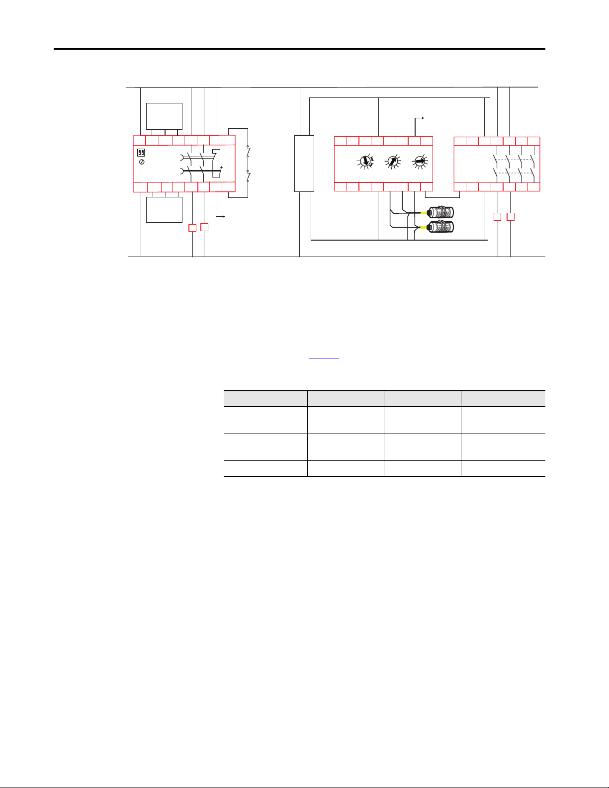
Wiring Schematics
The following schematics compare the wiring of your existing MSR module to
the recommended newer devices for each application that the existing device
provides.
Dual Channel Input
Figure 27 - Monitored Reset
Figure 28 - Automatic Reset
32 Rockwell Automation Publication 440R-RM002B-EN-P - November 2018
Page 33

Single Channel Input
S11 S12
S21
S52
S22
S34
S33
A1
X5
13Y31
A2 142324
33 41
34 42Y32
MSR121RT
440R-J23102
S11
S12
S21
S22
S34A1 13
L11A2 142324
33 41
34 42Y32
GSR CI
440R-S13R2
RESET
0
MM
AM
+24V DC
24V Com
K2K1 K2K1
Reset
K1
K2
Reset
K1
K2
S11 S12
S21
S52
S22
S34
S33
A1
X5
13Y31
A2 142324
33 41
34 42Y32
MSR121RT
440R-J23102
S11
S12
S21
S22
S34A1 13
L11A2 142324
33 41
34 42Y32
GSR CI
440R-S13R2
RESET
0
MM
AM
+24V DC
24V Com
K2K1 K2K1
Stop
Start
K1
K2
Stop
Start
K1
K2
K1
K2
K1 K2
Figure 29 - Monitored Reset
Figure 30 - Automatic Reset
MSR121RT Safety Relay Chapter 7
Rockwell Automation Publication 440R-RM002B-EN-P - November 2018 33
Page 34

Chapter 7 MSR121RT Safety Relay
S11 S12
S21
S52
S22
S34
S33
A1
X5
13Y31
A2 142324
33 41
34 42Y32
MSR121RT
440R-J23102
Reset
S11
S21
S12
S22
S34A1 13
L11A2 142324
33 41
34 42Y32
GSR CI
440R-S13R2
RESET
0
MM
AM
+24V DC
24V Com
K2K1 K2K1
Light curtain
Safezone, SC300
SensaGuard
OSSD1 OSSD2
Light curtain
Safezone, SC300
SensaGuard
OSSD1 OSSD2
K1
K2
Reset
K1
K2
S11 S12
S21
S52
S22
S34
S33
A1
X5
13Y31
A2 142324
33 41
34 42Y32
MSR121RT
440R-J23102
S11
S21
S12
S22
S34A1 13
L11A2 142324
33 41
34 42Y32
GSR CI
440R-S13R2
RESET
0
MM
AM
+24V DC
24V Com
K2K1 K2K1
Light curtain
Safezone, SC300
SensaGuard
OSSD1 OSSD2
Light curtain
Safezone, SC300
SensaGuard
OSSD1 OSSD2
Stop
Start
K1
K2
Stop
Start
K1
K2
K1
K2
K1 K2
OSSD Input
Figure 31 - Monitored Reset
Figure 32 - Automatic Reset
34 Rockwell Automation Publication 440R-RM002B-EN-P - November 2018
Page 35

Safety Mat Input
S11 S12
S21
S52
S22
S34
S33
A1
X5
13Y31
A2 142324
33 41
34 42Y32
MSR121RT
440R-J23102
Reset
S11
S21
S12
S22
S34A1 13
L11A2 142324
33 41
34 42Y32
GSR CI
440R-S13R2
RESET
0
MM
AM
+24V DC
24V Com
K2K1 K2K1
Safety
Mat
Safety
Mat
K1
K2
Reset
K1
K2
S11 S12
S21
S52
S22
S34
S33
A1
X5
13Y31
A2 142324
33 41
34 42Y32
MSR121RT
440R-J23102
S11
S21
S12
S22
S34A1 13
L11A2 142324
33 41
34 42Y32
GSR CI
440R-S13R2
RESET
0
MM
AM
+24V DC
24V Com
K2K1 K2K1
Safety
Mat
Safety
Mat
Stop
Start
K1
K2
Stop
Start
K1
K2
K1
K2
K1 K2
Figure 33 - Monitored Reset
MSR121RT Safety Relay Chapter 7
Response Time
Figure 34 - Automatic Reset
ATT EN TI ON : Because the response time of the MSR121RT safety relay is
faster than the CI safety relay, the safety distance must be examined closely
and adjusted if necessary.
Safety Relay Response Time
MSR121RT 15 ms (24V AC/DC)
CI 35 ms (mechanic al and OSSD inputs);
45 ms (safety mat inputs)
Rockwell Automation Publication 440R-RM002B-EN-P - November 2018 35
Page 36

Chapter 7 MSR121RT Safety Relay
Output Load Capability
The MSR121RT safety relay has a higher current capability than the CI safety
relay, as shown in Ta b l e 1 2
. See Output Load Capability on page 9 for a wiring
example of using interposing relays for applications where the load exceeds the
CI safety relay capability.
Table 12 - Current Capability
Load Type MSR121RT CI
AC Inductive
DC
Thermal (non-switching) 6 A 2 A
B300, AC-15
6 A/250V AC
R300, DC-13
6 A/240V DC
C300, AC-15
1.5 A
2 A @ 24V DC
36 Rockwell Automation Publication 440R-RM002B-EN-P - November 2018
Page 37

MSR124RT Safety Relay
Chapter 8
Figure 35 - MSR124RT Safety Relay
We recommend replacing the MSR124RT safety relay with a CI and EM
safety relay.
The MSR124RT has the following design characteristics:
•Single- or dual-channel inputs
• Can accommodate mechanical and OSSD (light curtain) inputs
• Five electromechanical safety outputs
• One solid-state auxiliary output
• Reset can operate automatically or monitored manual.
The MSR124RT safety relay is a safety monitoring relay that provides versatile
inputs and monitoring capability with many safety outputs in a 100 mm
(3.93 in.) package.
The MSR124RT safety relay can be connected as either a single- or dualchannel safety gate or E-stop. It can also be connected to a light curtain that
provides cross fault detection.
The wiring configuration determines the Reset and output monitoring.
Automatic/manual reset can use a jumper or can be used to check operation of
the contacts. Monitored manual requires the use of a manually operated
normally open momentary switch to activate the outputs.
The outputs include five normally open safety rated outputs and one auxiliary
output. The safety outputs have independent and redundant internal contacts
to help verify the safety function. The auxiliary output is not safety rated and
must only be used for indication purposes.
Table 13 - Conversion Table
Supply Voltage MSR124 Cat. No. CI Cat. No. EM Cat. No.
24V AC/DC
115V AC/ 24V DC 440R-G23108
230V AC/24V DC 440R-G23107
(1) For 24V, the C I and EM safet y relays can o nly operate at 2 4V DC. When the M SR124RT is powe red by 24V AC, you must provide a n
AC/DC converte r.
Rockwell Automation Publication 440R-RM002B-EN-P - November 2018 37
(1)
440R-G23110
440R-S13R2 440R-EM4R2
Power Supply
Cat. No.
—
1606-XLP15E
Page 38

Chapter 8 MSR124RT Safety Relay
100 (3.93)
75
(2.95)
13 23 33 41
A1 S11 S12 L11
S21 S22 S34 A2
14 24 34 42
CI
1606-
XLP15E
MSR124RT
A1 S11 S12 S21 S23 S22 S12
A3+
13 23 33 43 53 81 A4
PE
Y1 Y2 (-) X1 X2
X5 X6 14 24 34 44 54 82 A2
45 (1.89)
119
(4.79)
67.5 (2.66)
33 34 43 44
A1 A2
L12 L11 X32
13 14 23 24
EM
+
N L
AC 100-240V
DC 24-28V 15W
S11
S12
S21
S22
S34A1
K1
K2
K3K4
K5
13
L11A2 142324
33 41
34 42Y32
GSR CI
440R-S13R2
RESET
0
MM
AM
S11PES12 S22S21
Y1 X5 X6
X1
K1
K2
K3
K4
K5
A1S23
To PLC
+24V DC
24V Com
A3+ 13
A4-A2Y2 142324
33 81
34 82 X2
MSR124RT
440R-G23110
434453
54
Reset
K3 K4 K5K1 K2
To PLC
A1
L11
X32
L12 14 34 4424
13 33 4323
A2
GSR EM
440R-EM4R2
K1 K2 K3
K4 K5
Reset
Terminal Location and
PanelSpace
For DC applications, the combination of the CI and EM safety relay is smaller
than the MSR124RT safety relay. For AC applications, a 1606-XLP15E power
supply can be used; this combination still occupies less panel space than an
MSR124RT safety relay.
Figure 36 - Terminals and Panel Space [mm (in.)]
Wiring Schematics
38 Rockwell Automation Publication 440R-RM002B-EN-P - November 2018
The following schematics compare the wiring of your existing MSR module to
the recommended newer devices for each application that the existing device
provides.
Dual Channel
Figure 37 - Monitored Reset, DC Powered
Page 39

Figure 38 - Automatic Reset, DC Powered
S11
S12
S21
S22
S34A1
K1
K2
K3K4
K5
13
L11A2 142324
33 41
34 42Y32
GSR CI
440R-S13R2
RESET
0
MM
AM
S11PES12 S22S21
Y1 X5 X6
X1
K1
K2
K3
K4
K5
A1S23
To PLC
+24V DC
24V Com
A3+ 13
A4-A2Y2 142324
33 81
34 82 X2
MSR124RT
440R-G23110
434453
54
K3 K4 K5K1 K2
To PLC
A1
L11
X32
L12 14 34 4424
13 33 4323
A2
GSR EM
440R-EM4R2
K1 K2 K3
K4 K5
S11
S12
S21
S22
S34A1
K1
K2
K3K4
K5
13
L11A2 142324
33 41
34 42Y32
GSR CI
440R-S13R2
RESET
0
MM
AM
S11PES12 S22S21
Y1 X5 X6
X1
K1
K2
K3
K4
K5
A1S23
To PLC
+24V DC
24V Com
A3+ 13
A4-A2Y2 142324
33 81
34 82 X2
MSR124RT
440R-G23110
434453
54
Reset
Reset
K3 K4 K5K1 K2
To PLC
A1
L11
X32
L12 14 34 4424
13 33 4323
A2
GSR EM
440R-EM4R2
K1 K2 K3
K4 K5
S11
S12
S21
S22
S34A1
K1
K2
K3K4
K5
13
L11A2 142324
33 41
34 42Y32
GSR CI
440R-S13R2
RESET
0
MM
AM
S11PES12 S22S21
Y1 X5 X6
X1
K1
K2
K3
K4
K5
A1S23
To PLC
+24V DC
24V Com
A3+ 13
A4-A2Y2 142324
33 81
34 82 X2
MSR124RT
440R-G23110
434453
54
K3 K4 K5K1 K2
To PLC
A1
L11
X32
L12 14 34 4424
13 33 4323
A2
GSR EM
440R-EM4R2
K1 K2 K3
K4 K5
Single Channel
Figure 39 - Monitored Reset, DC Powered
MSR124RT Safety Relay Chapter 8
Figure 40 - Automatic Reset, DC Powered
Rockwell Automation Publication 440R-RM002B-EN-P - November 2018 39
Page 40

Chapter 8 MSR124RT Safety Relay
S11
S12
S21
S22
S34A1
K1
K2
K3K4
K5
13
L11A2 142324
33 41
34 42Y32
GSR CI
440R-S13R2
RESET
0
MM
AM
S11PES12 S22S21
Y1 X5 X6
X1
K1
K2
K3
K4
K5
A1S23
To PLC
+24V DC
24V Com
A3+ 13
A4-A2Y2 142324
33 81
34 82 X2
MSR124RT
440R-G23110
434453
54
Reset
K3 K4 K5K1 K2
To PLC
A1
L11
X32
L12 14 34 4424
13 33 4323
A2
GSR EM
440R-EM4R2
K1 K2 K3
K4 K5
Reset
Light curtain
Safezone, SC300
SensaGuard
OSSD1 OSSD2
Light curtain
Safezone, SC300
SensaGuard
OSSD1 OSSD2
S11
S12
S21
S22
S34A1
K1
K2
K3K4
K5
13
L11A2 142324
33 41
34 42Y32
GSR CI
440R-S13R2
RESET
0
MM
AM
S11PES12 S22S21
Y1 X5 X6
X1
K1
K2
K3
K4
K5
A1S23
To PLC
+24V DC
24V Com
A3+ 13
A4-A2Y2 142324
33 81
34 82 X2
MSR124RT
440R-G23110
434453
54
K3 K4 K5K1 K2
To PLC
A1
L11
X32
L12 14 34 4424
13 33 4323
A2
GSR EM
440R-EM4R2
K1 K2 K3
K4 K5
Light curtain
Safezone, SC300
SensaGuard
OSSD1 OSSD2
Light curtain
Safezone, SC300
SensaGuard
OSSD1 OSSD2
120V or
240V AC
V AC Com
S11
S12
S21
S22
S34A1
K1
K2
K3K4
K5
13
L11A2 142324
33 41
34 42Y32
GSR CI
440R-S13R2
RESET
0
MM
AM
S11PES12 S22S21
Y1 X5 X6
X1
K1
K2
K3
K4
K5
A1S23
To PLC
A3+ 13
A4-A2Y2 142324
33 81
34 82 X2
MSR124RT
440R-G23108
440R-G23107
434453
54
Reset
K3 K4 K5K1 K2
To PLC
A1
L11
X32
L12 14 34 4424
13 33 4323
A2
GSR EM
440R-EM4R2
K1 K2 K3
K4 K5
Reset
+24V DC
L+
N-
24V Com
1606XLP15E
OSSD Inputs
Figure 41 - Monitored Reset, DC Powered
Figure 42 - Automatic Reset, DC Powered
40 Rockwell Automation Publication 440R-RM002B-EN-P - November 2018
AC Powered
A Bulletin 1606-XLP15E power supply can be used to provide the 24V DC to
power the CI and EM safety relays.
Figure 43 - AC Powered
Page 41

MSR124RT Safety Relay Chapter 8
Ambient Temperature (°C)
Current² x number of contacts paths, (A²)
Response Time
Output Load Capability
ATT EN TI ON : Because the MSR124RT safety relay is faster than the CI and EM
safety relays, the safety distance must be examined closely and adjusted if
necessary.
Safety Relay Response Time
MSR124RT 20 ms
CI 35 ms for the inputs, and 25
EM 35 ms
ms for the SWS to the EM
For example, the total response time of the EM safety relay is 25 + 35 = 60 ms.
The outputs of the CI safety relay may require interposing relays, depending in
the load being switched by the MSR124RT safety relay. See Output Load
Capability on page 9 for a wiring example of using interposing relays for
applications where the load exceeds the capability of the CI or EM safety relay.
Table 14 - Current Capability
Load Type MSR124RT CI EM
AC Inductive
DC
Thermal (non-switching)
A300, AC-15
5 A/250V AC
N300, DC-13
4 A @ 24V DC
10 A (max in one circuit)
See current limit curve in
Figure 4 4
C300, AC-15
1.5 A/250V AC
DC-13
2 A/24V DC
1 x 6 A 2 A
2 x B300, AC-15
4 A/250V AC
P300, DC-13
2 A/24V DC
The current through all contacts in the MSR124RT safety relay must be
adjusted to its current limit curve, which is shown in Figure 44
Figure 44 - Current Limit Curve
Rockwell Automation Publication 440R-RM002B-EN-P - November 2018 41
.
Page 42

Chapter 8 MSR124RT Safety Relay
Notes:
42 Rockwell Automation Publication 440R-RM002B-EN-P - November 2018
Page 43

Index
B
benefit
8
GSR
C
capability
output load
change
8
wiring
concern
conversion
control unit
CU2
conversion
concern
CU2
control unit
current capability
CU2
MSR121RT 36
MSR124RT
MSR33
MSR35 29
MSR7C
MSR7R
MSR9T 21
8
11
8
11
14
41
25
18
18
M
MSR121RT
response time
safety relay
MSR124RT
response time
safety relay 37
9
MSR33
input simultaneity
response time
safety relay 23
MSR35
response time
safety relay
MSR7C
input impedance
response time
safety relay
MSR7R
input impedance
response time
safety relay
MSR9T
input impedance
input simultaneity
response time
safety relay 19
35
31
41
25
25
29
27
17
18
15
17
18
15
21
21
21
G
GSR
8
benefit
I
input impedance
17
MSR7C
MSR7R
17
MSR9T
MSR33
MSR9T
21
25
21
7
input simultaneity
introduction
L
location
wiring terminal
CU2
12
MSR121RT
MSR124RT 38
MSR33
MSR35
MSR7C 16
MSR7R
MSR9T
19
23
27
16
O
output load capability 9
14
CU2
MSR121RT
MSR124RT 41
MSR33
MSR35
MSR7C 18
MSR7R
MSR9T
36
25
29
18
21
P
panel space 8
12
CU2
MSR121RT
MSR124RT 38
MSR33
MSR35
8
31
MSR7C 16
MSR7R
MSR9T
31
23
27
16
19
Rockwell Automation Publication 440R-RM002B-EN-P - November 2018 43
Page 44

Index
R
response time 8
MSR121RT
MSR124RT
MSR33
25
29
MSR35
MSR7C
18
MSR7R
18
MSR9T 21
S
safety relay
MSR121RT
MSR124RT 37
MSR33
23
MSR35
27
MSR7C 15
MSR7R
15
MSR9T
wiring
CU2
MSR121RT
MSR124RT 38
MSR33
MSR35
MSR7C 16
MSR7R
MSR9T
8
panel
CU2
MSR121RT
MSR124RT 38
MSR33
MSR35
MSR7C 16
MSR7R
MSR9T
19
schematic
space
13
12
35
41
31
24
28
16
20
23
27
16
19
32
31
T
terminal location
12
CU2
MSR121RT
MSR124RT
MSR33
MSR35
MSR7C
MSR7R 16
MSR9T
time
response
31
38
23
27
16
19
8
W
wiring
8
change
terminal location
wiring schematic
13
CU2
AC powered
DC powered
MSR121RT 32
dual channel input
OSSD input
safety mat input 35
single channel input
MSR124RT
MSR33
MSR35
MSR7C
MSR7R
MSR9T 20
38
AC powered 40
dual channel
OSSD inputs
single channel 39
24
automatic reset
auxiliary output 25
manual reset
28
category IIIA 28
category IIIC
16
16
110/115/230V AC powered
24V AC/DC powered
8
13
13
32
34
33
38
40
24
24
28
20
20
44 Rockwell Automation Publication 440R-RM002B-EN-P - November 2018
Page 45

Page 46

Rockwell Automation Support
Use the following resources to access support information.
Documentation Feedback
Your comments will help us serve your documentation needs better. If you have any suggestions on how to improve this document, complete the
How Are We Doing? form at http://literature.rockwellautomation.com/idc/groups/literature/documents/du/ra-du002_-en-e.pdf
.
Technical Support Center
Knowledgebase Articles, How-to Videos, FAQs, Chat, User
Forums, and Product Notification Updates.
https://rockwellautomation.custhelp.com/
Local Technical Support Phone Numbers Locate the phone number for your country. http://www.rockwellautomation.com/global/support/get-support-now.page
Direct Dial Codes
Find the Direct Dial Code for your product. Use the code to
route your call directly to a technical support engineer.
http://www.rockwellautomation.com/global/support/direct-dial.page
Literature Library
Installation Instructions, Manuals, Brochures, and
Technical Data.
http://www.rockwellautomation.com/global/literature-library/overview.page
Product Compatibility and Download
Center (PCDC)
Get help determining how products interact, check
features and capabilities, and find associated firmware.
http://www.rockwellautomation.com/global/support/pcdc.page
.
Rockwell Otomasyon Ticaret A.Ş., Kar Plaza İş Merkezi E Blok Kat:6 34752 İçerenköy, İstanbul, Tel: +90 (216) 5698400
Rockwell Automation maintains current product environmental information on its website at http://ww w.rockwellautomation.com/rockwellautomation/about-us/sustainability-ethics/product-environmental-compliance.page.
Allen-Bradley, Guardmaster, Minotaur, Rockwell Automation, Rockwell Software, Sipha, and Zero-Force Touch Buttons are trademarks of Rockwell Automation, Inc.
EtherNet/IP is a trademark of ODVA, Inc.
Trademarks not belonging to Rockwell Automation are property of their resp ective companies.
Publication 440R-RM002B-EN-P - November 2018
Supersedes Publication 440R-RM002A-EN-P – July 2018 Copyright © 2018 Rockwell Auto mation, Inc. All rights reserved. Pr inted in the U.S.A.
 Loading...