

Page 1
SPECIALISTS IN MACHINERY SAFETY
Minotaur
MSR7R
2 HAND CONTROL LOGIC UNIT
2-HAND-SICHERHEITSBAUSTEIN
BLOC LOGIQUE DE CONTRÔLE BIMANUEL
(a) Description
The Minotaur MSR7R is a safety relay
specically designed for monitoring of two
hand control switches. Using dual channel
inputs, the unit checks the operation of
two independent 1 N/O and 1 N/C
actuators and then gives the approprite
output signal. If the two input signals
conict for more than 0.5 seconds, the
MSR7R locks out, isolating control power
to the machine contactor. The unit also has
a contactor monitoring loop. If these
terminals are connected to positively
guided N/C auxiliary contacts on the
machine contactor, the unit will detect if
any one contactor fails to isolate the power
at de-energisation of its control coil by
locking out the unit.
(a) Beschreibung
Der Minotaur MSR7R ist ein
Sicherheitsbaustein, der speziell für
Überwachung von Zwei-Hand-Tastern
entwickelt wurde. Mit einer 2-kanaligen
Eingangskonguration überwacht das
Gerät zwei unabhängige Stromkreise mit
je 1Ö und 1S und liefert dann die
entsprechenden Ausgangssignale. Falls die
beiden Eingangssignale länger als 0,5 s
nicht übereinstimmen, schaltet der MSR7R
ab und unterbricht die Stromversorgung zu
den Maschinenschützen. Das Gerät ist auch
mit Eingängen für die Schützüberwachung
versehen. Falls diese Klemmen mit den Ö
ner-Hilfskontakten des Schützes
verbunden werden, entdeckt das Gerät,
wenn eines der Schütze bei Deaktivierung
seiner Spule nicht abschaltet, und schaltet
den Sicherheitskreis ab.
(a) Description
Le Minotaur MSR7R est un relais de
sécurité spécialement conçu pour la
surveillance des deux mains. Utilisant
deux canaux d'entrée, il contrôle
l'enclenchement de deux canaux
indépendants 1N/O & 1N/C et fournit les
sorties de sécurité appropriées. Si les deux
signaux d'entrée sont en conit plus de
0.5 secondes, le MSR7R se bloque, coupant
l'alimentation des contacteurs de la
machine. L'unité possède aussi une boucle
de retour pour le contrôle de collage des
contacteurs. Si ces bornes sont connrctées
aux contacts auxiliaires N/C des
contacteurs de la machine, l'unité
détectera si l'un des contacteurs n'est pas
bloqué à l'appel.
(b) Installation Instructions
(c) RETAIN THESE INSTRUCTIONS
Installation must be in accordance with the following steps
and must be carried out by suitably competent personnel.
(d) NOTE: If the system is to be used for safety related
purposes, the switch buttons unit should comply with the
requiremnts of EN 574.
Deutsch / Français
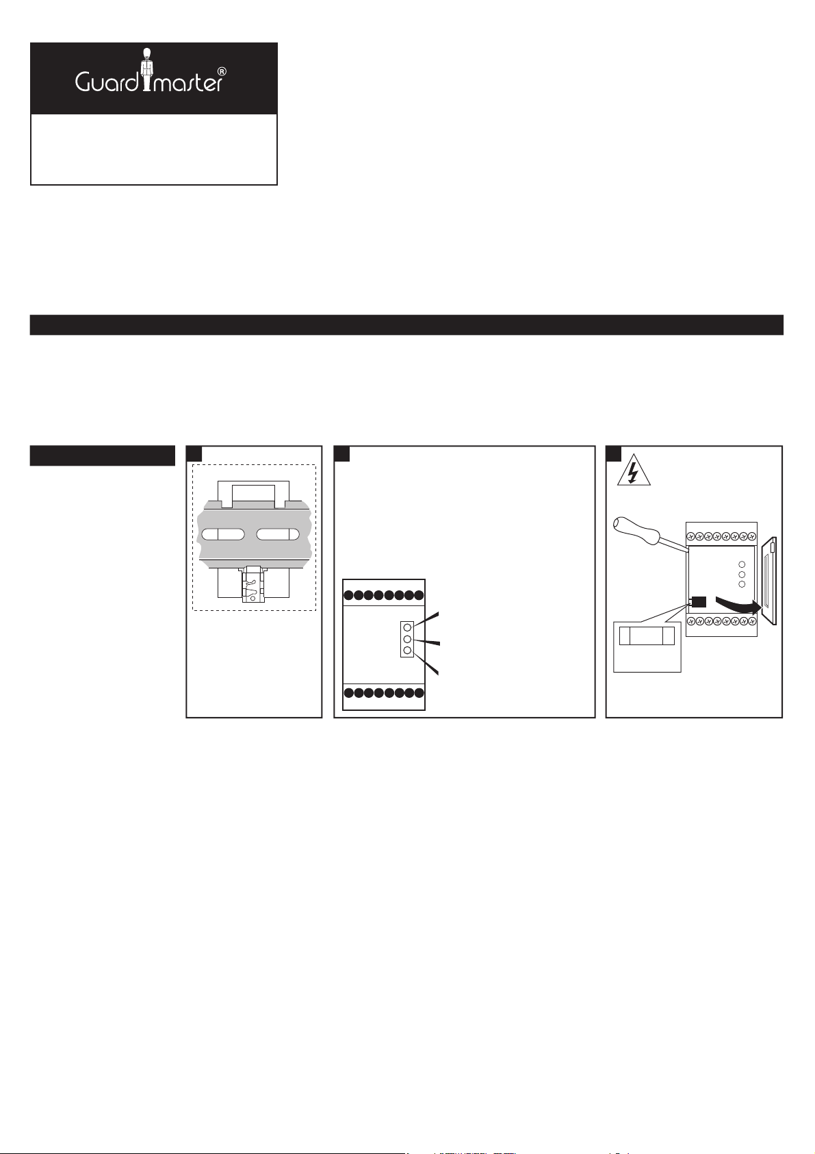
(e) Rückansicht / Vue arrière.
(f) Auf 35mm-Normschiene.
Montage sur rail DIN 35mm.
(g) In Gehäuse mit mind. IP 54 anbringen.
A monter dans coret minimum IP 54.
(h) Anschlüsse:
A1 & A2 = Versorgung 230 oder 110V AC
oder 24V AC/DC. (siehe Geräteseite)
S13 = Schließer Schalter 1.
S24 = Schließer Schalter 2.
S14 = Öner Schalter 2- EN 574 Cat IIIb
S23 = Öner Schalter 1- EN 574 Cat IIIb
X2 = Schützüberwachung.
X1 = Gemeinsamer Pol (siehe Schritt 4).
41 x 42 = Hilfsausgang (Ö).
13 x 14 = Sicherheitsaugang 1 (S).
23 x 24 = Sicherheitsaugang 2 (S).
33 x 34 = Sicherheitsaugang 3 (S).
Connexions:
A1 & A2 = alimentation 230 ou 110V AC ou
24V AC/DC (voir ci-contre pour
plus de détails)
S13 = entrée circuit 1 (N/O)
S24 = entrée circuit 2 (N/O)
S14 = entrée circuit 2 - EN 574 Cat IIIb (N/C)
S23 = entrée circuit 1 - EN 574 Cat IIIb (N/C)
X2 = contrôle de sortie (contacteur)
X1 = commum (voir plan 4)
41 x 42 = sortie auxiliaire (N/C)
13 x 14 = sortie de sécurité 1 (N/O)
23 x 24 = sortie de sécurité 2 (N/O)
33 x 34 = sortie de sécurité 3 (N/O)
(i) LED Anzeigen:
POWER (ROT) - Leuchtet, wenn
Spannung anliegt.
K1 (GRÜN) - Leuchtet, wennn interner
Kontakt K1.
K2 (GRÜN) - Leuchtet, wenn interner
Kontakt K2 geschlossen.
Indication LED:
ALIMENTATION(ROUGE)- illuminée quand
l'unité est sous tension.
K1 (VERT)- illuminé quand les contacts
internes de K1 sont fermés.
K2 (VERT)- illuminé quand les contacts
internes de K2 sont fermés.
1 32
(f) Mount on 35mm DIN rail.
(g) Mount in enclosure
to a min of IP 54.
(j) Vor Abnehmen des Deckels
Spannung abschalten.
Isoler les alimentations.
(k) Austauschen Sicherung.
Fusible remplaçable.
(e) Back View
Einbauanleitung
Die Montage ist entsprechend den folgenden Schritten durchzuführen.
ANMERKUNG: Falls das Gerät für Sicherheitsaufgaben eingesetzt
DIESE ANLEITUNG AUFBEWAHREN
werden soll, muß die Tastereinheit den Anforderungen
von EN 574 entsprechen.
(h) Connections
A1 & A2 = Supply 230 or 110V AC
or 24V AC/DC. (see side for details)
S13 = N/O from switch 1.
S24 = N/O from switch 2.
S14 = N/C (from switch 2- EN 574 Cat IIIb).
S23 = N/C (from switch 1- EN 574 Cat IIIb).
A1 S13 S24 X1
A2 S14 S23 X2
23 331341
(i) LED Indication
POWER (RED) - Illuminated when
there is power to the unit.
K1 (GREEN) - Illuminated when
internal contacts K1 are closed.
K2 (GREEN) - Illuminated when
internal contacts K2 are closed.
24 341442
X2 = Outputs (contactor) monitoring.
X1 = Common (see step 4).
41 x 42 = Auxiliary output (N/C).
13 x 14 = Safety output 1 (N/O).
23 x 24 = Safety output 2 (N/O).
33 x 34 = Safety output 3 (N/O).
Notice D'installation
GARDEZ EN MEMOIRE CES INSTRUCTIONS
L'installation dev ra suivre les étapes suivantes et sera
eectuée par du personnel compét ent et qualié.
NOTE: Si le système est utilisé dans un but de sécurité,
les boutons doivent être conformes aux
exigences se la norme en 574
(j) Isolate power before removing cover
500 mAT
(k)
Fuse replacement
Page 2
Deutsch / Français
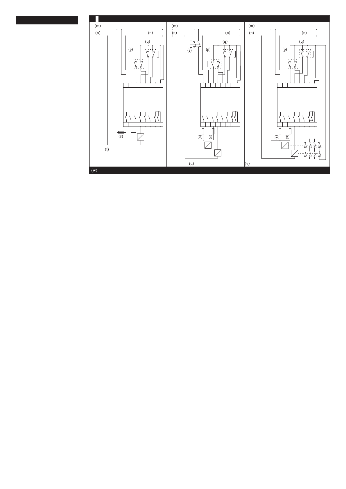
(m)Eingangsspanung / tension d'entrée.
(n) Versorgung / Alimentation.
(p) Schalter 1 / interrupteur 1.
(q) Schalter 2 / interrupteur 2.
(r) NOT-AUS / arrêt d'urgence.
(s) Sicherung / fusible.
(t) 2-Hand-Einheit mit einem Schütz.
Contrôleur à deux mains avec
contacteur unique.
(u) 2-Hand-Einheit mit NOT-AUS.
Contrôleur à deux mains avec
arrêt d'urgence.
(v) 2-Hand-Einheit mit zwei Schützen
und Schützüber wachung.
Contrôleur à deux mains avec deux
contacteurs et contrôle des contacteurs.
(w)ANMERKUNG: Bevor Maschine in
Betrieb genommen wird, durch Betätigen
nur eines tasters sicherstellen, daß die
Maschine nicht anläuft. Alle Ausgänge
sind durch eine externe Sicherung
zu schü tzen.
NOTE:avant de faire fonctionner la
machine en mode normal, vérier que les
sorties ne sont pas actionnées en actionnant
un seul bouton de sécurité. Toutes les sorties
doivent être protégées par un fusible externe.
4b
WIRING EXAMPLES CONFORMING TO EN 574 CAT. IIIb
230V AC, 110V AC or 24V AC/DC Input Voltage
SupplySupply Supply Supply Supply Supply
Switch
2
Switch
1
A1
A2
S13 S14 S23 S24 X1 X2
SUPPLY SWITCH1SWITCH2RESET
MSR7R
13
14 23 24 33 34 41 42
Fuse
2 Hand controller with single contactor.
NOTE: Before assuming normal machine operation, check that the outputs are not operated by operating just one of the safety but tons. All outputs must be protected by an external fuse.
K1
230V AC, 110V AC or 24V AC/DC Input Voltage
Switch
E-Stop
Switch
1
A1
A2
S13 S14 S23 S24 X1 X2
SUPPLY SWITCH1SWITCH2RESET
MSR7R
13
14 23 24 33 34 41 42
Fuse
Fuse
K1
K2
2 Hand controller with E-Stop.
230V AC, 110V AC or 24V AC/DC Input Voltage
2
Switch
1
A1
A2
S13 S14 S23 S24 X1 X2
SUPPLY SWITCH1SWITCH2RESET
MSR7R
13
14 23 24 33 34 41 42
Fuse
Fuse
K1
2 Hand controller with 2 contacts and contactor monitoring.
Switch
K2
2
K1
K2
Page 3

Deutsch / Français
(x) Montage auf 35mm-Normschiene.
Montage sur rail DIN 35mm.
120 45.5
(x)
35mm DIN Rail Mounting
73
(y) Technical Specications
Conforming to Standards
Power Supply
Power consumption
X1-X2 Contactor monitor loop
Safety inputs
Internal fuse
Relay outputs
Utilisation cat. (AC)
Max. switched DC current / volts
Min. switched current / volts
Max. output fuse
Indication LED 1
LED 2
LED 3
Drop out time
Impulse withstand voltage
Operating temperature
Contamination level
Humidity
Enclosure protection
Terminal isolation
Max. conducter size
Terminals
Housing
Weight
Material and colour
Installation group
Fixing details
EN 574 Type IIIB,
EN 60204, BS EN 292.
24V AC/DC, 110V AC or 230V AC.
<4 VA.
N/C contactor loop.
Connections for 2 buttons (1N/O-1N/C).
500mA replaceable supply fuse.
3 N/O + 1 N/C (TUV approved).
250V AC / 4A / 1000VA at COSØ = 1.
30V DC / 2A / 60W.
10mA / 10V.
5A Quick acting.
Red = Power on
Green 1 = RL1 closed
Green 2 = RL2 closed
50 mS.
2500V.
-10°C to +55°C.
III.
90% RH at +55°C.
IP40.
IP20.
2
stranded with sleeves
1 x 2.5mm
stripped 8mm. 1 x 4mm
Plus-minus terminal screws M3.5 box
terminal with wire protection.
16 Way, D=120, H= 73, W=45.5mm.
360g.
Red polycarbonate.
C in accordance with VDE 0110.
35mm DIN rail.
2
solid conducter.
Entspricht den Normen
Gehäuse
Gehäusematerial
Montage
Schutzklasse
Anschlüsse
Leiterbefestigung
Schutzart
Feuchtigkeit
LED-Anzeigen
Betriebsspannung
Leistungsverbrauch
Interne Sicherung
Eingang
X1/X2
Freigabeausgänge
Zusatzausgang
Gebrauchskategorie Ausgänge
Minimaler Strom/Spannung
Max. Absicherung der Ausgänge
Abfallzeit
Überspannun gskategorie
Verschmutzungsgrad
Bet riebstemperatur
Litze
Conforme aux normes
Alimentation
Consommation
Bornes X1-X2
Entées de sécurité
Fusible interne
Contacts de sortie
Pouvoir de coupure max
Charge/courant/tension
Pouvoir de coupure mini
Fusible de sortie externe
Lampes
Temps de réponse
Tension d'isolement
Température ambiante
Niveau de contamination
Humidité
IP Boîtier
IP Bornier
Choix des câbles
Bornes
Poids
Matériaux et couleur
Boîtier
Groupe d'installation
Fixation
EN 574 lllB,
EN 60204/DIN VDE 0113
EN 292
Schnellbefestigung auf Normschiene,
16 Klemmen, 73 x 45,5 x 120 mm
Polycarbonat, rot
35 mm DIN-Hutschiene
Entfällt (Einbaugerät nach E-DIN 50178)
Schraubanschlüsse für 2 x 2,5 mm
mit Hülse; max. Länge der abisolierten
Anschlußleitungen 8 mm;
2
massiv
1 x 4 mm
Plus-Minus-Klemmenschrauben M3,5;
Kastenklemme mit selbstabhebendem
Drahtschutz
Anschlüsse IP 20, Gehäuse IP 40
Max. 90 % bei +55 °C
1: Rot = Betriebsspannung (Power)
2: Grün = Ausgang K1
3: Grün = Ausgang K2
24V AC/DC, 110V AC oder 230V AC
< 4 VA
500 mAT (austauschbar)
2 Taster mit je 1Ö + 1S
Schütz-Hilfskontakt
3 Schließer
1 Öner; nur für Meldezwecke
AC-15: 4 A/ 250V AC; DC-13: 2 A/30V DC
10 mA/10 V
5 A .
Typ. 50 ms
ll nach DIN VDE 0110
3 nach DIN VDE 0110
-10°C bis +55°C
2
Specications TechniquesTechnische Daten
EN574 type lllB,
EN60204, BS EN292
24V AC/DC, 110V AC ou 230V AC
<4VA
Boucle de retour pour contrôle et
réarmement (contacte N/C)
connections pour 2 boutons 1N/O & 1N/O
500mA remplaçable
3 N/O + 1N/C instantanés approuvés TUV
4A/250V AC/1000V A à COSØ=1
2A/30VDC/60W
10 mA/10V
Max 5A à fusion rapide
LED 1: Rouge: Alimentation ON
LED 2: Verte 1: RL1 fermé
LED 3: Verte 2: RL2 fermé
50mS pour les sorties
2500V
-10°C à +55°C
III
90% de RH à +50°C
IP 40 DIN 0470
IP 40 DIN 0470
2
souple avec cosses 8mm,
1 x 2.5mm
2
rigide
1 x 4mm
Vis M3.5 Plus/Moins avec protection câble
360 grs
Polycarbonate rouge
16 voies P=120mm, H=73mm, L=45.5mm
C en accord VDE 0110
Rail Din 35 mm
(z) USE
The MSR7R checks for single faults of dual channel safety circuits
when the actuators are operated. The actuators must be pressed
simultaneously (within 0.5secs) to close the MSR7R output contacts.
The MSR7R should be used with a 2 hand control actuator which
complies with the requirements of EN 574.
BETRIEB
Der MSR7R überwacht auf einzelne Fehler in zweikanaligen
Sicherheitskreisen, wenn Schaltgeräte betätigt werden. Die
Schaltgeräte müssen gleichzeitig gedrückt werden (innerhalb 0,5s),
um ein Freigabesignal auszulösen. Der MSR7R ist mit 2-HandSchaltgeräten zu verwenden, die den Anforderungen von EN 574
entsprechen.
UTILISATION
Le Monotaur MSR7R contrôle les pannes simples sur des circuits de
sécurité en service quand les boutons poussoirs sont actionnés. Les
bouton poussoirs doivent être enfoncés simultanément (en mois de
0.5 secs) pour fermer les circuits de MSR7R. Le MSR7R doit être
utilisé avec un pupitre à deux mains qui satisfait aux exigences de la
norme EN 574.
Page 4

(a1) MAINTENANCE
Every Week
Press each switch or push button individually in turn, check that the
MSR7R outputs do not close. Press both switchs simultaneously
(within 0.5secs), the MSR7R outputs should close, release one
switch, Check that the MSR7R outputs open immediatly and that
they cannot be closed again until both switchs have been released
and then pressed simultaneously. During these tests, check that the
LED's are operating correctly.
At least every 6 months
Isolate all power! Check for correct terminal connections and check
wiring for signs of damage.
WARTUNG
Jede Woche
Jeden Taster einzeln drücken und prüfen, daß kein Ausgangssig nal
ausgelöst wird. Dan beide Taster gleichzeitig drücken (innerhalb
0,5s), und das Gerät muß schalten. einen Taster loslassen und
prüfen, ob das Gerät sofort abschaltet und nicht wieder einschalten
kann, bevor beide Taster losgelassen und dann gleichzeitig gedrückt
werden. Bei diesen Test prüfen, ob die LED's korrekt arbeiten.
Wenigstens alle 6 Monate
Spannung abschalten. Anschlüsse und Verdrahtung auf Schäden
überprüfen.
MAINTENANCE
Chaque semaine
Presser chaque interrupteur et chaque bouton poussoir tour en
vériant que les sorties du MSR7R ne se ferment pas. Enfoncer
simultanément les deux interrupteurs (en moins de 0.5 secs), les
sorties du MSR7R doivent se fermer, relâcher un des interrupteurs
vérier que les sorties du MSR 7R s'ouvrent instantanément et
qu'elles ne peuvent pas être de nouveau fermés sans que les deux
interrupteurs aient été relâchés et réenclenchés simultanément.
Pendant ces testes vérier que les diodes LED fonctionnent
correctement.
Au moins une fois tous les 6 mois
Couper toute alimentation! Vérier l'état des connexions sur les
broches du MSR7R et l'état du câblage.
(b1) REPAIR
If there is any malfunction or damage, no attempts should be made
to repair it. The control unit should be replaced before machine
operation is allowed.
DO NOT DISMANTLE THE UNIT.
(c1) TROUBLESHOOTING
LED Status
Symptom
Output contacts fail to close
Output contacts fail to close
Output contacts fail to close
Output contacts fail to close
Power K1 K2
OFF OFF OFF
ON ON OFF
ON OFF ON
ON OFF OFF
LED Status
Symptom
Ausgang schließt nicht
Ausgang schließt nicht
Ausgang schließt nicht
Ausgang schließt nicht
Power K1 K2
Aus Aus Aus
An An Aus
An Aus An
An Aus Aus
REPARATUR
Falls Fehlfunktionen oder Schäden auftreten, keine Versuche zur
Reparatur unternehmen. Der Schalter muß ersetzt werden, bevor die
Maschine wieder gestartet wird.
GERÄT DARF NIEMALS GEÖFFNEN WERDEN!
FEHLERSUCHE
Cause
Fault on power supply to Minotaur.
Fault on one switch or input circuit.
Fault on one switch or input circuit.
Fault on input circuit.
Ursache
Fehler an Spannungsversorgung
Fehler am Eingangskreis
Fehler am Eingangskreis
Fehler am Eingangskreis
REPARATION
En cas de dysfonctionnement ou de dégradation, ne pas attendre
pour réparer. L'interrupteur doit être remplacé immédiatement avant
le démarrage de la machine.
DANS TOUS LES CAS, NE DISLOQUEZ PAS L'APPAREIL.
LOCALISATION DE PANNE
Symptôme
le contact de sortie ne se ferme pas
le contact de sortie ne se ferme pas
le contact de sortie ne se ferme pas
le contact de sortie ne se ferme pas
Etat de diodes
alim K1 K2
OFF OFF OFF
ON ON OFF
ON OFF ON
ON OFF OFF
Cause
panne d'alimentation du Minotaur
panne d'un interrupteur ou du circuit d'entrée
panne d'un interrupteur ou du circuit d'entrée
panne sur le circuit d'entrée
R
Drg No: 23877 Issue No: 5
Change No: 14213
 Loading...