

Page 1

MSR312P Configurable Monitoring Safety
Relay with DeviceNet™ Communications
USER MANUAL
440R
Page 2
Important User Information
ATTENTION
IMPORTANT
Because of the variety of uses for the products described in this publication, those responsible for the application and use of this
control equipment must satisfy themselves that all necessary steps have been taken to assure that each application and use
meets all performance and safety requirements, including any applicable laws, regulations, codes and standards.
The illustrations, charts, sample programs and layout examples shown in this guide are intended solely for purposes of
example. Since there are many variables and requirements associated with any particular installation, Rockwell Automation
does not assume responsibility or liability (to include intellectual property liability) for actual use based upon the examples
shown in this publication.
Rockwell Automation Publication SGI-1.1, Safety Guidelines for the Application, Installation and Maintenance of Solid-State
Control (available from your local Rockwell Automation office), describes some important differences between solid-state
equipment and electromechanical devices that should be taken into consideration when applying products such as those
described in this publication.
Reproduction of the contents of this copyrighted publication, in whole or part, without written permission of Rockwell
Automation, is prohibited.
Definition of Symbols
Identifies information about practices or circumstances that
can lead to personal injury or death, property damage, or
economic loss. Attentions help you identify a hazard, avoid a
hazard, and recognize the consequences.
Throughout this manual we use notes to make you aware of safety considerations:
Attention statements help you to:
• identify a hazard
• avoid a hazard
• recognize the consequences
Identifies information about practices or circumstances that
can lead to personal injury or death, property damage, or
economic loss. Attentions help you identify a hazard, avoid a
hazard, and recognize the consequences.
Allen-Bradley, RSNetWorx, DeviceLogix, PLC, and SLC are registered trademarks of Rockwell Automation.
DeviceNet is a trademark of the Open DeviceNet Vendor Association (ODVA).
MSR312-UM001B-EN-P
Page 3
Configurable Monitoring Safety Relay with DeviceNet™ Communications
ATTENTION
ATTENTION
European Communities (EC) Directive Compliance
European Communities (EC) Directive Compliance
This product has the CE mark and is approved for installation within the European Union and EEA regions. It has been designed
and tested to meet the following directives.
EMC Directive
This product is tested to meet the Council Directive 89/336/EC Electromagnetic Compatibility (EMC) by applying the following
standards, in whole or in part, documented in a technical construction file:
• EN 50081-2 EMC — Generic Emission Standard, Part 2 — Industrial Environment
• EN 50082-2 EMC — Generic Immunity Standard, Part 2 — Industrial Environment
This product is intended for use in an industrial environment.
Low Voltage Directive
This product is not required to meet Council Directive 73/23/EEC Low Voltage, as it is designed for use with a voltage rating
below 50V for alternating current and below 75V for direct current. The requirements of EN 60947-5-1:1997 Low-Voltage
Switchgear and Controlgear, Part 5 — Control Circuit Devices, have been applied.
Preface
Read this manual in its entirety before installing, operating, servicing, or configuring the MSR312P
Safety Relay with DeviceNet communications.
The purpose of this manual is to provide you with the necessary information to apply the MSR312P Safety Relay using
DeviceNet™ with DeviceLogix Component Technology. Described in this manual are methods for installing, configuring, and
troubleshooting the MSR312P DeviceNet.
Intended Audience
This manual is intended for qualified personnel responsible for the setup and service of these devices. You must have previous
experience with and a basic understanding of communications terminology, configuration procedures, required equipment, and
safety precautions.
You should understand the DeviceNet network operations, including how slave devices operate on the network and
communicate with a DeviceNet master.
You should be familiar with the use of the RSNetWorx for DeviceNet Software (Cat. No. 9357-DNETL3) for network
configuration. This software package is referred to often in this manual.
Read the DeviceNet Cable System Planning and Installation Manual, Publication 1485-6.7.1, in its
entirety before planning and installing a DeviceNet System. If the network is not installed
according to this document, unexpected operation and intermittent failures can occur.
If this manual is not available, consult your local Rockwell Automation Authorized Distributor or
Sales Office to request a copy. Copies may also be ordered from the Rockwell Automation
Bookstore. The bookstore can be contacted via the Internet from the Rockwell Automation home
page at http://www.rockwellautomation.com.
Only personnel familiar with DeviceNet devices and associated equipment should plan or
implement the installation, startup, configuration, and subsequent maintenance of the MSR312P
Configurable monitoring Safety Relay. Failure to comply may result in personal injury and/ or
equipment damage.
Voca bula ry
In this manual we refer to the MSR312P Safety Relay with DeviceNet Communications with DeviceLogix Component
Technology as the “MSR312P.”
MSR312-UM001B-EN-P 3
Page 4

Configurable Monitoring Safety Relay with DeviceNet™ Communications
Preface
Related Publications
Publication Title Publication Number
DeviceNet™ Cable System Planning and Installation Manual DN-6.7.2
ControlLogix™ DeviceNet Interface Module User Manual 1756-6.5.19
DeviceNet Media Catalog Guide 1485-CG001A-EN-P
Online Information
EDS Files: EDS files are available for downloading at http://www.ab.com/networks/eds.
Manuals Online: Manuals are available for order or download at http://www.theautomationbookstore.com
This manual gives an overview of the MSR312P and describes how to configure, install, operate, and troubleshoot the device on
the DeviceNet network.
4 MSR312-UM001B-EN-P
Page 5

Configurable Monitoring Safety Relay with DeviceNet™ Communications
Table of Contents
Table of Contents
Important User Information. . . . . . . . . . . . . . . . . . . . . . . . . . . . . . . . . . . . . . . . . . . . . . . . . . . . . . . . . . . . . . . . . . . . . . . . . . . . . . 2
European Communities (EC) Directive Compliance . . . . . . . . . . . . . . . . . . . . . . . . . . . . . . . . . . . . . . . . . . . . . . . . . . . . . . . . . . . 3
EMC Directive . . . . . . . . . . . . . . . . . . . . . . . . . . . . . . . . . . . . . . . . . . . . . . . . . . . . . . . . . . . . . . . . . . . . . . . . . . . . . . . . . . . . . . . . . . 3
Low Voltage Directive . . . . . . . . . . . . . . . . . . . . . . . . . . . . . . . . . . . . . . . . . . . . . . . . . . . . . . . . . . . . . . . . . . . . . . . . . . . . . . . . . . . . 3
Preface . . . . . . . . . . . . . . . . . . . . . . . . . . . . . . . . . . . . . . . . . . . . . . . . . . . . . . . . . . . . . . . . . . . . . . . . . . . . . . . . . . . . . . . . . . . . . 3
Intended Audience. . . . . . . . . . . . . . . . . . . . . . . . . . . . . . . . . . . . . . . . . . . . . . . . . . . . . . . . . . . . . . . . . . . . . . . . . . . . . . . . . . . . . . . 3
Vocabulary . . . . . . . . . . . . . . . . . . . . . . . . . . . . . . . . . . . . . . . . . . . . . . . . . . . . . . . . . . . . . . . . . . . . . . . . . . . . . . . . . . . . . . . . . . . . . 3
Related Publications . . . . . . . . . . . . . . . . . . . . . . . . . . . . . . . . . . . . . . . . . . . . . . . . . . . . . . . . . . . . . . . . . . . . . . . . . . . . . . . . . . . . . 4
Online Information . . . . . . . . . . . . . . . . . . . . . . . . . . . . . . . . . . . . . . . . . . . . . . . . . . . . . . . . . . . . . . . . . . . . . . . . . . . . . . . . . . . . . . . 4
Chapter 1: Overview of the MSR312P DeviceNet Base Module . . . . . . . . . . . . . . . . . . . . . . . . . . . . . . . . . . . . . . . . . . . . . . . . . 6
Description. . . . . . . . . . . . . . . . . . . . . . . . . . . . . . . . . . . . . . . . . . . . . . . . . . . . . . . . . . . . . . . . . . . . . . . . . . . . . . . . . . . . . . . . . . . . . 6
Rotary Switches. . . . . . . . . . . . . . . . . . . . . . . . . . . . . . . . . . . . . . . . . . . . . . . . . . . . . . . . . . . . . . . . . . . . . . . . . . . . . . . . . . . . . . . . . 6
Node Address Configuration . . . . . . . . . . . . . . . . . . . . . . . . . . . . . . . . . . . . . . . . . . . . . . . . . . . . . . . . . . . . . . . . . . . . . . . . . . . . . . . 6
Data Rate Configuration . . . . . . . . . . . . . . . . . . . . . . . . . . . . . . . . . . . . . . . . . . . . . . . . . . . . . . . . . . . . . . . . . . . . . . . . . . . . . . . . . . 6
DeviceNet Connection . . . . . . . . . . . . . . . . . . . . . . . . . . . . . . . . . . . . . . . . . . . . . . . . . . . . . . . . . . . . . . . . . . . . . . . . . . . . . . . . . . . . 6
Parameter Configuration . . . . . . . . . . . . . . . . . . . . . . . . . . . . . . . . . . . . . . . . . . . . . . . . . . . . . . . . . . . . . . . . . . . . . . . . . . . . . . . . . . 7
Chapter 2: Troubleshooting and Maintenance . . . . . . . . . . . . . . . . . . . . . . . . . . . . . . . . . . . . . . . . . . . . . . . . . . . . . . . . . . . . . . . 8
Using the Status LED. . . . . . . . . . . . . . . . . . . . . . . . . . . . . . . . . . . . . . . . . . . . . . . . . . . . . . . . . . . . . . . . . . . . . . . . . . . . . . . . . . . . . 8
Chapter 2: Device Parameters . . . . . . . . . . . . . . . . . . . . . . . . . . . . . . . . . . . . . . . . . . . . . . . . . . . . . . . . . . . . . . . . . . . . . . . . . . . 9
Parameter 1 to 20—Input Values. . . . . . . . . . . . . . . . . . . . . . . . . . . . . . . . . . . . . . . . . . . . . . . . . . . . . . . . . . . . . . . . . . . . . . . . . . . . 9
Parameter 21 to 23—Input Module Values . . . . . . . . . . . . . . . . . . . . . . . . . . . . . . . . . . . . . . . . . . . . . . . . . . . . . . . . . . . . . . . . . . . . 9
Parameters 24 to 26—Simultaneity Errors . . . . . . . . . . . . . . . . . . . . . . . . . . . . . . . . . . . . . . . . . . . . . . . . . . . . . . . . . . . . . . . . . . . . 9
Parameters 27 to 29—Simultaneity Enabled . . . . . . . . . . . . . . . . . . . . . . . . . . . . . . . . . . . . . . . . . . . . . . . . . . . . . . . . . . . . . . . . . . . 9
Parameters 30 to 32—Group Status . . . . . . . . . . . . . . . . . . . . . . . . . . . . . . . . . . . . . . . . . . . . . . . . . . . . . . . . . . . . . . . . . . . . . . . . 10
Parameters 33 to 35—Feedback (Monitoring) Loop Status . . . . . . . . . . . . . . . . . . . . . . . . . . . . . . . . . . . . . . . . . . . . . . . . . . . . . . 10
Parameters 36 to 38—Group State . . . . . . . . . . . . . . . . . . . . . . . . . . . . . . . . . . . . . . . . . . . . . . . . . . . . . . . . . . . . . . . . . . . . . . . . . 10
Parameters 39—Group Reset State . . . . . . . . . . . . . . . . . . . . . . . . . . . . . . . . . . . . . . . . . . . . . . . . . . . . . . . . . . . . . . . . . . . . . . . . 10
Parameters 40-49—Function Settings . . . . . . . . . . . . . . . . . . . . . . . . . . . . . . . . . . . . . . . . . . . . . . . . . . . . . . . . . . . . . . . . . . . . . . 11
Parameters 50-59—Nonvolatile (EEPROM) Function Settings . . . . . . . . . . . . . . . . . . . . . . . . . . . . . . . . . . . . . . . . . . . . . . . . . . . . 11
Parameters 60-69—Group Switch Settings . . . . . . . . . . . . . . . . . . . . . . . . . . . . . . . . . . . . . . . . . . . . . . . . . . . . . . . . . . . . . . . . . . 12
Parameters 70-79—Group Switch Nonvolatile (EEPROM) Settings . . . . . . . . . . . . . . . . . . . . . . . . . . . . . . . . . . . . . . . . . . . . . . . . 12
Parameters 80—System Faults . . . . . . . . . . . . . . . . . . . . . . . . . . . . . . . . . . . . . . . . . . . . . . . . . . . . . . . . . . . . . . . . . . . . . . . . . . . . 13
Parameters 81—Any System Faults . . . . . . . . . . . . . . . . . . . . . . . . . . . . . . . . . . . . . . . . . . . . . . . . . . . . . . . . . . . . . . . . . . . . . . . . 13
Parameters 82—Muting Lamp Module Faults . . . . . . . . . . . . . . . . . . . . . . . . . . . . . . . . . . . . . . . . . . . . . . . . . . . . . . . . . . . . . . . . . 13
Parameters 83—Y34 Output Value . . . . . . . . . . . . . . . . . . . . . . . . . . . . . . . . . . . . . . . . . . . . . . . . . . . . . . . . . . . . . . . . . . . . . . . . . 13
Parameters 84—Y34 Output Status . . . . . . . . . . . . . . . . . . . . . . . . . . . . . . . . . . . . . . . . . . . . . . . . . . . . . . . . . . . . . . . . . . . . . . . . 13
Parameters 85—Y34 Output Fault Action . . . . . . . . . . . . . . . . . . . . . . . . . . . . . . . . . . . . . . . . . . . . . . . . . . . . . . . . . . . . . . . . . . . . 13
Parameters 86—Y34 Output Fault Value. . . . . . . . . . . . . . . . . . . . . . . . . . . . . . . . . . . . . . . . . . . . . . . . . . . . . . . . . . . . . . . . . . . . . 13
Parameter 87—Y34 Output Mode Attribute . . . . . . . . . . . . . . . . . . . . . . . . . . . . . . . . . . . . . . . . . . . . . . . . . . . . . . . . . . . . . . . . . . 14
Parameter 88—Y34 Output Idle Value. . . . . . . . . . . . . . . . . . . . . . . . . . . . . . . . . . . . . . . . . . . . . . . . . . . . . . . . . . . . . . . . . . . . . . . 14
Parameter 90—Autobaud . . . . . . . . . . . . . . . . . . . . . . . . . . . . . . . . . . . . . . . . . . . . . . . . . . . . . . . . . . . . . . . . . . . . . . . . . . . . . . . . 14
Parameter 91—Baud Rate Switch Change . . . . . . . . . . . . . . . . . . . . . . . . . . . . . . . . . . . . . . . . . . . . . . . . . . . . . . . . . . . . . . . . . . . 14
Parameter 92—Baud Rate Switch Value . . . . . . . . . . . . . . . . . . . . . . . . . . . . . . . . . . . . . . . . . . . . . . . . . . . . . . . . . . . . . . . . . . . . . 14
Parameter 93—MAC ID Switch Change . . . . . . . . . . . . . . . . . . . . . . . . . . . . . . . . . . . . . . . . . . . . . . . . . . . . . . . . . . . . . . . . . . . . . 14
Parameter 94—MAC ID Switch Value . . . . . . . . . . . . . . . . . . . . . . . . . . . . . . . . . . . . . . . . . . . . . . . . . . . . . . . . . . . . . . . . . . . . . . . 14
Parameter 95—Configuration Consistency Value . . . . . . . . . . . . . . . . . . . . . . . . . . . . . . . . . . . . . . . . . . . . . . . . . . . . . . . . . . . . . . 15
Parameter 96—Serial Number . . . . . . . . . . . . . . . . . . . . . . . . . . . . . . . . . . . . . . . . . . . . . . . . . . . . . . . . . . . . . . . . . . . . . . . . . . . . . 15
Parameter 97—Runtime . . . . . . . . . . . . . . . . . . . . . . . . . . . . . . . . . . . . . . . . . . . . . . . . . . . . . . . . . . . . . . . . . . . . . . . . . . . . . . . . . 15
Parameter 98—Power-up Count . . . . . . . . . . . . . . . . . . . . . . . . . . . . . . . . . . . . . . . . . . . . . . . . . . . . . . . . . . . . . . . . . . . . . . . . . . . 15
Parameter 99—Voltage . . . . . . . . . . . . . . . . . . . . . . . . . . . . . . . . . . . . . . . . . . . . . . . . . . . . . . . . . . . . . . . . . . . . . . . . . . . . . . . . . . 15
Parameter 100—Number of Input Modules. . . . . . . . . . . . . . . . . . . . . . . . . . . . . . . . . . . . . . . . . . . . . . . . . . . . . . . . . . . . . . . . . . . 15
Parameter 101—Number of Input Modules in Nonvolatile Memory (EEPROM) . . . . . . . . . . . . . . . . . . . . . . . . . . . . . . . . . . . . . . . 15
Parameter 102—MSR Processor Version Number . . . . . . . . . . . . . . . . . . . . . . . . . . . . . . . . . . . . . . . . . . . . . . . . . . . . . . . . . . . . . 15
Parameter 103—105 . . . . . . . . . . . . . . . . . . . . . . . . . . . . . . . . . . . . . . . . . . . . . . . . . . . . . . . . . . . . . . . . . . . . . . . . . . . . . . . . . . . . 15
Chapter 3: Quick Start Guide . . . . . . . . . . . . . . . . . . . . . . . . . . . . . . . . . . . . . . . . . . . . . . . . . . . . . . . . . . . . . . . . . . . . . . . . . . . 18
Chapter 4: Getting Online via RSNetWorx™ for DeviceNet™ . . . . . . . . . . . . . . . . . . . . . . . . . . . . . . . . . . . . . . . . . . . . . . . . . . 33
Chapter 5: Unregister the EDS file . . . . . . . . . . . . . . . . . . . . . . . . . . . . . . . . . . . . . . . . . . . . . . . . . . . . . . . . . . . . . . . . . . . . . . . 39
Chapter 6: Register the MSR312P EDS Device . . . . . . . . . . . . . . . . . . . . . . . . . . . . . . . . . . . . . . . . . . . . . . . . . . . . . . . . . . . . . 41
Chapter 7: Off-Line Node Recovery . . . . . . . . . . . . . . . . . . . . . . . . . . . . . . . . . . . . . . . . . . . . . . . . . . . . . . . . . . . . . . . . . . . . . . 44
Sample Recovery. . . . . . . . . . . . . . . . . . . . . . . . . . . . . . . . . . . . . . . . . . . . . . . . . . . . . . . . . . . . . . . . . . . . . . . . . . . . . . . . . . . . . . . 44
Chapter 8: DeviceNet Classes and Objects . . . . . . . . . . . . . . . . . . . . . . . . . . . . . . . . . . . . . . . . . . . . . . . . . . . . . . . . . . . . . . . . 48
Common Services . . . . . . . . . . . . . . . . . . . . . . . . . . . . . . . . . . . . . . . . . . . . . . . . . . . . . . . . . . . . . . . . . . . . . . . . . . . . . . . . . . . . . . 48
Identity Object . . . . . . . . . . . . . . . . . . . . . . . . . . . . . . . . . . . . . . . . . . . . . . . . . . . . . . . . . . . . . . . . . . . . . . . . . . . . . . . . . . . . . . . . . 48
Class Services . . . . . . . . . . . . . . . . . . . . . . . . . . . . . . . . . . . . . . . . . . . . . . . . . . . . . . . . . . . . . . . . . . . . . . . . . . . . . . . . . . . . . . . . . 48
Object Classes. . . . . . . . . . . . . . . . . . . . . . . . . . . . . . . . . . . . . . . . . . . . . . . . . . . . . . . . . . . . . . . . . . . . . . . . . . . . . . . . . . . . . . . . . 48
Class Code 0x0001: Identity Object . . . . . . . . . . . . . . . . . . . . . . . . . . . . . . . . . . . . . . . . . . . . . . . . . . . . . . . . . . . . . . . . . . . . . . . . 49
Class Code 0x0002: Message Router Object . . . . . . . . . . . . . . . . . . . . . . . . . . . . . . . . . . . . . . . . . . . . . . . . . . . . . . . . . . . . . . . . . 49
Class Code 0x0003: DeviceNet Object . . . . . . . . . . . . . . . . . . . . . . . . . . . . . . . . . . . . . . . . . . . . . . . . . . . . . . . . . . . . . . . . . . . . . . 49
Class Code 0x0004: Assembly Object . . . . . . . . . . . . . . . . . . . . . . . . . . . . . . . . . . . . . . . . . . . . . . . . . . . . . . . . . . . . . . . . . . . . . . 50
Class Code 0x0005: Connection Object . . . . . . . . . . . . . . . . . . . . . . . . . . . . . . . . . . . . . . . . . . . . . . . . . . . . . . . . . . . . . . . . . . . . . 52
Class Code 0x0008: Discrete Input Point Object . . . . . . . . . . . . . . . . . . . . . . . . . . . . . . . . . . . . . . . . . . . . . . . . . . . . . . . . . . . . . . 54
Class Code 0x0009: Discrete Output Point Object . . . . . . . . . . . . . . . . . . . . . . . . . . . . . . . . . . . . . . . . . . . . . . . . . . . . . . . . . . . . . 54
Class Code 0x001D: Discrete Input Group Object . . . . . . . . . . . . . . . . . . . . . . . . . . . . . . . . . . . . . . . . . . . . . . . . . . . . . . . . . . . . . 55
Class Code 0x002B: Acknowledge Handler Object . . . . . . . . . . . . . . . . . . . . . . . . . . . . . . . . . . . . . . . . . . . . . . . . . . . . . . . . . . . . 55
MSR312-UM001B-EN-P 5
Page 6
Configurable Monitoring Safety Relay with DeviceNet™ Communications
1
2
3
4
5
6
7
8
9
0
1
2
3
4
5
6
7
8
9
0
1
2
3
4
5
6
7
8
9
0
Chapter 1: Overview of the MSR312P DeviceNet Base Module
Chapter 1: Overview of the MSR312P DeviceNet Base Module
Description
The MSR312P offers DeviceNet connection for applications in which network communication is desired. All of the functionality
of the DeviceNet interface is contained within the enclosure. The base unit requires two 24V DC power sources. One is
connected to A1/A2 terminals to power the safety circuitry including all connected modules. The second is the DeviceNet power.
It’s recommended that they do not share the same source.
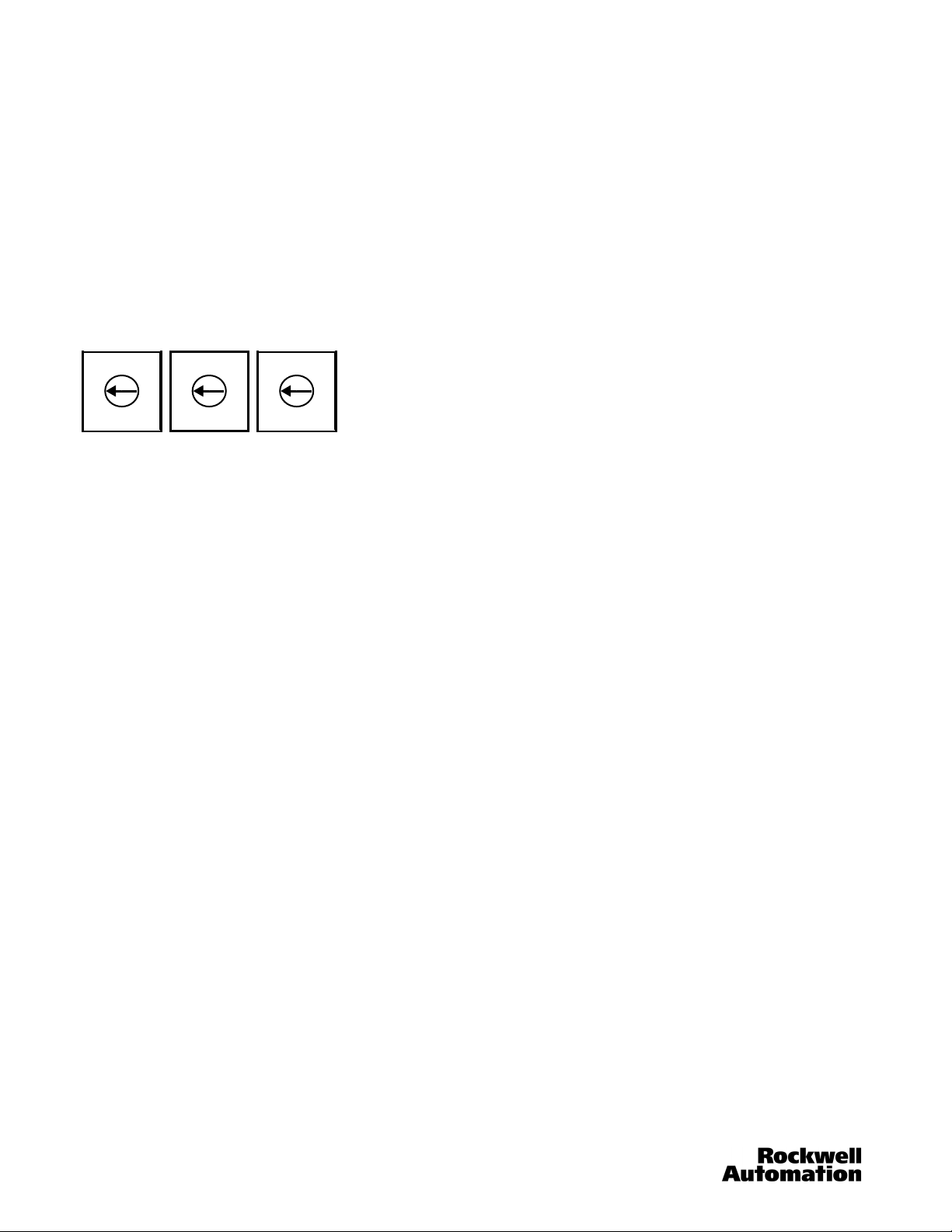
Rotary Switches
The MSR312P has three 10-position rotary switches for setting: DeviceNet baud rate and DeviceNet node address The
switches are located on the side of the enclosure. The switch settings and functions are shown below.
S1 S2 S3
MSB LSB
Node Address Baud Rate
MSB = Most Significant Byte
LSB = Least Significant Byte
Node Address Configuration
Rotary switches S1 and S2 are used to set the node address (0…63) of the MSR312P. The factory default is 63 on the switches.
If the node address is between 64…99, the MAC ID will be software settable. Rotate switches S1 and S2 to the desired address.
Data Rate Configuration
Rotary switch S3 sets the data rate at which the MSR312P communicates with the network. The factory default setting is
0…125 kb.
DeviceNet Connection
The MSR312P DeviceNet communications receives its power and communications through the DeviceNet Cable. A separate
power supply is required to power the MSR312P for its safety functions. This separate power supply must be connected to
terminals A1 and A2 of the MSR312P.
• CANH – White Wire
• CANL – Blue Wire
•V+ – Red Wire
• V- – Black Wire
• SHD – Shield
6 MSR312-UM001B-EN-P
Page 7
Configurable Monitoring Safety Relay with DeviceNet™ Communications
Chapter 1: Overview of the MSR312P DeviceNet Base Module
Parameter Configuration
For proper operation, the parameters of the MSR312P must be configured. There are 105 parameters in the MSR312P, but only
11 of them are configurable. The parameters can be configured by using RSNetWorx for DeviceNet. Open RSNetWorx and
double click on the MSR312P icon.
MSR312-UM001B-EN-P 7
Page 8

Configurable Monitoring Safety Relay with DeviceNet™ Communications
Chapter 2: Troubleshooting and Maintenance
Chapter 2: Troubleshooting and Maintenance
Using the Status LED
Function Status LED Group 1-2-3 LEDs
Power up / normal operation Continuous on: green —
Internal fault Continuous on: red —
Entering configuration mode 1 flash: red —
Input switch fault or reset switch closed during power up 2 flashes: red —
Configuration change during operation 3 flashes: red —
Current configuration not as stored on EEPROM 4 flashes: red —
At least one muting lamp and one reserve lamp defective 5 flashes: red —
Invalid switch settings of input modules 6 flashes: red —
Invalid reset configuration (Y41, Y42, S34 terminal jumpers) 7 flashes: red —
Input terminal block not (or improperly) plugged in 8 flashes: red —
Group output active — Continuous on: green
Group ready — Blinking: green
At least one input corresponding to the output group is faulty — Continuous on: red
A feedback (EDM) loop of the output group is open, or no input is assigned to the group — Off
Using the Mod/Net Status LED
Mod/Net State LED Indication
Not powered/not on-line Off Device is not on-line. Device has not completed the Dup MAC ID test. Device may not
be powered.
Device operational and online, connected
Device operational and online, not connected, or
device on-line and needs
commissioning
Minor fault and/or
connection time-out
Critical fault or critical link
failure
Communication faulted and
received an identify comm
fault request - long protocol
Solid green Device is operating in a normal condition and is on-line with connections in the
established state. For Group 2 only, the device is allocated to a master. For a UCMM
capable device it means that the device has one or more established connections.
Flashing green Device is on-line with no connections in the established state. Device has passed the
Dup MAC ID test, is on-line, but has no established connections to other nodes. For a
Group 2 Only device, the device is not allocated to a master. For a UCMM capable
device it means that the device has no established connections. Configuration
missing, incomplete or incorrect.
Flashing red Recoverable fault and/or one or more I/O connections are in the timed-out state.
Solid red Device has an unrecoverable fault and may need replacing. Device has detected an
Flashing red and
green
Recoverable faults include:
• Failed Power Supply power-up test.
• Faulted 24V DC, Out2, Out3.
error that has rendered it incapable of communication on the network (Dup MAC
failure or Bus Off).
A specific communcation faulted device. the device has detected a network access
error and is in the communcation faulted state. The device has subsequently received
and accepted an identify communcation faulted request - long protocol message.
8 MSR312-UM001B-EN-P
Page 9

Configurable Monitoring Safety Relay with DeviceNet™ Communications
Chapter 2: Device Parameters
Chapter 2: Device Parameters
Parameters 1…20—Input Values (read only)
Input 1a Value - Input 10b Value
The MSR312P supports up to 10 inputs modules to its input side. Each input module has two independent input connections.
These are shown as parameters Input 1a Value (the top wiring connection of the module) and Input 1b Value (the bottom
connection for input module 1). The input values can be either ON or OFF. Input values not used will show an OFF value.
A value of ‘ON’ indicates that the input is active. A device is connected properly and the input LED on the front of the module is
green.
A value of 'OFF' indicates that the input is not active. The Input LED on the front of the module is red. This may be due to various
reasons, including:
• An operator intentionally triggered the attached device (such as by releasing a two-hand control or stepping on a safety
mat),
• An off-wire condition in which a wire has physically fallen off the input,
• The device was removed from the channel, or
• The simultaneity monitoring time limit (if enabled) may have been exceeded.
Parameters 21…23—Input Module Values (read only)
Input Modules 1…10 State
The purpose of these parameters is to allow the reading of multiple modules in a single byte, rather than reading each individual
status of parameters 1…20. Parameter 21 includes the first four modules. Parameter 22 contains status of modules 5…8, and
Parameter 23 contains the status of modules 9 and 10. A '1' or check indicates the input is active; otherwise the input is not
active. Module 1 is the input module closest to the base module (on the left). Modules count from right to left, respectively, to the
base module.
Value
0
1
Meaning
Input inactive
Input active
Parameters 24…26—Simultaneity Errors (read only)
Simultaneity Enabled Input Modules 1…10
These parameters indicate that the simultaneity time period for the selected application has elapsed without all required input
contacts having been reset. See Parameters 27…29 for more details.
An example value on Parameter 24 might be: 00000001
The “1” value indicates that Input 1a had a simultaneity error. The Input LED on the front of the module will be blinking red. The
Status LED on the MSR312P will be blinking at a 2X rate, indicating an input fault.
Parameters 27…29—Simultaneity Enabled (read only)
Simultaneity Enabled Input Modules 1…10
Dual channel and triple channel input devices, like e-stops, safety gates and safety mats can be connected so that the
MSR312P looks for each channel to become active within 3 seconds of each other. Simultaneity is enabled through wiring
configuration only; the user cannot enable this feature via software (see the MSR300 Instruction Manual).
These parameters indicate if simultaneity monitoring (sometimes referred to as synchronization monitoring or coincidence
gating) has been enabled for the channels. Simultaneity monitoring requires that should an input enter a faulted state, resetting
all input contacts of a channel (or channels, depending upon application selected) must be accomplished within a certain time
period. For 2- or 3-channel operation, this time period is fixed at three seconds, while for two-hand control applications the time
period is fixed at 0.5 seconds.
An example value on Parameter 27 might be: 00000001
The “1” value indicates that Input 1a has simultaneity enabled. The other inputs are not using the simultaneity feature.
MSR312-UM001B-EN-P 9
Page 10

Configurable Monitoring Safety Relay with DeviceNet™ Communications
Chapter 2: Device Parameters
Parameters 30…32—Group Status (read only)
Group 1…3 Status
These parameters indicates if any of the MSR320P Input Modules assigned to Groups 1, 2, or 3 have an interrupted input. The
meaning of the values are:
Value
00
01
Meaning
Inputs are active—OK
At least one input assigned to the Group is interrupted.
Parameters 33…35—Feedback (Monitoring) Loop Status (read only)
Group 1…3 EDM Status
The Feedback Loop Status parameters reflect the status of the EDM circuits at terminals Y11, Y12, and Y13. The meaning of
the values are:
Value
00
01
Meaning
Feedback Loop Open
Feedback Loop Closed
Parameters 36…38—Group State (read only)
Group 1…3 State
The Group State parameters reflects the status of the Group 1, 2, and 3 output modules. The meaning of the values are:
Value
00
01
10
Meaning
Output is off
Output is ready for reset
Output is active
Parameter 39—Group Reset State (read only)
The MSR312P can be set up for four different reset modes. These modes are configured by wiring only; they cannot be
changed by software. The setting are made at the terminals Y40, Y41, and Y42
Parameter 39 value: XXXX0000 Jumper from Y40 to Y41 and Y42
Group 1, 2, and 3: Automatic Reset
Parameter 39 value: XXXX0001 Jumper from Y40 to Y41
Parameter 39 value: XXXX0010 Jumper from Y40 to Y42
Parameter 39 value: XXXX0011 No Jumpers
Group 1 and 2: Monitored Manual Reset
Group 3: Automatic Reset
Group 1 and 2: Automatic Reset
Group 3: Monitored Manual Reset
Group 1, 2, and 3 Monitored Manual Reset
10 MSR312-UM001B-EN-P
Page 11

Configurable Monitoring Safety Relay with DeviceNet™ Communications
Chapter 2: Device Parameters
Parameters 40…49—Function Settings (read only)
Function Switch Value Module 1…10
These parameters indicate the actual rotary switch settings on MSR320 Input Modules. There is one parameter for each
module. Parameter 40 is the input module closest to the base module. These values should be compared to their respective
values in nonvolatile memory (Parameters 50…59). If the values are not the same, the MSR300 system will be in a faulted state.
Reserved
0.
One-Channel Emergency Stop
1.
Two-Channel Emergency Stop, Safety Mat
2.
Three-Channel Emergency Stop
3.
Two-Channel Safety Gate w/ Start-Up Test
4.
Two-Channel Safety Gate w/o Start-Up Test
5.
Two-Channel Light Curtains
6.
Two-Hand Control
7.
Input 1: Two-Channel Emergency Stop, Input 2: Light Curtain (2 NC, 2 OSSD)
8.
Input 1: Two-Channel Safety Gate, Input 2: Light Curtain (1 NO & 1 NC, 2 OSSD)
9.
No value = The module is a muting lamp module.
Reserved = The module does not exist in the system.
Parameters 50…59—Nonvolatile (EEPROM) Function Settings (read only)
Function NV Value Module 1…10
These parameters indicate the rotary switch settings that are stored in nonvolatile memory in the base module. There is one
parameter for each module. Parameter 50 is the input module closest to the base module. These should be compared to their
respective values in actual settings (Parameters 40…49). If the values are not the same, the MSR300 system will be in a faulted
state.
Reserved
0.
One-Channel Emergency Stop
1.
Two-Channel Emergency Stop, Safety Mat
2.
Three-Channel Emergency Stop
3.
Two-Channel Safety Gate w/ Start-Up Test
4.
Two-Channel Safety Gate w/o Start-Up Test
5.
Two-Channel Light Curtains
6.
Two-Hand Control
7.
Input 1: Two-Channel Emergency Stop, Input 2: Light Curtain (2 NC, 2 OSSD)
8.
Input 1: Two-Channel Safety Gate, Input 2: Light Curtain (1 NO & 1 NC, 2 OSSD)
9.
No value = The module is a muting lamp module.
Reserved = The module does not exist in the system.
MSR312-UM001B-EN-P 11
Page 12

Configurable Monitoring Safety Relay with DeviceNet™ Communications
Chapter 2: Device Parameters
Parameters 60…69—Group Switch Settings (read only)
Group Switch Value Module 1…10
These parameters indicate the actual Group switch setting on the MSR320P Input Modules. There is one parameter for each
module. Parameter 60 is the input module closest to the base module. These values should be compared to their respective
values in nonvolatile memory (Parameters 70…79). If the values are not the same, the MSR300 system will be in a faulted state.
OR Logic Function
0.
Group 1
1.
Group 2
2.
Group 1 and 2
3.
Group 3
4.
Group 1 and 3
5.
Group 2 and 3
6.
Group 1 and 2 and 3
7.
Muting of Two Areas of a Robot Cell
8.
Muting of an Additional Third Area of a Robot Cell
9.
OR Logic Function = Default value for non-existent modules
Parameters 70…79—Group Switch Nonvolatile (EEPROM) Settings (read only)
Group NV Value Module 1…10
These parameters indicate the Group switch settings stored in the nonvolatile memory in the base module. There is one
parameter for each module. Parameter 70 is the input module closest to the base module. These should be compared to their
respective values in actual settings (Parameters 60…69). If the values are not the same, the MSR300 system will be in a faulted
state.
OR Logic Function
0.
Group 1
1.
Group 2
2.
Group 1 and 2
3.
Group 3
4.
Group 1 and 3
5.
Group 2 and 3
6.
Group 1 and 2 and 3
7.
Robot Function Including Muting
8.
Additional Safe Area
9.
OR Logic Function = Default value for non-existent modules
12 MSR312-UM001B-EN-P
Page 13

Configurable Monitoring Safety Relay with DeviceNet™ Communications
Chapter 2: Device Parameters
Parameter 80—System Faults (read only)
This parameter provides indication of a variety of faults that the system may acquire.
Invalid Code switch Setting
Bit 0
The number of extension modules does not equal nonvolatile (EEPROM) number
Bit 1
Cross Loop
Bit 2
Internal Fault
Bit 3
Terminal connector is missing
Bit 4
Configuration changed during operation
Bit 5
Any hardware failure
Bit 6
Current configuration does not equal nonvolatile (EEPROM) configuration
Bit 7
Example: 00011100—indicates that the terminal connector on the extension module was removed during operation. This also
causes Bit 3 to be set.
Parameter 81—Any System Fault (read only)
This parameter provides indication if there is any system faults present. If any of the bits in Parameter 80 are set to 1, the value
of parameter 81 is set to 1. Otherwise this value is 0.
Parameter 82—Muting Lamp Module Faults (read only)
This parameter provides indication of a variety of faults that the MSR329P Muting Lamp Module may acquire.
Muting Lamp 1 Faulty
Bit 0
Reserve Lamp 1 Faulty
Bit 1
Muting Lamp 2 Faulty
Bit 2
Reserve Lamp 2 Faulty
Bit 3
Parameter 83—Output Y34 Value
This parameter allows the user to trigger a semiconductor output on terminal Y34 that can be used for a variety of purposes:
• to trigger a reset of one of the Groups,
• to turn on an external device, or
• to feed back to an input, allowing the user control over activation of a Group.
The allowable values are:
• 0 = Inactive
•1 = Active
Parameter 84—Output Y34 Status
This parameter shows the status of the Semiconductor Output (see Parameter 83). A loss of power on the safety side will cause
a Failure. The allowable values are:
•0 = OK
• 1 = Faulted
Parameter 85—Output Y34 Fault Action
This parameter allows the user to select what value is output upon detection of a Semiconductor Output (Parameter 84) Failure.
The user may choose a preset value, as defined in Semiconductor Output Fault Value (Parameter 83), or may opt to specify that
the Semiconductor Output holds its last value. The allowable values are:
• 0 = Fault Value
• 1 = Hold Last State
Parameter 86—Output Y34 Fault Value
This parameter defines what value should be output for Fault Value. The allowable values are:
•0 = Off
•1 = On
MSR312-UM001B-EN-P 13
Page 14

Configurable Monitoring Safety Relay with DeviceNet™ Communications
Chapter 2: Device Parameters
Parameter 87—Output Y34 Idle Action
This parameter allows the user to select what value is output when the Semiconductor Output is in the recoverable fault state.
The user may choose a preset value, as defined in Semiconductor Output Idle Value, or may opt to specify that the
Semiconductor Output holds its last value. The allowable values are:
• 0 = Idle Value
• 1 = Hold Last State
Parameter 88—Output Y34 Idle Value
This parameter defines what value should be output for Idle Value. The allowable values are:
•0 = Off
•1 = On
Parameter 89—Autobaud
When enabled (recommended), the device will configure its own baud rate according to the network baud rate, unless a valid
baud rate is specified using the baud rate switches. If disabled, the baud rate shall default to the baud rate stored in nonvolatile
memory, unless a valid baud rate is specified using the baud rate switches. All devices on a network must have the same baud
rate. The allowable values are:
• 0 = Enabled
• 1 = Disabled
Parameter 90—Baud Rate NV (read only)
This parameter is the stored value in the base module for the baud rate switch from power up.
Parameter 91—Baud Rate Switch Change (read only)
This parameter identifies if the baud rate switch value has been changed since power-up.
• 0 = Not changed
• 1 = Changed
Parameter 92—Baud Rate Switch Value (read only)
This parameter identifies the baud rate stored in nonvolatile memory. If Autobaud is set to disabled and a valid baud rate is not
specified using the baud rate switches, this value shall become the default baud rate. The allowable values are:
• 0 = 125KB
• 1 = 250KB
• 2 = 500KB
•3 – PGM
•4 – PGM
•5 – PGM
•6 – PGM
•7 – PGM
•8 – PGM
• 9 – Force Autobaud
Parameter 93—MAC ID Switch Change (read only)
This parameter identifies if the MAC ID switch value has been changed since power-up. The allowable values are:
• 0 = Not Changed
• 1 = Changed
Parameter 94—MAC ID Switch Value (read only)
This parameter identifies the MAC ID set by the rotary DIP switches on the MSR312P Module. The allowable values lie in the
range of 0…63.
14 MSR312-UM001B-EN-P
Page 15

Configurable Monitoring Safety Relay with DeviceNet™ Communications
Chapter 2: Device Parameters
Parameter 95—Configuration Consistency Value (read only)
This parameter indicates the unique value of an installation. The value lies in the range of 0…65535
Parameter 96—Serial Number (read only)
This parameter provides a unique identifier when multiples of the same product are being used on a network. The allowable
values lie in the range from 0…4294967295.
Parameter 97—Runtime (read only)
The number of hours the device has been operating. This value is updated every 2 hours and resets after each power-up.
Parameter 98—Power-up Count (read only)
The total number of times the device has been power cycled.
Parameter 99—DeviceNet Voltage (read only)
This parameter gives the network voltage seen by the device. Voltages outside of the specified range of 11…25V DC may cause
the device to report inaccurate information and should not be relied upon.
Parameter 100—Number of Input Modules (read only)
This parameter indicates the number of MSR320P or MSR329P Input Modules currently attached to the system. A mismatch
between this value and the number of Input Modules stored in nonvolatile memory will cause a fault.
Parameter 101—Number of Input Modules in Nonvolatile Memory (EEPROM) (read only)
This parameter indicates the number of MSR320P or MSR329P Input Modules stored in nonvolatile memory. A mismatch
between this value and the number of actual Input Modules will cause a fault.
Parameter 102—MSR Processor Version Number (read only)
This parameter indicates the version number of the microprocessors in the MSR312P module.
Parameter 103—105: Input Assembly (POLL, COS, and Strobed)
These three parameters allow the user to read and set preselected data assemblies. Select Parameter 103 for Polling, 104 for
COS, and 105 for Strobing. The choices for each parameter are the same, and are made by a pull down menu. To change the
selection, remove the MSR312P from the Scanlist, then apply and download the change. The selections are:
1. Group State, Group Status, and System Status: Group State with Status
This consists of 2 bytes in (Parameters 30…32, 36…38, and 81)
Byte Bit 7 Bit 6 Bit 5 Bit 4 Bit 3 Bit 2 Bit 1 Bit 0
In 0 Reserved Reserved
In 1 Reserved Reserved Reserved Reserved Reserved
Group 3
Active
2. System and Muting Lamp Diagnostic Byte.
This consist of 2 bytes in (Parameters 80 and 82)
Byte Bit 7 Bit 6 Bit 5 Bit 4 Bit 3 Bit 2 Bit 1 Bit 0
In 0
In 1 Reserved Reserved Reserved Reserved
Current config
unlike stored
config
Any hardware
failure
Config
changed
during
operation
Group 3
Ready
Terminal
connector is
missing
Group 2
Active
Internal Fault Cross Loop
Reserve Lamp
2 Faulty
Group 2
Ready
Group 3
Interrupted
Muting Lamp
2 Faulty
Group 1
Active
Group 2
Interrupted
Actual #
Modules not
equal to
memory
value
Reserve Lamp
1 Faulty
Group 1
Ready
Group 1
Interrupted
Invalid code
switch setting
Muting Lamp
1 Faulty
MSR312-UM001B-EN-P 15
Page 16

Configurable Monitoring Safety Relay with DeviceNet™ Communications
Chapter 2: Device Parameters
3. Value of Input Module 1: Safety Input 1a-1b Values
This consists of 1 byte in (Parameters 1 and 2)
Byte Bit 7 Bit 6 Bit 5 Bit 4 Bit 3 Bit 2 Bit 1 Bit 0
In 0 Reserved Reserved Reserved Reserved Reserved Reserved Input 1b Value Input 1a Value
4. Values of Input Modules 1…4: Safety Input 1a-4b Values
This consists of 1 byte in (Parameters 1…8)
Byte Bit 7 Bit 6 Bit 5 Bit 4 Bit 3 Bit 2 Bit 1 Bit 0
In 0 Input 4b Value Input 4a Value Input 3b Value Input 3a Value Input 2b Value Input 2a Value Input 1b Value Input 1a Value
5. Value of Input Module 1 and System Status: Safety Input 1a-1b with Status
This consists of 1 byte in (Parameters 1, 2, and 81)
Byte Bit 7 Bit 6 Bit 5 Bit 4 Bit 3 Bit 2 Bit 1 Bit 0
In 0 System Status Reserved Reserved Reserved Reserved Reserved Input 1b Value Input 1a Value
6. Values of Input Modules 1…4 and System Status: Safety Input 1a-4b with Status
This consists of 2 bytes in (Parameters 1…8 and 81)
Byte Bit 7 Bit 6 Bit 5 Bit 4 Bit 3 Bit 2 Bit 1 Bit 0
In 0 Input 4b Value Input 4a Value Input 3b Value Input 3a Value Input 2b Value Input 2a Value Input 1b Value Input 1a Value
In 1 System Status Reserved Reserved Reserved Reserved Reserved Reserved Reserved
7. Semiconductor Output: Reserved
This consists of 1 byte out (Parameter 83)
Byte Bit 7 Bit 6 Bit 5 Bit 4 Bit 3 Bit 2 Bit 1 Bit 0
In 0 Reserved Reserved Reserved Reserved Reserved Reserved Reserved
8. Values of Input Modules 1…10, System Status and Y34 Output: Safety Input 1a-10b with Y34 Status
This consists of 3 bytes in (Parameters 1…20 and 82), and 1 byte out (Parameter 83)
Byte Bit 7 Bit 6 Bit 5 Bit 4 Bit 3 Bit 2 Bit 1 Bit 0
In 0 Input 4b Value Input 4a Value Input 3b Value Input 3a Value Input 2b Value Input 2a Value Input 1b Value Input 1a Value
In 1 Input 8b Value Input 8a Value Input 7b Value Input 7a Value Input 6b Value Input 6a Value Input 5b Value Input 5a Value
In 2 System Fault
Out 0 Reserved Reserved Reserved Reserved Reserved Reserved Reserved Y34 Out
Y34 Output
State
Reserved Reserved
Input 10b
Val ue
Input 10a
Value
Input 9b Value Input 9a Value
9. Values of Input Module 1, System Status and Y34 Output: Safety Input 1a-1b with Y34 Status
This consists of 1 byte in (Parameters 1, 2, and 81), and 1 byte out (Parameter 83)
Byte Bit 7 Bit 6 Bit 5 Bit 4 Bit 3 Bit 2 Bit 1 Bit 0
In 0 System Fault
Out 0 Reserved Reserved Reserved Reserved Reserved Reserved Reserved Y34 Out
Y34 Output
State
Input 1b Value Input 1a Value
Y34 Output
State
16 MSR312-UM001B-EN-P
Page 17

Configurable Monitoring Safety Relay with DeviceNet™ Communications
Chapter 2: Device Parameters
10. State of the Output Groups: Group State
This consists of 1 byte in (Parameters 36…38)
Byte Bit 7 Bit 6 Bit 5 Bit 4 Bit 3 Bit 2 Bit 1 Bit 0
In 0 Reserved Reserved
Group 3
Active
11. Value of Input Modules 1…10: Safety Input 1a-10b Values
This consists of 3 bytes in (Parameters 1…20)
Byte Bit 7 Bit 6 Bit 5 Bit 4 Bit 3 Bit 2 Bit 1 Bit 0
In 0 Input 4b Value Input 4a Value Input 3b Value Input 3a Value Input 2b Value Input 2a Value Input 1b Value Input 1a Value
In 1 Input 8b Value Input 8a Value Input 7b Value Input 7a Value Input 6b Value Input 6a Value Input 5b Value Input 5a Value
In 2 Reserved Reserved Reserved Reserved
12. Value of Input Modules 1…10 and System Status: Safety Input 1a-10b with Status
This consists of 3 bytes in (Parameters 1…20 and 81)
Byte Bit 7 Bit 6 Bit 5 Bit 4 Bit 3 Bit 2 Bit 1 Bit 0
In 0 Input 4b Value Input 4a Value Input 3b Value Input 3a Value Input 2b Value Input 2a Value Input 1b Value Input 1a Value
In 1 Input 8b Value Input 8a Value Input 7b Value Input 7a Value Input 6b Value Input 6a Value Input 5b Value Input 5a Value
In 2 System Fault Reserved Reserved Reserved
Group 3
Ready
Group 2
Active
Input 10b
Val ue
Input 10b
Val ue
Group 2
Ready
Input 10a
Value
Input 10a
Value
Group 1
Active
Input 9b Value Input 9a Value
Input 9b Value Input 9a Value
Group 1
Ready
MSR312-UM001B-EN-P 17
Page 18
Configurable Monitoring Safety Relay with DeviceNet™ Communications
Chapter 3: Quick Start Guide
Chapter 3: Quick Start Guide
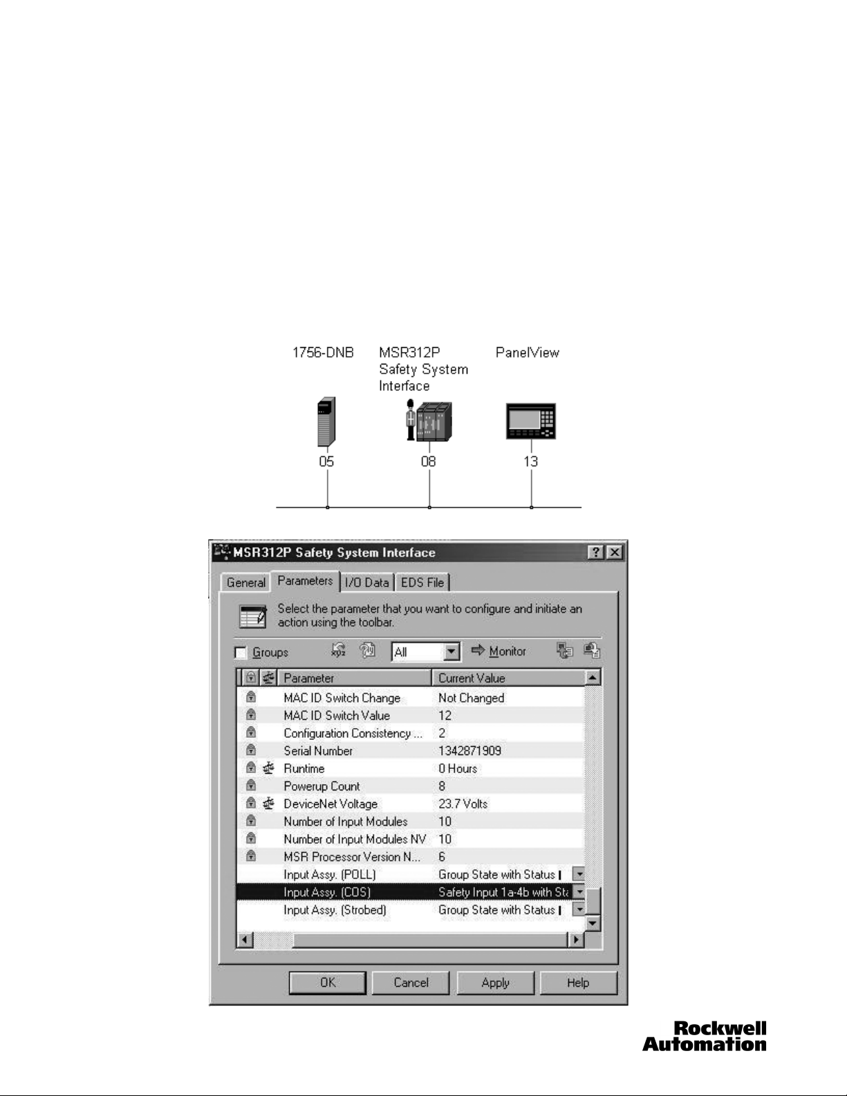
A simple system is setup to demonstrate messaging. The simple system consists of a 1756-DNB, the MSR312P, and a
PanelView 1000.
Example 1
Using Change Of State (COS) messaging, the Input Module Values 1…8, the Y34 Output and the System Status will be
displayed on the PanelView 1000. This information is located in Option 6 (165) of Parameter Input Assembly (COS).
Step 1. Select "165: 8 inputs and 1 output" (Safety Input 1a-4b with Status Y34 (2 bytes))
In the RSNetWorx Graph tab, double click on the MSR312P icon. Click on the Parameters tab, and scroll down to
Parameter 104. Click on the “Current Value” cell for Parameter Input Assembly (COS), and the drop down menu will
automatically appear. Select the desired option (in this case, 167). If you click on the “parameter help” icon, it will state the
number of input and output bytes required for each choice. This will be needed in the next step. Notice it states 2 bytes IN,
1 byte OUT. Click OK. This determines the data that will be sent to the 1756-DNB scanner via the COS connection.
18 MSR312-UM001B-EN-P
Page 19

Configurable Monitoring Safety Relay with DeviceNet™ Communications
Chapter 3: Quick Start Guide
Step 2. Add the MSR312P to the Scan List of DNB scanner.
Double-click the 1756-DNB icon. Click on the “Scanlist” tab. Highlight the MSR312P and click the right arrow in the middle of the
window to move the MSR312P to the Scanlist.
With the MSR312P still highlighted, click on the Edit I/O Parameters button.
MSR312-UM001B-EN-P 19
Page 20

Configurable Monitoring Safety Relay with DeviceNet™ Communications
Chapter 3: Quick Start Guide
Step 3. Set up I/O parameters for the MSR312P.
Verify the Strobed and Polled boxes are unchecked. Check the “Change of State/Cyclic” box. Set the Input Size to 2 and the
Output Size to 1. We knew the I/O sizes from the parameter help within the MSR312P Parameter (103, 104, 105). Select an
appropriate Heartbeat Rate. (Default is ok) Click OK.
20 MSR312-UM001B-EN-P
Page 21

Configurable Monitoring Safety Relay with DeviceNet™ Communications
Chapter 3: Quick Start Guide
Step 4. Configure the MSR312P Inputs.
Click on the “Input” Tab. The software automatically maps the Input data at the first available memory locations. Same as
selecting “Automap.” Let’s change the location of the data to start at word 10 instead of the default of word 0. Highlight the
MSR312P and click Advanced.
MSR312-UM001B-EN-P 21
Page 22

Configurable Monitoring Safety Relay with DeviceNet™ Communications
Chapter 3: Quick Start Guide
Step 5. Map the MSR312P Inputs.
In the “Map From:” box, set the Message value to COS. In the “Map To:” box, set the DWord value to 10. This value will be used
in the ladder logic program to place the values into the proper memory location.
If AutoMap was selected on the previous screen, then the user must adjust the ladder logic program to the appropriate memory
location.
Click “Apply Mapping” and then close the window.
22 MSR312-UM001B-EN-P
Page 23

Configurable Monitoring Safety Relay with DeviceNet™ Communications
Chapter 3: Quick Start Guide
Step 6. Configure the MSR312P Outputs.
Click on the “Output” Tab. The software automatically maps the Output data at the first available memory locations. Same as
selecting “Automap.” Let’s change the location of the data to start at word 10 instead of the default of word 0. Highlight the
MSR312P and click Advanced.
MSR312-UM001B-EN-P 23
Page 24

Configurable Monitoring Safety Relay with DeviceNet™ Communications
Chapter 3: Quick Start Guide
Step 7. Map the MSR312P Outputs
In the “Map From:” box, set the Message value to COS. In the “Map To:” box, set the DWord value to 10. This value will be used
in the ladder logic program to place the values into the proper memory location.
If AutoMap was selected on the previous screen, then the user must adjust the ladder logic program to the appropriate memory
location.
Click “Apply Mapping” and then close the window.
24 MSR312-UM001B-EN-P
Page 25

Configurable Monitoring Safety Relay with DeviceNet™ Communications
Chapter 3: Quick Start Guide
Step 8. Configure Auto Device Replacement (ADR).
To view/edit the auto device replacement parameters, click the ADR tab. Select the “Enable Auto-Address Recovery” box. Click
Load Device Config. Select “Configuration Recovery” and “Auto Address Recovery.”
ADR is helpful when a unit fails due to mechanical or internal damage and it needs to be replaced. Without any software tool,
the unit can be replaced with a brand new device and the 1756-DNB scanner will recognize the change and reprogram the node
address and configuration information of the new device to the same parameters as the original device.
Note: Be sure you have completely setup the MSR312P first and no additional changes to the unit will be required. When ADR
is enabled, the configuration information can not be saved into the device.
Note: If the MAC ID is set through the rotary switches, auto-address recovery will not be available for use. This option requires
the ability to reprogram the MAC ID, therefore, it must be software programmable.
For more information on scanner configuration, refer to the DeviceNet Scanner Configuration Manual (Publication 1756-6.5.15)
for the ControlLogix platform.
This completes the configuration needed to setup the MSR312P within the 1756-DNB scanner.
Note: If Parameter Input Assembly (COS), in this example had different I/O data (other than 167) the “Edit I/O Parameters”
settings would also be different. If a Polled I/O or Cyclic I/O was desired instead, using parameters Input Assembly Poll
or Strobe, the size of the data would not change but the scanner would need to be updated with “Polled” or “Cyclic”
instead of the “COS” used in this example.
Step 9. Configure the Panelview 1000 I/O data.
Repeat steps 2-7 for the Panelview 1000. Make sure the Panelview icon is selected within the 1756-DNB module then repeat
the same steps. In this example the panelview is configured with 20 words within the 1756-DNB scanner. The I/O data is located
from Dword 0 for both the input and output data. These are the default (Automap) locations.
MSR312-UM001B-EN-P 25
Page 26

Configurable Monitoring Safety Relay with DeviceNet™ Communications
Chapter 3: Quick Start Guide
Step 10. Set up the Ladder Logic Program.
A simple ladder logic program transfers the information back and forth between the MSR312P and the PanelView 1000.
The address of the Source and Destination must match the addresses set in the 1756-DNB input and output mapping in the
previous steps.
26 MSR312-UM001B-EN-P
Page 27

Configurable Monitoring Safety Relay with DeviceNet™ Communications
Chapter 3: Quick Start Guide
Example 2 — Explicit Messaging (UCMM)
This example requires a PanelView providing Explicit Messaging and MSR312P Series B. In this case, we are using a
PanelView 600 Touch. To configure communication and Indication Panel Builder 32 needs to be installed.
Please note that the PanelView must not have the same address like the MSR312P
Step 1. Setup PanelView - PC connection.
After the devices have been physically installed open RSLinx to setup connection to PanelView. Click the "Refresh" button to
update the node list.
MSR312-UM001B-EN-P 27
Page 28

Configurable Monitoring Safety Relay with DeviceNet™ Communications
Chapter 3: Quick Start Guide
Step 2. Create PanelView project.
Open Panel Builder to configure the PanelView 600 Touch (PV600) for DeviceNet. Click "New Project" and select "Creat a new
application" to open the configuration dialog box.
Name the project and choose the appropriate PanelView in the "Type" list. Highlight DeviceNet to enable the PV600 Touch for
DeviceNet communications and confirm your configuration by clicking "OK".
For more information on PanelView configuration, refer to the Panel ViewManual (Publication 6556-5.8).
The PanelView connections to other devices are created using addresses in the Tag Form dialog or Tag Editor.
For Read Tags: PanelView (client) initiates communications with Explicit "Get" message to obtain input data from the
MSR312P (Server). The MSR312P responds by sending data.
For Outputs: PanelView (Client) device sends data using Explicit "Set" Message to set output data. The MSR312P responds
that data has been received.
Note: Only Get_Attribute_Single and Set_Attribute_Single commands are supported. For PanelView objects with Explicit
Client addressing:
• Get_Attribute_Single: The PanelView sequentially scans values addressed to PanelView objects in the current screen (or
global objects) and reads data from the external server device.
• Set_Attribute_Single: The PanelView sends values to the external device when a change of state is detected on that
input.
28 MSR312-UM001B-EN-P
Page 29

Configurable Monitoring Safety Relay with DeviceNet™ Communications
Chapter 3: Quick Start Guide
Step 3. Using Read Tag to indicate Input1a state.
It is intended to display the Input 1 status of the First MSR320 Input module (Input 1a). For this a Multistate Indicator Object is
used as a Read Tag Select "Indicators" within the "Objects" menu and then "Multistate" to insert the indicator box into the Panel
View screen.
A double click on the Indicator box within the screen opens the dialog to configure the Tag.
Click "Edit Tag…" to configure the Read Tag and connection. Verify if the "Value" box is checked. The Read Tag "Data Format"
should be the same as Parameters data size configured in the "Tag Form" dialog.
The Tag must be configured according to its description within the EDS-File. To indicate "Input1a" Parameter 1 is used. (refer to
Parameter description).
MSR312-UM001B-EN-P 29
Page 30

Configurable Monitoring Safety Relay with DeviceNet™ Communications
Chapter 3: Quick Start Guide
The EDS-File defines Parameter 1 as follows:
Enter the "Tag Name", in this case "Input1a" and select "Unsigned Integer"(=1 byte) for the "Data Type" according to the
parameter size in byte mentioned in the EDS.
Check the "Explicit - Client" (Panel iew = Client) box and enter the MSR312P (server) node address.
The "Packet Bytes" are set to "2" per default for Read Tags. Enter the "class", "Instance" and "Attribute" value to address
"Parameter 1". The "Data Entry Limits" needs to match the appropriate Min, Max values of the EDS.
Confirm your configuration with "OK" and define the Indicator's message text in "States" register.
30 MSR312-UM001B-EN-P
Page 31

Configurable Monitoring Safety Relay with DeviceNet™ Communications
Chapter 3: Quick Start Guide
Step 4. Using Write Tag to set Semiconductor Output Y34.
The Y34 Parameters (Parameter 83…88) are partly configurable (refer to Parameter description). Its output state can be set by
using Parameter 83. Therefore a "Momentary" "Push Buttons" Object is added to the Project.
Open the Tag Form as described in Step 3. The PanelView 600 Touch provides the functionality to configure objects to simulate
a switching device by triggering the object on the screen. The selected Push Button is configured as follows:
Type: Momentary
Contacts: NO
Hold Time: 500ms (Default)
MSR312-UM001B-EN-P 31
Page 32

Configurable Monitoring Safety Relay with DeviceNet™ Communications
Chapter 3: Quick Start Guide
Verify if the "Single Bit" box is checked and click "Edit Tag…" to configure the communication in the Tag Form Dialog.
Select Messaging Type and node address as described in Step 3 and check the "Write Tag" box. Class, Instance and Attribute
are derived from the EDS file Parameter 83 description. Select "Bit" for "Data Type" and enter "1" for "Packet Bytes".
Click "OK" and set the Message Text in the "States" register.
The resulting PanelView screen looks as follows:
Finally download the application to the Panel View.
Step 5. Start Messaging.
Connect MSR312P and PanelView via DeviceNet and power the bus.
The state of Input 1 on the first MSR320 input module should now be displayed with the "State Input1a" Object on the
PanelView screen. Pushing the screen element configured to control Y34 should activate the semiconductor output (24V).
Note: For this to work correctly the output Y34 can not be owned by the PLC. So, the PLC can only use strobed. A conflict in
ownership of Y34 will cause an error on the PLC or PanelView depending on who acquired the connection first.
32 MSR312-UM001B-EN-P
Page 33

Configurable Monitoring Safety Relay with DeviceNet™ Communications
Chapter 4: Getting Online via RSNetWorx™ for DeviceNet™
Chapter 4: Getting Online via RSNetWorx™ for DeviceNet™
After connecting the MSR312P to the DeviceNet network, Open RSNetWorx for DeviceNet. Click “Network” then Select
“Online.”
Select the communication path.
Note: You must configure RSlinx first.
RSNetWorx requests you to synchronize your offline configuration with the online devices. Click OK.
MSR312-UM001B-EN-P 33
Page 34

Configurable Monitoring Safety Relay with DeviceNet™ Communications
Chapter 4: Getting Online via RSNetWorx™ for DeviceNet™
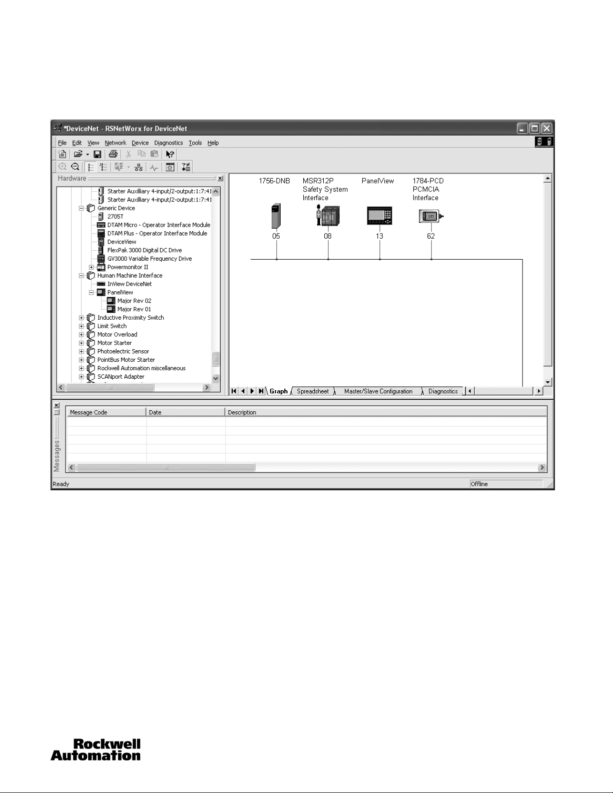
Upon successful completion, the devices on the network appear with their description and node address. The MSR312P, in this
case, has address 08.
Right click on the MSR312P, and select Properties.
The General properties of the MSR312P are shown. This window allows the viewing the individual parameters, the I/O data, and
the EDS file.
34 MSR312-UM001B-EN-P
Page 35

Configurable Monitoring Safety Relay with DeviceNet™ Communications
Chapter 4: Getting Online via RSNetWorx™ for DeviceNet™
Click on the parameter tab. The EDS Editor window appears. Click upload to read the current status of the MSR312P.
RSNetWorx reads in all the parameters, and then displays them. The window shows the first 14 parameters.
MSR312-UM001B-EN-P 35
Page 36

Configurable Monitoring Safety Relay with DeviceNet™ Communications
Chapter 4: Getting Online via RSNetWorx™ for DeviceNet™
Click on Monitor to continuously update the values of each parameter. When active, the Monitor field will be a white background
and an arrow will scroll down the left side.
Click on the I/O tab. The current message type is shown in bold. In this example, Strobed messaging is active.
36 MSR312-UM001B-EN-P
Page 37

Configurable Monitoring Safety Relay with DeviceNet™ Communications
Chapter 4: Getting Online via RSNetWorx™ for DeviceNet™
Click on the EDS tab. This tab provides the EDS file revision information. Use the View File button to view the contents of the
EDS file.
MSR312-UM001B-EN-P 37
Page 38

Configurable Monitoring Safety Relay with DeviceNet™ Communications
Chapter 4: Getting Online via RSNetWorx™ for DeviceNet™
38 MSR312-UM001B-EN-P
Page 39

Configurable Monitoring Safety Relay with DeviceNet™ Communications
Chapter 5: Unregister the EDS File
Chapter 5: Unregister the EDS File
Unregistering the EDS file is only required if the wrong file has been registered. This is not typically required. Close RSlinx if it is
already open.
Click on tools in RSNetWorx and select EDS Wizard.
Click “Next.”
MSR312-UM001B-EN-P 39
Page 40

Configurable Monitoring Safety Relay with DeviceNet™ Communications
Chapter 5: Unregister the EDS File
Check “Unregister a device” if replacing an older version of the EDS file. Click “Next.”
Click “Next.”
Click “Next” to unregister the device.
Click “Finish”.
40 MSR312-UM001B-EN-P
Page 41

Configurable Monitoring Safety Relay with DeviceNet™ Communications
Chapter 6: Register the MSR312P EDS Device
Open the EDS Wizard.
Chapter 6: Register the MSR312P EDS Device
Click “Next.”
MSR312-UM001B-EN-P 41
Page 42

Configurable Monitoring Safety Relay with DeviceNet™ Communications
Chapter 6: Register the MSR312P EDS Device
Click “Next.”
Click on the device showing in the Product Type window, then click Change icon. Scan through the ICON and select the
MSR312P standing next to the safety relay.
42 MSR312-UM001B-EN-P
Page 43

Configurable Monitoring Safety Relay with DeviceNet™ Communications
Chapter 6: Register the MSR312P EDS Device
Click “Next.”
Click “Next” to register the device.
Click “Finish.”
MSR312-UM001B-EN-P 43
Page 44
Configurable Monitoring Safety Relay with DeviceNet™ Communications
Chapter 7: Off-Line Node Recovery
Chapter 7: Off-Line Node Recovery
Overview
The MSR312P base module is equipped with a function known as Off-Line Node Recovery. Off-Line Node Recovery is used
mainly to commission a device on a network. When a new product is put on the network, it is at a default address of Node 63. If
multiple units are placed on a network without first using node commissioning to change the node address a duplicate MAC ID
error occurs. This means that more than one device is located at the same node address and only one of them is allowed online.
Off-Line Node Recovery now allows you to recover the faulted devices and change the node address. This is a powerful tool
because multiple nodes can be put on the network on installation and recovered one at a time without having to continually reset
the network. The following section will walk through a sample recovery.
Note: If the MAC ID is set through the rotary switches, Off-Line Node Recovery will not be able to recover the faulted device
because it cannot change the node address.
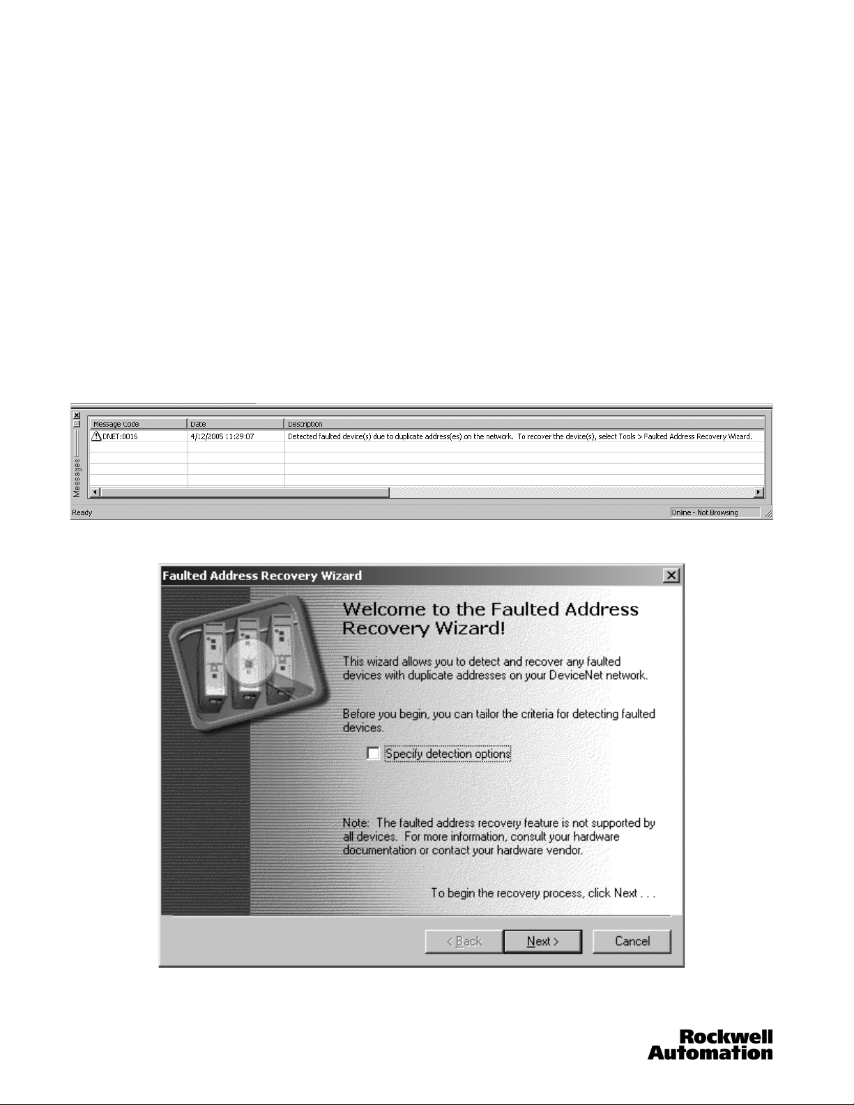
Sample Recovery
This example has placed two MSR312P base modules on a network at the same node address 63.
From RSNetWorx, click the Single Pass Browse button. The following message will appear in the message box at the bottom of
the screen.
Select Faulted Address Recovery Wizard from the Too ls menu.
Click the “Next” button.
44 MSR312-UM001B-EN-P
Page 45

Configurable Monitoring Safety Relay with DeviceNet™ Communications
Chapter 7: Off-Line Node Recovery
If there are multiple faulted devices, they will show up in the list. Devices are identified by the DeviceNet serial number that is
unique to every product. The serial number for the MSR312P base module can be located on the name plate or inside the
product. Click the “Next” button.
If there are multiple faulted units, you can verify which unit you are recovering by flashing the Mod/Net Status LED. To do this
click “Flash LED.” The LED will flash between red and green. Click “00” under New Address to change the new address.
MSR312-UM001B-EN-P 45
Page 46

Configurable Monitoring Safety Relay with DeviceNet™ Communications
Chapter 7: Off-Line Node Recovery
Change the address to the new address (for example, 22) and click “Recover.” Recovery is now complete.
For more information on Off-Line Node Recovery refer to the RSNetWorx for DeviceNet User Manual (Publication 1787-6.5.3).
46 MSR312-UM001B-EN-P
Page 47

Configurable Monitoring Safety Relay with DeviceNet™ Communications
Chapter 7: Off-Line Node Recovery
MSR312-UM001B-EN-P 47
Page 48

Configurable Monitoring Safety Relay with DeviceNet™ Communications
Chapter 8: DeviceNet Classes and Objects
Chapter 8: DeviceNet Classes and Objects
Objects with common attributes are members of the same “Class.” A particular occurrence of an object is called an instance of
that class. The class and instance identifier within a DeviceNet connection message will identify exactly what object is being
referenced. In an effort to remain compatible with other DeviceNet devices, the DeviceNet implementation follows standard
definitions of objects.
Common Services
All Objects support the following services.
Service Code Service Name Description of Service
0x0E Get_Attribute_Single Returns the contents of the specified attribute
0x10 Set_Attribute_Single Configures an attribute
Identity Object
Class Code: 01
This object is used to provide identification and general information about the module.
Class Services
As a group 2 slave device, the MSR312P base module supports the following class services and instance services.
Service Code Service Name Service Code Service Name
0x0E Get_Attribute_Single 75 (0x4B) Allocate Group 2 Identifier Set
0x10 Set_Attribute_Single 76 (0x4C) Release Group 2 Identifier Set
hex
Object Classes
Objects with common attributes are members of the same class. A particular occurrence of an object is called an instance of
that class. The class and instance identifier within a DeviceNet connection message will identify exactly what object is being
referenced. In an effort to remain compatible with other DeviceNet devices, the DeviceNet implementation for the MSR312P
base module follows standard definitions of objects. The classes listed below will be supported by the MSR312P base module.
This object is used to provide identification and general information about the module. This object must be supported per the
DeviceNet specification. There will only be one instance of this object. Attributes such as the vendor id, serial number, or
product revision will be maintained by this object.
The following object classes will be supported.
Class Object Class Object
0x0001 Identity 0x0008 Discrete Input Point
0x0002 Message Router 0x0009 Discrete Output Point
0x0003 DeviceNet 0x001D Discrete Input Group
0x0004 Assembly 0x002B Acknowledge Handler
0x0005 Connection
48 MSR312-UM001B-EN-P
Page 49

Configurable Monitoring Safety Relay with DeviceNet™ Communications
Chapter 8: DeviceNet Classes and Objects
Class Code 0x0001: Identity Object
None of the optional class attributes of the Identity Object will be supported.
A single instance (instance 1) of the Identity Object will be supported. The following instance attributes will be
supported.
Attribute ID Access Rule Name Data Type Value
1 Get Vendor UINT 1
2 Get Device Type UINT 12
3 Get Product Code UINT 172 (0xAC)
4 Get Revision Major Revision Minor
Revision
5 Get Status WORD 0 = not owned 1 = owned by master
6 Get Serial Number UDINT unique number for each device
7 Get Product Name String Length ASCII
String
9 Get Configuration Consistency Value UINT Unique value depending on output
10 Set Heartbeat Time USINT Time in seconds to produce
73 Get Power Up Count UINT Increments by one at each power up
74 Get Runtime UNIT Running total, units = 2 hours, NV
176 Get DeviceNet Voltage USINT DeviceNet voltage at connector
177 Get MSR Processor Version UNIT Revision of the MSR processor
Structure of: USINT 1 1
Structure of: USINT STRING
of the parameter checksum
algorithm.
heartbeat message
value updated every 2 hours.
firmware
The following common services will be implemented for the Identity Object.
Implemented for:
Service Code
0x0E No Yes Get_Attribute_Single
0x05 Yes Yes Reset
0x10 Yes Yes Set Single
Service NameClass Instance
Class Code 0x0002: Message Router Object
No class or instance attributes will be supported. The message router object exists only to rout explicit messages to other
objects.
Class Code 0x0003: DeviceNet Object
The following class attributes will be supported for the DeviceNet Object:
Attribute ID Access Rule Name Data Type Value
1 Get Revision UINT 1
MSR312-UM001B-EN-P 49
Page 50

Configurable Monitoring Safety Relay with DeviceNet™ Communications
Chapter 8: DeviceNet Classes and Objects
A single instance (instance 1) of the DeviceNet Object will be supported. The following instance attributes will be
supported.
Attribute ID Access Rule Name Data Type Value
1 Get/Set Node Address USINT 0…63
2 Get/Set Baud Rate USINT 0 = 125 K 1 = 250 K 2 = 500 K
6 Get MAC ID Switch Changed BOOL 0 = No Change 1 = Change since
last Reset or Power-Up
7 Get Baud Rate Switch Changed BOOL 0 = No Change 1 = Change since
8 Get MAC ID Switch Value USINT 0…99 0…63 Hardware Set 64…99
9 Get Baud Rate Switch Value USINT 0…9 0…2 Hardware Set 3…9
10 Set Quick Connect BOOL 0 = Disable; 1 = Enable
100 (64hex)
Get/Set Autobaud Enable BOOL 0 = Enabled 1 = Disabled
The following services will be implemented for the DeviceNet Object.
Implemented for:
Service Code
0x0E Yes Yes Get_Attribute_Single
0x10 No Yes Set_Attribute_Single
0x4B No Yes Allocate_Master/Slave _Connection_Set
0x4C No Yes Release_Master/Slave _Connection_Set
Service NameClass Instance
last Reset or Power-Up
Software Configurable
Software Configurable
Class Code 0x0004: Assembly Object
The following class attributes will be supported for the Assembly Object:
Attribute ID Access Rule Name Data Type Value
2 Get Max Instance UINT 171
Assemblies
The following Assembly Instances will be implemented.
Instances supported:
Instance Input Bytes Output Bytes IO format
160 1 0 Group State with Status Bit
161 2 0 Diagnostics
162 1 0 2 Point Input with no Status Bit
163 1 0 8 Point Input with no Status Bit
164 1 0 2 Point Input with Single Status Bit
165 2 0 8 Point Input with Single Status Bit
166 0 1 1 Point Output
167 3 1 20 Point Input and 1 Point Output with Single Status Bit
168 1 1 2 Point Input and 1 Point Output with Single Status Bit
169 1 0 Group State with no Status Bit
170 3 0 20 Point Input with no Status Bit
171 3 0 20 Point Input with Single Status Bit
Instance 160 (Group State w/Status Bit)
Byte Bit 7 Bit 6 Bit 5 Bit 4 Bit 3 Bit 2 Bit 1 Bit 0
0 Reserved Reserved
1 Reserved Reserved Reserved
Group 3
Active
Group 3
Ready
Group 3
Interrupted
Group 2
Active
Reserved
Group 2
Ready
Group 2
Interrupted
Group 1
Active
Reserved
50 MSR312-UM001B-EN-P
Group 1
Ready
Group 1
Interrupted
Page 51

Configurable Monitoring Safety Relay with DeviceNet™ Communications
Chapter 8: DeviceNet Classes and Objects
Instance 161 (Diagnostics)
Byte Bit 7 Bit 6 Bit 5 Bit 4 Bit 3 Bit 2 Bit 1 Bit 0
Current config
0
1 Reserved Reserved Reserved Reserved
unlike stored
config
Any hardware
failure
Config
changed
during
operation
Terminal
connector is
missing
Instance 162 (2 Point Input w/no Status Bit)
Byte Bit 7 Bit 6 Bit 5 Bit 4 Bit 3 Bit 2 Bit 1 Bit 0
0 Reserved Reserved Reserved Reserved Reserved Reserved Input 1b State Input 1a State
Instance 163 (8 Point Input w/no Status Bit)
Byte Bit 7 Bit 6 Bit 5 Bit 4 Bit 3 Bit 2 Bit 1 Bit 0
0 Input 4b State Input 4a State Input 3b State Input 3a State Input 2b State Input 2a State Input 1b State Input 1a State
Instance 164 (2 Point Input w/Single Status Bit)
Byte Bit 7 Bit 6 Bit 5 Bit 4 Bit 3 Bit 2 Bit 1 Bit 0
0 Device Fault Reserved Reserved Reserved Reserved Reserved Input 1abState Input 1a State
Internal Fault
(cpFaults1 <> 0)Cross Loop
Reserve Lamp
2 Faulty
Muting Lamp
2 Faulty
Actual #
Modules not
equal to NV
Reserve Lamp
1 Faulty
Invalid code
switch setting
Muting Lamp
1 Faulty
Instance 165 (8 Point Input w/Single Status Bit)
Byte Bit 7 Bit 6 Bit 5 Bit 4 Bit 3 Bit 2 Bit 1 Bit 0
0 Input 4b State Input 4a State Input 3b State Input 3a State Input 2b State Input 2a State Input 1b State Input 1a State
1 Device Fault Reserved Reserved Reserved Reserved Reserved Reserved Reserved
Instance 166 (1 Point Output)
Byte Bit 7 Bit 6 Bit 5 Bit 4 Bit 3 Bit 2 Bit 1 Bit 0
0 Reserved Reserved Reserved Reserved Reserved Reserved Reserved
Instance 167 (20 Point Input and 1 Point Output w/Single Status Bit)
Byte Bit 7 Bit 6 Bit 5 Bit 4 Bit 3 Bit 2 Bit 1 Bit 0
0 Input 4b State Input 4a State Input 3b State Input 3a State Input 2b State Input 2a State Input 1b State Input 1a State
1 Input 8b State Input 8a State Input 7b State Input 7a State Input 6b State Input 6a State Input 5b State Input 5a State
2 Device Fault Output 1 State Reserved Reserved
Input 10b
State
Input 10a
State
Input 9b State Input 9a State
Instance 168 (2 Point Input and 1 Point Output w/Single Status Bit)
Byte Bit 7 Bit 6 Bit 5 Bit 4 Bit 3 Bit 2 Bit 1 Bit 0
0 Device Fault Output 1 State Reserved Reserved Reserved Reserved Input 1b State Input 1a State
Instance 169 (Group State w/no Status Bit)
Byte Bit 7 Bit 6 Bit 5 Bit 4 Bit 3 Bit 2 Bit 1 Bit 0
0 Reserved Reserved
Group 3
Active
Group 3
Ready
Group 2
Active
Group 2
Ready
Group 1
Active
Output 1 State
(Y34)
Group 1
Ready
Instance 170 (20 Point Input w/no Status Bit)
Byte Bit 7 Bit 6 Bit 5 Bit 4 Bit 3 Bit 2 Bit 1 Bit 0
0 Input 4b State Input 4a State Input 3b State Input 3a State Input 2b State Input 2a State Input 1b State Input 1a State
1 Input 8b State Input 8a State Input 7b State Input 7a State Input 6b State Input 6a State Input 5b State Input 5a State
2 Reserved Reserved Reserved Reserved
Input 10b
State
Input 10a
State
Input 9b State Input 9a State
MSR312-UM001B-EN-P 51
Page 52

Configurable Monitoring Safety Relay with DeviceNet™ Communications
Chapter 8: DeviceNet Classes and Objects
Instance 171 (20 Point Input w/Single Status Bit)
Byte Bit 7 Bit 6 Bit 5 Bit 4 Bit 3 Bit 2 Bit 1 Bit 0
0 Input 4b State Input 4a State Input 3b State Input 3a State Input 2b State Input 2a State Input 1b State Input 1a State
1 Input 8b State Input 8a State Input 7b State Input 7a State Input 6b State Input 6a State Input 5b State Input 5a State
2 Device Fault Reserved Reserved Reserved
Input 10b
State
Input 10a
State
Input 9b State Input 9a State
Note: Response time is assembly dependant, and will vary depending upon the number of input modules attached to the
system. The response time will be longest with ten input modules attached.
Input Modules Response time
One 16.2mS
Ten 56.4mS
Class Code 0x0005: Connection Object
No class attributes will be supported for the Connection Object. Five instances of the Connection Object will be supported.
Instance 1 will be the explicit message connection, instance 2 will be the polled IO connection, and instance 4 will be the COS/
Cyclic IO connection. Instance 1 is the Predefined Group 2 Connection Set Explicit Message Connection. The following
instance 1 attributes will be supported:
Attribute ID Access Rule Name Data Type Value
1 Get State USINT 0 = non-existent 1 = configuring 3 =
established 4 = timed out
2 Get Instance Type USINT 0 = Explicit Message
3 Get Transport Class Trigger BYTE 0x83 — Server, Transport Class 3
4 Get Produced Connection ID UINT 10xxxxxx011 xxxxxx = node
address
5 Get Consumed Connection ID UINT 10xxxxxx100 xxxxxx = node
6 Get Initial Comm Characteristics BYTE 0x22
7 Get Produced Connection Size UINT 0x61
8 Get Consumed Connection Size UINT 0x61
9 Get/Set Expected Packet Rate UINT In milliseconds
12 (OChex)
13 (ODhex)
14 (OEhex)
15 (OFhex)
16 (10hex)
Get Watchdog Action USINT 01 = auto delete 03 = deferred
Get Produced Connection Path Length UINT 0
Get Produced Connection Path EPATH Empty
Get Consumed Connection Path Length UINT 0
Get Consumed Connection Path EPATH Empty
address
delete
52 MSR312-UM001B-EN-P
Page 53

Configurable Monitoring Safety Relay with DeviceNet™ Communications
Chapter 8: DeviceNet Classes and Objects
Instance 2 is the Predefined Group 2 Connection Set Polled I/O Message Connection. The following instance 2
attributes will be supported:
Attribute ID Access Rule Name Data Type Value
1 Get State USINT 0 = non-existent 1 = configuring 3 =
established 4 = timed out
2 Get Instance Type USINT 1 = I/O Connection
3 Get Transport Class Trigger USINT 0x82 — Server, Transport Class 2 (If
4 Get Produced Connection ID UINT 01111xxxxxx xxxxxx = node
5 Get Consumed Connection ID UINT 10xxxxxx101 xxxxxx = node
6 Get Initial Comm Characteristics USINT 0x21
7 Get Produced Connection Size UINT 0…8
8 Get Consumed Connection Size UINT 0…8
9 Get/Set Expected Packet Rate UINT In milliseconds
12 (OChex)
13 (ODhex)
14 (OEhex)
15 (OFhex)
16 (10hex)
Get/Set Watchdog Action USINT 0 = transition to timed out 1 = auto
Get Produced Connection Path Length UINT 6
Get/Set Produced Connection Path —
Get Consumed Connection Path Length UINT 6
Get/Set Consumed Connection Path —
alloc_choice ! = polled and ack
suppression is enabled then value =
0x80)
address
address
delete 2 = auto reset
Instance 4 is the Predefined Group 2 Connection Set Change of State/Cyclic I/O Message Connection. The following
instance 4 attributes will be supported:
Attribute ID Access Rule Name Data Type Value
1 Get State USINT 0 = non-existent 1 = configuring 3 =
established 4 = timed out
2 Get Instance Type USINT 1 = I/O Connection
3 Get Transport Class Trigger USINT 0x00 (Cyclic, unacknowledged)
4 Get Produced Connection ID UINT 01101xxxxxx xxxxxx = node
5 Get Consumed Connection ID UINT 10xxxxxx101 xxxxxx = node
6 Get Initial Comm Characteristics USINT 0x01 (acknowledged) 0x0F
7 Get Produced Connection Size UINT 0…8
8 Get Consumed Connection Size UINT 0…8
9 Get/Set Expected Packet Rate UINT In milliseconds
12 (OChex)
13 (ODhex)
14 (OEhex)
15 (OFhex)
16 (10hex)
17 (11hex)
Get Watchdog Action USINT 0 = transition to timed out 1 = auto
Get Produced Connection Path Length UINT 6
Get Produced Connection Path —
Get Consumed Connection Path Length UINT 4 (acknowledged) 0
Get/Set Consumed Connection Path —
Get/Set Production Inhibit Time UINT In milliseconds
0x03 (Cyclic, acknowledged) 0x10
(COS, unacknowledged) 0x13
(COS, acknowledged)
address
address
(unacknowledged)
delete 2 = auto reset
(unacknowledged)
MSR312-UM001B-EN-P 53
Page 54

Configurable Monitoring Safety Relay with DeviceNet™ Communications
Chapter 8: DeviceNet Classes and Objects
The following common services will be implemented for the Connection Object.
Implemented for:
Service Code
0x0E No Yes Get_Attribute_Single
0x10 No Yes Set_Attribute_Single
Service NameClass Instance
Class Code 0x0008: Discrete Input Point Object
The following class attributes will be supported for the Discrete Input Point Object.
Attribute ID Access Rule Name Data Type Value
1 Get Revision UINT 2
Multiple instances of the Discrete Input Point Object will be supported. All instances will contain the following
attributes.
Attribute ID Access Rule Name Data Type Value
3 Get Value BOOL 0 = OFF, 1 = ON
118 Get Function Switch USINT 0-9
119 Get Function Switch NV USINT 0-9
120 Get Group Switch USINT 0-9
121 Get Group Switch NV USINT 0-9
122 Get Count of Extension Modules USINT 0-10
123 Get Count of Extension Modules NV USINT 0-10
124 Get Simultaneity Enabled USINT 0-7
125 Get Simultaneity Errors USINT 0-7
126 Get Muting Lamp Faults USINT 0-7
127 Get Input Mod Faults USINT 0-3
129 Get Input Modules State USINT 0-7
131 Get Any system fault BOOL 0 = No Faults, 1 = Fault(s) Present
The following common services will be implemented for the Discrete Input Point Object.
Implemented for:
Service Code
0x0E Yes Yes Get_Attribute_Single
0x10 No Yes Set_Attribute_Single
Service NameClass Instance
Class Code 0x0009: Discrete Output Point Object
No class attributes will be supported for the Discrete Input Object:
Multiple instances of the Discrete Output Point Object will be supported. All instances will contain the following
attributes.
Attribute ID Access Rule Name Data Type Value
3 Get/Set Value BOOL 0 = OFF, 1 = ON
4 Get Status BOOL 0 = OK, 1 = Faulted
5 Get/Set Fault Action BOOL 0 = Fault Value attribute, 1 = Hold
Last State
6 Get/Set Fault Value BOOL 0 = OFF, 1 = ON
7 Get/Set Idle Action BOOL 0 = Fault Value attribute, 1 = Hold
8 Get/Set Idle Value BOOL 0 = OFF, 1 = ON
The following common services will be implemented for the Discrete Output Point Object.
Implemented for:
Service Code
0x0E Yes Yes Get_Attribute_Single
0x10 No Yes Set_Attribute_Single
Service NameClass Instance
Last State
54 MSR312-UM001B-EN-P
Page 55

Configurable Monitoring Safety Relay with DeviceNet™ Communications
Chapter 8: DeviceNet Classes and Objects
Class Code 0x001D: Discrete Input Group Object
This object maintains any attributes that apply to all instances of Discrete Input Points so they can be addressed as a
group.
Attribute ID Access Rule Name Data Type Value
5 Get Status BOOL 0 = OK, 1 = Interrupted
103 Get Group State BOOL 0 = Ready, 1 = Active
104 Get Group Reset State USINT 0, “Groups 1, 2 and 3: Auto,”
1, “Group 3: Auto, Groups 1 and 2: Manual,”
2, “Groups 1 and 2: Auto, Group 3: Manual,”
3. “Groups 1, 2 and 3: Manual.”
105 Get Group EDM Status BOOL 0 = Open, 1 = Closed
The following common services will be implemented for the Parameters Object.
Implemented for:
Service Code
0x0E Yes Yes Get_Attribute_Single
0x10 No Yes Set_Attribute_Single
Service NameClass Instance
Class Code 0x002B: Acknowledge Handler Object
No class attributes will be supported for the Acknowledge Handler Object.
A single instance (instance 1) of the Acknowledge Handler Object will be supported. The following instance attributes
will be supported.
Attribute ID Access Rule Name Data Type Value
1 Get/Set Acknowledge Timer UINT ms
2 Get Retry Limit USINT 1
3 Get COS Producing Connection
Instance
UINT 4
The following common services will be implemented for the Acknowledge Handler Object.
Implemented for:
Service Code
0x0E No Yes Get_Attribute_Single
0x10 No Yes Set_Attribute_Single
Service NameClass Instance
MSR312-UM001B-EN-P 55
Page 56

Supersedes Publication MSR312-UM001A-EN-P — February 2007
Publication MSR312-UM001B-EN-P — October 2008
 Loading...