

Page 1
Deutsch /
Français
(b) Description
The CU3 has been designed to detect motion of single phase or three phase
motors, by measuring the back electro magnetic field (e.m.f) of the motor
on two terminals of one stator winding. When the supply is turned down to
zero or disconnected and the back e.m.f. is less than 0.5 volts AC (motor
stops), the safety outputs 13-14 & 23-24 close. This enables the output
devices (e.g. solenoid locking / unlocking switch) to be activated.
NOTE 1: This unit may not be suitable for some variable speed and
frequency inverter drives because there may be a residual voltage of more
than 0.5 volts AC with the motor stopped.
NOTE 2: This unit senses motor movement. For applications where slipping
or disconnection can occur between the motor and the dangerous moving
parts, the Guardmaster CU2 Stop Motion Detector may be more
appropriate.
(a) Description
Le CU3 a été conçu pour détecter le mouvement d’un moteur monophasé
ou triphasé, en mesurant la force contre électro-motrice (f.e.m) du moteur
sur 2 bornes d’un bobinage stator. Quand l’alimentation s’inverse au point
zéro ou se coupe et que la force contre électro-motrice passe en dessous
de 0.5 volts AC (moteur arrêté), les sorties de sécurité 13-14 & 23-24 se
ferment. Elles permettent d’enclencher des appareils (gâches
électromagnétiques ou interverrouillages par exemple).
NOTE1 : Ce relais de sécurité ne peut pas être utilisé avec certains
variateurs de vitesse à fréquences variables car ils peuvent délivrer une
tension résiduelle supérieure à 0.5 volts AC alors que le moteur est arrêté.
NOTE2 : Ce relais de sécurité détecte le mouvement du moteur. Pour les
applications où une rupture de liaison mécanique pourrait se produire
entre le moteur et les éléments dangereux en mouvement, le détecteur
d’arrêt de mouvement CU2 de Guardmaster sera plus adapté.
Beschreibung
Der CU3 wurde entwickelt um die Bewegung von 1-phasigen oder 3phasigen Motoren zu überwachung, indem das elektromagnetische Feld
(EMK) des Motors an zwei Anschlüssen einer Stator-Windung gemessen
wird. Wenn die Spannung abgeschaltet oder unterbrochen wird und die
EMK ist kleiner als 0,5 Volt AC(Motor Stop), schließen die Sicherheits
Ausgänge 13-14 & 23-24. Dies aktiviert die Ausgangsgeräte
Sicherheitszuhaltung / Sicherheitsschalter).
Bemerkung 1: Dieses Gerät ist nicht nutzbar für manche WechselrichterAntriebe da hier eine größere Restspannung als 0,5 Volt AC bei
gestopptem Motor gemessen werden kann.
Bemerkung 2: Dieses Gerät detektiert eine Motor Bewegung. Bei
Anwendungen bei denen ein Rutschen oder eine Trennung zwischen Motor
und gefährlichen Bewegungen entstehen kann sollte der Guardmaster
CU2 Stillstandswächter eingesetzt werden.
(c) Mount in enclosure to a min
of IP 54.
(b) Mount on 35mm DIN rail.
(a) Back View
MOTOR STOPPED MOTION / SLOW SPEED DETECTOR
MEßWERTGEBER FÜR MOTOR-STILLSTAND / LANGSAMLAUF
DÉTECTEUR D'ARRÊT MOTEUR/DÉTECTEUR DE VITESSE LENTE
Einbauanleitung
(c) Installation Instructions
Notice d'installation
RETAIN THESE INSTRUCTIONS
Installation must be in accordance with the following steps and must be carried out
by suitably competent personnel.
This device is intended to be part of the safety related control system of a
machine. Before installation, a risk assessment should be performed to determine
whether the specifications of this device are suitable for all foreseeable
operational and environmental characteristics of the machine to which it is to be
fitted.
At regular intervals during the life of the machine check whether the
characteristics foreseen remain valid.
Guardmaster cannot accept responsibility for a failure of this device if the
procedures given in this sheet are not implemented or if it is used outside the
recommended specifications in this sheet.
Exposure to shock and/or vibration in excess of those stated in
IEC 68 part: 2-6/7 should be prevented.
Adherence to the recommended inspection and maintenance instructions forms
part of the warranty.
DIESE ANLEITUNG AUFBEWAHREN
Die Montage ist entsprechend den folgenden Schritten durch geeignet
qualifiziertes Fachpersonal durchzuführen.
Die Vorrichtung ist als Teil eines sicherheitsrelevanten Kontrollsystems einer
Maschine beabsichtigt. Vor der Installation sollte eine Risikobewertung zur
Festlegung dessen erfolgen, ob die Spezifikationen dieser Vorrichtung für alle
vorhersehbaren betrieblichen und umweltbezogenen Eigenschaften der
jeweiligen Maschine geeignet sind, an der sie installiert werden soll.
Zu regelmäßigen Abständen während der Lebensdauer der Maschine
überprüfen, ob die vorgesehenen Eigenschaften weiterhin zutreffen.
Guardmaster kann keinerlei Verantwortung für ein Versagen dieser
Vorrichtung übernehmen, wenn die in diesem Datenblatt gegebenen
Verfahrensweisen nicht implementiertt werden, oder wenn sie außerhalb der
auf diesem Blatt empfohlenen Spezifikationen verwendet wird.
Eine Aussetzung an Stoßbelastungen und/oder Vibrationen, die überhalb den
in IEC 68, Teil 2-6/7 angegebenen Werten liegen, sollte verhindert werden.
Die Einhaltung der empfohlenen Inspektions- und Wartungsvorschriften formt
Teil der Garantie.
GARDEZ EN MÉMOIRE CES INSTRUCTIONS :
L’installation devra suivre les étapes suivantes et sera effectuée par du
personnel compétent et qualifié.
Ce système est conçu pour être implanté dans la partie sécurité du système de
commande d’une machine. Avant l’installation, il faut effectuer une
appréciation des risques pour vérifier que les caractéristiques de cet appareil
sont appropriées aux critères d’utilisation et d’environnement de la machine.
Pendant toute la vie de la machine, en respectant des périodes de vérifications
régulières, Assurez-vous que l’appareil conserve ses performances. Si
nécessaire, remplacez l’appareil. Guardmaster n’accepte pas la responsabilité
d’une panne de cet appareil si les procédures décrites dans la présente notice
n’ont pas été respectées ou si l’appareil est utilisé en dehors des
recommandations décrites.
Evitez d’exposer l’appareil à des chocs et/ou des vibrations supérieurs à ceux
définis dans la norme CEI 68 part. 1-6/7.
Le respect des périodes de vérifications régulières, des instructions relatives au
contrôle et à l’entretien font parties intégrantes de la garantie.
21
(a) Connections
A1 Z1
23 3113X1
(b) LED Indication
POWER (RED) - Illuminated when
there is power to the unit.
STOP (GREEN) - Illuminated when
motor is stopped or at pre-set slow speed.
FAULT (YELLOW) - Illuminated when
a fault is detected.
RUN (RED) - Illuminated when
motor is running or exceeding the
pre-set slow speed.
A2 Z2
24 3214X2
A1 & A2 = Supply 230V AC or 110V AC or 24V AC/DC. (see side for details)
Z1 & Z2 = Input from motor supply.
X1 & X2 = Outputs (contactor) monitoring
13 & 14 = Safety output 1 (N/O).
23 & 24 = Safety output 2 (N/O).
31 x 32 = Auxiliary output (N/C).
1
(a) Rückansicht /
Vue de l’arrière.
(b) Auf 35 mm DIN-Schiene montieren /
Monter sur rail DIN de 35 mm.
(c) In Gehäuse nach mindestens IP 54 einbauen
1c A installer dans coffret IP54 minimum.
2
(a) Anschlüsse
A1 und A2 = Versorgungsspannung 230 V AC, 110 V AC
oder 24 V AC/DC (siehe Angaben an der Seite)
Z1 und Z2 = Eingang von Motoreinspeisung
X1 und X2 = Ausgänge (Schützüberwachung)
13 und 14 = Schutzausgang 1(Arbeitskontakt)
23 und 24 = Schutzausgang 2 (Arbeitskontakt)
31 und 32 = Hilfsausgang (Ruhekontakt)
Connexions
A1 et A2 = Alimentation 230V o 110V c.a. ou 24V AC/DC (voir les
informations détaillées sur le côté)
Z1 et Z2 = entrée provenant de l’alimentation du moteur
X1 et X2 = Boucle de retour (contacteurs)
13 et 14 = Sortie de sécurité 1 (N/O)
23 et 24 = Sortie de sécurité 2 (N/O)
31 et 32 = Sortie auxiliaire (N/F)
(b) ILED-Anzeigen
STROM EIN (ROT) - leuchtet bei Spannungsversorgung zum Gerät auf.
STOP (GRÜN) - leuchtet bei Motorstillstand oder bei voreingestellter
Langsamdrehzah auf.
FEHLER (GELB) - leuchtet bei Erfassung eines Fehlers auf.
MOTOR DREHT (ROT) - leuchtet bei l aufendem Motor, oder bei
Überschreitung der voreingestellten Langsamdrehzahl auf.
Voyants
POWER (rouge) - Allumé lorsque l’appareil est sous tension
STOP (vert) - Allumé lorsque le moteur est arrêté ou fonctionne à un
ralenti préréglé
FAULT (jaune) = Allumé lors de la détection d’un défaut
RUN (rouge) = Allumé lorsque le moteur est en marche ou fonctionne à
une vitesse supérieure au ralenti préréglé.
(a)
(b) Auswechselbare Sicherung 500 mAT /
Fusible remplaçable.
(c) Auf Abfahrverhalten der Maschine und Motorempfindlichkeit justieren.
Vor erneutem Normalbetrieb der Maschine darauf achten, daß die
Justierungen zum Stillstand oder der erforderlichen Langsamdrehzahl
des Motors führen, bevor die Ausgänge 13 und 14 sowie 23 - 24
geschlossen werden.
Ajuster en fonction de la rotation par inertie de la machine et de la
sensibilité du moteur. Avant de remettre la machine en marche normale,
vérifier que le réglage détermine l’arrêt du moteur ou le ralentissement
désiré avant de fermer les sorties à 13-14 et 23-24.
(d) 35001 Verbindung für 24V ac speisung abnehmen /
35001
Supprimer la liaison pour un fonctionnement en 24V c.a.
(e) Das 440R-S35001 benotigt bei 24-V-DC-Betrieb eine
potentialgetrennte Versorgung /
Le 440R-S35001 necessite une
alimentation isolee quand il foncionne en 24V c.c.
3
(a) Isolate power before removing cover
(b) Replacable fuse.
500 mAT
3
(c) Adjust to suit machine run down and motor
sensitivity.
Before allowing normal machine operation check
that the setting results in motor stopped or
required slow speed before the outputs at 13-14
& 23-24 are closed.
Vor Entfernung der Abdeckung, die Einspeisung trennen
Couper l’alimentation avant d’enlever le couvercle
(d) 35001
Remove link for 24V ac
operation
(e) The 440R-S35001
requires an
isolated supply
when operating
on 24V DC
R
CU3
Page 2
A1 Z1 X1 13 23 31
A2 Z2 X2 14 24 32
A2 Z2 X2 14 24 32
A1 Z1 X1 13 23 31
L
N
FUSE 500mA
FUSE 500mA
CU3
Control Unit
M
L
L1
L2
L3
CU3
Control Unit
M
N
K1(AUX)
START
MOMENTARY
PUSH
BUTTON
STOP
LATCHING
PUSH
BUTTON
K1 K2
AUXILIARY CIRCUIT
(CONTACT STATUS INDICATION)
12
22
34
11
21
33
GUARDMASTER
TLS-GD2: TLS1
solenoid
locking switch.
FUSES
41
42
53
54
A1
A2
AUXILIARY CIRCUIT
(LOCK STATUS INDICATION)
K2(AUX)
K1
(AUX)
K2
(AUX)
M
K1
K2
L1
500mA
500mA
L2
L3
GUARD
CLOSED
24VAC/DC, 110VAC, 230VAC
SOLENOID
A1 Z1 X1 13 23 31
A2 Z2 X2 14 24 32
CU3
Control Unit
4
5 6 WARNING
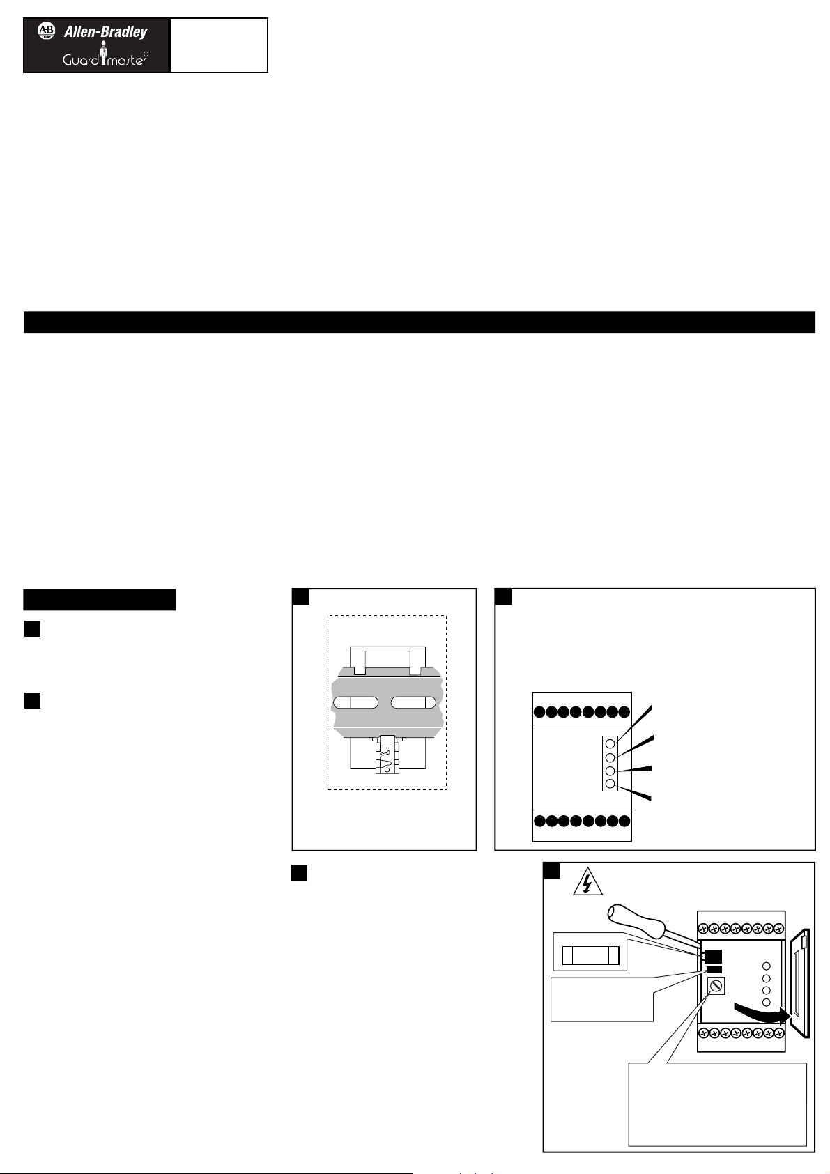
(a) Wiring diagrams
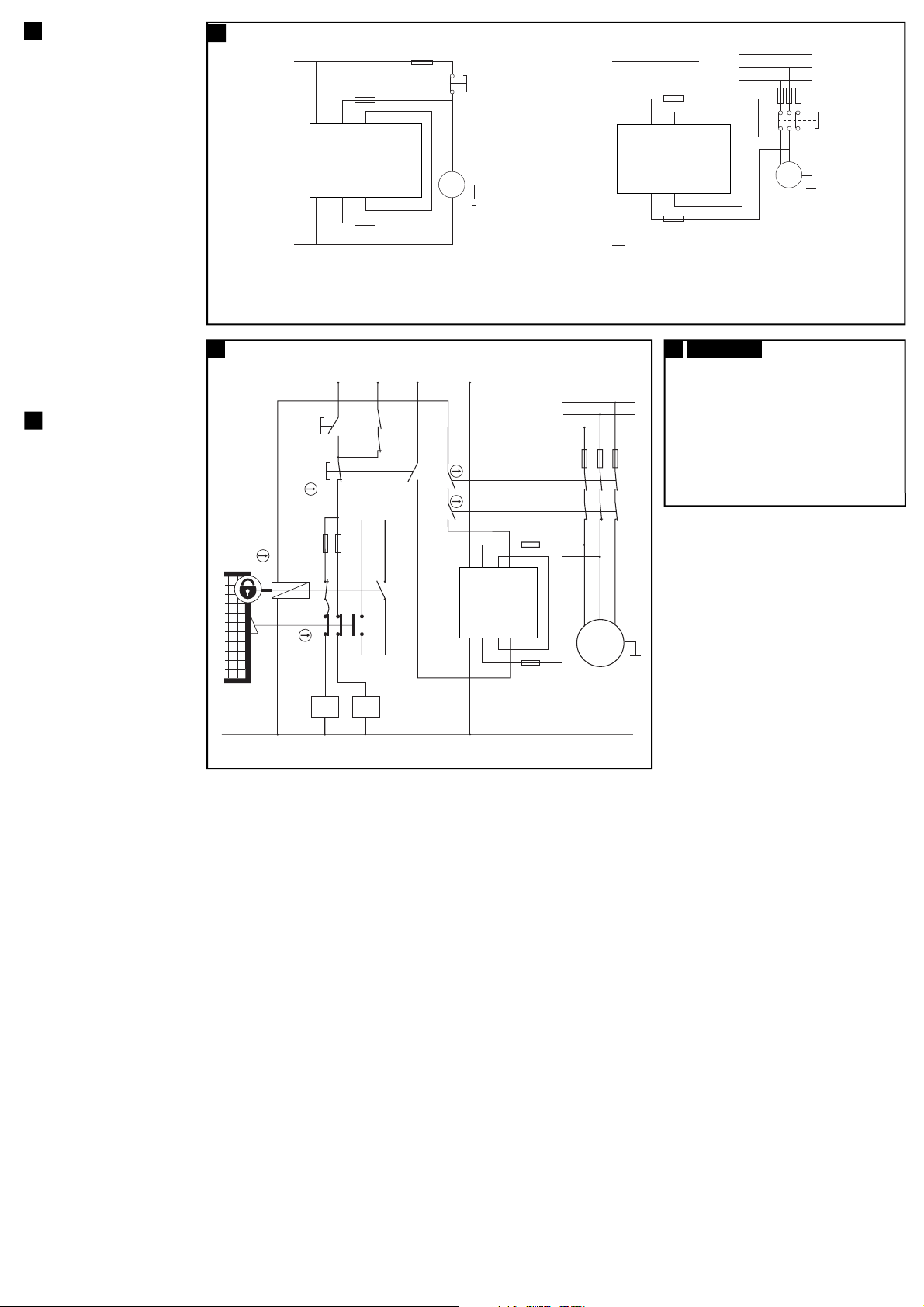
(a) Application example/Anwendungsbeispiel/ Exemple d’application
FUSE 500mA
FUSE 500mA
(a) Verkabelungsschemata
Schémas de câblage
(b) SICHERUNG, 500mA /
Fusible 500mA.
(c) CU3 Steuergerät /
Détecteur CU3.
(d) Der CU2 überwacht die Verbindung zum
Motor über die Anschlüsse Z1-Z2. Eine
Unterbrechung im Z1-Z2 Kreis wird
festgestellt und verhindert, daß die
Sicherheits-Ausgangs-Kontakte 13-14 &
23-24 schließen wenn der Motor läuft
oder angehalten ist. Wieder herstellen
der CU3 Funktion: Spannung abschalten,
Fehler beseitigen im Z1-Z2 Kreis und
Spannung wieder einschalten. Korrekte
Funktion überprüfen.
Le relais de sécurité CU3 contrôle les
connexions vers le moteur via les bornes
Z1-Z2. Toute ouverture de circuit sur la
boucle Z1-Z2 sera détectée et empêchera la
fermeture des contacts de sécurité 13-14 &
23-24 que le moteur soit en marche ou
arrêté. Pour récupérer le bon
fonctionnement du CU3 : Couper toute
alimentation, réparer la panne sur la boucle
Z1-Z2 et remettre en énergie. Contrôler le
bon fonctionnement.
4
(b)
(b)
(b)
(b)
(c)
(c)
(b) START DRUCKTASTER
Bouton-poussoir à impulsion
(c) K1/K2 (HILFSKONTAKT)
K1 (AUX)
(d) STOP EINRASTENDER DRUCKTASTER
Bouton d’arrêt à accrochage
(e) GUARDMASTER TLS-GD2: TLS1
magnetspulenbetätigter Sperrschalter
GUARDMASTER TLS-GD2: TLS1
Gâche électromagnétique
(f) SICHERUNGEN /
Fusible
(g) MAGNETSPULE /
Solénoïde
(h) SCHUTZTÜR GESCHLOSSEN
Protecteur fermé
(i) HILFSSTROMKREIS
(KONTAKTSTATUSANZEIGE)
Circuit auxiliaire
(Indication d'état des contacts)
(j) HILFSSTROMKREIS
(SPERRSTATUSANZEIGE)
Circuit auxiliaire
(Indication de vérrouillage)
(k) CU3 Steuergerät /
Détecteur CU3
5
(b)
(c)
(d)
(e)
(k)
(f)
(h)
(g)
(i)
(j)
(d)
The CU3 monitors the connections to the motor via the Z1-Z2 terminals. A break in the Z1-Z2 loop will be detected and the safety output contacts 13-14 &
23-24 will be pevented from closing when the motor is either running or stopped. To restore the CU3 function: isolate all power, repair the fault in the Z1-Z2 loop
and reinstate power. Check for correct operation.
Connect CU3 as shown in these instructions and to appropriate
standards requirement.
DO NOT EARTH (GROUND) 24V DC SUPPLY TO THE CU3.
THIS MAY RESULT IN DAMAGE TO THE CU3.
Note: Under certain conditions the motor supply voltage can
impose on to the 24V supply.
DO NOT EARTH (GROUND) 24V DC SUPPLY TO THE CU3. THIS MAY RESULT IN DAMAGE TO THE CU3.
DO NOT EARTH (GROUND) 24V DC SUPPLY TO THE CU3. THIS MAY RESULT IN DAMAGE TO THE CU3.
Page 3

INSPEKTION UND WARTUNG
(d) INSPECTION & MAINTENANCE
INSPECTIONS ET ENTRETIEN
At least every 6 months
Isolate all power! Check terminal connection tightness and check
wiring for signs of damage. Check LED's are operating correctly.
Au minimum une fois tous les 6 mois
Couper l’alimentation. Vérifier que les connexions des bornes sont
serrées; examiner le câblage pour relever tout endommagement
éventuel. Vérifier que les voyants fonctionnent correctement.
Mindestens alle 6 Monate:
Sämtliche Spannungsversorgungen trennen! Klemmenanschlüse auf
sichere Verbindung, und alle Kabel auf Beschädigungen überprüfen.
Korrekte Funktion der LED prüfen.
REPARATUR
(e) REPAIR
RÉPARATIONS
Repair is limited to the internal replaceable fuse.
If there is any malfunction or damage, no attempts should be made to
repair it. The unit should be replaced before machine operation is
allowed.
DO NOT DISMANTLE THE UNIT.
Les réparations se limitent au remplacement du fusible interne. Dans
l’éventualité d’un problème technique ou d’une détérioration de cet
appareil ne jamais procéder à la réparation soi-même. L’appareil doit
être remplacé immédiatement avant la remise en production de la
machine.
DANS TOUS LES CAS, NE DISLOQUEZ PAS L'APPAREIL.
Der zulässige Reparaturumfang ist auf das Auswechseln der einbauten
Sicherung beschränkt. Bei eventuellen Fehlfunktionen oder Schäden
niemals den Versuch einer eigenständigen Reparatur unternehmen.
Das Gerät sollte vor erneuter Inbetriebnahme der Maschine
ausgetauscht werden.
DAS GERÄT NIEMALS ZERLEGEN!
(f) Technical Specifications
Conforming to standards EN60204, EN954-1, EN292.
Power supply 24 VAC/DC, 110 VAC or 230 VAC.
Power consumption < 4 VA.
X1-X2 Contactor monitor loop N/C contactor loop.
Inputs Z1-Z2 (NOTE: each input is to be fused
externally with 500mA fuse, see wiring
diagram at step 4).
Internal fuse 500 mAT Replaceable supply fuse.
Internal adjustment The motor sensitivity can be altered by
the variable resistor (step 3).
Relay outputs 2 N/O and 1 N/C TUV approved.
Utilisation Cat. AC15 4 A / 250 VAC / 1000 VA at COSØ=1.
DC13 2 A / 30 VDC / 60 W.
Min. switched current / voltage 10 mA / 10 V.
Max. output fuse 5 A Quick acting.
Indication LED 1 Red 1 = Power On.
LED 2 Green = Motor stopped.
LED 3 Yellow = Fault.
LED 4 Red 2 = Motor running.
Maximum motor voltage 500 VAC.
Detection threshold 0.5 V.
Impulse withstand voltage 2500 V.
Operating temperature -10°C to +55°C.
Contamination level 3.
Humidity 90% at +50°C.
Degree of enclosure protection IP 40 DIN 0470.
Terminal isolation IP 20 DIN 0470.
Max. conductor size 1 x 2.5mm2 stranded with sleeves
stripped 8mm, 1 x 4 mm2 solid conductor.
Terminals Plus-minus terminals screws M3.5 box
terminal with wire protection.
Housing 16 Way D=120 H=73 W=45.5mm.
Weight 510g.
Material and colour Polycarbonate, red .
Installation group C in accordance with VDE 0110.
Fixing details 35mm DIN rail.
Spécifications TechniquesTechnische Daten
120
35mm DIN rail mounting
45
73
Konformität mit folgenden Normen: EN 60204, EN 954-1, EN 292
Leistungsversorgung 24 V AC/DC, 110 V AC oder 230 V AC
Leistungsaufnahme < 4 VA
X1-X2 Schütz-Überwachungsschlaufe Ruhekontakt-Schützschlaufe
Eingänge Z1-Z2 (ANMERKUNG: jeder Eingang ist
extern durch eine 500mA-Sicherung zu
schützen (siehe Kabelschema für Schritt 4).
Eingebaute Sicherung 500 mAT (auswechselbar)
Interne Justierung Änderung der Motorempfindlichkeit
durch Stellwiderstand (Schritt 3)
Relaisausgänge 2 Arbeitskontakte, 1 Ruhekontakt, mit
TÜV-Zulassung
Anwendungsklasse AC15 4 A / 250 V AC / 100 VA bei COSΩ=1
DC13 2 A / 30 V DC / 60 W
Min. Schaltstrom / Schaltspannung 10 mA / 10 V
Max. Ausgangssicherung Flinke Sicherung, 5 A
Anzeigen LED 1 Rot = Strom EIN
LED 2 Grün = Motor-Stillstand
LED 3 Gelb = Fehler
LED 4 Rot = Motor dreht
Max. Motorspannung 500 V AC
Erfassungsschwelle 0,5 V
Bemessungs-Stoßspannung 2500 V
Betriebstemperaturbereich -10 °C bis +50 °C
Kontaminationsklasse 3
Feuchtigkeit 90% bei +50 °C
Einbaugehäuse-Schutzklasse IP 40, DIN 0470
Klemmenisolierung IP 20, DIN 0470
Max. Leitergröße 1 x 2,5 mm mit Muffen
bloßgelegt 8 mm, 1 x 4 mm Festleiter
Klemmen Plus-Minus-Klemmen Schrauben M3,5
Kastenklemmen mit Kabelschutz
Einbaugehäuse 16-fach, T=120, H=73, B=45,5 mm
Gewicht 510 g
Material und Farbgebung PC, rot
Installationsklasse C, gemäß VDE 0110
Montage Auf 35 mm DIN-Schiene
Conforme aux normes suivantes EN 60204, EN954-1, EN292
Alimentation 24V c.a./c.c., 110V c.a. ou 230 V c.a.
Puissance consommée < 4A
Circuit de contrôle du contacteur X1-X2 Circuit de contacteur N/F
Entrées Z1-Z2 (remarque : chaque entrée doit
être munie d’un fusible externe de 500mA;
voir le schéma de câblage, point 4).
Fusible interne Fusible d’alimentation remplaçable 500 mAT
Réglage interne On peut varier la sensibilité du moteur
avec la résistance variable (3)
Sorties de relais 2 N/O et 1 N/F, homolog. TUV
Cat. d’utilisation AC15 4A / 250V c.a. / 1000 VA à COSØ = 1
DC13 2A / 30 V c.c. / 60 W
Courant/tension commutée maxi 10mA / 10V
Sortie maxi du fusible 5A action rapide
Voyants Voyant 1 Rouge 1 = Sous tension
Voyant 2 Vert = Moteur arrêté
Voyant 3 Jaune = Défaut
Voyant 4 Rouge 2 = Moteur en marche
Tension maximum du moteur 500 V c.a.
Seuil de détection 0,5 V
Tension de régime de l’impulsion 2500 V
Température de service -10ºC à +55ºC
Niveau de contamination 3
Humidité 90% h.r. à +50ºC
Degré de protection du boîtier IP40 DIN 0470
Isolement des bornes IP20 DIN 0470
Dimensions maxi des conducteurs 1 x 2,5 mm toronnés avec gaines
dénudées jusqu’à 8 mm, 1 fil unique de
4 mm
Bornes Bornes filetées M3,5 +/-.
Boîte à bornes avec protection des fils
Boîtier 16 voies Prof.x h. l. = 120 x 73 x 45,5 mm
Poids 510 grammes
Matériau et couleur Polycarbonate, rouge
Groupe d’installation C conf. à VDE0110
Fixation Rail DIN de 35 mm
2
2
Montage auf 35 mm DIN-Schiene
2
2
Montage sur rail DIN 35mm
(g)
Isolate
before opening
Made in the UK
POWER
RUN
FAULT
STOP
A2 • Z2 • X2 14 24 32
A1
•
Z1 • X1 13 23 31
SEE SIDE
FOR SUPPLY
CU3
ZERO SPEED
CONTROL UNIT
R
EN60204-1,
EN 292, EN 954-1
Page 4

Drg No: 70902 / Issue No: 3
EO: 26481
R
 Loading...