

Page 1

User Manual
Guardmaster® EtherNet/IP Network Interface
Catalog Numbers 440R-ENETR
Page 2
Important User Information
IMPORTANT
Read this document and the documents listed in the additional resources section about installation, configuration, and
operation of this equipment before you install, configure, operate, or maintain this product. Users are required to
familiarize themselves with installation and wiring instructions in addition to requirements of all applicable codes, laws,
and standards.
Activities including installation, adjustments, putting into service, use, assembly, disassembly, and maintenance are required
to be carried out by suitably trained personnel in accordance with applicable code of practice.
If this equipment is used in a manner not specified by the manufacturer, the protection provided by the equipment may be
impaired.
In no event will Rockwell Automation, Inc. be responsible or liable for indirect or consequential damages resulting from the
use or application of this equipment.
The examples and diagrams in this manual are included solely for illustrative purposes. Because of the many variables and
requirements associated with any particular installation, Rockwell Automation, Inc. cannot assume responsibility or
liability for actual use based on the examples and diagrams.
No patent liability is assumed by Rockwell Automation, Inc. with respect to use of information, circuits, equipment, or
software described in this manual.
Reproduction of the contents of this manual, in whole or in part, without written permission of Rockwell Automation,
Inc., is prohibited.
Throughout this manual, when necessary, we use notes to make you aware of safety considerations.
WARNING: Identifies information about practices or circumstances that can cause an explosion in a hazardous environment,
which may lead to personal injury or death, property damage, or economic loss.
ATTENTION: Identifies information about practices or circumstances that can lead to personal injury or death, property
damage, or economic loss. Attentions help you identify a hazard, avoid a hazard, and recognize the consequence.
Identifies information that is critical for successful application and understanding of the product.
Labels may also be on or inside the equipment to provide specific precautions.
SHOCK HAZARD: Labels may be on or inside the equipment, for example, a drive or motor, to alert people that dangerous
voltage may be present.
BURN HAZARD: Labels may be on or inside the equipment, for example, a drive or motor, to alert people that surfaces may
reach dangerous temperatures.
ARC FLASH HAZARD: Labels may be on or inside the equipment, for example, a motor control center, to alert people to
potential Arc Flash. Arc Flash will cause severe injury or death. Wear proper Personal Protective Equipment (PPE). Follow ALL
Regulatory requirements for safe work practices and for Personal Protective Equipment (PPE).
Allen-Bradley, ControlLogix, CompactLogix, Guardmaster, SoftLogix, Rockwell Software, Rockwell Automation, RSLogix, RSLinx, and TechConnect are trademarks of Rockwell Automation, Inc.
Trademarks not belonging to Rockwell Automation are property of their respective companies.
Page 3
Preface
Read this preface to familiarize yourself with the rest of the manual. It provides
information concerning:
• who should use this manual
• the purpose of this manual
• related documentation
• conventions used in this manual
Who Should Use this Manual
Use this manual if you are responsible for designing, installing, programming, or
troubleshooting control systems that use the 440R-ENETR Guardmaster®
EtherNet/IP network interface.
Purpose of this Manual
This manual is a reference guide for the 440R-ENETR Guardmaster
EtherNet/IP network interface, communications interface for Guardmaster
Safety Relays. It describes the procedures you use to install, wire, configure,
troubleshoot, and use these modules.
ATT ENTI ON: You must use firmware version 2 or later Guardmaster
Safety Relays equipped with the optical bus with the interface.
Firmware version 1 Guardmaster Safety Relays do not work with the
interface.
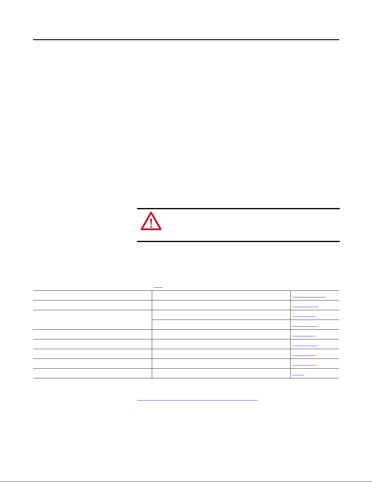
Additional Resources
These documents contain additional information concerning related products
from Rockwell Automation.
For Information About See This Publication Publication Number
Next Generation Safety Relays (GSR) Next Generation Safety Relays Overview Brochure EUSAFE-BR009A
Using EtherNet/IP for industrial control EtherNet/IP Design Considerations Reference Manual ENET-RM002
ControlLogix Ethernet communication interface modules ControlLogix EtherNet/IP Bridge Module Installation Instructions 1756-IN019
EtherNet/IP Modules in Logix5000 Control Systems User Manual ENET-UM001
ControlLogix chassis and power supplies installation ControlLogix Chassis and Power Supplies Installation Instructions 1756-IN005
ControlLogix systems ControlLogix System User Manual 1756-UM001
RSLinx RSLinx Classic Getting Results Guide LINX-GR001
440R-ENETR interface installation Guardmaster Ethernet/IP Network Interface Installation Instructions 440R-IN078
Installing an EtherNet/IP network EtherNet/IP Media Planning and Installation Manual ODVA
You can view or download publications at
http:/www.rockwellautomation.com/literature/
. To order paper copies of
technical documentation, contact your local Allen-Bradley distributor or
Rockwell Automation sales representative.
Rockwell Automation Publication 440R-UM009B-EN-P - February 2014 3
Page 4

Preface
Common Techniques Used in this Manual
The following conventions are used throughout this manual:
• Bulleted lists such as this one provide information, not procedural steps.
• Numbered lists provide sequential steps or hierarchical information.
• Italic type is used for emphasis.
Rockwell Software products contain extensive tutorials and help screens. We
recommend that you use these tutorials and help screens to learn about the
products.
For more information about Rockwell Software products, visit the Rockwell
Software website at
http://www.rockwellautomation.com/software/.
4 Rockwell Automation Publication 440R-UM009B-EN-P - February 2014
Page 5

Preface
About the Interface
Table of Contents
Important User Information . . . . . . . . . . . . . . . . . . . . . . . . . . . . . . . . . . . . . . . . 2
Who Should Use this Manual . . . . . . . . . . . . . . . . . . . . . . . . . . . . . . . . . . . . . . . 3
Purpose of this Manual . . . . . . . . . . . . . . . . . . . . . . . . . . . . . . . . . . . . . . . . . . . . . 3
Additional Resources . . . . . . . . . . . . . . . . . . . . . . . . . . . . . . . . . . . . . . . . . . . . . . . 3
Common Techniques Used in this Manual. . . . . . . . . . . . . . . . . . . . . . . . . . . 4
Chapter 1
Overview . . . . . . . . . . . . . . . . . . . . . . . . . . . . . . . . . . . . . . . . . . . . . . . . . . . . . . . . . . 7
Important Interface Considerations . . . . . . . . . . . . . . . . . . . . . . . . . . . . . . . . . 7
About the Interface . . . . . . . . . . . . . . . . . . . . . . . . . . . . . . . . . . . . . . . . . . . . . . . . 8
Power Up a System . . . . . . . . . . . . . . . . . . . . . . . . . . . . . . . . . . . . . . . . . . . . . 8
RIUP Situations. . . . . . . . . . . . . . . . . . . . . . . . . . . . . . . . . . . . . . . . . . . . . . . . 8
Interface Features . . . . . . . . . . . . . . . . . . . . . . . . . . . . . . . . . . . . . . . . . . . . . . . . . . 8
What the Interface Does. . . . . . . . . . . . . . . . . . . . . . . . . . . . . . . . . . . . . . . . . . . . 9
Hardware/Software Compatibility . . . . . . . . . . . . . . . . . . . . . . . . . . . . . . . . . . 9
Use of the Common Industrial Protocol (CIP) . . . . . . . . . . . . . . . . . . . . . 10
Understand the Producer/Consumer Model . . . . . . . . . . . . . . . . . . . . . . . 10
Specify the Requested Packet Interval (RPI) . . . . . . . . . . . . . . . . . . . . . . . . 11
Support of Data Connections . . . . . . . . . . . . . . . . . . . . . . . . . . . . . . . . . . . . . 11
Chapter Summary. . . . . . . . . . . . . . . . . . . . . . . . . . . . . . . . . . . . . . . . . . . . . . . . 11
Install a Guardmaster EtherNet/IP
Network Interface
Configure the Interface for Your
EtherNet/IP Network
Chapter 2
Overview . . . . . . . . . . . . . . . . . . . . . . . . . . . . . . . . . . . . . . . . . . . . . . . . . . . . . . . . 13
Installation Summary. . . . . . . . . . . . . . . . . . . . . . . . . . . . . . . . . . . . . . . . . . . . . 14
Mount the Interface on a DIN Rail . . . . . . . . . . . . . . . . . . . . . . . . . . . . . . . . 15
Wiring Requirements and Recommendations. . . . . . . . . . . . . . . . . . . 16
Grounding Considerations. . . . . . . . . . . . . . . . . . . . . . . . . . . . . . . . . . . . 17
Chapter Summary. . . . . . . . . . . . . . . . . . . . . . . . . . . . . . . . . . . . . . . . . . . . . . . . 17
Chapter 3
Overview . . . . . . . . . . . . . . . . . . . . . . . . . . . . . . . . . . . . . . . . . . . . . . . . . . . . . . . . 19
Configuration Requirements. . . . . . . . . . . . . . . . . . . . . . . . . . . . . . . . . . . . . . 20
IP Address . . . . . . . . . . . . . . . . . . . . . . . . . . . . . . . . . . . . . . . . . . . . . . . . . . . 20
Gateway Address . . . . . . . . . . . . . . . . . . . . . . . . . . . . . . . . . . . . . . . . . . . . . 21
Subnet Mask . . . . . . . . . . . . . . . . . . . . . . . . . . . . . . . . . . . . . . . . . . . . . . . . . 22
Set the Network Address . . . . . . . . . . . . . . . . . . . . . . . . . . . . . . . . . . . . . . . . . 23
Set the Network Address for Guardmaster EtherNet/IP Interface 23
Use the Rockwell BootP/DHCP Utility . . . . . . . . . . . . . . . . . . . . . . . . . . . 24
Save the Relation List . . . . . . . . . . . . . . . . . . . . . . . . . . . . . . . . . . . . . . . . . 26
Use DHCP Software to Configure Your Interface . . . . . . . . . . . . . . . . . . 27
Chapter Summary. . . . . . . . . . . . . . . . . . . . . . . . . . . . . . . . . . . . . . . . . . . . . . . . 27
Rockwell Automation Publication 440R-UM009A-EN-P - February 2014 5
Page 6

Table of Contents
Chapter 4
Automation Controller
Communications
Troubleshoot the Interface
EtherNet/IP Network Interface
Specifications
Interface Web Dialogs
Overview . . . . . . . . . . . . . . . . . . . . . . . . . . . . . . . . . . . . . . . . . . . . . . . . . . . . . . . . 29
Ethernet Messaging. . . . . . . . . . . . . . . . . . . . . . . . . . . . . . . . . . . . . . . . . . . . . . . 29
I/O Messaging . . . . . . . . . . . . . . . . . . . . . . . . . . . . . . . . . . . . . . . . . . . . . . . . . . . 29
Logix Configuration . . . . . . . . . . . . . . . . . . . . . . . . . . . . . . . . . . . . . . . . . . 29
EtherNet/IP Network Configuration with Add-on Profiles . . . . . . 30
Accessing Module Data with Add-on Profiles . . . . . . . . . . . . . . . . . . . 32
Explicit Messaging . . . . . . . . . . . . . . . . . . . . . . . . . . . . . . . . . . . . . . . . . . . . 33
Chapter 5
Overview . . . . . . . . . . . . . . . . . . . . . . . . . . . . . . . . . . . . . . . . . . . . . . . . . . . . . . . . 35
Interpret the Status Indicators . . . . . . . . . . . . . . . . . . . . . . . . . . . . . . . . . . . . . 35
Status Indicators for the Interface . . . . . . . . . . . . . . . . . . . . . . . . . . . . . . 35
Appendix A
Specifications . . . . . . . . . . . . . . . . . . . . . . . . . . . . . . . . . . . . . . . . . . . . . . . . . . . . 37
Appendix B
Work with the Home Page . . . . . . . . . . . . . . . . . . . . . . . . . . . . . . . . . . . . . . . . 39
Work with the Browse LSR Devices Page. . . . . . . . . . . . . . . . . . . . . . . . . . . 41
Work with the Administrative Settings Pages . . . . . . . . . . . . . . . . . . . . . . . 42
Use the Network Configuration Page . . . . . . . . . . . . . . . . . . . . . . . . . . 43
Use the E-mail Configuration Page. . . . . . . . . . . . . . . . . . . . . . . . . . . . . 44
Configure the RSLinx Ethernet
Communication Driver
Tag Definitions
Appendix C
Overview . . . . . . . . . . . . . . . . . . . . . . . . . . . . . . . . . . . . . . . . . . . . . . . . . . . . . . . . 45
Install the RSLinx Software . . . . . . . . . . . . . . . . . . . . . . . . . . . . . . . . . . . . . . . 45
Configure the AB_ETH Driver . . . . . . . . . . . . . . . . . . . . . . . . . . . . . . . . . . . 46
Configure the AB_ETH/IP Driver . . . . . . . . . . . . . . . . . . . . . . . . . . . . . . . . 48
Appendix D
Tag Definitions . . . . . . . . . . . . . . . . . . . . . . . . . . . . . . . . . . . . . . . . . . . . . . . . . . 51
6 Rockwell Automation Publication 440R-UM009A-EN-P - February 2014
Page 7

About the Interface
Chapter 1
Overview
This chapter provides an overview of the Guardmaster EtherNet/IP Network
Interface, its primary features, and how to use it.
You need to understand the concepts discussed in this chapter to configure your
interface and use it in an EtherNet/IP control system.
This table lists where to find specific information.
Top ic Pa ge
Important Interface Considerations 7
About the Interface 8
Power Up a System 8
RIUP Situations 8
Interface Features 8
What the Interface Does 9
Hardware/ Software Compatibility 9
Use of the Common Industrial Protocol (CIP) 10
Understand the Producer/Consumer Model 10
Specify the Requested Packet Interval (RPI) 11
Support of Data Connections 11
Important Interface Considerations
Before you begin using your interface, note the following important
considerations.
ATTENTION: You must use firmware version 2 or later Guardmaster Safety
Relays equipped with the optical bus with the interface. Firmware version 1
Guardmaster Safety Relays do not work with the interface.
Rockwell Automation Publication 440R-UM009B-EN-P - February 2014 7
Page 8

Chapter 1 About the Interface
About the Interface
The Guardmaster EtherNet/IP Network Interface provide connectivity to
EtherNet/IP networks for Guardmaster Safety Relays.
The interface is for the optical bus backplane that provides connectivity through
two RJ-45 connectors for 2-port pass-through support of daisy chain or ring, and
the existing star and tree network topologies.
Power Up a System
Each time the interface is powered up, the adapter compares the number of I/O
modules present on its backplane to the chassis size value from non-volatile
memory. The adapter does not allow any I/O connection until the number of
I/O modules present equals the chassis size value minus one for the adapter itself.
On power up, the interface assigns an address to every Guardmaster Safety Relay
(up to six) in the backplane. The addressing starts from left to right with the
Guardmaster Safety Relay to the immediate right of the interface taking the first
address of 1.
RIUP Situations
Interface Features
You must observe the following rules for Guardmaster Safety Relay system
construction and the
• Actual Guardmaster Safety Relay identification (such as, electronic
keying) is done when connection establishment requests are received from
the controller or controllers. The interface will not allow any I/O
connections until the number and type of Guardmaster Safety Relays
match the configuration in the connection request.
• A Guardmaster Safety Relay removed under power disrupts
communication of the other Guardmaster Safety Relays in the system.
Connections to all safety relays are disallowed until the entire system,
including the interface, is power cycled to initiate re-addressing the system.
• If safety relays of different types are removed and returned to the wrong
locations, attempts to connect to these safety relays will fail during
verification of the electronic ID (providing that keying has not been
disabled).
• If safety relays of the same type are removed and returned to the wrong
locations, they accept connections from the controller or controllers once
they pass their electronic keying check.
Features of the interface include:
• Use of EtherNet/IP messages encapsulated within standard TCP/UDP/
IP protocol
• Common application layer with ControlNet and DeviceNet networks
• Interfacing via Category 5 rated twisted pair cable
removal and reinsertion of safety relays.
8 Rockwell Automation Publication 440R-UM009B-EN-P - February 2014
Page 9
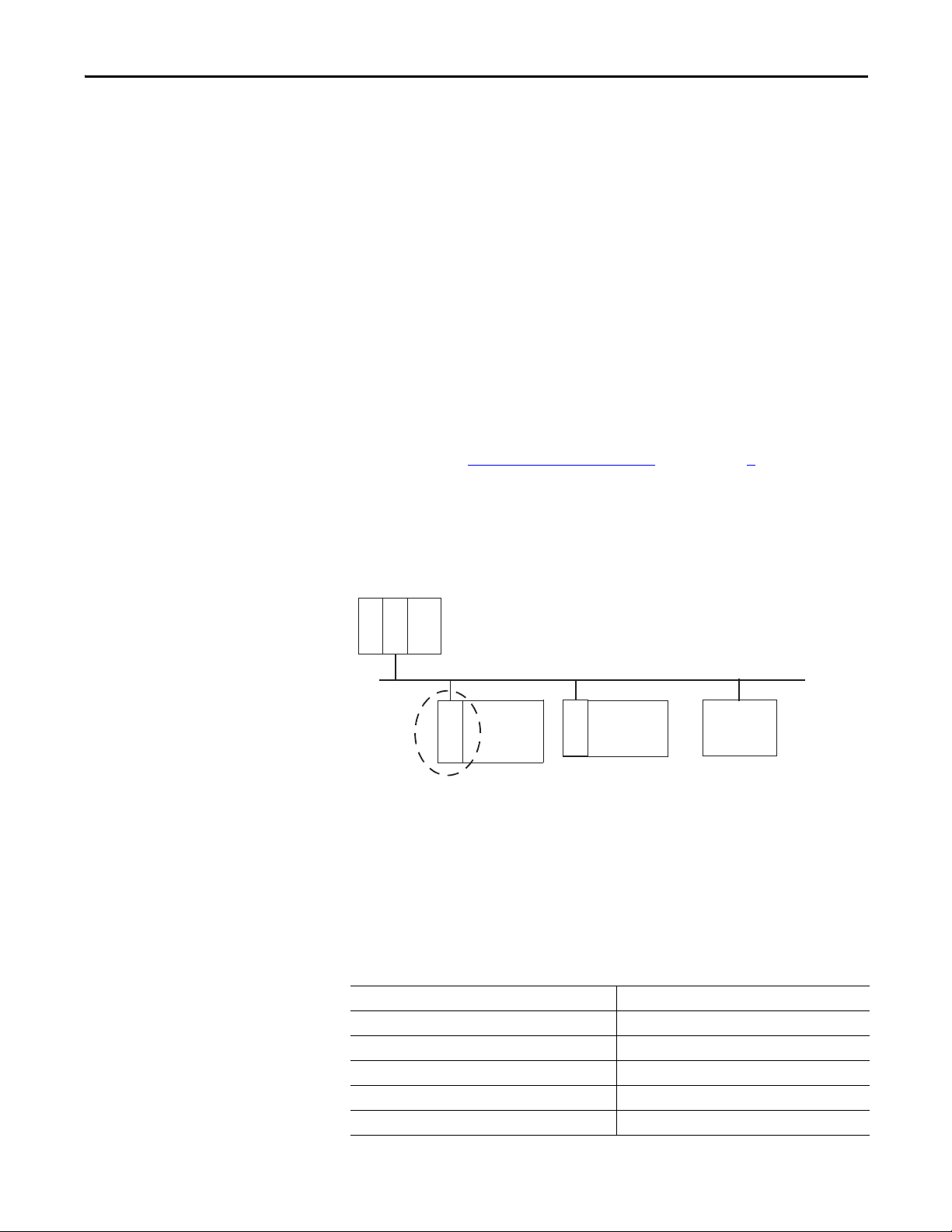
About the Interface Chapter 1
EtherNet/IP Network
Other
Network
Devices
ControlLogix
I/O
Guardmaster
Safety
Relays
L
7
X
E
N
B
T
E
N
E
T
R
E
N
B
T
• Half/full duplex 10 Mbit or 100 Mbit operation
• DIN Rail mounting for 440R-ENETR interface
• Communication from Guardmaster Safety Relays on the same DIN Rail
(mounted immediately to the right of the interface) as the 440R-ENETR
interface (when each safety relay is mounted to the right of the interface
and each unit is within 5 mm of the next) to controllers on the EtherNet/
IP network
• Communication supported by RSLinx® software
• IP address assigned via standard BootP or DHCP tools
• Configuration via RSLogix 5000 software
• No network scheduling required
• No routing tables required
• Support of connections from multiple controllers simultaneously
You must use RSLogix 5000 to configure these features. For more details on
configuration, see Configuration Requirements
on in chapter 3.
What the Interface Does
The interface performs the following primary tasks:
• Real-time input data (also known as implicit messaging) - the interface
serves as a bridge between Guardmaster Safety Relays and the network
• Support of messaging data for programming information (also known as
explicit messaging)
Hardware/Software Compatibility
The interface and the applications described in this manual are compatible with
the following firmware versions and
software releases.
Contact Rockwell Automation if you need software or firmware upgrades to use
this equipment
Product Firmware Revision/ Software Release
440R-ENETR interface 1.xx or later
1756-ENBT 2.3 or later
Logix controller 19 or later
RSLogix 5000 software 19 or later
RSLinx software 2.52 or later
Rockwell Automation Publication 440R-UM009B-EN-P - February 2014 9
Page 10

Chapter 1 About the Interface
Product Firmware Revision/ Software Release
GSR DI (Catalog number 440R-D22R2) 2 or later
GSR DIS (Catalog number 440R-D22S2) 2 or later
GSR EM (Catalog number 440R-EM4R3) 2 or later
GSR EMD (Catalog number 440R-EM4R2D) 2 or later
GSR GLP (Catalog number 440R-GL2S1P) 2 or later
GSR GLT (Catalog number 440R-GL2S2T) 2 or later
Use of the Common Industrial Protocol (CIP)
Understand the Producer/ Consumer Model
The adapter uses the Common Industrial Protocol (CIP). CIP is the application
layer protocol specified for EtherNet/IP, the Ethernet Industrial Protocol, as well
as for ControlNet and DeviceNet networks. It is a message-based protocol that
implements a relative path to send a message from the producing device in a
system to the consuming devices.
The producing device contains the path information that steers the message
along the proper route to reach its consumers. Since the producing device holds
this information, other devices along the path simply pass this information; they
do not store it.
This has the following significant benefits:
• You do not need to configure routing tables in the bridging modules,
which greatly simplifies maintenance and module replacement.
• You maintain full control over the route taken by each message, which
enables you to select alternative paths for the same end device.
The CIP producer and consumer networking model replaces the old source and
destination (master and slave) model. The producer and consumer model reduces
network traffic and increases speed of transmission. In traditional I/O systems,
controllers poll input modules to obtain their input status. In the CIP system,
input modules are not polled by a controller. Instead, they produce (multicast or
unicast) their data either upon a change of state (COS) or periodically.
Multicast is the default mode for version 17 Logix and earlier controllers and
unicast is the default for version 18 with multicast as a selectable option.
The frequency of update depends upon the options chosen during configuration
and where on the network the input module resides. The input module,
therefore, is a producer of input data, and the controller is a consumer of the data.
The controller also produces data for other controllers to consume. The
produced and consumed data is accessible by multiple controllers and other
devices over the EtherNet/IP network. This data exchange conforms to the
producer and consumer model.
10 Rockwell Automation Publication 440R-UM009B-EN-P - February 2014
Page 11

About the Interface Chapter 1
Specify the Requested Packet Interval (RPI)
Support of Data Connections
The Requested Packet Interval or RPI is the update rate specified for a particular
piece of data on the network. The RPI can be specified for the interface and
include all of the Guardmaster Safety Relays in the system.
When you add an interface to the I/O configuration of a controller, you must
enter the RPI as a parameter. This value specifies how often to produce the data
for that device. For example, if you specify an RPI of 50 ms, it means that every
50 ms the device should send its data to the controller and the controller should
send the consumed (output) data to the device.
Use RPIs only for devices that exchange data. For example, a ControlLogix
EtherNet/IP bridge module in the same chassis as the controller does not require
an RPI, because it is not a data-producing member of the system. Its use is only as
a bridge to remote racks.
TheGuardmaster EtherNet/IP Network Interface supports data connections.
A data connection to the interface is a grouping of data from one or more
Guardmaster Safety Relays into a single block of data sent over a single
connection at the same data rate.
Chapter Summary
See the EtherNet/IP Design Considerations Reference Manual,
publicationENET-RM002
In this chapter, you were introduced to the features of the Guardmaster
EtherNet/IP Network Interface, and considerations for installation and usage.
for more information on connections.
Rockwell Automation Publication 440R-UM009B-EN-P - February 2014 11
Page 12

Chapter 1 About the Interface
Notes:
12 Rockwell Automation Publication 440R-UM009B-EN-P - February 2014
Page 13
Install a Guardmaster EtherNet/IP Network Interface
Chapter 2
Overview
This chapter describes how to physically install a Guardmaster EtherNet/IP
network interface; and how to mount the interface to DIN Rail.
This table lists where to find specific information.
Top ic Pag e
Installation Summary 14
Mount the Interface on a DIN Rail 15
Install the Interface 16
Wiring Requirements and Recommendations 16
Grounding Considerations 17
ATTENTION: Environment and Enclosure
This equipment is intended for use in a Pollution Degree 2 industrial
environment, in overvoltage Category II applications (as defined in IEC
60664-1), at altitudes up to 2000 m (6562 ft) without derating.
This equipment is not intended for use in residential environments and may
not provide adequate protection to radio communication services in such
environments.
This equipment is supplied as open-type equipment. It must be mounted
within an enclosure that is suitably designed for those specific environmental
conditions that will be present and appropriately designed to prevent
personal injury resulting from accessibility to live parts. The enclosure must
have suitable flame-retardant properties to prevent or minimize the spread
of flame, complying with a flame spread rating of 5VA or be approved for the
application if nonmetallic. The interior of the enclosure must be accessible
only by the use of a tool. Subsequent sections of this publication may contain
additional information regarding specific enclosure type ratings that are
required to comply with certain product safety certifications.
In addition to this publication, see the following:
• Industrial Automation Wiring and Grounding Guidelines, publication 1770-
4.1, for additional installation requirements
• NEMA 250 and IEC 60529, as applicable, for explanations of the degrees of
protection provided by enclosures
Rockwell Automation Publication 440R-UM009B-EN-P - February 2014 13
Page 14
Chapter 2 Install a Guardmaster EtherNet/IP Network Interface
ATTENTION: Prevent Electrostatic Discharge
This equipment is sensitive to electrostatic discharge, which can cause
internal damage and affect normal operation.
Follow these guidelines when you handle this equipment:
• Touch a grounded object to discharge potential static
• Wear an approved grounding wrist strap
• Do not touch connectors or pins on component boards
• Do not touch circuit components inside the equipment
• Use a static-safe workstation, if available
• Store the equipment in appropriate static-safe packaging when not in use
Installation Summary
Do these steps to install a network interface.
1. Mount the Interface on a DIN Rail.
2. Install the Interface.
SHOCK HAZARD: To prevent electrical shock, disconnect the EtherNet/IP
network interface from it power source before installing or servicing. Install in
suitable enclosure. Keep free from contaminants.
ATTENTION: An incorrectly applied or installed EtherNet/IP network
interface can result in damage to the components or reduction in product
life. Wiring or application errors (e.g. supplying incorrect or inadequate
supply voltage or operating/storing in excessive ambient temperatures) may
result in malfunction of the product.
ATTENTION: Only personnel familiar with the EtherNet/IP network interface
and associated machinery should plan to install, set up, and maintain the
system. Failure to comply may result in personal injury and/or equipment
damage.
ATTENTION: This is a Class A product. In a domestic environment, this
product may cause radio interference in which case the user may be required
to take adequate measures.
14 Rockwell Automation Publication 440R-UM009B-EN-P - February 2014
Page 15
Install a Guardmaster EtherNet/IP Network Interface Chapter 2
5
1
2
3
4
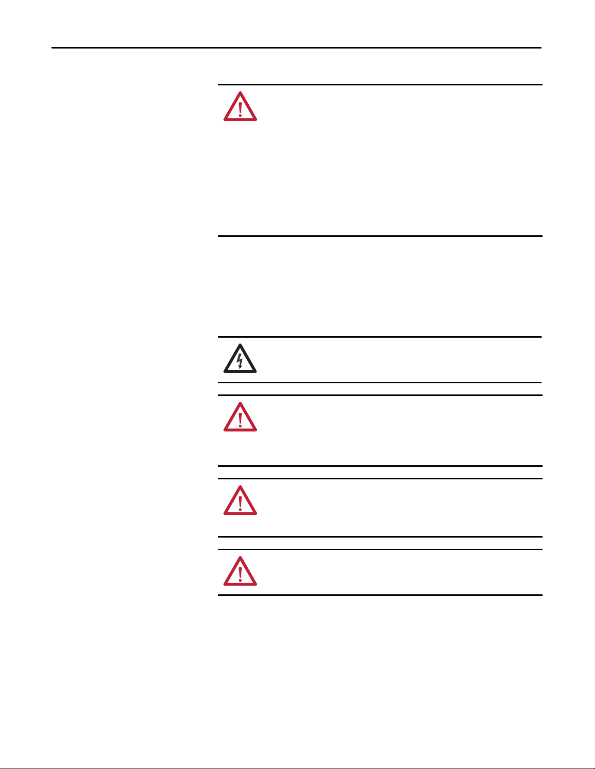
Use the figure to identify the external features of your interface.
Figure 1 - Physical Features of the 440R-ENETR Interface
Description Description
1 Removable terminal block 4 Network address rotary switches
2 Status indicators 5 Ethernet network RJ-45 connectors
3 Optical communications link
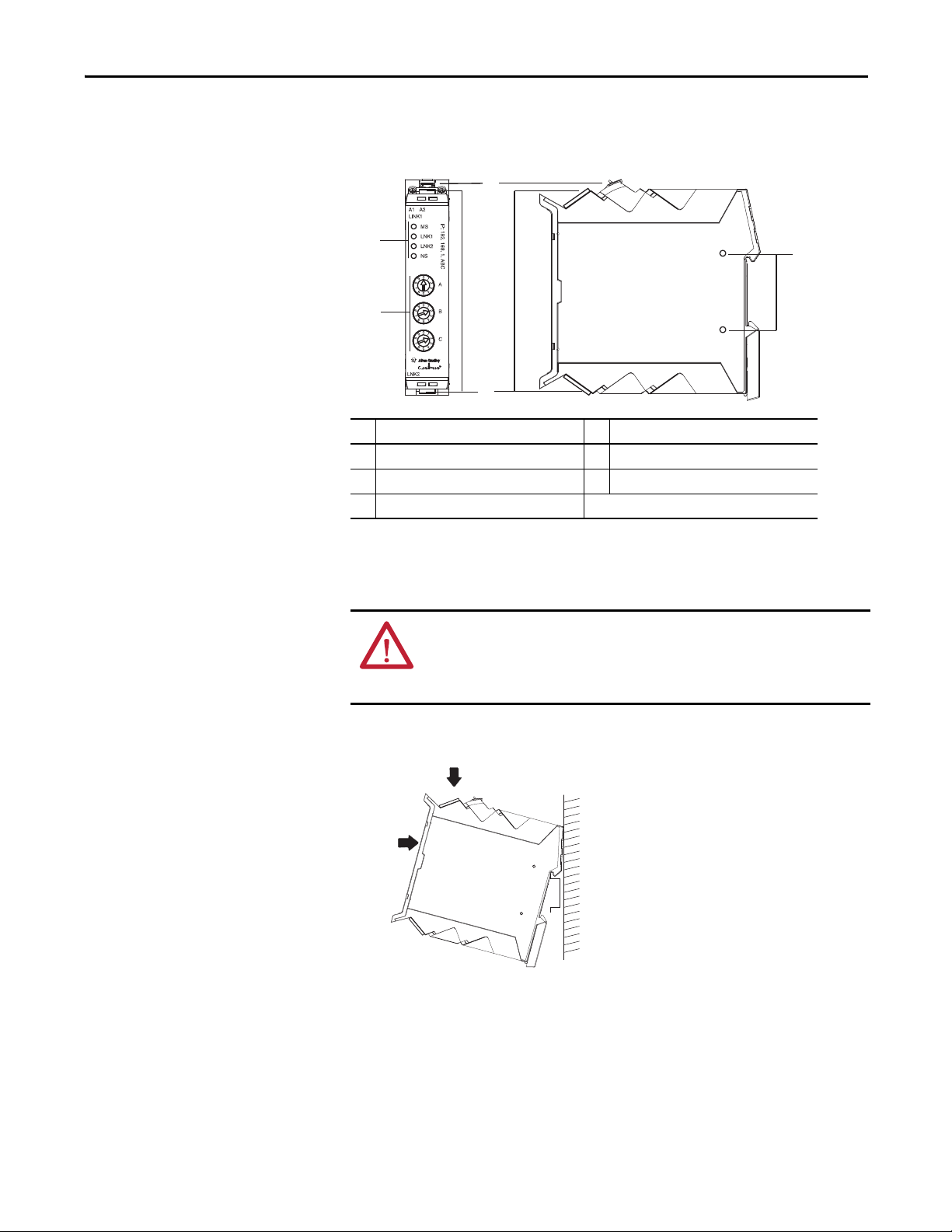
Mount the Interface on a DIN Rail
Follow these steps to mount the interface on a DIN Rail.
ATTENTION: To avoid overheating, the unit must be mounted vertically and
requires 37.4mm (1.5in.) of clearance at the top and the bottom to allow
adequate ventilation. The temperature ratings for the unit will be derated if
not mounted in this manner.
1. Position the adapter vertically above an IEC standard (35x7.5x1 mm) tophat DIN Rail at a slight angle (DIN Rail: Cat. No. 199-DR1; 46277-3).
2. Press down firmly to install the interface on the DIN Rail.
3. Set the network address switches to the desired value. See Set the Network
Address in chapter 3 for more details on setting the IP address.
To remove your interface from the DIN Rail, pry the DIN Rail latch downwards
until there is separation from the latch and the DIN Rail.
Rockwell Automation Publication 440R-UM009B-EN-P - February 2014 15
Page 16
Chapter 2 Install a Guardmaster EtherNet/IP Network Interface
Install the Interface
Install the interface to the left of Guardmaster Safety Relays equipped with an
optical communication bus. There must be no more than 5 mm horizontal
separation between two adjacent relays for the optical communication bus to
operate properly.
Wiring Requirements and Recommendations
• Allow for at least 50 mm (2 in.) between I/O wiring ducts or terminal
strips and the interface.
• Separate wiring by signal type. Bundle wiring with similar electrical
characteristics together.
• Label wiring to all devices in the system. Use tape, shrink-tubing, or other
dependable means for labeling purposes. In addition to labeling, use
colored insulation to identify wiring based on signal characteristics. For
example, you may use blue for DC wiring and red for AC wiring.
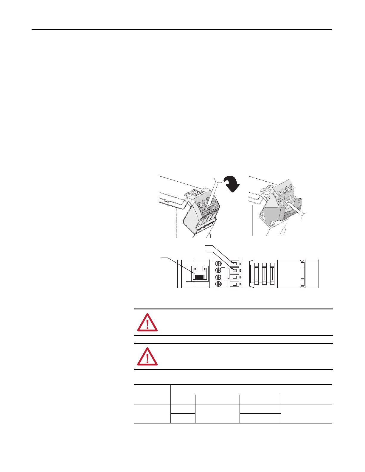
Refer to the following illustration to wire the interface.
A1 = Supply
Ethernet
RJ-45
connector
A2 = Common
ATTENTION: Do not connect 120/240V AC power to the A1/A2 DC supply.
ATTENTION: Do not wire more than two conductors on any single terminal.
Table 1 - Wire Requirements
Type Min Max
440R- ENETR
Solid 0.14 mm2 (26 AWG) 2.5 mm2 (14 AWG) Rated @ 90 ºC (194 ºF)
Stranded 1.5 mm
TOP VIEW
Wire Size
2
(16 AWG)
insulation max
16 Rockwell Automation Publication 440R-UM009B-EN-P - February 2014
Page 17

Install a Guardmaster EtherNet/IP Network Interface Chapter 2
Grounding Considerations
The grounding and bonding must be of equal potential between all devices in the
communication coverage area.
ATTENTION: If this equipment is used in a manner not specified by the
manufacturer, the protection provided by the equipment may be impaired.
Chapter Summary
In this chapter, you learned how to install and wire your Guardmaster EtherNet/
IP network interface. The following chapter describes how to configure your
Guardmaster EtherNet/IP network interface to communicate on the EtherNet/
IP network by providing an IP address, gateway address, and Subnet mask.
Rockwell Automation Publication 440R-UM009B-EN-P - February 2014 17
Page 18

Chapter 2 Install a Guardmaster EtherNet/IP Network Interface
Notes:
18 Rockwell Automation Publication 440R-UM009B-EN-P - February 2014
Page 19

Chapter 3
Configure the Interface for Your EtherNet/ IP Network
Overview
Before using your interface in an EtherNet/IP network, you need to configure it
with an IP address, subnet mask, and optional Gateway address. This chapter
describes these configuration requirements and the procedures for providing
them. Here are ways you can do this:
• Use the Rockwell BootP/DHCP utility, version 2.3 or later, that ships
with RSLogix 5000 or RSLinx software.
– You can also use this utility to reconfigure a device with an IP address
you must change.
• Use a
• Use the Network Address rotary switches.
• Have your network administrator configure the interface via the network
See the table for a list of where to find information in this chapter.
Top ic Pa ge
Configuration Requirements 20
IP Address 20
Gateway Address 21
Subnet Mask 22
Set the Network Address 23
Set the Network Address for Guardmaster EtherNet/IP Interface 23
Use the Rockwell BootP/DHCP Utility 24
Save the Relation List 26
Use DHCP Software to Configure Your Interface 27
third party DHCP server.
DHCP server.
Rockwell Automation Publication 440R-UM009B-EN-P - February 2014 19
Page 20
Chapter 3 Configure the Interface for Your EtherNet/IP Network
Class A
Class B
Class C
Network ID
Host ID
Host ID
Host ID
0
0
0
10
0
110
78
15 16
31
31
3123 24
Network ID
Network ID
EXAMPLE
Configuration Requirements
Before you can use your interface, you must configure its IP address, its subnet
mask, and, optionally, a gateway address. You can use the Rockwell BootP utility,
version 2.3 or later, to perform the
configuration. You can also use a DHCP
server or the network address switches to configure these parameters.
ATTENTION: You must use firmware version 2 or later Guardmaster Safety
Relays equipped with the optical bus with the interface. Firmware version 1
Guardmaster Safety Relays do not work with the interface.
If you need to reset the interface to factory defaults, set the network address
rotary switches to 888 and perform a power cycle to the device.
IP Address
The IP address identifies each node on the IP network (or system of connected
networks). Each TCP/IP node on a network (including the interface) must have
a unique IP address.
The IP address is 32 bits long and has a Network ID part and Host ID part.
Networks are classified A, B, C, (or other). The class of the network determines
how an IP address is formatted
.
You can distinguish the class of the IP address from the first integer in its dotteddecimal IP address as follows:
Range of first integer Class Range of first integer Class
0 1…127 A 192…223 C
128…191 B 224… 255 other
Each node on the same physical network must have an IP address of the same
class and must have the same network ID. Each node on the same network must
have a different Host ID thus giving it a unique IP address.
IP addresses are written as four decimal integers (0…255) separated by periods
where each integer gives the value of one byte of the IP address
For example, the 32-bit IP address:
10000000 00000001 00000000 00000001 is written as
128.1.0.1
20 Rockwell Automation Publication 440R-UM009B-EN-P - February 2014
.
Page 21

Configure the Interface for Your EtherNet/IP Network Chapter 3
Network 1
Network 2
128.1.0.1
128.2.0.1 128.2.0.2 128.2.0.3
128.1.0.2
A
B
G
C
Gateway Address
This section applies to multi-network systems. If you have a single network
system, refer to the next section.
The Gateway Address is the default address of a network. It provides a single
domain name and point of entry to the site. Gateways connect individual physical
networks into a system of networks.
When a node needs to communicate with a node on another network, a gateway
transfers the data between the two networks. The figure shows gateway G
connecting Network 1 with Network 2.
When host B with IP address 128.2.0.1 communicates with host C, it knows
from C’s IP address that C is on the same network. in an Ethernet environment,
B can then resolve C’s IP address into a hardware address (MAC address) and
communicate with C directly.
When host B communicates with host A, it knows from A’s IP address that A is
on another network (the network IDs are different). In order to send data to A, B
must use the IP address of the gateway connecting the two networks. In this
example, the gateway’s IP address on Network 2 is 128.2.0.3.
The gateway has two IP addresses (128.1.0.2 and 128.2.0.3). The first must be
used by hosts on Network 1 and the second must be used by hosts on Network 2.
To be usable, a gateway of a host must be addressed using a network ID matching
its own.
Rockwell Automation Publication 440R-UM009B-EN-P - February 2014 21
Page 22

Chapter 3 Configure the Interface for Your EtherNet/IP Network
EXAMPLE
These two bits of the Host ID are used to extend the
netdwork ID.
Network 1
Network 2.1
Network 2.2
A
BC
DE
128.1.0.2
128.1.0.1
128.2.64.3
128.2.128.2
128.2.64.1 128.2.64.2
128.2.128.3
128.2.128.1
G2
G
Subnet Mask
The subnet mask is used for splitting IP networks into a series of subgroups, or
subnets. The mask is a binary pattern that is matched up with the IP address to
turn part of the Host ID address field into a field for subnets
Two bits of the Class B host ID are used to extend the network ID. Each unique
combination of bits in the part of the Host ID where subnet mask bits are 1
specifies a different physical network.
.
Take Network 2 (a Class B network) in the previous
example and add another physical network. Selecting the
following subnet mask would add two additional
network ID bits, allowing for four physical networks:
11111111 11111111 11
000000 00000000 = 255.255.192.0
The new configuration is:
A second network with Hosts D and E was added. Gateway G2 connects
Network 2.1 with Network 2.2.
Hosts D and E will use Gateway G2 to communicate with hosts not on
Network 2.2.
Hosts B and C will use Gateway G to communicate with hosts not on
Network 2.1.
When B is communicating with D, G (the configured Gateway for B) will route
the data from B to D through G2.
22 Rockwell Automation Publication 440R-UM009B-EN-P - February 2014
Page 23

Configure the Interface for Your EtherNet/IP Network Chapter 3
This example shows the network address set
at 163.
Set the Network Address
The interface ships DHCP-enabled and with the switches set to 999. To change
the network address, do the following.
Set the Network Address for Guardmaster EtherNet/IP Interface
• Adjust the switches in front of the module
• Use a Dynamic Host Configuration Protocol (DHCP) server such as
Rockwell Automation BootP/DHCP
• Retrieve the IP address from non-volatile memory
The interface reads the switches first to determine if the switches are set to a valid
number. Set the network address by adjusting the three switches on the front of
the interface.
Figure 2 - Network Address Example
A
0
1
9
8
7
2
3
4
6
5
B
0
1
9
8
7
2
3
4
6
5
0
9
8
7
6
5
Use a small blade screwdriver to rotate the switches. Line up the small notch on
the switch with the number setting you wish to use. Valid settings range from
001…254.
When you use the switches to assign an address and set it to 001, the interface
gateway address is set to 0.0.0.0. and the subnet mask is 255.255.255.0 . When
you use the switches to assign an address and set it to a valid number between
002...254, the interface gateway address is set to 192.168.1.1.
If the switches are set to an invalid number (for example, 000 or a value greater
than 254 excluding 888), the interface checks to see if DHCP is enabled. If
DHCP is enabled, the interface requests an address from a DHCP server. The
DHCP server also assigns other Transport Control Protocol (TCP) parameters.
If DHCP is not enabled, the interface uses the IP address, along with other TCP
configurable parameters, stored in non-volatile memory.
C
1
2
3
4
Rockwell Automation Publication 440R-UM009B-EN-P - February 2014 23
Page 24

Chapter 3 Configure the Interface for Your EtherNet/IP Network
Use the Rockwell BootP/ DHCP Utility
The Rockwell BootP/DHCP utility is a standalone program that incorporates
the functionality of standard BootP software with a user friendly graphical
interface. It is located in the Utils directory on the RSLogix5000 software
installation CD. The interface must have DHCP enabled (factory default and
the network address switches set to an invalid value) to use the utility.
To configure your interface using the BootP utility, perform the following steps:
1. Run the BootP software.
In the BOOTP Request History panel you see the hardware addresses of
devices issuing BootP requests.
24 Rockwell Automation Publication 440R-UM009B-EN-P - February 2014
Page 25

Configure the Interface for Your EtherNet/IP Network Chapter 3
2. Double-click the hardware address of the device you want to configure.
The New Entry dialog appears with the device’s Ethernet Address (MAC).
3. Enter the IP Address you want to assign to the device and click OK. The
device is added to the Relation List, displaying the Ethernet Address
(MAC) and corresponding IP Address, Hostname, and Description (if
applicable).
When the address displays in the IP Address column in the Request History
section, the IP address assignment has been made.
4. To make this configuration static in the device, highlight the device in the
Relation List panel, and click the Disable BOOTP/DHCP button.
When power is cycled to the device, it uses the configuration saved in nonvolatile memory and will not issue a DHCP request.
5. To enable DHCP for a device with DHCP disabled, highlight the device
in the Relation List, and click the Enable DHCP button.
You must have an entry for the device in the Relation List panel to reenable DHCP.
Rockwell Automation Publication 440R-UM009B-EN-P - February 2014 25
Page 26

Chapter 3 Configure the Interface for Your EtherNet/IP Network
Save the Relation List
You can save the Relation List for later use. To save the Relation List, perform the
following steps:
1. Select Save As... from the File menu.
The Save As dialog appears.
2. Select the folder where you want to save the Relation List.
3. Enter a File name for the Relation List, for example, control system
configuration, and click Save.
You can leave the Save as type at the default setting: Bootp Config Files
(*.bpc).
You now have the option to open the file containing the Relation List at a
later session.
26 Rockwell Automation Publication 440R-UM009B-EN-P - February 2014
Page 27

Configure the Interface for Your EtherNet/IP Network Chapter 3
Use DHCP Software to Configure Your Interface
DHCP (Dynamic Host Configuration Protocol) software automatically assigns
IP addresses to client stations logging onto a TCP/IP network.
DHCP is based on BootP and maintains some backward compatibility. The
main difference is that BootP was designed for manual configuration, while
DHCP allows for dynamic allocation of network addresses and configurations to
newly attached devices.
Be cautious about using DHCP software to configure your interface. A DHCP
server typically assigns a finite lease time to the offered IP address.
When 50% of the leased time has expired, the interface attempts to renew its IP
address with the DHCP server.
The possibility exists that the interface will be assigned a different IP address,
which would cause the interface to cease communicating with the ControlLogix
controller.
ATTENTION: To avoid unintended control or loss of control, the interface
must be assigned a fixed IP address. A dynamically provided IP address
should be used only at initial configuration. If a DHCP server is used, it must
be configured to assign the same IP address to your interface.
Failure to observe this precaution may result in unintended machine motion or
loss of process control.
Chapter Summary
This chapter provided instructions on how to configure Guardmaster
EtherNet/IP Interface modules through the RSLogix 5000 software and
included information on configuration requirements and setting the network
address.
Rockwell Automation Publication 440R-UM009B-EN-P - February 2014 27
Page 28

Chapter 3 Configure the Interface for Your EtherNet/IP Network
Notes:
28 Rockwell Automation Publication 440R-UM009B-EN-P - February 2014
Page 29

Automation Controller Communications
Chapter 4
Overview
Ethernet Messaging
This chapter describes and gives examples of how each type of EtherNet/IP
messaging, I/O messaging and Explicit messaging, is used.
Top ic Pag e
Ethernet Messaging
I/O Messaging 29
Logix Configuration 29
EtherNet/IP Network Configuration with Add-on Profiles 30
Accessing Module Data with Add-on Profiles 32
Explicit Messaging 33
The Guardmaster EtherNet/IP network interface supports two types of
EtherNet/IP messaging.
• I/O Messaging – Used for deterministic EtherNet/IP communications
with ControlLogix®, CompactLogix™, SoftLogix™, and EtherNet/IP
scanners. Its primary use is to read and write I/O data for control purposes.
• Logic Explicit Messaging – Used for non-deterministic communications
in which data is not critical for control. Logic explicit messages have a
lower priority compared to I/O messages and are used to read and write
non-critical data.
29
I/O Messaging
RSLogix™ 5000 software is used to configure I/O messaging between an
automation controller and a Guardmaster EtherNet/IP network interface on an
EtherNet/IP network.
The following example provides the steps necessary to configure a Logix
controller for I/O messaging.
Logix Configuration
An Add-on Profile is available for the Guardmaster EtherNet/IP network
inferface and can be used with RSLogix 5000 version 19 and higher. The profile
can be downloaded from:
http://support.rockwellautomation.com/controlflash/LogixProfiler.asp
Rockwell Automation Publication 440R-UM009B-EN-P - February 2014 29
Page 30

Chapter 4 Automation Controller Communications
An existing project can be used or a new project can be created to configure
EtherNet/IP I/O messaging. To create a new project, perform the following
steps.
1. Select File > New from the RSLogix 5000 menu bar.
2. Select the controller type. Then, enter a name for the project and click
Next.
3. Select the Security Authority and enter a description. Then, click Finish.
EtherNet/IP Network Configuration with Add-on Profiles
After the controller configuration, the Guardmaster EtherNet/IP Network
Interface has to be added to the I/O Configuration.
1. Right-click on the EtherNet/IP bridge within the I/O Configuration
folder, then select New Module to open the Select Module Type window
30 Rockwell Automation Publication 440R-UM009B-EN-P - February 2014
Page 31

Automation Controller Communications Chapter 4
2. Select the 440R-ENETR, then click Create.
3. Enter a name for the Guardmaster EtherNet/IP network interface. The
name will create tags in RSLogix 5000 that can be used to read data from
the Guardmaster Safety Relays being scanned by the Guardmaster
EtherNet/IP network interface.
4. Enter the IP address of the Guardmaster EtherNet/IP network interface.
5. Select Change to configure the Guardmaster safety relays monitored by
the Guardmaster EtherNet/IP network interface.
Rockwell Automation Publication 440R-UM009B-EN-P - February 2014 31
Page 32

Chapter 4 Automation Controller Communications
6. Right-click on an <Empty Slot> in the Module Definition dialog box and
select the Guardmaster Safety Relay that is physically located in that slot
position next to the Guardmaster EtherNet/IP network interface.
Note: Empty slots between Guardmaster Safety Relays are not supported
by the Guardmaster EtherNet/IP network interface at run-time. Your
configuration must represent the actual Safety Relays present beginning
with the first slot and without any empty slots.
7. Once all Guardmaster Safety Relays monitored by the Guardmaster
EtherNet/IP network interface have been added, Click OK.
8. Click OK at the next window to have RSLogix 5000 create the predefined
tags. The Guardmaster EtherNet/IP network interface will now show as a
module in the I/O Configuration folder.
Accessing Module Data with Add-on Profiles
With both the Logix controller and the EtherNet/IP network configured, the
Logix controller can exchange data with the Guardmaster EtherNet/IP network
interface.
1. Open the Controller tags window.
2. Select the Monitor Tags tab.
In the previous example, predefined input tags were created for the GSR
DIS module in slot 1 of the configuration. For detailed information on the
individual tag members and their meaning, see Appendix D
.
32 Rockwell Automation Publication 440R-UM009B-EN-P - February 2014
Page 33

Automation Controller Communications Chapter 4
Explicit Messaging
Data can be accessed from the Guardmaster EtherNet/IP network interface by
non-Logix automation controllers that support EtherNet/IP explicit messaging.
This example shows the configuration of an explicit message from a MicroLogix™
1100 controller to the Guardmaster EtherNet/IP network interface:
1. Set up the MSG instruction to read the data assembly from the
Guardmaster EtherNet/IP network interface by configuring the following
fields.
– Channel: 1 (Integral) (this is the Ethernet port)
– Communication Command: CIP Generic
– Data Table Address (Receive): N7:0 (choose an address that supports
60 bytes)
– Size in Bytes (Receive): 60
– Extended Routing Info File(RIX): RIX10:0
– Service: Read Assembly
– Class: 04
– Instance: 100 (64h)
– Attribute: 03
2. Set the Ethernet network address of the Guardmaster EtherNet/IP
network interface as the target of the message instruction:
Appendix D
describes the individual members of the data returned from
the message instruction.
Rockwell Automation Publication 440R-UM009B-EN-P - February 2014 33
Page 34

Chapter 4 Automation Controller Communications
Notes:
34 Rockwell Automation Publication 440R-UM009B-EN-P - February 2014
Page 35

Troubleshoot the Interface
Module Status
Link 1 Activity/Status
Network Status
Link 2 Activity/Status
Chapter 5
Overview
Interpret the Status Indicators
This chapter describes the different status indicators available in the Guardmaster
EtherNet/IP network interface and how to interpret these indicators to help
troubleshoot the module.
The following table lists where to find specific information
Top ic Pa ge
Interpret the Status Indicators
Status Indicators for the Interface 35
Read this chapter to learn about what the LED status indicators mean for the
Guardmaster EtherNet/IP Network Interface.
35
Status Indicators for the Interface
The following describes the status indicators on the 440R-ENETR.
Rockwell Automation Publication 440R-UM009B-EN-P - February 2014 35
Page 36

Chapter 5 Troubleshoot the Interface
Table 2 - Status Indicators for 440R-ENETR Interface
Status Description
Module status Off No power applied to device
Solid green Device operating normally
Flashing green Device needs commissioning due to missing, incomplete, or incorrect configuration.
Flashing red/green Module self-test
Flashing red Recoverable fault.
Solid red Unrecoverable fault, may require device replacement.
Network status Off Device is not online
Flashing green Device is online but has no CIP connections in the established state.
Solid green Device online and has CIP connections in the established state.
Flashing red One or more CIP connections in timed-out state.
Solid red Duplicate IP address detected.
Link 1 or Link 2 Activity / Status Off No link established.
Solid green One of the following conditions exist:
Flashing green Transmit or receive activity present on indicated port @ 100 Mbps.
Solid yellow One of the following conditions exist:
Flashing yellow Transmit or receive activity present on indicated port @ 10 Mbps.
Complete firmware update, verify address switches. Check for monitored safety relay fault.
- Device has not completed Dup_MAC_ID test.
- Device not powered - check module status indicator.
Check for Guardmaster safety relay failure and controller operation.
Verify IP address setting and correct, as needed.
• A 100 Mbps (full or half duplex) link exists.
• The ring network is operating normally.
• A 10 Mbps (full or half duplex) link exists.
• The ring network is operating normally.
36 Rockwell Automation Publication 440R-UM009B-EN-P - February 2014
Page 37

Appendix A
EtherNet/IP Network Interface Specifications
Specifications
Following are specifications for the Guardmaster EtherNet/IP Network Interface
Table 3 - General Specifications – Guardmaster EtherNet/IP Network Interface
Specification Description
Indicators 2 red/green status indicators:
Power consumption, max 2.2 W @ 26.4V DC
Power dissipation, max 0.8 W @ 26.4V DC
Thermal dissipation, max 2.7 BTU/hr @ 26.4V DC
Dimensions (HxWxD), approx. 111.4 x 22.5 x 113.6 mm
Enclosure type rating None (open-style)
Terminal base screw torque 0.8 N•m (7 lb•in)
Weight, approx. 180 g (0.4 lb)
Wiring c ategor y
Wire s ize Power connections:
North American temp code T6
IEC temp code T6
(1)
– Module status
– Network status (Ports 1 and 2 combined)
2 green/yellow status indicators:
– Link 1 status
– Link 2 status
(4.39 x 0.89 x 4.47 in.)
1 – on power ports
2 – on communications ports
0.34... 2.1 mm2 (22...14 AWG) solid or stranded copper wire
rated @ 75 °C (167 °F) or greater, 1.2 mm (3/64 in.) insulation max.
Ethernet wiring:
RJ45 connector according to IEC 60603-7, 2 or 4 pair
Category 5e min cable according to TIA 568-B.1 or
Category 5 cable according to ISO/IEC 24702.
(1) Use this conductor category information for planning conductor routing. Refer to publication 1770-IN041, Industrial Automation
Wiring and Grounding Guidelines.
Rockwell Automation Publication 440R-UM009B-EN-P - February 2014 37
Page 38

Appendix A EtherNet/IP Network Interface Specifications
Table 4 - Environmental Specifications
Specification Description
Temperature, operating IEC 60068-2-1 (Test Ad, Operating Cold),
Tem pe rat ure , su rr oun di ng
air, max
Temperature, nonoperating IEC60068-2-1 (Test Ab, Unpackaged Nonoperating Cold)
Relative humidity IEC 60068-2-30 (Test Db, Unpackaged Damp Heat):
Vibration IEC 60068-2-6 (Test Fc, Operating):
Shock, operating IEC60068-2-27 (Test Ea, Unpackaged Shock):
Emissions CISPR 11:
ESD immunity IEC61000-4-2:
Radiated RF immunity IEC 61000-4-3:
EFT/B immunity IEC 61000-4-4:
Surge transient immunity IEC 61000-4-5:
Conducted RF immunity IEC61000-4-6:
IEC 60068-2-2 (Test Bd, Operating Dry Heat),
IEC 60068-2-14 (Test Nb, Operating Thermal Shock):
-20...+55 °C (-4...+131 °F)
55 °C (131 °F)
IEC60068-2-2 (Test Bb, Unpackaged Nonoperating Dry Heat)
IEC60068-2-14 (Test Na, Unpackaged Nonoperating Thermal Shock):
-40...+85 °C (-40...+185 °F)
5...95% non-condensing
5 g @ 10...500 Hz
15 g
Group 1, Class A
6 kV contact discharges
8 kV air discharges
10V/m with 1 kHz sine-wave 80% AM from 80...2000 MHz
10V/m with 200 Hz 50% Pulse 100% AM @ 900 MHz
10V/m with 200 Hz 50% Pulse 100% AM @ 1890 MHz
10V/m with 1 kHz sine-wave 80% AM from 2000...2700 MHz
±4 kV @ 5 kHz on power ports
±2 kV @ 5 kHz on communications ports
±1 kV line-line (DM) and ±2 kV line-earth (CM) on power ports
±2 kV line-earth (CM) on communications ports
10V rms with 1 kHz sine-wave 80% AM from 150 kHz...80 MHz
Table 5 - Certifications
Certifications (when
product is marked)
cULus
(1)
Value
UL Listed Industrial Control Equipment, certified for US and
Canada. See UL File E65584.
CE
European Union 2004/108/EC EMC Directive, compliant with:
EN 61326-1; Meas./Control/Lab., Industrial Requirements
EN 61000-6-2; Industrial Immunity
EN 61000-6-4; Industrial Emissions
EN 61131-2; Programmable Controllers (Clause 8, Zone A & B)
EtherNet/IP
(1) See the Product Certification link at http://www.rockwellautomation.com/products/certification/ for Declaration of Conformity,
Certificates, and other certification details.
38 Rockwell Automation Publication 440R-UM009B-EN-P - February 2014
ODVA conformance tested to EtherNet/IP specifications
Page 39

Appendix
Interface Web Dialogs
.
For Information About Page
Work with the Home Page
Work with the Browse LSR Devices Page 41
Work with the Administrative Settings Pages 42
Use the Network Configuration Page 43
Use the E-mail Configuration Page 44
39
B
Work with the Home Page
Use the interface diagnostics home page to access other interface diagnostics web
pages and see the following information.
• 440R-ENETR
– Revision
– Device IP address
– Ethernet address (MAC)
– Serial number
• Status
– GSR connection status
– GSR faults
– Rotary switch status
– Interface connection status
• Software versions
– EtherNet/IP FW revision
– Controller FW revision
• Configuration
– Switch setting (startup/current)
Rockwell Automation Publication 440R-UM009B-EN-P - February 2014 39
Page 40

Appendix B Interface Web Dialogs
IMPORTANT
Enter the interface IP address
to see the home page.
To display and work with the interface diagnostics home page, follow these
procedures.
Make sure that your PC Internet LAN setting and your TCP/IP
settings are configured to access the subnet on which your
interface communicates.
1. From your web browser, enter the interface IP address to see the Home
page.
2. From the Home page, complete one of these, as desired.
• Click one of the following to access www.ab.com
.
– Allen-Bradley logo at the top of the page
– Visit
ab.com for additional information statement under Resources
• Click Rockwell Automation at the top right to go to
www.rockwellautomation.com
.
• Click the following to see additional diagnostics web pages.
– Browse LSR devices
– Administrative Settings: Network and Email Configuration
40 Rockwell Automation Publication 440R-UM009B-EN-P - February 2014
Page 41

Interface Web Dialogs Appendix B
Work with the Browse LSR Devices Page
To work with the Browse LSR devices options, follow these procedures.
1. From the Home page, click Browse LSR Devices page. The Browse LSR
Devices page opens.
2. In the Refresh Rate field, you can type a refresh rate, noting that the default
rate is 15 seconds.
3. From the Browse LSR devices page, view the following:
• Overview
– Port type/series
– Bus running
– Number of GSR devices found on bus
– Number of GSR devices found on bus
– Error Counters
□ UART framing/parity error
□ UART or receive buffer overrun
□ UART break error
□ Receive timeout error
□ Frame timing error
□ CRC error
□ Unexpected/wrong data received
Rockwell Automation Publication 440R-UM009B-EN-P - February 2014 41
Page 42

Appendix B Interface Web Dialogs
IMPORTANT
• LSR device #N (where N is 1-6 monitored safety relays)
– Device type
– Firmware version
– Running
– Has recoverable fault
– Has non-recoverable fault
– Operation state 1
– Operation state 2
– Recoverable fault processor 1
– Non-recoverable fault processor 1
– Recoverable fault processor 2
– Non-recoverable fault processor 2
– Communication errors
– Communication retries
– Non recoverable error count
– Recoverable error count
Work with the Administrative Settings Pages
To work with the Administrative Settings pages, follow these procedures.
Administrative mode must be enabled to make changes to the
Administrative pages. To enable Administrative mode set the network
address rotary switches to the value 000.
1. From the Home page, click Administrative Settings or Expand to see the
Administrative options, if needed.
2. From the Administrative Settings list, click one of these:
• Network Configuration
• E-mail Configuration
3. Refer to the section of this manual that describes which of these you
clicked: Network Configuration, E-mail Configuration.
42 Rockwell Automation Publication 440R-UM009B-EN-P - February 2014
Page 43

Interface Web Dialogs Appendix B
Use the Network Configuration Page
To use the Network Configuration page to make entries for enabling or disabling
DHCP and setting TCP/IP parameters and Ethernet link operation, follow this
procedure:
1. From the Web page, click the Network Configuration tab at the top of the
page or panel on the left. You see the Network Configuration page.
2. From the Network Configuration tab, complete these entries.
• For Initial Network Configuration DHCP
– Static
– DHCP enabled
• For Network Interface, select form these choices.
– IP Address
– Subnet Mask
– Default Gateway
– Primary Name Server
– Secondary Name Server
– Default Domain Name
– Host Name
• For Ethernet Link, select from these choices
– Ethernet Link Configuration P1
□ Auto
□ 10 HDX
□ 10 FDX
□ 100 HDX
□ 100 FDX
Rockwell Automation Publication 440R-UM009B-EN-P - February 2014 43
Page 44

Appendix B Interface Web Dialogs
– Ethernet Link Configuration P2
□ Auto
□ 10 HDX
□ 10 FDX
□ 100 HDX
□ 100 FDX
Use the E-mail Configuration Page
To use the E-mail Configuration page to configure the interface to send e-mail
messages and text notifications for different communication events, follow this
procedure:
1. From the Web page, click the E-mail Configuration tab at the top of the
page or panel on the left. You see the E-mail Configuration page.
2. From the E-mail Configuration tab, complete these entries.
• For E-mail trig configuration select:
– Send an e-mail message when a non-recoverable fault is reported from
a safety relay
– Send an e-mail message when a recoverable fault is reported from a
safety relay
– Send an e-mail message when there is a safety relay communication
fault
• For E-mail client configuration
– E-mail Recipient
– E-mail Sender
– SMTP Server
– SMTP Username
– SMTP Password
3. Click Apply Changes to save the modified values.
44 Rockwell Automation Publication 440R-UM009B-EN-P - February 2014
Page 45

Configure the RSLinx Ethernet Communication Driver
Appendix
C
Overview
Install the RSLinx Software
To communicate with your adapter over your network, you must configure the
RSLinx Ethernet Communication Driver (AB_ETH) or the EtherNet/IP driver
(AB-ETHIP). You can configure the AB_ETH driver with the IP addresses of all
the Ethernet devices on your system. You need one of these drivers to download
the example application programs in this manual.
See the table for a list of the contents of this appendix.
For Information About Page
Install the RSLinx Software 45
Configure the AB_ETH Driver 46
Configure the AB_ETH/IP Driver 48
Use this procedure to install the RSLinx software on your computer.
1. Insert the CD in the CD-ROM drive.
Note that the CD-ROM supports Windows Autorun. Once inserted into
the CD-ROM drive, if you have Autorun configured, the installation
automatically starts at the first setup screen.
If Autorun is not configured for your CD-ROM drive, go to step 2.
2. From the Start menu, choose Run. The Run dialog opens.
3. Type D:/setup (if it does not appear automatically), where D: is your CD-
ROM drive letter.
4. Click OK.
The progress bar, followed by the welcome screen opens.
Rockwell Automation Publication 440R-UM009B-EN-P - February 2014 45
Page 46

Appendix C Configure the RSLinx Ethernet Communication Driver
Configure the AB_ETH Driver
To configure the AB-ETH Ethernet communication driver perform the
following steps:
1. Start the RSLinx software.
2. From the Communications menu, select Configure Drivers.
3. Select Ethernet Devices from the list and click Add/New...
4. Select the default driver name (for example, AB_ETH-1) or type in a
name and click OK.
The Configure driver dialog opens.
46 Rockwell Automation Publication 440R-UM009B-EN-P - February 2014
Page 47

Configure the RSLinx Ethernet Communication Driver Appendix C
5. Click Add New and enter the IP address or Host Name of your Ethernet
device (for example, 10.88.70.4, Pump1).
6. Repeat step 6 for each additional Ethernet device you need to access.
7. After entering the IP addresses, click Apply.
8. Click OK to close the Configure driver dialog.
The new driver appears in the list of configured drivers. Your list displays
the drivers you configured on your workstation.
9. Close the RSLinx software
.
Rockwell Automation Publication 440R-UM009B-EN-P - February 2014 47
Page 48

Appendix C Configure the RSLinx Ethernet Communication Driver
Configure the AB_ETH/IP Driver
To configure the AB-ETHIP Ethernet communication driver, perform the
following steps.
1. Start the RSLinx software.
2. From the Communications menu, select Configure Drivers.
3. Select EtherNet/IP Devices from the list and click Add/New...
48 Rockwell Automation Publication 440R-UM009B-EN-P - February 2014
Page 49

Configure the RSLinx Ethernet Communication Driver Appendix C
The Configure Driver dialog box opens.
Make sure the Browse Local Subnet button is selected.
The RSLinx software browses your local subnet and automatically reads
the IP address.
4. Click OK.
The AB-ETHIP driver is now configured and appears in the configured
drivers window.
5. Close the RSLinx software
Rockwell Automation Publication 440R-UM009B-EN-P - February 2014 49
.
Page 50

Appendix C Configure the RSLinx Ethernet Communication Driver
Notes:
50 Rockwell Automation Publication 440R-UM009B-EN-P - February 2014
Page 51

Appendix D
Tag Definitions
Table 6 - GSR DI(S) Module Input Tags
Name Data Type Definition
Slotx_GSR_DIS_IN01 BOOL IN01 Status - Indicates whether input circuit 1 is On or Off.
Slotx_GSR_DIS_IN02 BOOL IN02 Status - Indicates whether input circuit 2 is On or Off.
Slotx_GSR_DIS_SingleWireSafetyIn BOOL Single Wire Safety Input Status - Indicates whether the
Slotx_GSR_DIS_ResetRequired BOOL Reset Required Indication - This indication turns On (1)
Slotx_GSR_DIS_CrossLoopOK BOOL Cross Loop OK - Indicates whether the safety relay is
Slotx_GSR_DIS_SafetyOutput BOOL Safety Output Status – Indicates whether the safety
Slotx_GSR_DIS_RecoverableFault BOOL Recoverable Fault Status – Toggles On (1) for one scan
Slotx_GSR_DIS_NonRecoverableFault BOOL Non-Recoverable Fault Status – Toggles On (1) for one
Slotx_GSR_DIS_S12 BOOL S12 Status – Indicates whether terminal S12 of circuit IN01
Slotx_GSR_DIS_S22 BOOL S22 Status – Indicates whether terminal S22 of circuit IN02
Slotx_GSR_DIS_S32 BOOL S32 Status – Indicates whether terminal S32 of circuit IN02
0 = The input channel is Off.
1 = The input channel is On.
0 = The input channel is Off.
1 = The input channel is On.
Single Wire Safety input (L12) is On or Off.
0 = The Single Wire Safety input signal is Off.
1 = The Single Wire Safety input signal is On.
when all monitored input conditions are On and the safety
relay Output is Off (0).
detecting a cross loop fault on one of the input circuits.
0 = Cross loop fault
1 = No fault
output channels are On or Off.
0 = The safety output channels are Off.
1 = The safety input channels are On.
when the safety relay has detected unexpec ted operation of
a monitored safety device. See S12 OpenWire, S22
OpenWire, S32 OpenWire, S42 OpenWire, Cross Loop Fault,
Invalid Switch Setting, and Reset Held On (page 52
details.
0 = No fault
1 = Fault
scan when the safety relay has detected unexpected
internal operation or failed a pulse check. See
NonRecoverableFault_A and NonRecoverableFault_B (page
52) for details.
0 = No fault
1 = Fault
is On or Off.
0 = The terminal is Off.
1 = The terminal is On.
is On or Off.
0 = The terminal is Off.
1 = The terminal is On.
is On or Off.
0 = The terminal is Off.
1 = The terminal is On.
) for
Rockwell Automation Publication 440R-UM009B-EN-P - February 2014 51
Page 52

Appendix D Tag Def ini tio ns
Table 6 - GSR DI(S) Module Input Tags
Name Data Type Definition
Slotx_GSR_DIS_S42 BOOL S42 St atus – Indicates whether terminal S42 of circuit IN02
Slotx_GSR_DIS_L12 BOOL L12 Status – Indicates whether terminal L12 is On or Off.
Slotx_GSR_DIS_S34 BOOL S34 Status – Indicates whether term inal S34 is On or Off.
Slotx_GSR_DIS_NonRecoverableFaul t_A SINT Non-Recoverable Fault Processor A – Indicates a
Slotx_GSR_DIS_NonRecoverableFaul t_B SINT Non-Recoverable Fault Processor B – Indicates a
Slotx_GSR_DIS_S12OpenWire BOOL S12 Open Wire - Indicates S12 open (0) and closed (1)
Slotx_GSR_DIS_S22OpenWire BOOL S22 Open Wire - Indicates S22 open (0) and closed (1)
Slotx_GSR_DIS_S32OpenWire BOOL S32 Open Wire - Indicates S32 open (0) and closed (1)
Slotx_GSR_DIS_S42OpenWire BOOL S42 Open Wire - Indicates S42 open (0) and closed (1)
Slotx_GSR_DIS_CrossLoopFault BOOL Cross Loop Fault – Indicates whether the safety relay has
Slotx_GSR_DIS_InvalidSwitchSetting BOOL Invalid Switch Settings – Indicates the switch settings
Slotx_GSR_DIS_ResetHeldOn BOOL Reset Held O n Fault – Indicates the reset signal On (1) for
is On or Off.
0 = The terminal is Off.
1 = The terminal is On.
0 = The terminal is Off.
1 = The terminal is On.
0 = The terminal is Off.
1 = The terminal is On.
nonrecoverable fault has been recorded by Safet y Processor
A. See Table 7 on page 52 for a list of non-recoverable fault
codes.
nonrecoverable fault has been recorded by Safet y Processor
B. See Table 7 on page52
codes.
while S22 remained closed (1).
while S12 remained closed (1).
while S42 remained closed (1).
while S32 remained closed (1).
detected a cross loop fault on one of the input circuits.
0 = No fault
1 = Cross loop fault
changed after power-up of the safety relay.
0 = No fault
1 = Fault
longer than the maximum time of 3000 ms.
0 = No fault
1 = Fault
for a list of non-recoverable fault
Table 7 - GSR DI(S) NonRecoverableFault_A and NonRecoverableFault_B Fault Codes
Faul t
Code
00H No fault None
01H RAM test fault
02H Stack over-/under-flow
03H Configuration mismatch between
04H Internal timing fault
05H EEPROM read/write failure
52 Rockwell Automation Publication 440R-UM009B-EN-P - February 2014
Description Corrective Action
Do one of the following:
• Power cycle the safety relay.
• Reconfigure the safety relay.
Processors A and B
• Validate the electrical installation and appropriate
measures to reduce noise and suppress surges are taken.
If the fault persists, contact your local Rockwell Automation
technical support representative. For contact information, see:
http://rockwellautomation.com/support
Page 53

Tag Def in iti ons Appendix D
Table 7 - GSR DI(S) NonRecoverableFault_A and NonRecoverableFault_B Fault Codes
Faul t
Code
06H Safety mat wiring detected on one of
07H Mismatch between current switch
09H SPI compare fault
0BH ROM test failure
0CH Terminal S12 hardware input fault
0DH Terminal S22 hardware input fault
0EH Terminal S32 hardware input fault
0FH Terminal S42 hardware input fault
10H Terminal S34 hardware input fault
11H Pulse test fault on main transistor Do one of the following:
12H Pulse test fault of transistor for safety
13H Pulse test fault of transistor for safety
14H-1EH Internal plausibilit y test fault
1FH Different Single Wire Safety input signal
20H, 21H Internal program fault
22H, 23H Rotary switch read error
24H Cross fault at processor pins for safety
25H Under voltage detected Do one of the following:
26H Fault detected in the other Processor If viewing the NonrecoverableFault_A tag, refer to
Description Corrective Action
the input pairs while the safety relay is
configured for ‘OR’ logic
settings and setting stored during
power-up
output channel 1
output channel 2
detected at Processor A than Processor B
outputs
Do one of the following:
• If there are no safety mats, check the input wiring (safety
mat wiring is crossed from normal dual-channel device
wiring)
• Change the safety relay to ‘AND’ logic.
If the fault persists, contact your local Rockwell Automation
technical support representative. For contact information, see:
http://rockwellautomation.com/support
Do one of the following:
• Change the switch settings to the correct values.
• Power cycle the safety relay.
• Reconfigure the safety relay.
If the fault persists, contact your local Rockwell Automation
technical support representative. For contact information, see:
http://rockwellautomation.com/support
Do one of the following:
• Power cycle the safety relay.
• Reconfigure the safety relay.
• Validate the electrical installation and appropriate
measures to reduce noise and suppress surges are taken.
If the fault persists, contact your local Rockwell Automation
technical support representative. For contact information, see:
http://rockwellautomation.com/support
• Check wiring for shorts to 24V or other channels.
• Power cycle the safety relay.
• Reconfigure the safety relay.
• Validate the electrical installation and appropriate
measures to reduce noise and suppress surges are taken.
If the fault persists, contact your local Rockwell Automation
technical support representative. For contact information, see:
http://rockwellautomation.com/support
Do one of the following:
• Power cycle the safety relay.
• Reconfigure the safety relay.
• Validate the electrical installation and appropriate
measures to reduce noise and suppress surges are taken.
If the fault persists, contact your local Rockwell Automation
technical support representative. For contact information, see:
http://rockwellautomation.com/support
• Validate the electrical installation and appropriate supply
voltage is provided.
• Power cycle the safety relay.
• Reconfigure the safety relay.
If the fault persists, contact your local Rockwell Automation
technical support representative. For contact information, see:
http://rockwellautomation.com/support
NonrecoverableFault_B tag.
If viewing NonrecoverableFault_B tag refer to
NonrecoverableFault_A tag.
Rockwell Automation Publication 440R-UM009B-EN-P - February 2014 53
Page 54

Appendix D Tag Def ini tio ns
Table 8 - GSR EM Module Input Tags
Name Data Type Definition
Slotx_GSR_EM_SingleWireSa fetyIn B OOL Single Wire Safety Input Status – Indicates whether the
Slotx_GSR_EM_SafetyOutput BOOL S afety Output Status – Indicates whether the safety
Slotx_GSR_EM_RecoverableFault BOOL Recoverable Fault Status – Toggles On (1) for one scan
Slotx_GSR_EM_NonRecoverableFault BOOL Non-Recoverable Fault Status – Toggles On (1) for one
Slotx_GSR_EM_NonRecoverableFault_A SINT Non-Recoverable Fault Processor A – Indicates a
Slotx_GSR_EM_NonRecoverableFault_B SINT Non-Recoverable Fault Processor B – Indicates a
Single Wire Safety input (L12) is On or Off.
0 = The Single Wire Safety input signal is Off.
1 = The Single Wire Safety input signal is On.
output channels are On or Off.
0 = The safety output channels are Off.
1 = The safety input channels are On.
when the safety relay has detected unexpected operation of
a monitored safety device. See RecoverableFaultA for
details.
0 = No fault
1 = Fault
scan when the safety relay has detected unexpected
internal operation or failed a pulse check. See
NonRecoverableFault_A and NonRecoverableFault_B for
details.
0 = No fault
1 = Fault
nonrecoverable fault has been recorded by Safety
Processor A. See Table 10 on page 56
recoverable fault codes.
nonrecoverable fault has been recorded by Safety
Processor B. See Table 10 on page 56 for a list of nonrecoverable fault codes.
for a list of non-
54 Rockwell Automation Publication 440R-UM009B-EN-P - February 2014
Page 55

Tag Def in iti ons Appendix D
Table 9 - GSR EMD Module Input Tags
Name Data Type Definition
Slotx_GSR_EMD_SingleWireSafetyIn BOOL Single Wire Safety Input Status – Indicates whether
Slotx_GSR_EMD_B1State BOOL B1 Status – Indicates whether input B1 is On or Off.
Slotx_GSR_EMD_SafetyOutput BOOL Safety Output Status – Indicates whether the safety
Slotx_GSR_EMD_RecoverableFault BOOL Recoverable Fault Status – Toggles On (1) for one scan
Slotx_GSR_EMD_NonRecoverableFault BOOL Non-Recoverable Fault Status – Toggles On (1) for one
Slotx_GSR_EMD_NonRecoverableFaul t_A SINT Non-Recoverable Fault Processor A – Indicates a
Slotx_GSR_EMD_NonRecoverableFaul t_B SIN T Non-Recoverable Fault Processor B – Indicates a
the Single Wire Safety input (L12) is On or Off.
0 = The Single Wire Safety input signal is Off.
1 = The Single Wire Safety input signal is On.
0 = The input is Off.
1 = The input is On.
output channels are On or Off.
0 = The safety output channels are Off.
1 = The safety input channels are On.
when the safety relay has detected unexpected operation
of a monitored safety device. See RecoverableFaultA for
details.
0 = No fault
1 = Fault
scan when the safety relay has detected unexpected
internal operation or failed a pulse check. See
NonRecoverableFault_A and NonRecoverableFault_B for
details.
0 = No fault
1 = Fault
nonrecoverable fault has been recorded by Safety
Processor A. See Table 10 on page 56
recoverable fault codes.
nonrecoverable fault has been recorded by Safety
Processor B. See Table 10 on page 56 for a list of nonrecoverable fault codes.
for a list of non-
Rockwell Automation Publication 440R-UM009B-EN-P - February 2014 55
Page 56

Appendix D Tag Def ini tio ns
Table 10 - GSR EM(D) NonRecoverableFault_A and NonRecoverableFault_B Fault Codes
Faul t
Code
00H No fault None
01H R AM test fault
02H Stack over-/under-flow
03H Configuration mismatch between
04H Internal timing fault
05H EEPROM read/write failure
06H B1 configuration fault Do one of the following:
07H Mismatch between current switch
08H Mismatch between current switch
09H SPI compare fault Do one of the following:
0BH ROM test failure
11H Pulse test fault on main transistor Do one of the following:
12H Pulse test fault of transistor for safety
13H Pulse test fault of transistor for safety
Description Corrective Action
Do one of the following:
• Power cycle the safety relay.
• Reconfigure the safety relay.
Processors A and B
settings (switch 1: Range) and setting
stored during power-up.
settings (switch 2: Time) and setting
stored during power-up.
output channel 1
output channel 2
• Validate the electrical installation and appropriate
measures to reduce noise and suppress surges are taken.
If the fault persists, contact your local Rockwell Automation
technical support representative. For contact information, see:
http://rockwellautomation.com/support
• Check the wiring to terminal B1.
• Reconfigure the safety relay.
• Validate the electrical installation and appropriate
measures to reduce noise and suppress surges are taken.
If the fault persists, contact your local Rockwell Automation
technical support representative. For contact information, see:
http://rockwellautomation.com/support
Do one of the following:
• Change the switch settings to the correct values.
• Power cycle the safety relay.
• Reconfigure the safety relay.
If the fault persists, contact your local Rockwell Automation
technical support representative. For contact information, see:
http://rockwellautomation.com/support
• Power cycle the safety relay.
• Reconfigure the safety relay.
• Validate the electrical installation and appropriate
measures to reduce noise and suppress surges are taken.
If the fault persists, contact your local Rockwell Automation
technical support representative. For contact information, see:
http://rockwellautomation.com/support
• Check wiring for shorts to 24V or other channels.
• Power cycle the safety relay.
• Reconfigure the safety relay.
• Validate the electrical installation and appropriate
measures to reduce noise and suppress surges are taken.
If the fault persists, contact your local Rockwell Automation
technical support representative. For contact information, see:
http://rockwellautomation.com/support
56 Rockwell Automation Publication 440R-UM009B-EN-P - February 2014
Page 57

Tag Def in iti ons Appendix D
Table 10 - GSR EM(D) NonRecoverableFault_A and NonRecoverableFault_B Fault Codes
Faul t
Code
14H-18H Internal plausibility test fault
19H Relay contac t fault K1
1AH Relay contact fault K2
1BH Relay contact fault K3
1CH Relay contact fault K4
1DH, 1EH Internal plausibility test fault.
1FH Different Single Wire Safety input signal
20H, 21H Internal program fault
22H, 23H Rotary switch read error
24H Cross fault at processor pins for safety
25H Under voltage detected Do one of the following:
26H Fault detected in the other Processor If viewing the NonrecoverableFault_A tag, refer to
30H Capacitor short detected Do one of the following:
Description Corrective Action
Do one of the following:
• Power cycle the safety relay.
• Reconfigure the safety relay.
• Validate the electrical installation and appropriate
measures to reduce noise and suppress surges are taken.
If the fault persists, contact your local Rockwell Automation
detected at Processor A than Processor B
outputs.
technical support representative. For contact information, see:
http://rockwellautomation.com/support
• Validate the electrical installation and appropriate supply
voltage is provided.
• Power cycle the safety relay.
• Reconfigure the safety relay.
If the fault persists, contact your local Rockwell Automation
technical support representative. For contact information, see:
http://rockwellautomation.com/support
NonrecoverableFault_B tag.
If viewing NonrecoverableFault_B tag refer to
NonrecoverableFault_A tag.
• Power cycle the safety relay.
• Reconfigure the safety relay.
• Validate the electrical installation and appropriate
measures to reduce noise and suppress surges are taken.
If the fault persists, contact your local Rockwell Automation
technical support representative. For contact information, see:
http://rockwellautomation.com/support
Rockwell Automation Publication 440R-UM009B-EN-P - February 2014 57
Page 58

Appendix D Tag Def ini tio ns
Table 11 - GSR GLP Module Input Tags
Name Data Type Definition
Slotx_GSR_GLP_S12_S22_Status BOOL S12, S22 Status – Indicates whether two channel
Slotx_GSR_GLP_SingleWireSafetyIn BOOL Single Wire S afety Input Status – Indicates
Slotx_GSR_GLP_LockRequest_S44 BOOL Lock Request S44 Indication – This indication
Slotx_GSR_GLP_UnLockRequest_S54 BOOL Unlock Request S54 Indication – This indication
Slotx_GSR_GLP_RecoverableFault BOOL Recoverable Fault Status – Toggles On (1) for one
Slotx_GSR_GLP_NonRecoverableFault BOOL Non-Recoverable Fault Status – Toggles On (1) for
Slotx_GSR_GLP_51 BOOL 51 Status – Indicates whether terminal 51 is On or
Slotx_GSR_GLP_L61 BOOL L61 Status – Indicates whether terminal L61 is On or
Slotx_GSR_GLP_Y32 BOOL Y32 Status – Indicates whether terminal Y32 is On or
Slotx_GSR_GLP_S11 BOOL S11 Status – Indicates whet her terminal S11 is On or
Slotx_GSR_GLP_S21 BOOL S21 Status – Indicates whet her terminal S21 is On or
Slotx_GSR_GLP_L11 BOOL L11 Status – Indicates whether terminal L11 is On or
input channel S12/S22 is On or Off.
0 = The two channel input is Off.
1 = The two channel input is On.
whether the Single Wire Safety input (L12) is On or
Off.
0 = The Single Wire Safety input signal is Off.
1 = The Single Wire Safety input signal is On.
whether the Lock Request input (S44) is On or Off.
0 = The Lock Request input is Off.
1 = the Lock Request input is On.
whether the Unlock Request input (S54) is On or Off.
0 = The Unlock Request input is Off.
1 = the Unlock Request input is On.
scan when the safety relay has detected unexpected
operation of a monitored safety device. See Gate
Open Fault, Invalid Switch Setting, Lock Request Gate
Open Fault, Overspeed SL2, Overspeed SL1, Lock
Request Held On, and UnLock Request Held On (page
59) for details.
0 = No fault
1 = Fault
one scan when the safety relay has detected
unexpected internal operation or failed a pulse check.
See NonRecoverableFault_A and
NonRecoverableFault_B (page 59
0 = No fault
1 = Fault
Off.
0 = The terminal is Off.
1 = The terminal is On.
Off.
0 = The terminal is Off.
1 = The terminal is On.
Off.
0 = The terminal is Off.
1 = The terminal is On.
Off.
0 = The terminal is Off.
1 = The terminal is On.
Off.
0 = The terminal is Off.
1 = The terminal is On.
Off.
0 = The terminal is Off.
1 = The terminal is On.
) for details.
58 Rockwell Automation Publication 440R-UM009B-EN-P - February 2014
Page 59

Tag Def in iti ons Appendix D
Table 11 - GSR GLP Module Input Tags
Name Data Type Definition
Slotx_GSR_GLP_NonRecoverableFault_A SINT Non-Recoverable Fault Processor A – Indicates a
Slotx_GSR_GLP_NonRecoverableFault_B SINT Non-Recoverable Fault Processor B – Indicates a
Slotx_GSR_GLP_GateOpenFault BOOL Gate Open Fault - Indicates the Gate inputs, S12,
Slotx_GSR_GLP_InvalidSwitchSetting BOOL Invalid Switch Setting Fault – The rotatory switch
Slotx_GSR_GLP_LockRequestGateOpenFault BOOL Lock Request/Reset Gate Open Fault - Indicates
Slotx_GSR_GLP_Overspeed_SL2 BOOL Over-speed SL2 Fault - Indicates the monitored
Slotx_GSR_GLP_Overspeed_SL1 BOOL Over-speed SL1 Fault - Indicates the monitored
Slotx_GSR_GLP_LockRequestHeldOn BOOL Lock Request Held On Fault – Indicates the lock
Slotx_GSR_GLP_UnLockRequestHeldOn BOOL Unlock Request Held On Fault – Indicates the
nonrecoverable fault has been recorded by Safety
Processor A. See Table 12 on page 60 for a list of nonrecoverable fault codes.
nonrecoverable fault has been recorded by Safety
Processor B. See Table 12 on page 60 for a list of non-
recoverable fault codes.
S22, unexpectedly opened.
0 = No Fault
1 = Fault
configuration does not match the configuration
stored in the safety relay.
the gate was open during a lock or reset request.
0 = No fault
1 = Fault
speed exceeded the configured maximum speed limit
settings for SL2.
0 = No fault
1 = Fault
speed exceeded the configured maximum speed limit
settings for SL1.
0 = No fault
1 = Fault
request signal On (1) for longer than the maximum
time of 3000 ms.
0 = No fault
1 = Fault
unlock request signal On (1) for longer than the
maximum time of 3000 ms.
0 = No fault
1 = Fault
Rockwell Automation Publication 440R-UM009B-EN-P - February 2014 59
Page 60

Appendix D Tag Def ini tio ns
Table 12 - GSR GLP NonRecoverableFault_A and NonRecoverableFault_B Fault Codes
Faul t
Code
00H No fault None
03H Jitter fault
04H Proximity Sensor 1 (P12) stuck at High
04H Proximity Sensor 2 (P22) stuck at High
06H Proximity Sensors cross fault. Do one of the following:
07H Self test of terminal 51 failed. Do one of the following:
08H Self test of terminal L61 failed.
09H Proximity Input Fault: Both Proximity
0AH Proximity Input Fault: Both Proximity
0BH SPI compare fault
0CH Self test of Single Wire Safety outputs
0DH Current configuration does not agree
Description Corrective Action
fault: Potential damage or
misalignment of the Proximity Sensor
(e.g. exceeding maximum sensing
distance, both sensors detecting a
space).
fault.
inputs are Low simultaneously.
inputs stuck at HIGH simultaneously.
L11, L61 fault
with the safety relay memory:
• Switch settings do not match
required initial configuration or
• X14 and X24 are connected to inputs
S12, S22 but they are configured as
safety outputs or
• L1 and 51 connection has changed
after configuration
Do one of the following:
• Check the alignment and functionality of the Proximity
Sensor.
• Power cycle the safety relay.
• Reconfigure the safety relay.
If the fault persists, contact your local Rockwell Automation
technical support representative. For contact information, see:
http://rockwellautomation.com/support
• Check connection of P12 and P22 against shorts to 24V or
0V and cross loop shorts.
• Power cycle the safety relay.
• Reconfigure the safety relay.
If the fault persists, contact your local Rockwell Automation
technical support representative. For contact information, see:
http://rockwellautomation.com/support
• Check connection of 51 or L61 against shorts to 24V or 0V
and cross loop shorts.
• Power cycle the safety relay.
• Reconfigure the safety relay.
If the fault persists, contact your local Rockwell Automation
technical support representative. For contact information, see:
http://rockwellautomation.com/support
Do one of the following:
• Check the alignment and functionality of the Proximity
Sensors.
• Power cycle the safety relay.
• Reconfigure the safety relay.
If the fault persists, contact your local Rockwell Automation
technical support representative. For contact information, see:
http://rockwellautomation.com/support
Do one of the following:
• Check connection of L11 or L61 against shorts to 24V or 0V
and cross loop shorts.
• Power cycle the safety relay.
• Reconfigure the safety relay.
If the fault persists, contact your local Rockwell Automation
technical support representative. For contact information, see:
http://rockwellautomation.com/support
Do one of the following:
• Change the switch settings to the correct values.
• Power cycle the safety relay.
• Reconfigure the safety relay.
If the fault persists, contact your local Rockwell Automation
technical support representative. For contact information, see:
http://rockwellautomation.com/support
60 Rockwell Automation Publication 440R-UM009B-EN-P - February 2014
Page 61

Tag Def in iti ons Appendix D
Table 12 - GSR GLP NonRecoverableFault_A and NonRecoverableFault_B Fault Codes
Faul t
Code
0EH Mismatch between current switch
0FH EEPROM read/write failure
11H Compare State Fault
13H L52 Fault
16H Cross Tran Fault
18H Gate Open Fault: Indicates the Gate
19H Over Speed 1
1EH Terminal S12 hardware input fault
1FH Terminal S22 hardware input fault
20H Pulse test fault on main transistor Do one of the following:
21H Over voltage detected Do one of the following:
22H S54_S54 Autostart fault
28H-39H Rom Fault Do one of the following:
Description Corrective Action
settings and setting stored during
power-up.
inputs, S12, S22, unexpectedly opened.
Do one of the following:
• Change the switch settings to the correct values.
• Power cycle the safety relay.
• Reconfigure the safety relay.
If the fault persists, contact your local Rockwell Automation
technical support representative. For contact information, see:
http://rockwellautomation.com/support
• Check wiring for shorts to 24V or other channels.
• Power cycle the safety relay.
• Reconfigure the safety relay.
• Validate the electrical installation and appropriate
measures to reduce noise and suppress surges are taken.
If the fault persists, contact your local Rockwell Automation
technical support representative. For contact information, see:
http://rockwellautomation.com/support
• Validate the electrical installation and appropriate supply
voltage is provided.
• Power cycle the safety relay.
• Reconfigure the safety relay.
If the fault persists, contact your local Rockwell Automation
technical support representative. For contact information, see:
http://rockwellautomation.com/support
• Power cycle the safety relay.
• Reconfigure the safety relay.
• Validate the electrical installation and appropriate
measures to reduce noise and suppress surges are taken.
If the fault persists, contact your local Rockwell Automation
technical support representative. For contact information, see:
http://rockwellautomation.com/support
Rockwell Automation Publication 440R-UM009B-EN-P - February 2014 61
Page 62

Appendix D Tag Def ini tio ns
Notes:
62 Rockwell Automation Publication 440R-UM009B-EN-P - February 2014
Page 63

Page 64

Rockwell Automation Support
Rockwell Otomasyon Ticaret A.Ş., Kar Plaza İş Merkezi E Blok Kat:6 34752 İçerenköy, İstanbul, Tel: +90 (216) 5698400
Rockwell Automation provides technical information on the Web to assist you in using its products.
At http://www.rockwellautomation.com/support
software service packs. You can also visit our Support Center at https://rockwellautomation.custhelp.com/
updates, support chats and forums, technical information, FAQs, and to sign up for product notification updates.
In addition, we offer multiple support programs for installation, configuration, and troubleshooting. For more
information, contact your local distributor or Rockwell Automation representative, or visit
http://www.rockwellautomation.com/services/online-phone
Installation Assistance
If you experience a problem within the first 24 hours of installation, review the information that is contained in this
manual. You can contact Customer Support for initial help in getting your product up and running.
United States or Canada 1.440.646.3434
Outside United States or Canada Use the Wo rldwi de Loc ator
Rockwell Automation representative.
at http://www.rockwellautomation.com/rockwellautomation/support/overview.page, or contact your local
New Product Satisfaction Return
you can find technical and application notes, sample code, and links to
for software
.
Rockwell Automation tests all of its products to help ensure that they are fully operational when shipped from the
manufacturing facility. However, if your product is not functioning and needs to be returned, follow these procedures.
United States Contact your distributor. You must provide a Customer Support case number (call the phone number above to obtain o ne) to your
Outside United States Please contact your local Rockwell Automation representative for the return procedure.
distributor to complete the return process.
Documentation Feedback
Your comments will help us serve your documentation needs better. If you have any suggestions on how to improve this
document, complete this form, publication RA-DU002
, available at http://www.rockwellautomation.com/literature/.
Publication 440R-UM009B-EN-P - February 2014
Supersedes Publication 440R-UM009A-EN-P - February 2014 Copyright © 2014 Rockwell Auto mation, Inc. All rights reserved. Pr inted in the U.S.A.
 Loading...