

Page 1
Installation and Operating Instructions
IMPORTANT: SAVE THESE INSTRUCTIONS FOR FUTURE USE.
This publication does not include all specifications, dimensions, or any special installation considerations.
Refer to the product catalog pages for additional information.
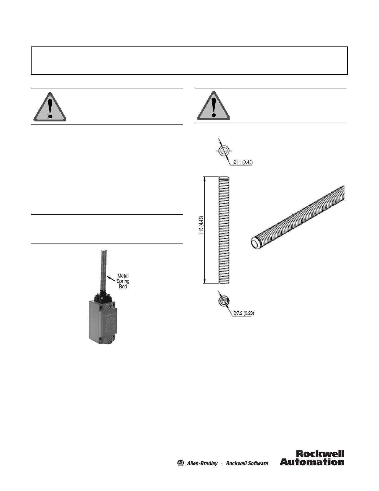
Metal spring rod shown installed.
Bulletin 440P-WM4 Metal Spring Rod
ATTENTION: To avoid electrical shock and unintended
operation of equipment, disconnect all
power to the limit switch and the controlled
equipment before proceeding with any
repair or adjustment of the limit switch.
General Data
• Designed for 440P-M metal spring rod limit switches
• Spring rod diameter 11 mm (0.43 in.)
• Spring rod length 113 mm (4.45 in.)
Principles, Standards, and Implementation
Operating specifications must be followed. Actuators should
be displaced beyond the point where direct opening action
occurs. If adjustable actuators become loose they may defeat
the direct opening action feature of the limit switch. These
devices are not to be used to directly control a motor.
IMPORTANT: Installation of Allen-Bradley limit switches should be in
accordance with local and/or national codes. Servicing
energized industrial control equipment can be hazarous if
not in accordance to recommended safety procedures.
ATTENTION: Operator heads with adjustable actuators
should NOT be used for safety
applications.
Approximate Dimensions [mm (in.)]
Instructions
1. Remove old spring rod by holding the rubber gasket at the
base of the spring rod and turning the spring rod counterclockwise.
2. Thread the replacement spring rod onto the threaded post
shaft extending vertically from the operator head.
3. While holding the rubber gasket at the base of the spring
rod torque the spring rod clockwise to 1…1.4 N•m
(8.85…12.39 lb•in).
Page 2
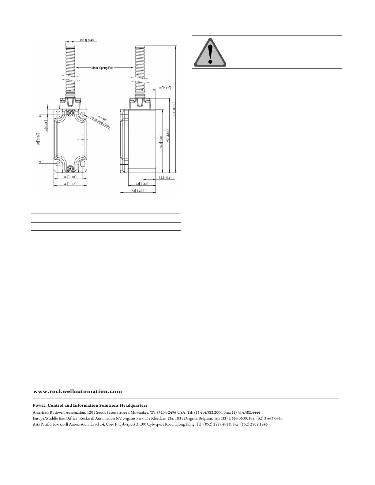
Mounting Dimensions [mm (in.)]
Torque Specifications
ATTENTION: Under no circumstances must the switch
be actuated beyond the mechanical travel
specified. Serious damage to the device
and property could result.
Maintenance
These devices require little maintenance, but routine visual
inspection is recommended to keep foreign debris from
collecting on the exterior actuators and rollers.
Removing the operator head is not recommended as loose
internal components may be lost or improperly re-installed.
Actuation Guidelines
The method of actuation and over travel has significant
influence on the service life of the limit switch. To maximize
the service life, it is recommended to provide an actuator with
a 30° pressure angle and a surface hardness of RC-45 max.
Location Torque
Metal spring rod 1…1.4 N•m (8.85…12.39 lb•in)
Drwg. No. 10000101188 Ver 00
February 2011
Printed in USA
 Loading...