

Page 1
Installation and Operating Instructions
IMPORTANT: SAVE THESE INSTRUCTIONS FOR FUTURE USE.
IMPORTANT
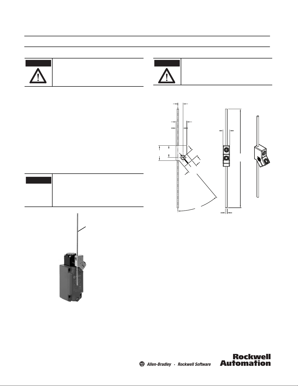
Adjustable metal rod lever
shown installed.
Metal rod lever
ATTENTION
19.3
8.5
0.335
17.6
0.693
11.5
0.453
24.3
0.957
0.760
12.73
0.502
16.18
0.637
40°
160.0
6.300
11.0
0.433
3.0 (0.118) dia.
Bulletin 440P-WM3 Metal Rod Lever
ATTENTION
To avoid electrical shock and unintended
operation of equipment, disconnect all power
to the limit switch and the controlled
equipment before proceeding with any repair
or adjustment of the limit switch.
General Data
• Designed for 440P-M metal rod lever limit switches
• Rod lever sweep range up to 40°
• Rod lever diameter 3 mm (0.12 in.)
• Rod lever length 160 mm (6.3 in.)
• Rod lever max extension 143 mm (5.63 in.)
• Includes collar and one Allen head screw
Principles, Standards, and Implementation
Operating specifications must be followed. Actuators should
be displaced beyond the point where direct opening action
occurs. If adjustable actuators become loose they may defeat
the direct opening action feature of the limit switch. These
devices are not to be used to directly control a motor.
Installation of Allen-Bradley limit switches
should be in accordance with local and/or
national codes. Servicing energized industrial
control equipment can be hazardous if not in
accordance to recommended safety
procedures.
Operator heads with adjustable actuators
should NOT be used for safety applications.
Approximate Dimensions [mm (in.)]
Instructions
1. Position the collar on the shaft to the desired position.
2. Tighten the collar shaft Allen head screw to 2.7…3.7 N•m
(23.9…32.75 in•lb).
3. Insert the metal rod lever into the collar shaft hole.
4. Adjust the position of the metal rod lever to the desired
length.
5. Tighten the adjustable rod lever Allen head screw to
1.5…2.1 N•m (13.28…18.59 in•lb).
Page 2
Power, Control and Information Solutions Headquarters
Americas: Rockwell Automation, 1201 South Second Street, Milwaukee, WI 53204-2496 USA, Tel: (1) 414.382.2000, Fax: (1) 414.382.4444
Europe/Middle East/Africa: Rockwell Automation NV, Pegasus Park, De Kleetlaan 12a, 1831 Diegem, Belgium, Tel: (32) 2 663 0600, Fax: (32) 2 663 0640
Asia Pacic: Rockwell Automation, Level 14, Core F, Cyberport 3, 100 Cyberport Road, Hong Kong, Tel: (852) 2887 4788, Fax: (852) 2508 1846
www.rockwel lautomation.com
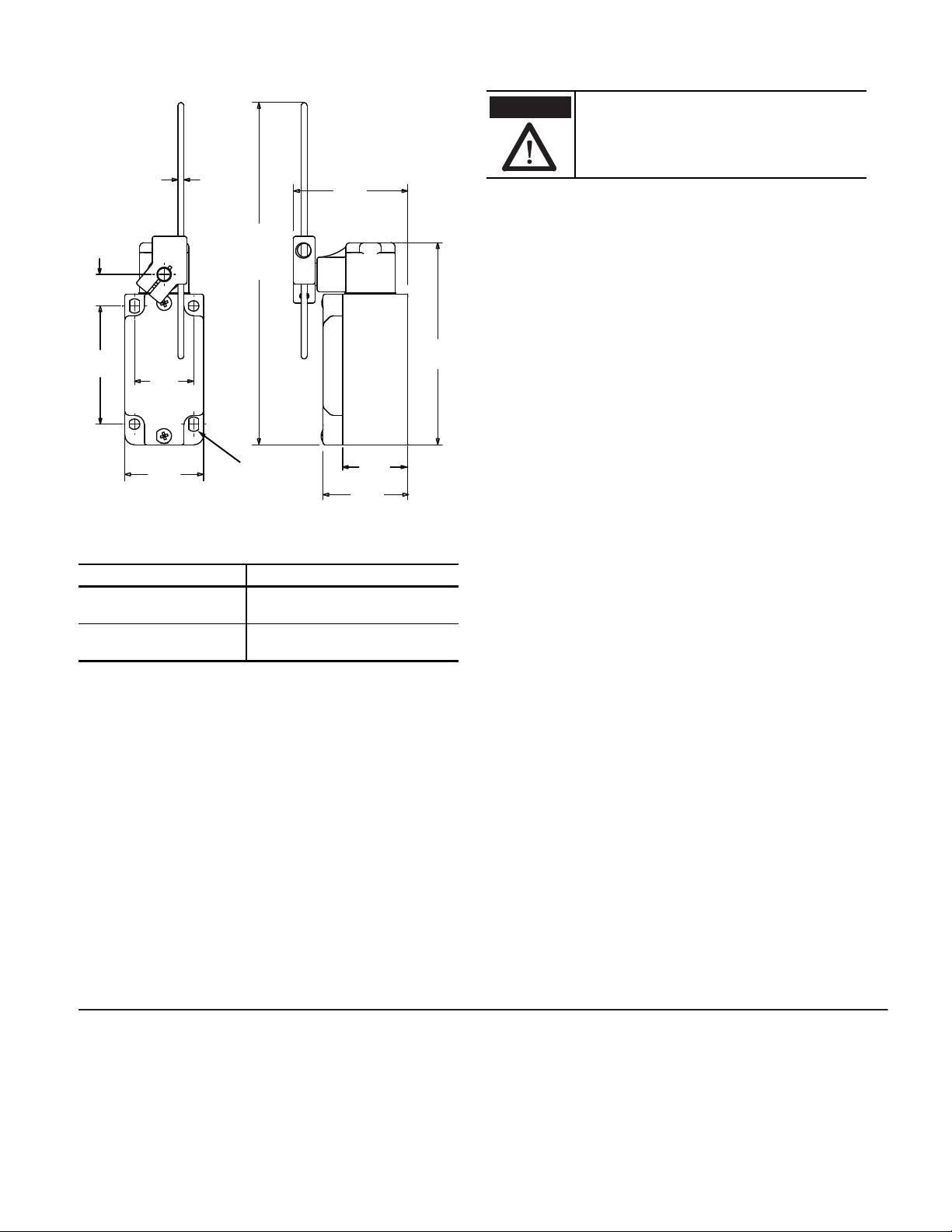
Mounting Dimensions [mm (in.)]
60
(2.36)
16
(0.62)
3
(0.12)
dia.
43
(1.69)
40
(1.57)
30
(1.18)
57
(2.24)
240
(9.44)
103
(4.05)
33
(1.29)
Max.
Extension
4 x M5
Mounting holes
ATTENTION
Under no circumstances must the switch be
actuated beyond the mechanical travel
specified. Serious damage to the device and
property could result.
Maintenance
These devices require little maintenance, but routine visual
inspection is recommended to keep foreign debris from
collecting on the exterior actuators and rollers.
Removing the operator head is not recommended as loose
internal components may be lost or improperly re-installed.
Actuation Guidelines
The method of actuation and over travel has significant
influence on the service life of the limit switch. To maximize
the service life, it is recommended to provide an actuator with
a 30° pressure angle and a surface hardness of RC-45 max.
Torque Specifications
Location Torque
Rod lever 3 mm Allen
head screw
Collar shaft 3 mm Allen
head screw
1.5…2.1 N•m (13.28…18.59 in•lb)
2.7…3.7 N•m (23.9…32.75 in•lb)
Copyright © 2012 Rockwell Automation, Inc. All Rights Reserved. 10000101187 Ver 01
June 2012
 Loading...