

Page 1
Installation and Operating Instructions
IMPORTANT: SAVE THESE INSTRUCTIONS FOR FUTURE USE.
This publication does not include all specifications, dimensions, or any special installation
considerations. Refer to the product catalog pages for additional information.
To avoid electrical shock and unintended operation of
equipment, disconnect all power to the limit switch and
the controlled equipment before proceeding with any
repair or adjustment of the limit switch.
Installation of Allen-Bradley Guardmaster products
should be in accordance with local and/or national
codes. Servicing energized industrial control equipment
can be hazardous if not in accordance with
recommended safety procedures.
Bulletin 440P Small Metal Safety Position Switches
ATTENTION
General Data
• Safety contacts: 1 N.C.
• Auxiliary contacts: 1 N.O.
• Enclosure rating:
• NEMA 1
• IP66, IP67, IP69K
• Rugged die cast housing
• 2 m prewired cable
• Compact profile for access limited installation
Principles, Standards, and Implementation
Before installation in a safety application, perform a risk
assessment to determine whether the specifications of this
device are suitable for foreseeable operational and
environmental characteristics of the machine which is to be
controlled. Only the normally closed set of contacts are
considered safety contacts. When deploying these limit
switches in a safety system application, all applicable
standards for application should be followed. Operating
specifications must be followed. The actuator must be placed
beyond the point where Direct Opening Action occurs.
Do not use these devices to directly control a motor.
Specifications
Safety Ratings
EN 954-1, ISO 13849-1,
Standards
Safety Classification
Certifications
Functional Safety Data
IEC/EN 60204-1, NFPA 79, EN 1088,
ISO 14119, IEC/EN 60947-5-1,
ANSI B11.19 AS 4024.1
Cat. 1 Device per EN 954-1 Dual channel
limit switch suitable for Cat. 3 or 4
systems
cULus Listed, TÜV and CE Marked for all
applicable directives
6
B10d: 2x10
operations
Outputs
Safety Contacts 1 N.C. snap acting
Auxiliary Contacts 1 N.O. snap acting
Thermal Current (/
)
lth
10 A
Rated Insulation Voltage (ui) 300 AC
Short Circuit Protection
10 A max. fast acting fuse IEC 269 type
gG or equivalent
Contact Ratings
Maximum AC Contact Rating Per Pole (50/60 hz) Same Polarity
NEMA Rating
Designation
Max.
Vol tag e
Amperes Continuous
Make Break Make Break
Carrying Current
(Amp.)
Vol tam per es
AC15/ B300 120 30 3 5 3600 360
AC15/ B300 240 15 1.5 5 3600 360
Maximum AC Contact Rating Per Pole (50/60 hz) Same Polarity
DC13/ Q300 240 0.27 0.27 2.5 69 69
Operating Characteristics
Actuation Speed, Max. 250 mm/s
Actuation Speed, Min. 100 mm/min
Actuation Frequency, Max. 6000 ops/hr
Mechanical Life
7
operations at room temperature
1 x 10
Environmental
Enclosure Type Rating NEMA 1, IP66/IP67/IP69K
Operating Temperature [C (F)] 2…70 ° (35.6…158 °)
Pollution Degree 3
Physical Characteristics
Housing Material Die cast alloy
Actuator Material Various polymers and metals
Mounting 2 x M4, any position
Vibration
IEC 68-2-6 (10…55 Hz, 0.35 mm
amplitude)
Shock IEC 68-2-7 (30 Gn 3 pulses per axis)
Connection 2 m (6.5 ft) cable
Enclosure Color Red body/black head
Page 2
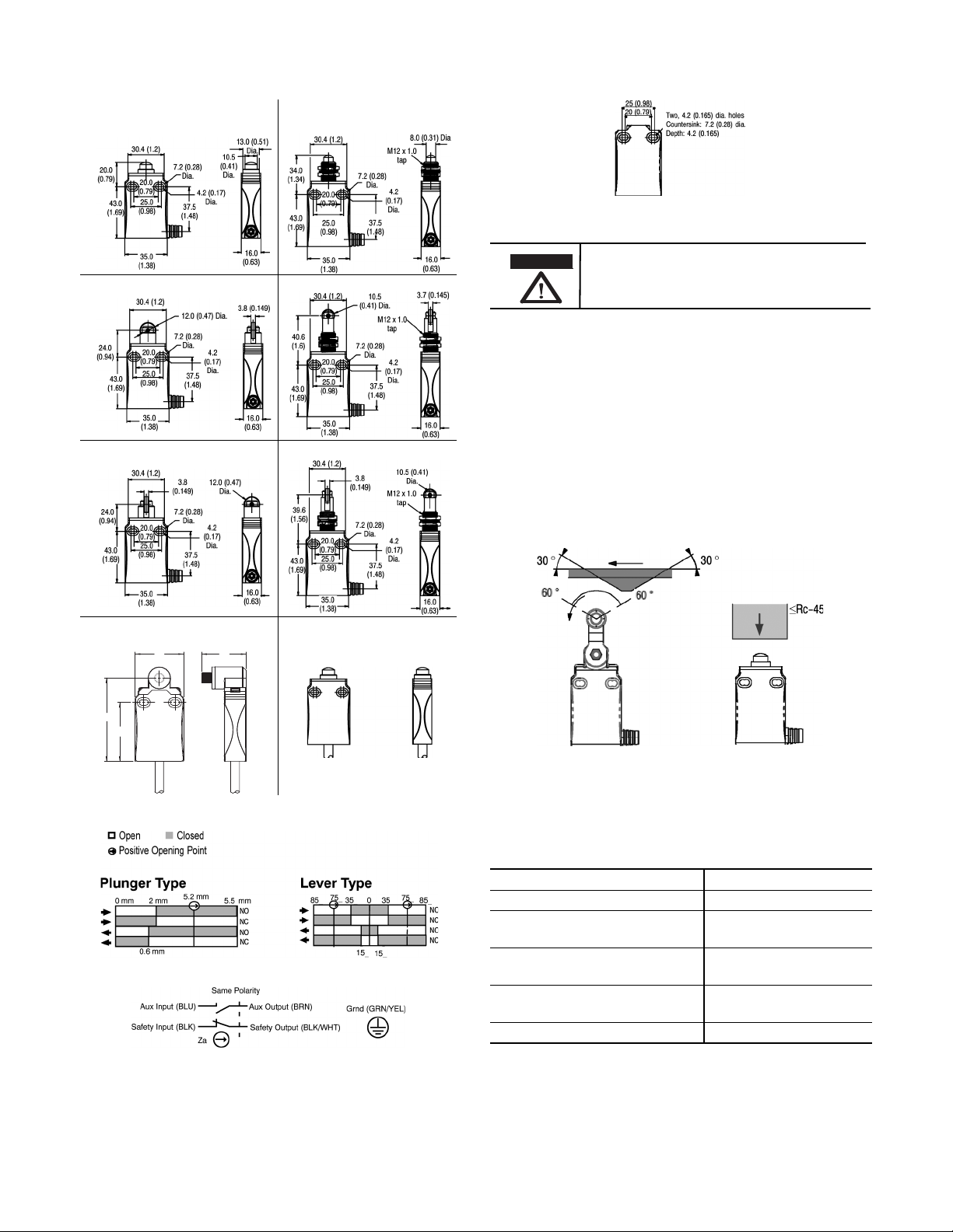
Nonpanel Mount Panel Mount
Dome
Plunger
Cross Roller Plunger
Bottom Cable Style
32.2
(1.27)
35.0
(1.37)
43.0
(1.69)
6.10
(2.40)
Replacement Switch, without
a Lever (440P-NX10)
Roller Plunger
Under no circumstances must the switch be actuated
beyond the mechanical travel specified. Serious
damage to the device and property could result.
Mounting Dimensions [mm]
Countersink Hole
\
• Panel mount clearance hole = 13 mm (0.51 in.) max.
ATTENTION
Maintenance
These devices require little maintenance, but routine visual
inspection is recommended to keep foreign debris from
collecting on the exterior actuators and rollers. Removing the
operator head is not recommended as loose internal
components may be lost or improperly re-installed.
Actuation Guidelines
The method of actuation and over travel has significant
influence on the service life of the limit switch. To maximize
the service life, it is recommended to provide an actuator with
a 30° pressure angle and a surface hardness of Rc-45 max.
Contact Opening Characteristics
Wiring Diagram
Lever Positioning
Some rotary switches are supplied with levers that are
mechanically coupled to the actuating shaft. The lever may be
removed and re-installed to adjust cam tracking. See table
below for torque recommendations.
Torque Specifications
Location Torque
3.5 mm Operator Head Phillips Screws 0.8 N•m (7.1 lb•in)
Short and Wide Roller Lever A rm
8 mm Hex Nut
Adjustable Lever Arm
4 mm Allen Head Screw
Adjustable Lever Arm Collar
3 mm Allen Head Screw
1.0 N•m (8.85 lb•in)
1.8…2.8 N•m
(15.93…24.78 lb•in)
3.2 N•m (28.32 lb•in)
12 mm Panel Mount Nut 1.5 N•m (13.28 lb•in)
2
Page 3

Mounting Dimensions [mm (in.)]
Note: Lever arm versions are nonpanel mount only.
Operator heads with adjustable actuators should NOT
be used for safety applications.
Ø4.2
(0.17)
5.2
(0.2)
Short Lever Arm
8 mm Hex Nut
25
(0.98)
18
(0.71)
43
(1.69)
30.4 (1.2)
20
(0.79)
25
(0.98)
35 (1.38)
Ø13.5
(0.53)
Ø7.2
(0.28)
18
(0.71)
43
(1.69)
35.8 (1.41)
16 (0.63)
Ø13.5
(0.53)
(0.98)
(0.71)
(1.69)
Ø16.5 (0.65)x7
R27 (Min)
R105 (Max)
Adj. Lever Arm 4 mm
Allen Head Screw
Two 4.2 (0.17) Dia. Holes
Countersink: 7.2 (0.28) Dia.
Depth: 4.2 (0.17)
Adj. Lever Arm Collar
3 mm Allen Head Screw
20 (0.79)
25 (0.98)
30.4 (1.2)
Ø13.5
(0.53)
25
18
20
(0.79)
43
25
(0.98)
35 (1.38)
43.4 (1.71)
38.2 (1.5)
Ø7.2
(0.28)
Ø4.2
(0.17)
3.5 mm Operator Head
25
(0.98)
Wide Roller Lever Arm
Philips Screw
25.4 (1)
8 mm Hex Nut
35.15 (1.38)
16 (0.63)
35 (1.38)
16 (0.63)
3
Page 4

Drwg. No. 10000020920 Ver 05
440P-IN002C-EN-P
May 2013 — Printed in USA
 Loading...