

Page 1
Installation Instructions
PHOTOSWITCH Bulletin 42FT SelfĆTeach Fiber Optic
IMPORTANT: SAVE THESE INSTRUCTIONS FOR FUTURE USE.
Description
The 42FT is a compact, DIN Rail Mount Fiber Optic
Photoelectric sensor with sophisticated part detection,
diagnostic, and self-teach capabilities.
Five LED indicators provide diagnostic and alignment
information. A dynamic diagnostic output signals when margin
levels are below a predetermined threshold for seven
successive detections.
The self-teach capability allows the Bulletin 42FT to determine
an optimum sensitivity and hysteresis setting for a specific
application. The remote lockout feature can be used to help
prevent unauthorized changes to these adjustments. A switch
selectable 50ms off-delay (“pulse stretcher”) is useful in high
speed applications where the output pulse must be lengthened
to allow time for the machine logic to respond.
42FT sensors are designed for DIN rail mounting. For
installation convenience, a steel mounting bracket is supplied
for separate mounting.
42FT sensors are designed for use with 2.2mm diameter
plastic fiber optic cables. An adaptor is supplied with the
sensor to use 1.25mm diameter plastic fiber optic cables. Fiber
optic cables are held in place by a rotating collar. No tools are
required to attach or remove fiber optic cables. Special glass
fiber optic cables are also available. Over 40 compatible
standard plastic and glass fiber optic cables are available,
please refer to page 1–232 of the C112 Sensor catalog.
Features
S Pico quick-disconnect available
S (5) LED indicators: 0.8X to 1.6X margin and output
S Manual or Self-Teach sensitivity adjustment
S Manual or Self-Teach hysteresis adjustment
S Stability output
S Visible red, green, or blue light sources
S Selectable light or dark operate
Features (continued)
S Selectable 50ms off-delay output (pulse stretcher)
S Can be DIN rail mounted or separately mounted
S No tools required to attach or remove Fiber Optic cables
General Specifications
Output Protection Short circuit, Reverse polarity, False pulse, Transient noise
Housing Materials ABS resin, polycarbonate cover
Cable Construction 2m (6.5ft) 500V PVC jacketed 24AWG multiĆconductor
Supplied
Accessories
Operating
Environment
Vibration 10-55Hz, 1mm amplitude, Meets or exceeds IEC 947-5-2
Ambient
Temperature
Relative
Humidity
Approvals UL listed and CSA certified, and CE marked for applicable
Emitter LED Visible red 660nm: 42FT-F2LNA-XX
Connections Cable:
cable
Adjustment screwdriver, 1.25mm diameter fiber optic cable
adaptors
NEMA 1, 4X, 12, 13 and IP66 (IEC 529) (Mounting bracket
not NEMA 4X)
Shock 30G, Meets or exceeds IEC 947-5-2
-25°C to +55°C (-13°F to +131°F)
85%
directives
Visible green 565nm: 42FT-F3LNA-XX
Visible blue 450nm: 42FT-F6LNA-XX
5Ćconductor PVC 3Ćpin pico quickĆ
jacketed cable 2m (6.5ft) disconnect style
42FT-F2LNA-A2 42FT-F2LNA-Y3
42FT-F2LPA-A2 42FT-F2LPA-Y3
42FT-F3LNA-A2 42FT-F3LNA-Y3
42FT-F3LPA-A2 42FT-F3LPA-Y3
42FT-F6LNA-A2 42FT-F6LNA-Y3
42FT-F6LPA-A2 42FT-F6LPA-Y3
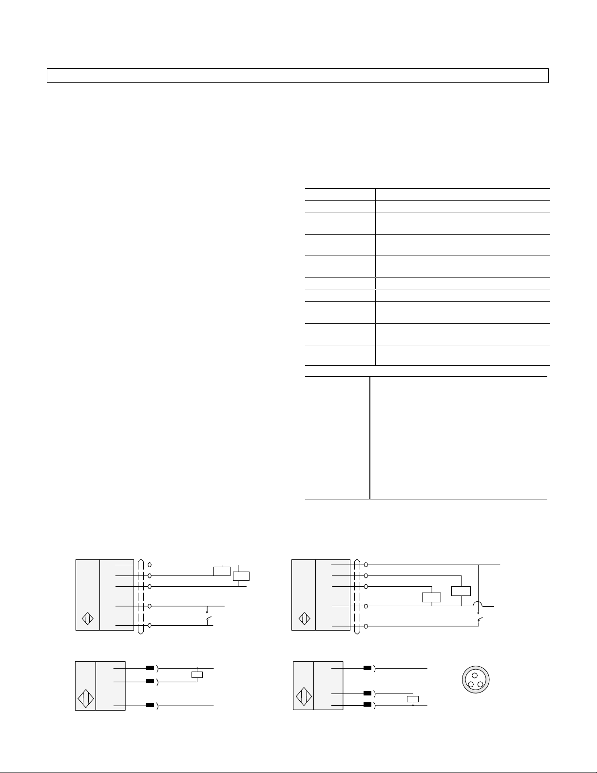
Wiring
NPN Output
Cable
Cable
Brown: 12V-24V DC
Black: Output
Orange: Stability Output
Blue: -DC
Pink: External Set
Load
Load
Remote Self
Teach Activate
QuickĆDisconnect
1
4
3
Note: Details regarding connection of Allen-Bradley Bulletin 42FT photoelectric sensors to Allen-Bradley Program m able Controllers
can be found in publication 42-2.0.
Brown
Black
Blue
PNP Output
Cable
1
4
3
Brown: 12V-24V DC
Black: Output
Orange: Stability Output
Blue: -DC
Pink: External Set
Brown
Black
Blue
Load
Load
Pic
o
4
13
Remote Self
Teach Activate
1
Page 2
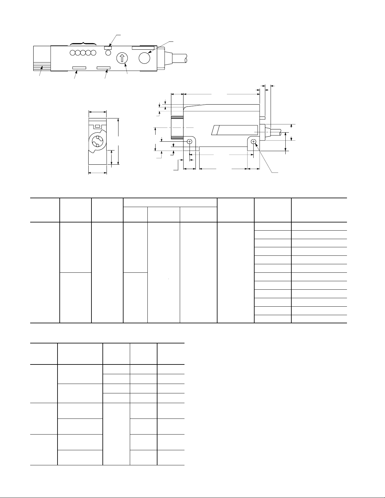
Dimensions—mm (inches)
12-24V DC
Light/Dark
100mA
y
Diffuse
Transmitted Beam
Light Level
(Margin) Indicator
Light
-
1
1
Set Indicator (Flashes During
Automatic Sensitivity Setting)
Set Self Teach+3+2+
Self Teach Button
(Steps Sensitivity or Hysteresis Up or
Down Depending on Mode Switch
Selection)
Cable Clamp
Normal/Off
Delay Switch
Light Operate/Dark
Operate Switch
13
(0.511
)
13.5
(0.413)
(0.531)
Mode Switch (Run, Set,
Auto, Hysteresis, Sensitivity)
34
(1.338)
10.5
Visible Red, Green, or Blue Fiber Optic
Operating
Voltage
12-24V DC Light/Dark
±10%
Supply
Current
Output
Energized
60mA PNP
Selectable
50mA NPN
Type
9
(0.354)
2
(0.078)
3
(0.118)
17
(0.669)
3
6.7
(0.118)
(0.263)
4.5
(0.177)
9
(0.354)
Output Characteristics
Max Load
Current
Output:
100mA
Stability:
50mA
Max Leakage
Current
56
(2.204)
47
(1.850)
35.3
(1.389)
Response
Time
0.5mA 500µs
4
(0.157)
(0.354)
9
4
(0.157)
12
(0.472)
13.5
(0.531)
Dia. 3.2 x 3.6
(0.126 x 0.142) 2 Places
Emitter LED Catalog Number
Red 42FT-F2LPA-A2
Red 42FT-F2LPA-Y3
Green 42FT-F3LPA-A2
Green 42FT-F3LPA-Y3
Blue 42FT-F6LPA-A2
Blue 42FT-F6LPA-Y3
Red 42FT-F2LNA-A2
Red 42FT-F2LNA-Y3
Green 42FT-F3LNA-A2
Green 42FT-F3LNA-Y3
Blue 42FT-F6LNA-A2
Blue 42FT-F6LNA-Y3
Typical Glass Fiber Optic Cable Selection—mm (in)
2
LED Sensing Mode
Diffuse
(Bifurcated Fiber)
Red
Transmitted Beam
(Individual Fiber)
Diffuse
(Bifurcated Fiber)
Green
Transmitted Beam
(Individual Fiber)
Diffuse
(Bifurcated Fiber)
Blue
Transmitted Beam
(Individual Fiber)
Plastic
Fiber
Diameter
Typical
Fiber
Model
MaxiĆ
mum
Range
1 (0.040) 99-94 110 (4.3)
0.5 (0.020) 99-808 30 (1.2)
1 (0.040) 99-90 350 (13.2)
0.5 (0.020) 99-822 95 (3.7)
99-94 13 (0.5)
99-90 35 (1.4)
1 (0.040)
99-94 18 (0.7)
99-90 60 (24)
Mode Switch
AUTO (Factory Setting)
Allows Self-Teach to be initiated with the pushbutton on the
sensor (Local) or through an external connection (Remote).
Sensor indicators and outputs are active and function normally.
Sensors may be operated in AUTO mode. Sensors must be
operated in AUTO mode when Remote Self-Teach is required.
SET
Allows self-teach to be initiated with the pushbutton on the
sensor (Local) only. The external Self-Teach connection
(Remote) is ignored. Sensor indicators function normally. Both
sensor and stability outputs are inhibited.
RUN
RUN mode is recommended for sensor operation in all
applications where Remote Self-Teach will not be used.
Sensor indicators and outputs are active and function normally.
No adjustments, Local or Remote, are possible while the
sensor is in RUN mode.
Page 3

Two RUN switch positions are provided. For applications in
close proximity, alternate sensors should be set to alternate
RUN positions to reduce the possibility of crosstalk.
SENS
Allows Sensitivity to be increased (+) or decreased (–)
manually. See Manual Adjustment section for information.
Self-Teach
Self-Teach can be initiated using the pushbutton on the sensor
(Local) or through an external input (Remote) in the AUTO
mode. Only Local Self-Teach is possible in the SET mode.
Refer to the Mode Switch section for a description of each
Mode Switch setting.
HYS
Allows Hysteresis to be increased (+) or decreased (–)
manually. See Manual Adjustment section for information.
D.O./L.O. Switch
Selects Dark Operate or Light Operate sensor output.
OFF DLY/NORMAL Switch
OFF DLY position enables a 50ms off-delay on the sensor
output (“pulse-stretcher”). NORMAL disables the off-delay.
Indicators
As more light is detected, more indicators will illuminate.
Green “–1” 0.8X margin
Red “LIGHT” 1.0X margin
The Sensor Output changes state whenever
this indicator turns ON or OFF
Green “+1” 1.2X margin
Green “+2” 1.4X margin
Green “+3” 1.6X margin
Green “SET” Verifies adjustment inputs.
Alignment
All Sensing Modes—Mount the sensor securely. Attach the
fiber optic cable(s) to the sensor and fasten the sensing end
tip(s) loosely at the point where the target object is to be
sensed. Apply power to the sensor. Set the mode switch to
SET.
Diffuse Sensing—Place the target object in the position
where it is to be sensed. Watch the margin indicators and pan
the light source fiber optic cable up and down, left and right to
center it on the target. Secure the sensing end tip at the point
yielding the greatest margin.
Transmitted Beam Sensing—Secure the “receiver” firmly in
position. Watch the margin indicators and pan the “light
source” fiber optic cable up and down, left and right to center it
on the “receiver” fiber optic cable. Secure the “light source”
sensing end tip at the point yielding the greatest margin.
Retroreflective Sensing—Watch the margin indicators and
pan the fiber optic cable end tip up and down, left and right to
center it on the reflector. Mount the sensing end tip at the point
yielding the greatest margin.
Alignment Aid
A special alignment assistance feature visibly increases the
brightness of the sensor light source, as seen at the tip of the
fiber optic cable, whenever the amount of light received by the
sensor is sufficient for stable operation.
Reducing the Potential for Crosstalk
Crosstalk can occur when the fiber optic cables of two sensors
are positioned to sense at points close to each other. Adjust
each sensor independently while the other sensor is not
powered. Once adjusted set each sensor to a different RUN
position on the Mode Switch. (Note that two positions on the
Mode Switch are labeled RUN.)
Local Self-Teach
Moving Target Objects
1. Set Mode Switch to AUTO or SET.
2. Press and hold the SET button. The SET indicator flashes
rapidly for three seconds while the sensor prepares to
monitor the passing target objects then flashes more
slowly as the sensor actually monitors the light received
as the target objects pass. The sensor monitors the light
received as long as the button remains pressed.
3. Allow at least one target object to pass completely while
the SET indicator flashes slowly before releasing the
button. Automatic Sensitivity adjustment is complete.
(Note: Self-Teach will not occur if the button is released
early.)
4. Set Mode Switch to AUTO or one of the RUN positions
(see the description of operation in the Mode Switch
section.)
Stationary Target Objects
1. Set Mode Switch to AUTO or SET.
2. Remove the target object and press and release the SET
button. The SET indicator flashes continuously to confirm
that the “no target” signal is stored.
3. With the target object in its sensing position press and
release the SET button. The SET indicator stops flashing
to confirm that Local Self-Teach is complete.
4. Set Mode Switch to AUTO or one of the RUN positions
(see the description of operation in the Mode Switch
section).
Remote Self-Teach
1. Set Mode Switch to AUTO. An external signal or switch
closure can be used to automatically adjust sensitivity and
hysteresis via the pink External Set wire (refer to wiring
diagrams).
2. The adjustment procedure is the same as described in the
Manual Self-Teach section except that the external signal
or switch closure takes the place of manually pressing
SET button. The duration of External Set signal or switch
closure must be at least 100ms. The Stability Output
pulses to provide a verification signal which duplicates the
blinking of the SET indicator as described above.
3. Set Mode Switch to AUTO or one of the RUN positions
(see the description of operation in the Mode Switch
section.)
Manual Adjustment
Setting Maximum Sensitivity
1. Set Mode Switch to AUTO or SET.
2. Diffuse Sensing
Remove the target object and press and release the SET
button twice.
Transmitted Beam or Retroreflective Sensing
Completely block the beam from source to receiver or
3
Page 4

from fiber optic cable to reflector. Press and release the
SET button twice.
The SET indicator blinks OFF, briefly, after each press of
the SET button to confirm the Sensor has been set to
maximum sensitivity.
3. Set Mode Switch to AUTO or one of the RUN positions
(see the description of operation in the Mode Switch
section).
Adjusting Sensitivity
Increase—Set the Mode Switch to SENS +.
Decrease—Set the Mode Switch to SENS –.
1. Press and release the SET button. Sensitivity is increased
(or decreased) each time the SET button is pressed and
released. Press and release the SET button until the
desired sensitivity is reached. The SET indicator turns off
once, briefly, each time until the limit of the adjustment
range is reached. The SET indicator no longer blinks
when the upper or lower limit has been reached.
2. Set Mode Switch to AUTO or one of the RUN positions
(see the description of operation in the Mode Switch
section).
Adjusting Hysteresis
Increase—Set the Mode Switch to HYS +.
Decrease—Set the Mode Switch to HYS –.
1. Press and release the SET button. Hysteresis is increased
(or decreased) each time the SET button is pressed and
released. Press and release the SET button until the
desired hysteresis is reached. The emitted light at the fiber
tip and the SET indicator turn off once, briefly, each time
until the limit of the adjustment range is reached. The
emitted light at the fiber tip and the SET indicator no
longer blink when the upper or lower limit has been
reached.
2. Set Mode Switch to AUTO or one of the RUN positions
(see the description of operation in the Mode Switch
section).
Self Diagnostic/Stability Output
Self Diagnostic Upon Power Up
The sensor has a built-in self diagnostic program. Upon power
up, this program verifies that sufficient input light is being
detected.
Upon power up the light received by the sensor is measured
for 3 seconds. If the light is below +1 (1.2X margin), the
stability output signal is turned on.
Application Quality Verification
In diffuse applications, it is desirable to have a margin of less
than 0.8X when the target is absent and a margin of greater
than 1.2X when the target is present.
In transmitted beam and retroreflective applications, it is
desirable to have a margin of greater than 1.2X when the
target is absent and a margin of less than 0.8X when a target
is present.
The diagnostic output of the 42FT will turn on when application
margin levels are not less than 0.8X or greater than 1.2X for
seven successive detections.
If seven consecutive input signals are below the +1 level (1.2X
margin), the stability output signal turns on to indicate that the
application is not stable (see Ê).
If seven consecutive input signals are above the –1 level (0.8X
margin), the stability output signal turns on to indicate that the
application is not stable (see Ë).
Stability Output
Input Signal
Level
Level +1
1.2:1
On
1:1
Off
0.8:1
Level -1
Stability Output
Ê 7 Low Margin Detections
Trip Stability Output
Ë 7 High Margin Detections
Trip Stability Output
OffOff
Instability
Range
OnOn
Publication 75009–056–01(E)
May 1999
Printed in Japan
4
 Loading...