

Page 1

Installation Instructions
MobileView Connection Cable
(Catalog Number 2727-MRT5, -MRT10, -MRT15, -MRT20)
Inside . . .
English ................................................................................................................................ 3
Français .............................................................................................................................. 9
Deutsch ............................................................................................................................ 15
Español ............................................................................................................................. 21
Italiano ............................................................................................................................. 25
Português ..........................................................................................................................33
Publication 2727-IN004C-MU-P
Page 2

Page 3

Installation Instructions
MobileView Connection Cable
(Catalog Number 2727-MRT5, -MRT10, -MRT15, -MRT20)
English
The MobileView Connection Cable connects the following machine terminals to the
MobileView Junction Box (2727-MRJB1) via the MobileView Junction Box Cable
(2727-MREX1)
• MobileView Guard G750
• MobileView Machine Terminal MT750
The MobileView Connection Cable is available in the following lengths:
• 5 meter/16.4 foot (2727-MRT5)
• 10 meter/32.8 foot (2727-MRT10)
• 15 meter/49.2 foot (2727-MRT15)
• 20 meter/65.6 foot (2727-MRT20)
Inside. . .
MobileView Connection Cable .......................................................................................... 4
Connection Cable Diagram ................................................................................................ 4
Attaching the Connection Cable to the MobileView Terminal .......................................... 5
Connection Cable Compartment ........................................................................................ 6
Attaching Connection Cable for Left or Right-Hand Operation ......................................... 7
Connecting the MobileView Terminal to the Junction Box ............................................... 8
Publication 2727-IN004C-MU-P
Page 4
4 MobileView Connection Cable
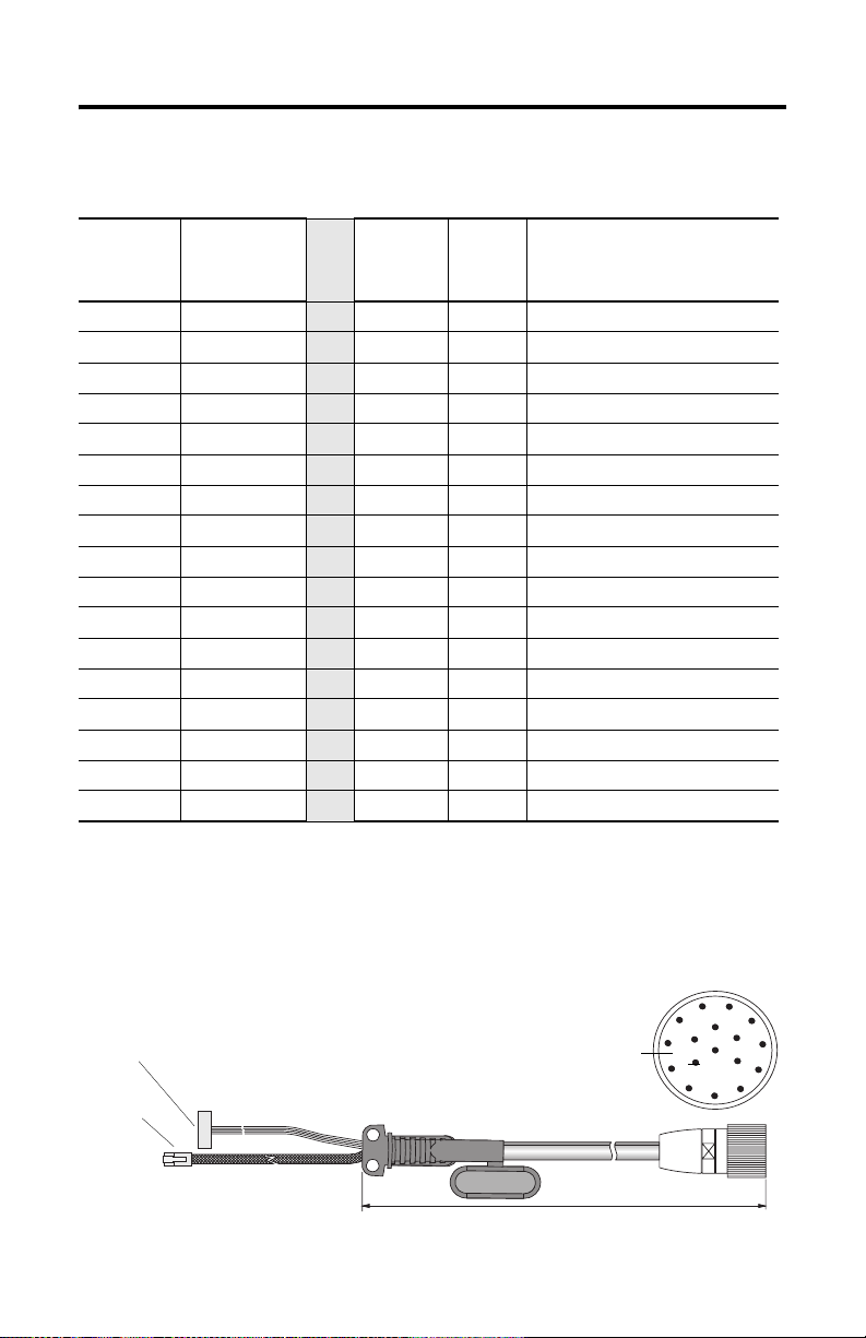
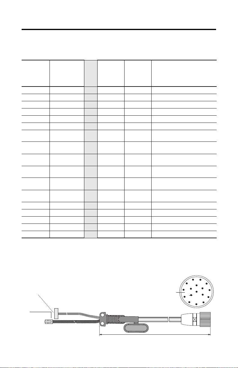
MobileView Connection Cable
K1, 17-pin
Circular
Jack Pin #
MobileView
Connection
Cable
Wire Color
K3, 11-pin
female
connector
S19
K2, 8-pin
RJ-45
Ethernet
Description
1 pink -->> 6 - 24V dc
2 black -->> 7 - GND_IN
3 green-brown -->> 8 - E-stop, circuit 1, positive *
4 white-green -->> 9 - E-stop, circuit 1, negative *
5 grey-pink -->> 10 - E-stop, circuit 2, positive *
6 red-blue -->> 11 - E-stop, circuit 2, negative *
7 brown -->> 1 - Enabling switch, circuit 1, positive *
8 yellow -->> 2 - Enabling switch, circuit 1, negative *
12 green -->> 3 - Enabling switch, circuit 2, positive *
17 grey -->> 4 - Enabling switch, circuit 2, negative *
9 bridge to pin 10 -->> - - Not used
10 bridge to pin 9 -->> - - Not used
11 violet -->> 5 - Not used
13 blue -->> - 1 TD+ (transmit)
14 white -->> - 2 TD- (transmit)
15 orange -->> - 3 RD+ (receive)
16 red -->> - 6 RD- (receive)
* For connection to MobileView Guard G750 terminals only.
Connection Cable Diagram
K3, 11-pin female connector to S19
at MobileView terminal.
K2, 8-pin
RJ-45 jack
to S4 at
MobileView
terminal.
Publication 2727-IN004C-MU-P
K1, 17-pin
circular connector
5, 10, 15 or 20 mm
(6.4, 32.8, 48.2 or 65.6 ft)
11
1
10
9
8
2
12
16
13
17
3
14
15
4
5
7
6
Page 5
MobileView Connection Cable 5
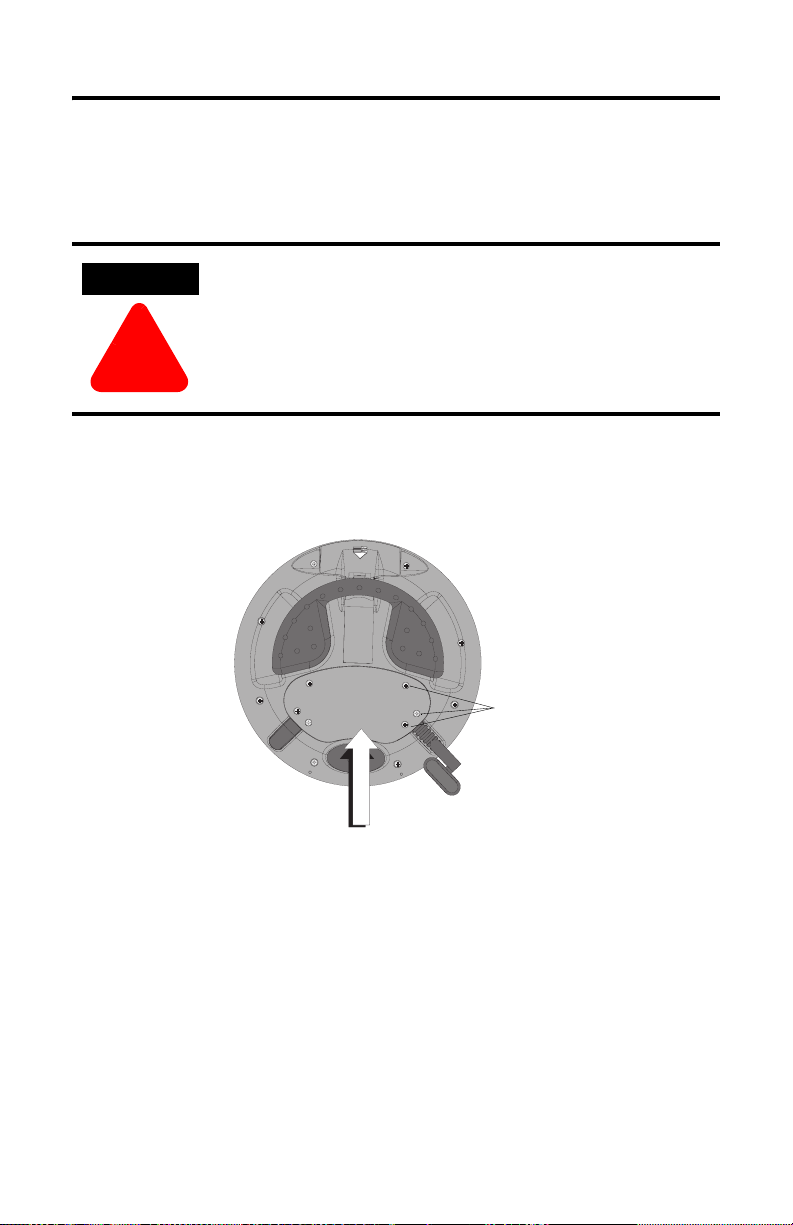
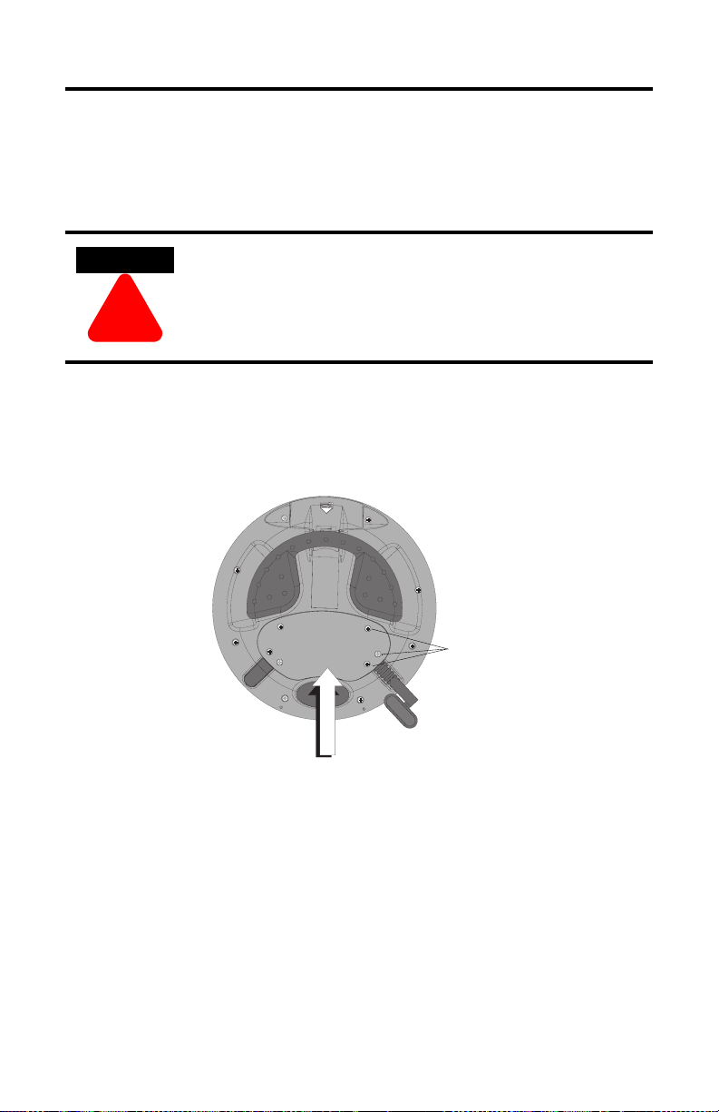
Attaching the Connection Cable to the MobileView Terminal
Removing the Back Cover
ATTENTION
Turn off the power supply before removing the back cover of
the MobileView terminal.
When the back cover is removed, the MobileView terminal is
sensitive to electrostatic discharge (ESD).
!
1. Place the terminal on a stable, flat surface.
2. Remove the 6 screws that secure the back cover to the MobileView terminal.
3. Carefully lift off the back cover and place it on a secure surface.
Screws
Back Cover
Publication 2727-IN004C-MU-P
Page 6
6 MobileView Connection Cable
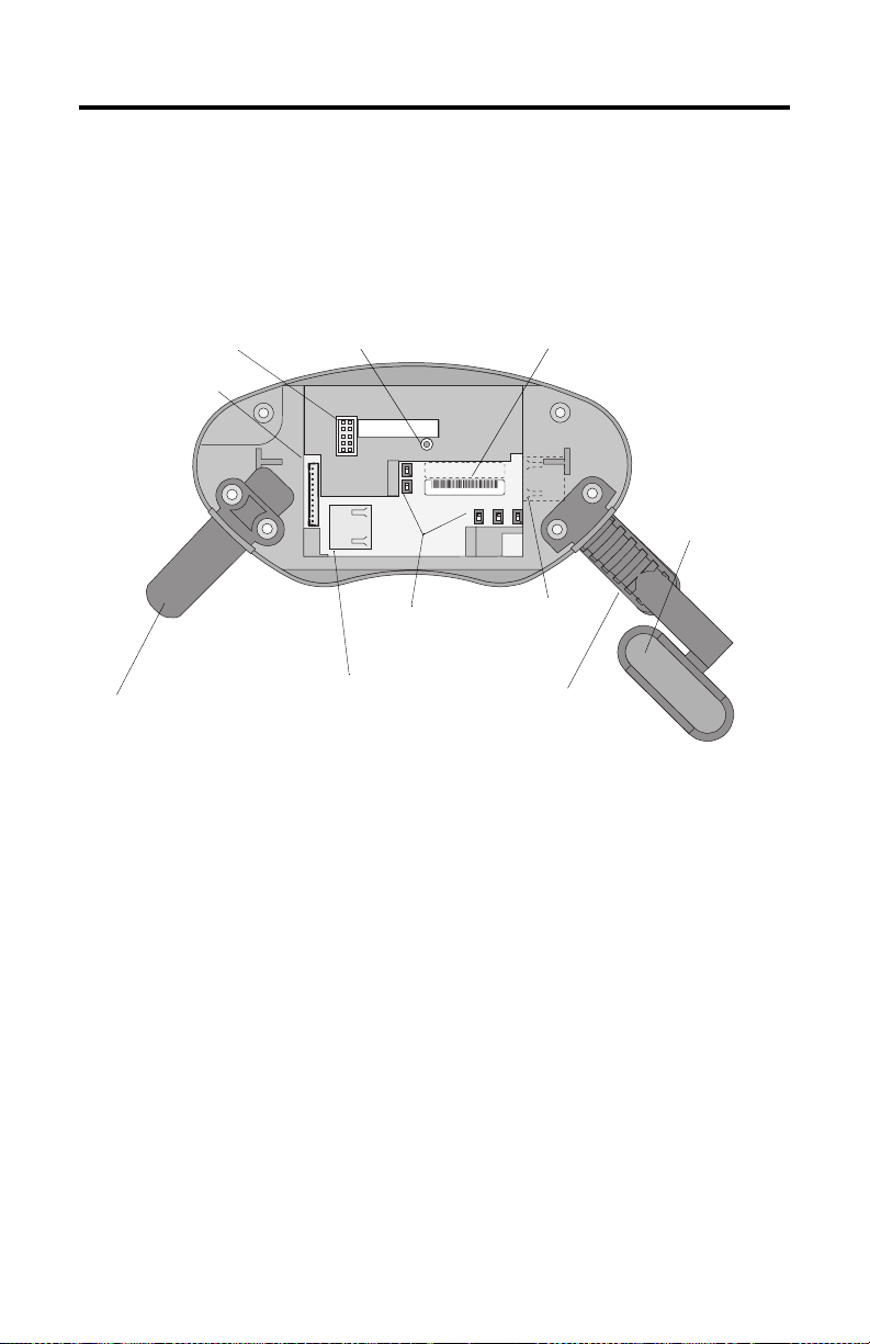
Connection Cable Compartment
The following illustration shows what the connection area of the MobileView
terminal looks like with the back cover removed.
Reset Button
RS-232 Port
for downloading software
Main Connector (S19)
for power supply and
control lines
for rebooting Windows CE
All data not flushed to Registry or
saved to Flash Storage is lost.
Pin 1
Serial
port
S19
Reset
B5
B4
00:60:B5:06:00:01
AABBCCDDEEFF
Ethernet
S4
Ethernet Label
Ethernet (Mac) Address
2250-00001
S6,
COM -Modul
B2 B6 B3
Cable Tag
uniquely identifies
terminal
Important: Install plug
on unused Connection Cable outlet.
Position of switches does
not affect terminal
operation (for future use)
Ethernet Connector (S4)
for data exchange
Connector
not used
Strain Relief
for connecting Connection
Cable on left or right
Publication 2727-IN004C-MU-P
Page 7
MobileView Connection Cable 7
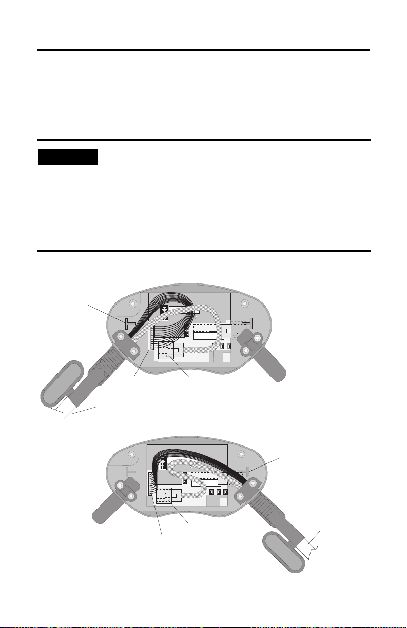
Attaching Connection Cable for Left or Right-Hand Operation
You can attach the MobileView Connection Cable on the left or right side of the
terminal for either left or right-hand operation. To relocate the cable, simply grasp
the strain relief and/or the plug and slide off of mount with a rocking motion.
IMPORTANT
Avoid routing cable
over T-support.
Make sure the K3, 11-pin female connector clicks completely into
the S19, Main Connector when plugged in. Ensure proper seating
of the K2, 8-pin RJ-45 jack into the S4, Ethernet Connector.
To avoid pinching the cable with the back cover, avoid laying
cable on top of the T-supports.
After routing the cable, secure the back cover to the terminal
with the 6 screws. Tighten screws to a torque of 4.42 in-lbs to
maintain IP54 degree protection.
Attaching Cable on Right
S6,
COM -Modul
Main Connector (S19)
Connection Cable
Attaching Cable on Left
S4, Ethernet Connector
Avoid routing cable
over T-support.
Main Connector (S19)
S6,
COM-Modul
S4, Ethernet Connector
Connection Cable
Publication 2727-IN004C-MU-P
Page 8
8 MobileView Connection Cable
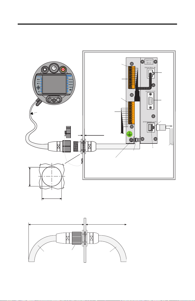
Connecting the MobileView Terminal to the Junction Box
MobileView Terminal
ESC
7 8 9
5 6
4
3
1 2
.
-
0
MobileView
Connection
Cable
Opening for Jack
0.94 in
24 mm
0.98 in ± 0.0039
25 mm ± 0.1
Run
KETOP
Dust Cover
Typical Control Cabinet
Pin 1, 24V dc
r
o
r
Er
MobileView Terminal
Connections
X1/K3
Pin 1, 24V dc
X2/K4
Safety Equipment
Connections (For
MobileView G750 only)
Junction Box
24V DC
+24V
TERM INAL IN
GND
ES1+
ES1-
ES2+
ES2-
ED1+
ED1-
ED2+
ED2-
RS 422 OUT
+24V
GND
ES1+
ES1-
ES2+
ES2-
ED1+
ED1-
ED2+
ED2-
ETHERNET OUT
ON LY
S1
S2
S3
maximum wall
thickness 5mm (0.2 in)
K1
Junction Box Cable
2 m (6.5 ft)
Use Grounding Screw
to connect Earth
Ground to the Junction
Box.
Junction Box
Cable Wire Tie
10 Base-T
Connection to
Ethernet Network
Cable Clearance on Both Sides of Enclosure Wall
130 mm (5.12 in)
Connection
Cable
Publication 2727-IN004C-MU-P
K1
Connection
100 mm (3.94 in)
Junction Box
Cable
Page 9

Notice d’installation
Câble de raccordement MobileView
(Références 2727-MRT5, -MRT10, -MRT15, -MRT20)
Français
Le câble de raccordement MobileView permet de connecter les terminaux suivants
au boîtier de raccordement MobileView (2727-MRJB1), par le biais du câble de
connexion du boîtier de raccordement MobileView (2727-MREX1) :
• MobileView Guard G750 ;
• MobileView Machine Terminal MT750.
Le câble de raccordement MobileView est disponible dans les longueurs suivantes :
• 5 mètres (2727-MRT5) ;
• 10 mètres (2727-MRT10) ;
• 15 mètres (2727-MRT15) ;
• 20 mètres (2727-MRT20).
Sommaire. . .
Câble de raccordement MobileView ............................................................................... 10
Schéma du câble de raccordement ................................................................................. 10
Fixation du câble de raccordement au terminal MobileView ......................................... 11
Compartiment du câble de raccordement ....................................................................... 12
Fixation du câble de raccordement côté droit ou côté gauche ....................................... 13
Connexion du terminal MobileView au boîtier de raccordement ................................... 14
Publication 2727-IN004C-MU-P - Month Year
Page 10
10 Câble de raccordement MobileView
Câble de raccordement MobileView
K1 :
connecteur
circulaire à
17 broches
Broche n°
Couleur des
fils du câble de
raccordement
MobileView
K3 :
connecteur
femelle à
11 broches
S19
K2 :
connecteur
RJ-45
Ethernet à
8 broches
Description
1 rose -->> 6 - 24 V c.c.
2 noir -->> 7 - Mise à la terre
3 vert-brun -->> 8 - Arrêt d’urgence, circuit 1, positif *
4 blanc-vert -->> 9 - Arrêt d’urgence, circuit 1, négatif *
5 gris-rose -->> 10 - Arrêt d’urgence, circuit 2, positif *
6 rouge-bleu -->> 11 - Arrêt d’urgence, circuit 2, négatif *
7 brun -->> 1 - Interrupteur d’activation, circuit 1,
8 jaune -->> 2 - Interrupteur d’activation, circuit 1,
12 vert -->> 3 - Interrupteur d’activation, circuit 2,
positif *
négatif *
positif *
17 gris -->> 4 - Interrupteur d’activation, circuit 2,
négatif *
9 pont vers
10 pont vers
broche 10
broche 9
-->> - - Non utilisée
-->> - - Non utilisée
11 violet -->> 5 - Non utilisée
13 bleu -->> - 1 TD+ (transmission)
14 blanc -->> - 2 TD- (transmission)
15 orange -->> - 3 RD+ (réception)
16 rouge -->> - 6 RD- (réception)
* Pour un raccordement aux terminaux MobileView Guard G750 uniquement.
Schéma du câble de raccordement
K3 : connecteur femelle à 11 broches pour connecteur S19
du terminal MobileView
K2 :
connecteur RJ-45
à 8 broches
pour connecteur
S4 du terminal
MobileView.
Publication 2727-IN004C-MU-P
K1 : connecteur
circulaire à 17 broches
5, 10, 15 ou 20 mètres
11
1
10
9
8
2
12
16
13
17
3
14
15
4
5
7
6
Page 11
Câble de raccordement MobileView 11
Fixation du câble de raccordement au terminal MobileView
Retrait du capot arrière
AVERTISSEMENT
!
1. Placez le terminal sur une surface plane et stable.
2. Retirez les 6 vis qui maintiennent le capot arrière au terminal MobileView.
3. Soulevez le capot arrière avec précaution et déposez-le sur une surface
stable.
Coupez l’alimentation avant de retirer le capot arrière du
terminal MobileView.
Une fois le capot arrière retiré, le terminal MobileView est
exposé aux décharges électrostatiques.
Vis
Capot arrière
Publication 2727-IN004C-MU-P
Page 12

12 Câble de raccordement MobileView
P
232
Compartiment du câble de raccordement
La figure suivante montre la zone de raccordement du terminal MobileView une
fois le capot arrière retiré.
ortRS-
pour le chargement de
logiciels
Connecteur
principal (S19)
pour les lignes
d’alimentation et
de commande
Important : placez un obturateur
sur la sortie de câble de
raccordement non utilisée.
Bouton de réinitialisation
pour relancer Windows CE
Toutes les données non envoyées vers le registre ou non
sauvegardées en mémoire flash sont perdues.
Broche 1
Serial
port
S19
Reset
B5
B4
00:60:B5:06:00:01
Ethernet
S4
La position des
interrupteurs n’affecte
pas le fonctionnement du
terminal (pour une
utilisation ultérieure)
Connecteur Ethernet (S4)
pour l’échange de données
2250-00001
AABBCCDDEEFF
S6,
COM -Modul
B2 B6 B3
Connecteur
libre
Languette de réduction
de tension
pour la connexion du câble
de raccordement à droite
ou à gauche
Etiquette Ethernet
adresse Ethernet (Mac)
Etiquette de câble
permet d’identifier le
terminal
Publication 2727-IN004C-MU-P
Page 13

Câble de raccordement MobileView 13
Fixation du câble de raccordement côté droit ou côté gauche
Le câble de raccordement MobileView peut être connecté sur le côté droit ou
gauche du terminal, selon que vous êtes gaucher ou droitier. Pour changer le câble
de côté, débranchez-le en saisissant simplement la languette de réduction de
tension et/ou la fiche, en exerçant un mouvement de torsion latérale.
IMPORTANT
Evitez de faire
passer le câble
sur le renfort en T
Assurez-vous que le connecteur femelle à 11 broches K3 est bien
inséré dans le connecteur principal S19. Vérifiez le branchement
du connecteur RJ-45 à 8 broches K2 dans le connecteur
Ethernet S4.
Afin que le câble ne soit pas coincé par le capot arrière, évitez de
le faire passer sur les renforts en T.
Après avoir acheminé le câble, fixez le capot arrière sur le
terminal avec les 6 vis prévues à cet effet. Serrez les vis avec un
couple de serrage de 0,49 Nm pour garder le degré de
protection IP54.
Fixation du câble à droite
S6,
COM -M odul
Connecteur principal (S19)
Câble de raccordement
Fixation du câble à gauche
Connecteur Ethernet (S4)
Connecteur Ethernet (S4)
Connecteur principal (S19)
Evitez de faire passer le câble
sur le renfort en T
S6,
COM-Modul
Câble de raccordement
Publication 2727-IN004C-MU-P
Page 14

14 Câble de raccordement MobileView
Connexion du terminal MobileView au boîtier de raccordement
Terminal MobileView
ESC
7 8 9
5 6
4
3
1 2
.
-
0
Câble
de raccordement
du MobileView
Capuchon anti-poussière
Découpe pour le connecteur
24 mm
25 mm ± 0,1
Armoire de commande type
Broche 1, 24 V c.c.
r
o
r
Er
Run
KETOP
Connexions du
terminal MobileView
X1/K3
Broche 1, 24 V c.c.
X2/K4
Connexions de
l’équipement de sécurité
(pour le MobileView G750
uniquement)
Epaisseur maximale de
la paroi : 5 mm
Câble de connexion du
K1
boîtier de raccordement
2m
Utilisez la vis de mise à la
terre pour relier le boîtier
de raccordement à la terre.
Boîtier de raccordement
24V DC
ON LY
+24V
TERM INAL IN
GND
ES1+
ES1-
ES2+
ES2-
ED1+
ED1-
ED2+
ED2-
RS 422 OUT
+24V
GND
ES1+
ES1-
ES2+
ES2-
ED1+
ED1-
ED2+
ED2-
ETHERNET OUT
Attache du
câble de
connexion du
boîtier de
raccordement
Connexion
10 Base-T au
réseau Ethernet
S1
S2
S3
Dégagements nécessaires pour les câbles de chaque côté de la paroi de l’armoire
130 mm
Câble de
raccordement
Connexion K1
100 mm
Câble de connexion
du boîtier de
raccordement
Publication 2727-IN004C-MU-P
Page 15

Installationsanleitung
MobileView-Verbindungskabel
(Bestell-Nr. 2727-MRT5, -MRT10, -MRT15, -MRT20)
Deutsch
Das MobileView-Verbindungskabel verbindet die folgenden Terminals mit dem
Gehäuse, in dem sich der MobileView-Anschlusskasten (2727-MRJB1) und das
MobileView-Anschlusskabel (2727-MREX1) befinden:
• MobileView Guard G750
• MobileView Machine Terminal MT750
Das MobileView-Verbindungskabel ist in den folgenden Längen erhältlich:
• 5 Meter (2727-MRT5)
• 10 Meter (2727-MRT10)
• 15 Meter (2727-MRT15)
• 20 Meter (2727-MRT20)
Inhalt . . .
MobileView-Verbindungskabel ........................................................................................ 16
Diagramm des Verbindungskabels .................................................................................. 16
Anschließen des Verbindungskabels am MobileView-Terminal ..................................... 17
Verbindungskabelfach ...................................................................................................... 18
Anschließen des Verbindungskabels für links- oder rechtshändige Bedienung ............. 19
Verbinden des MobileView-Terminals mit dem Anschlusskasten .................................. 20
Publikation 2727-IN004C-MU-P
Page 16

16 MobileView-Verbindungskabel
MobileView-Verbindungskabel
K1, runder
17-Stift-Steck-
verbinder,
Stift-Nr.
MobileView-Ver-
bindungskabel
Drahtfarbe
K3,
11-Stift-
Buchse
S19
K2,
8-Stift-
RJ-45
Ethernet
Beschreibung
1 rosa -->> 6 – 24 V DC
2 schwarz -->> 7 – 0 V DC
3 grün-braun -->> 8 – Not-Aus, Stromkreis 1, positiv *
4 weiß-grün -->> 9 – Not-Aus, Stromkreis 1, negativ *
5 grau-rosa -->> 10 – Not-Aus, Stromkreis 2, positiv *
6 rot-blau -->> 11 – Not-Aus, Stromkreis 2, negativ *
7 braun -->> 1 – Aktivierungsschalter, Stromkreis 1,
positiv *
8 gelb -->> 2 – Aktivierungsschalter, Stromkreis 1,
negativ *
12 grün -->> 3 – Aktivierungsschalter, Stromkreis 2,
positiv *
17 grau -->> 4 – Aktivierungsschalter, Stromkreis 2,
negativ *
9 Brücke zu Stift 10 -->> – – Nicht verwendet
10 Brücke zu Stift 9 -->> – – Nicht verwendet
11 lila -->> 5 – Nicht verwendet
13 blau -->> – 1 TD+ (übertragen)
14 weiß -->> – 2 TD– (übertragen)
15 orange -->> – 3 RD+ (empfangen)
16 rot -->> – 6 RD– (empfangen)
* Nur für den Anschluss an MobileView Guard G750-Terminals.
Diagramm des Verbindungskabels
K3, 11-Stift-Buchse zu S19
am MobileView-Terminal
K2, 8-StiftRJ-45-Buchse
zu S4 am
MobileViewTer mi na l
Publikation 2727-IN004C-MU-P
K1, runder
17-Stift-Steckverbinder
5, 10, 15 oder 20 mm
11
1
10
9
8
2
12
16
13
17
3
14
15
4
5
7
6
Page 17

MobileView-Verbindungskabel 17
Anschließen des Verbindungskabels am MobileView-Terminal
Entfernen der hinteren Abdeckung
ACHTUNG
Schalten Sie die Stromversorgung aus, bevor Sie die hintere
Abdeckung des MobileView-Terminals entfernen.
Wenn die hintere Abdeckung entfernt ist, kann es im
MobileView-Terminal zu elektrostatischer Entladung kommen.
!
1. Stellen Sie das Terminal auf eine feste ebene Oberfläche.
2. Entfernen Sie die sechs Schrauben, mit denen die hintere Abdeckung am
MobileView-Terminal befestigt ist.
3. Heben Sie die Abdeckung vorsichtig ab, und legen Sie sie auf eine sichere
Oberfläche.
Schrauben
Hintere Abdeckung
Publikation 2727-IN004C-MU-P
Page 18

18 MobileView-Verbindungskabel
RS-232-A
Verbindungskabelfach
In der folgenden Abbildung ist der Anschlussbereich des MobileView-Terminals bei
entfernter hinterer Abdeckung dargestellt.
nschluss
zum Herunterladen von
Software
Haupt-Steckverbinder (S19)
für Spannungsversorgung und
Steuerungsleitungen
Wichtig: Installieren Sie
den Steckverbinder am
unbenutzten Ausgang des
Verbindungskabels.
Rücksetz-Taste
zum Neustarten von Windows CE
Alle Daten, die nicht in die Registry-Datei ausgelagert oder
im Flash-Speicher abgelegt werden, gehen verloren.
Stift 1
Serial
port
S19
Ethernet-Steckverbinder (S4)
zum Datenaustausch
Reset
B5
B4
00:60:B5:06:00:01
AABBCCDDEEFF
Ethernet
S4
Schalterstellung wirkt
sich nicht auf
Terminalbetrieb aus
(zur späteren
Verwendung)
2250-00001
S6,
COM -Modul
B2 B6 B3
Anschluss
(nicht
verwendet)
Zugentlastung
zum Anschluss des
Verbindungskabels links
oder rechts
Ethernet-Kennzeichnung
Ethernet-(Mac)-Adresse
Kabelbeschriftung
zur eindeutigen
Bestimmung des
Terminals
Publikation 2727-IN004C-MU-P
Page 19

MobileView-Verbindungskabel 19
Anschließen des Verbindungskabels für links- oder rechtshändige
Bedienung
Das MobileView-Verbindungskabel kann für Links- oder Rechtshänder wahlweise
auf der linken oder der rechten Seite des Terminals angeschlossen werden. Um die
Seite zu wechseln, fassen Sie das Kabel an der Zugentlastung und/oder dem
Stecker und ziehen es mit einer ruckelnden Bewegung heraus.
WICHTIG
Kabel nicht über die
T-Stütze führen.
Achten Sie darauf, dass die 11-Stift-Anschlussbuchse K3 beim
Einstecken vollständig in den Haupt-Steckverbinder S19 einrastet.
Stellen Sie sicher, dass die 8-Stift-RJ-45-Buchse korrekt im
Ethernet-Steckverbinder sitzt.
Führen Sie das Kabel nicht über die T-Stützen, damit es nicht von
der hinteren Abdeckung abgeklemmt wird.
Nach dem Verlegen des Kabels muss die hintere Abdeckung mit
den 6 Schrauben wieder am Terminal befestigt werden. Ziehen
Sie die Schrauben mit einem Drehmoment von 0,5 Nm fest, um
einen Schutz des Grades IP54 aufrecht zu erhalten.
Anschließen des Kabels auf der rechten Seite
S6,
COM -M odul
Haupt-Steckverbinder
(S19)
Verbindungskabel
Anschließen des Kabels auf der linken Seite
S4, Ethernet-Steckverbinder
Kabel nicht über die T-Stütze führen.
S4, Ethernet-Steckverbinder
Haupt-Steckverbinder (S19)
S6,
COM-Modul
Verbindungskabel
Publikation 2727-IN004C-MU-P
Page 20

20 MobileView-Verbindungskabel
Verbinden des MobileView-Terminals mit dem Anschlusskasten
MobileView-Terminal
ESC
7 8 9
5 6
4
3
1 2
.
-
0
MobileViewVerbindungs-
des Steckverbinders
24 mm
kabel
Ausschnitt
25 mm ± 0,1
r
o
r
Er
Run
KETOP
Staubabdeckung
K1
Typischer Steuerungsschrank
Stift 1, 24 V DC
X1/K3
MobileViewKlemmenverbindungen
Stift 1, 24 V DC
X2/K4
SicherheitsgerätVerbindungen (nur
für MobileView G750)
maximale Wandstärke
5 mm
Anschlusskabel
2 m
Erdungsschraube zum
Verbinden von Erde mit
Anschlusskasten
Anschlusskasten
+24V
GND
ES1+
ES1-
ES2+
ES2-
ED1+
ED1-
ED2+
ED2-
+24V
GND
ES1+
ES1-
ES2+
ES2-
ED1+
ED1-
ED2+
ED2-
Anschlusskabelbefestigung
24V DC
ON LY
TERM INAL IN
RS 422 OUT
ETHERNET OUT
10 BaseT-Verbindung zum
Ethernet-Netzwerk
S1
S2
S3
Kabel-Freiraum auf beiden Seiten der Gehäusewand
130 mm
Verbindungs-
kabel
Publikation 2727-IN004C-MU-P
K1-Anschluss
100 mm
Anschluss-
kabel
Page 21

Instrucciones de instalación
Cable de conexión MobileView
(Número de catálogo 2727-MRT5, -MRT10, -MRT15, -MRT20)
Español
El cable de conexión MobileView conecta los siguientes terminales a la caja de
empalmes MobileView (2727-MRJB1) por medio del cable de caja de empalmes
MobileView (2727-MREX1)
• MobileView Guard G750
• MobileView Machine Terminal MT750
Los cables de conexión MobileView pueden tener las siguientes longitudes:
• 5 metros/16.4 pies (2727-MRT5)
• 10 metros/32.8 pies (2727-MRT10)
• 15 metros/49.2 pies (2727-MRT15)
• 20 metros/65.6 pies (2727-MRT20)
Contenido . . .
Cable de conexión MobileView ....................................................................................... 22
Diagrama del cable de conexión ..................................................................................... 22
Conexión del cable de conexión al terminal MobileView ............................................... 23
Compartimiento del cable de conexión ........................................................................... 24
Conexión del cable de conexión para utilización a la derecha o izquierda ..................... 25
Conexión del terminal MobileView a la caja de empalmes ............................................ 26
Publicación 2727-IN004C-MU-P
Page 22

22 Cable de conexión MobileView
Cable de conexión MobileView
Circular K1,
17 pines
Pin de
conector #
Cable de
conexión
MobileView
Color de cable
Conector
hembra K3,
11 pines
S19
K2,
8 pines
RJ-45
Ethernet
Descripción
1 rosado -->> 6 - 24 VCC
2 negro -->> 7 - GND_IN
3 verde-marrón -->> 8 - Paro de emergencia, circuito 1,
4 blanco-verde -->> 9 - Paro de emergencia, circuito 1,
5 gris-rosado -->> 10 - Paro de emergencia, circuito 2,
positivo*
negativo*
positivo*
6 rojo-azul -->> 11 - Paro de emergencia, circuito 2,
negativo*
7 marrón -->> 1 - Interruptor de habilitación, circuito 1,
positivo*
8 amarillo -->> 2 - Interruptor de habilitación, circuito 1,
negativo*
12 verde -->> 3 - Interruptor de habilitación, circuito 2,
17 gris -->> 4 - Interruptor de habilitación, circuito 2,
positivo*
negativo*
9 puente al pin 10 -->> - - No se usa
10 puente al pin 9 -->> - - No se usa
11 violeta -->> 5 - No se usa
13 azul -->> - 1 TD+ (transmisión)
14 blanco -->> - 2 TD- (transmisión)
15 naranja -->> - 3 RD+ (recepción)
16 rojo -->> - 6 RD- (recepción)
* Para conexión a terminales MobileView Guard G750 solamente.
Diagrama del cable de conexión
Conector hembra de 11 pines K3 al S19
en el terminal MobileView.
Conector
RJ-45 de
8 pines K2
al S4 en
el terminal
MobileView.
Publicación 2727-IN004C-MU-P
Conector circular
de 17 pines K1
5, 10, 15 ó 20 mm
(6.4, 32.8, 48.2 ó 65.6 pies)
11
1
10
9
8
2
12
16
13
17
3
14
15
4
5
7
6
Page 23

Cable de conexión MobileView 23
Conexión del cable de conexión al terminal MobileView
Cómo quitar la cubierta posterior
ATENCIÓN
Antes de retirar la cubierta posterior, debe desconectar el
terminal MobileView.
Cuando se quita la cubierta posterior, el terminal MobileView
es sensible a descargas electrostáticas (ESD).
!
1. Coloque el terminal sobre una superficie plana y estable.
2. Desatornille los 6 tornillos que sujetan la cubierta posterior del terminal
MobileView.
3. Retire la cubierta posterior levantándola con sumo cuidado y colóquela
sobre una superficie segura.
Tornillos
Cubierta posterior
Publicación 2727-IN004C-MU-P
Page 24

24 Cable de conexión MobileView
P
232
Compartimiento del cable de conexión
La siguiente ilustración muestra el área de conexión del terminal MobileView sin la
cubierta posterior.
uerto RS-
para descargar software
Conector principal
(S19)
para alimentación
eléctrica y líneas
de control
Importante: Instale conector
en la salida del cable de conexión
no utilizado.
Botón de restablecimiento
para reiniciar Windows CE
Todos los datos no purgados al Registro o guardados en
el almacenamiento Flash se pierden.
Pin 1
Serial
port
S19
Conector Ethernet (S4)
para intercambiar datos
Reset
B5
B4
2250-00001
00:60:B5:06:00:01
AABBCCDDEEFF
B2 B6 B3
Ethernet
S4
La posición de los
interruptores no afecta
al funcionamiento del
terminal (para uso
posterior)
S6,
COM -Modul
Conector
No se usa
Alivio de tensión
para conectar el cable de
conexión a la derecha o
izquierda
Etiqueta de Ethernet
Dirección (Mac) de Ethernet
Etiqueta del cable
identifica el terminal
con un nombre único
Publicación 2727-IN004C-MU-P
Page 25

Cable de conexión MobileView 25
Conexión del cable de conexión para utilización a la derecha o izquierda
El cable de conexión MobileView se puede instalar a la derecha o izquierda para
utilizarlo a cualquiera de los dos lados. Para cambiarlo de lugar, sólo debe tomar el
dispositivo de alivio de tensión y/o el enchufe y desenchufarlo balanceándolo de
un lado al otro.
IMPORTANTE
Evite colocar
el cable en
los soportes
en forma de T.
Al enchufar el conector hembra de 11 pines K3 en el conector
principal S19, asegúrese de que quede bien sujeto. Asegúrese de
encajar correctamente el conector RJ-45 de 8 pines K2 en el
conector Ethernet S4.
Para evitar que el cable se enganche en la cubierta posterior,
evite colocar cable en los soportes en forma de T.
Después de colocar el cable, atornille la cubierta posterior en el
terminal con los 6 tornillos. Apriete los tornillos a un par de 4.42
pulg.-lbs para mantener la protección IP54.
Conexión del cable a la derecha
S6,
COM -Modul
Conector principal (S19)
Cable de conexión
Conexión del cable a la izquierda
Conector Ethernet S4
Conector principal (S19)
S6,
COM-Modul
Conector Ethernet S4
Evite colocar el cable en
los soportes en forma de T.
Cable de conexión
Publicación 2727-IN004C-MU-P
Page 26

26 Cable de conexión MobileView
Conexión del terminal MobileView a la caja de empalmes
Terminal MobileView
ESC
7 8 9
5 6
4
3
1 2
.
-
0
Cable de
conexión
MobileView
Abertura para
24 mm
0.94 pulg.
0.98 pulg. ± 0.0039
Protector contra polvo
el conector
25 mm ± 0.1
Gabinete de control típico
Pin 1, 24 VCC
r
o
r
Run
Er
KETOP
Terminal MobileView
Conexiones
Pin 1, 24 VCC
X2/K4
Conexiones del equipo
de seguridad
(para MobileView G750
solamente)
Grosor de pared máximo
5 mm (0.2 pulg.)
K1
Cable de caja de empalmes
2 m (6.5 pies)
Utilice el tornillo de
conexión a tierra para
conectar la caja de
empalmes a tierra.
X1/K3
Caja de empalmes
+24V
GND
ES1+
ES1-
ES2+
ES2-
ED1+
ED1-
ED2+
ED2-
+24V
GND
ES1+
ES1-
ES2+
ES2-
ED1+
ED1-
ED2+
ED2-
Caja de
empalmes
Brida para
asegurar el
cableado
24V DC
ON LY
TERM INAL IN
RS 422 OUT
ETHERNET OUT
Conexión
10-Base T
a red Ethernet
S1
S2
S3
Espacio entre el cable y ambos lados de la pared del envolvente
130 mm (5.12 pulg.)
Cable de
Conexión K1
conexión
Publicación 2727-IN004C-MU-P
100 mm (3.94 pulg.)
Caja de empalmes
Cable
Page 27

Istruzioni per l'installazione
Cavo di connessione MobileView
(numero di catalogo 2727-MRT5, -MRT10, -MRT15, -MRT20)
Italiano
Il cavo di connessione MobileView collega i seguenti terminali alla scatola di
giunzione MobileView (2727-MRJB1) mediante il cavo (2727-MREX1)
• MobileView Guard G750
• MobileView Machine MT750
Il cavo di connessione MobileView è disponibile nelle seguenti lunghezze:
• 5 metri (2727-MRT5)
• 10 metri (2727-MRT10)
• 15 metri (2727-MRT15)
• 20 metri (2727-MRT20)
All'interno. . .
Cavo di connessione MobileView .................................................................................... 28
Schema del cavo di connessione ..................................................................................... 28
Collegamento del cavo di connessione al terminale MobileView .................................. 29
Compartimento cavo di connessione ............................................................................... 30
Collegamento del cavo di connessione per funzionamento a sinistra o a destra ........... 31
Collegamento del terminale MobileView alla scatola di giunzione ................................ 32
Pubblicazione 2727-IN004C-MU-P
Page 28

28 Cavo di connessione MobileView
Cavo di connessione MobileView
K1, Num.
pin jack
circolare a
17 pin #
Cavo di
connessione
MobileView
Colore cavo
K3,
connettore
femmina
11 pin
S19
K2, 8 pin
RJ-45
Ethernet
Descrizione
1 rosa -->> 6 - 24V cc
2 nero -->> 7 - GND_IN
3 verde-marrone -->> 8 - arresto di emerg., circuito 1, positivo *
4 bianco-verde -->> 9 - arresto di emerg., circuito 1, negativo *
5 grigio-rosa -->> 10 - arresto di emerg., circuito 2, positivo *
6 rosso-blu -->> 11 - arresto di emerg., circuito 2, negativo *
7 marrone -->> 1 - interr. di abilitaz., circuito 1, positivo *
8 giallo -->> 2 - interr. di abilitaz., circuito 1, negativo *
12 verde -->> 3 - interr. di abilitaz., circuito 2, positivo *
17 grigio -->> 4 - interr. di abilitaz., circuito 2, negativo *
9 ponte con pin 10 -->> - - Non usato
10 ponte con pin 9 -->> - - Non usato
11 viola -->> 5 - Non usato
13 blu -->> - 1 TD+ (trasmissione)
14 bianco -->> - 2 TD- (trasmissione)
15 arancione -->> - 3 RD+ (ricezione)
16 rosso -->> - 6 RD- (ricezione)
* Solo per collegamento con terminali MobileView Guard G750.
Schema del cavo di connessione
K3, connettore femmina a 11 pin per connettore S19
del terminale MobileView.
K2, jack RJ-45 a
8 pin per
connettore S4
del terminale
MobileView.
Pubblicazione 2727-IN004C-MU-P
K1, connettore
circolare a 17 pin
5, 10, 15 o 20 mm
11
1
10
9
8
2
12
16
13
17
3
14
15
4
5
7
6
Page 29

Cavo di connessione MobileView 29
Collegamento del cavo di connessione al terminale MobileView
Rimozione del coperchio posteriore
ATTENZIONE
Scollegare l'alimentazione prima di rimuovere il coperchio
posteriore del terminale MobileView.
Una volta rimosso il coperchio, il terminale MobileView è
sensibile alle scariche elettrostatiche (ESD).
!
1. Posizionare il terminale su una superficie piana e stabile.
2. Rimuovere le 6 viti di blocco del coperchio posteriore del terminale
MobileView.
3. Sollevare con attenzione il coperchio e metterlo da parte.
Viti
Coperchio posteriore
Pubblicazione 2727-IN004C-MU-P
Page 30

30 Cavo di connessione MobileView
Compartimento cavo di connessione
La seguente figura mostra come appare l'area di collegamento del terminale
MobileView con il coperchio rimosso.
Pulsante di reset
Porta RS-232
per scaricamento software
Connettore principale
(S19)
per alimentazione e
controllo
per riavviare Windows CE
Tutti i dati non salvati verranno persi.
Pin 1
Serial
port
S19
Reset
B5
B4
00:60:B5:06:00:01
AABBCCDDEEFF
S4
Ethernet
Etichetta Ethernet
Indirizzo Ethernet (Mac)
2250-00001
S6,
COM -Modul
B2 B6 B3
Etichetta cavo
identifica in modo
univoco il terminale
Importante: installare la spina
nell'uscita non usata del cavo di
connessione.
La posizione degli interruttori
non influenza il
funzionamento del terminale
(per uso futuro)
Connettore Ethernet
Connector (S4)
per scambio dati
Connettore
non usato
Flessibile
per collegare il cavo di
connessione a sinistra o a
destra
Pubblicazione 2727-IN004C-MU-P
Page 31

Cavo di connessione MobileView 31
Collegamento del cavo di connessione per funzionamento a sinistra o a destra
È possibile collegare il cavo di connessione MobileView alla sinistra o alla destra
del terminale. Per ricollocare il cavo, è sufficiente afferrare lo strain relief e/o la
spina ed estrarlo con un movimento ondulatorio.
IMPORTANTE
Non fare passare il
cavo sul supporto a T.
Assicurarsi che il connettore femmina a 11 pin K3, sia
completamente inserito nel connettore principale S19. Assicurarsi
del corretto inserimento del jack RJ-45 a 8 pin K2, nel connettore
Ethernet S4.
Per impedire che il cavo venga schiacciato dal coperchio, evitare
di farlo passare sopra i supporti a T.
Dopo avere instradato il cavo, reinserire il coperchio del
terminale con le 6 viti. Stringere le viti con un serraggio di 4.42
poll.-lbs per mantenere il grado di protezione IP54.
Collegamento cavo a destra
S6,
COM -Modul
Connettore principale (S19)
Cavo di connessione
Collegamento cavo a sinistra
S4, Connettore Ethernet
S4, Connettore Ethernet
Connettore principale (S19)
Non fare passare il cavo
sul supporto a T.
S6,
COM-Modul
Cavo di connessione
Pubblicazione 2727-IN004C-MU-P
Page 32

32 Cavo di connessione MobileView
Collegamento del terminale MobileView alla scatola di giunzione
Terminale MobileView
ESC
7 8 9
5 6
4
3
1 2
.
-
0
Cavo di
connessione
MobileView
Apertura per jack
24 mm
Coperchio parapolvere
25 mm ± 0.1
Armadio di controllo tipico
Pin 1, 24V cc
r
o
r
Er
Run
KETOP
Terminale MobileView
Connessioni
X1/K3
Pin 1, 24V cc
Connessioni apparecchi
di sicurezza (Solo
per MobileView G750)
X2/K4
Scatola di giunzione
24V DC
ON LY
+24V
TERM INAL IN
GND
ES1+
ES1-
ES2+
ES2-
ED1+
ED1-
ED2+
ED2-
RS 422 OUT
+24V
GND
ES1+
ES1-
ES2+
ES2-
ED1+
ED1-
ED2+
ED2-
ETHERNET OUT
S1
S2
S3
massimo spessore
parete 5mm
K1
Cavo scatola giunzione
2 m
Usare la vite di terra
per collegare la
scatola di giunzione
alla terra.
Fermacavo
scatola di
giunzione
Connessione 10
Base-T per rete
Ethernet
Spazio d'aria del cavo su entrambi i lati delle pareti della custodia
130 mm
Cavo di
connessione
Connessione
Pubblicazione 2727-IN004C-MU-P
100 mm
K1
Cavo della scatola
di giunzione
Page 33

Instruções de Instalação
Cabo de Conexão MobileView
(Código de Catálogo 2727-MRT5, -MRT10, -MRT15, -MRT20)
Português
O Cabo de Conexão MobileView conecta os seguintes terminais de máquina ao
Dispositivo de Conexão MobileView (2727-MRJB1) por meio do Cabo do
Dispositivo de Conexão (2727-MREX1)
• MobileView Guard G750
• MobileView Machine Terminal MT750
O Cabo de Conexão MobileView está disponível nos comprimentos a seguir:
• 5 metros/16,4 pés (2727-MRT5)
• 10 metros/32,8 pés (2727-MRT10)
• 15 metros/49,2 pés (2727-MRT15)
• 20 metros/65,6 pés (2727-MRT20)
Conteúdo . . .
Cabo de Conexão MobileView ........................................................................................ 34
Diagrama do Cabo de Conexão ....................................................................................... 34
Acoplamento do Cabo de Conexão ao Terminal MobileView ......................................... 35
Compartimento do Cabo de Conexão .............................................................................. 36
Acoplamento do Cabo de Conexão para Operação com a Mão Direita ou Esquerda ..... 37
Conexão do Terminal MobileView ao Dispositivo de Conexão ...................................... 38
Publicação 2727-IN004C-MU-P
Page 34

34 Cabo de Conexão MobileView
Cabo de Conexão MobileView
K1, Pino
fêmea
Tomada
circular de
17 pinos
Cabo de Conexão
MobileView
Cor dos Fios
K3,
Conector
fêmea de
11 pinos
S19
K2, RJ-45
de
8 pinos
Ethernet
Descrição
1 rosa -->> 6 – 24 Vcc
2 preto -->> 7 – GND_IN
3 verde-marrom -->> 8 – Parada de Emergência, circuito 1, positivo*
4 branco-verde -->> 9 – Parada de Emergência, circuito 1, negativo *
5 cinza-rosa -->> 10 – Parada de Emergência, circuito 2, positivo *
6 vermelho-azul -->> 11 – Parada de Emergência, circuito 2, negativo *
7 marrom -->> 1 – Habilitação de chave, circuito 1, positivo *
8 amarelo -->> 2 – Habilitação de chave, circuito 1, negativo *
12 verde -->> 3 – Habilitação de chave, circuito 2, positivo *
17 cinza -->> 4 – Habilitação de chave, circuito 2, negativo *
9 ponte para pino 10 -->> – – Não utilizado
10 ponte para pino 9 -->> – – Não utilizado
11 violeta -->> 5 – Não utilizado
13 azul -->> – 1 TD+ (transm)
14 branco -->> – 2 TD– (transm)
15 laranja -->> – 3 RD+ (recep)
16 vermelho -->> – 6 RD– (recep)
* Apenas para conexão a terminais MobileView Guard G750.
Diagrama do Cabo de Conexão
K3, conector fêmea de 11 pinos ao S19
no terminal MobileView.
K2, tomada
RJ-45 de
8 pinos ao
S4 no
terminal
MobileView
.
Publicação 2727-IN004C-MU-P
K1, conector
circular de
17 pinos
5, 10, 15 ou 20 mm
(6,4; 32,8; 48,2 ou 65,6 pés)
11
1
10
9
8
2
12
16
13
17
3
14
15
4
5
7
6
Page 35

Cabo de Conexão MobileView 35
Acoplamento do Cabo de Conexão ao Terminal MobileView
Remoção da Tampa Traseira
ATENÇÃO
Desligue a fonte de alimentação antes de remover a tampa
traseira do terminal MobileView.
Com a tampa traseira removida, o terminal MobileView fica
sensível à descarga eletrostática.
!
1. Coloque o terminal sobre uma superfície plana e estável.
2. Remova os 6 parafusos que fixam a tampa traseira ao terminal MobileView.
3. Levante cuidadosamente a tampa traseira e coloque-a sobre uma superfície
firme.
Parafusos
Tampa Traseira
Publicação 2727-IN004C-MU-P
Page 36

36 Cabo de Conexão MobileView
P
232
Compartimento do Cabo de Conexão
A ilustração a seguir mostra o aspecto da área de conexão do terminal MobileView
com a tampa traseira removida.
orta RS-
para download de
software
Conector Principal
(S19)
para a fonte de
alimentação e
as linhas de
controle
Botão de Reset
para reinicialização do Windows CE
Todos os dados não atualizados para o Registro ou salvos
no Armazenamento da Memória Flash serão perdidos.
Pino 1
Serial
port
S19
Reset
B5
B4
2250-00001
00:60:B5:06:00:01
AABBCCDDEEFF
B2 B6 B3
Ethernet
S4
A posição das chaves não
afeta a operação do
S6,
COM -Modul
Conector
não utilizado
Rótulo Ethernet
endereço Ethernet (Mac)
Etiqueta do Cabo
identifica
exclusivamente
o terminal
terminal (para uso futuro)
Importante: Instale o plugue
em saída não utilizada do Cabo de
Conexão.
Conector Ethernet (S4)
para intercâmbio de dados
Alívio de Tensão
para conexão do Cabo de
Conexão na esquerda e na
direita
Publicação 2727-IN004C-MU-P
Page 37

Cabo de Conexão MobileView 37
Acoplamento do Cabo de Conexão para Operação com a Mão Direita ou
Esquerda
Você pode acoplar o Cabo de Conexão MobileView do lado direito ou esquerdo do
terminal, para operação com a mão direita ou esquerda. Para reposicionar o cabo,
basta segurar o alívio de tensão e/ou o plugue e deslizar para fora do suporte com
um movimento de balanço.
IMPORTANTE
Evite distribuir
o cabo sobre
o suporte T.
Certifique-se de que o conector fêmea de 11 pinos K3 se encaixe
completamente no Conector Principal S19. Providencie o encaixe
apropriado da tomada RJ-45 de 8 pinos K2 no Conector de
Ethernet S4.
Para evitar o pinçamento do cabo pela tampa traseira, evite
deixá-lo na parte superior dos suportes T.
Após distribuir os cabos, fixe a tampa traseira ao terminal com os
6 parafusos. Aperte os parafusos a um torque de 4,42 pol.-lbs
para manter a proteção de grau IP54.
Acoplamento do Cabo à Direita
S6,
COM -Modul
Conector Principal (S19)
Cabo de Conexão
Acoplamento do Cabo à Esquerda
S4, Conector Ethernet
Evite distribuir o cabo sobre o
suporte T.
Conector Principal (S19)
S6,
COM-Modul
S4, Conector Ethernet
Cabo de Conexão
Publicação 2727-IN004C-MU-P
Page 38

38 Cabo de Conexão MobileView
Conexão do Terminal MobileView ao Dispositivo de Conexão
Terminal MobileView
ESC
7 8 9
5 6
4
3
1 2
.
-
0
MobileView
Cabo de
Conexão
Abertura para Tomada
0,94 pol.
24 mm
25 mm ± 0,1
0,98 pol. ± 0,0039
r
o
r
Run
Er
KETOP
Tampa contra
Poeira
Painel de Controle Típico
Conexões de Equipamento
de Segurança (Para
MobileView G750 apenas)
espessura máxima da
parede 5 mm (0,2 pol.)
K1
Use Parafuso Terra para
conectar o Aterramento ao
Dispositivo de Conexão.
Pino 1, 24 Vcc
X1/K3
Terminal MobileView
Conexões
Pino 1, 24 Vcc
X2/K4
Cabo do Dispositivo de Conexão
2 m (6,5 pés)
Dispositivo
de Conexão
Braçadeira
do Cabo
Dispositivo de Conexão
24V DC
ON LY
+24V
TERM INAL IN
GND
ES1+
ES1-
ES2+
ES2-
ED1+
ED1-
ED2+
ED2-
RS 422 OUT
+24V
GND
ES1+
ES1-
ES2+
ES2-
ED1+
ED1-
ED2+
ED2-
ETHERNET OUT
Conexão
10 Base-T à Rede
Ethernet
S1
S2
S3
Espaço para o cabo nos dois lados da parede do gabinete
130 mm (5,12 pol.)
Cabo de
Conexão
Publicação 2727-IN004C-MU-P
Conexão K1
100 mm (3,94 pol.)
Dispositivo de
Conexão Cabo
Page 39

Cabo de Conexão MobileView 39
Publicação 2727-IN004C-MU-P
Page 40

Publicação 2727-IN004C-MU-P - May 2003 PN 41061-240-01(3)
Substitui Publicação 2727-IN004B-MU-P - February 2002 Copyright © 2003 Rockwell Automation, Inc. All rights reserved. Printed in the U.S.A.
 Loading...