

Page 1
Installation Instructions
MicroView (Bulletin 2707) to PanelView 300
Micro (Bulletin 2711) Adapter Plate
Catalog Number 2711-NR8K
Important User Information
Solid state equipment has operational characteristics differing from those of
electromechanical equipment. Safety Guidelines for the Application,
Installation and Maintenance of Solid State Controls (Publication SGI-1.1
available from your local Rockwell Automation sales office or online at
http://www.ab.com/manuals/gi) describes some important differences
between solid state equipment and hard-wired electromechanical devices.
Because of this difference, and also because of the wide variety of uses for
solid state equipment, all persons responsible for applying this equipment
must satisfy themselves that each intended application of this equipment is
acceptable.
In no event will Rockwell Automation, Inc. be responsible or liable for
indirect or consequential damages resulting from the use or application of
this equipment.
The examples and diagrams in this manual are included solely for illustrative
purposes. Because of the many variables and requirements associated with
any particular installation, Rockwell Automation, Inc. cannot assume
responsibility or liability for actual use based on the examples and diagrams.
No patent liability is assumed by Rockwell Automation, Inc. with respect to
use of information, circuits, equipment, or software described in this manual.
Reproduction of the contents of this manual, in whole or in part, without
written permission of Rockwell Automation, Inc. is prohibited.
Throughout this manual, when necessary we use notes to make you aware of
safety considerations.
WARNING
IMPORTANT
ATTENTION
1 Publication 2711-IN051A-EN-P - September 2005
Identifies information about practices or circumstances
that can cause an explosion in a hazardous environment,
which may lead to personal injury or death, property
damage, or economic loss.
Identifies information that is critical for successful
application and understanding of the product.
Identifies information about practices or circumstances
that can lead to personal injury or death, property
damage, or economic loss. Attentions help you:
• identify a hazard
• avoid a hazard
• recognize the consequence
Page 2
2 MicroView (Bulletin 2707) to PanelView 300 Micro (Bulletin 2711) Adapter Plate
Tools Required
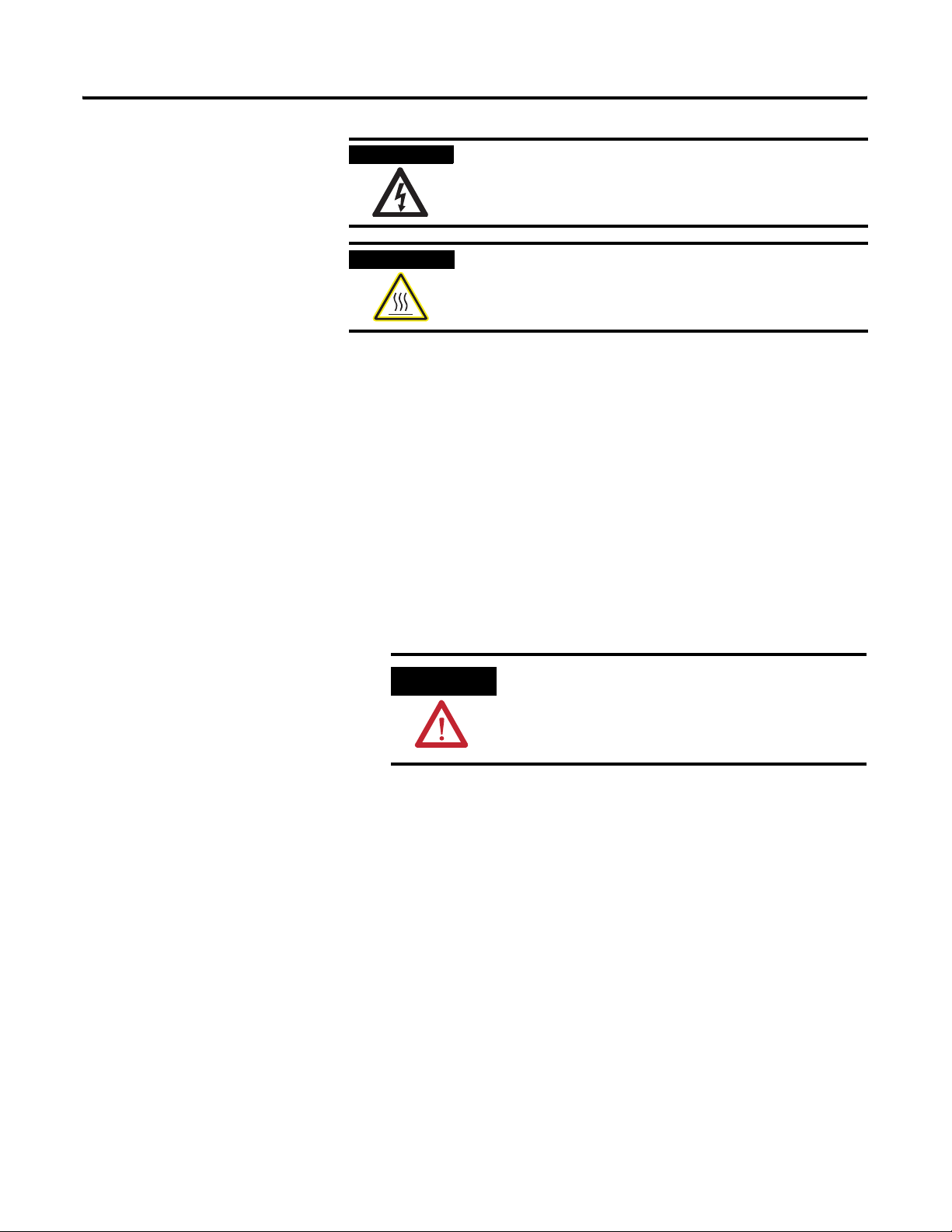
Disconnect the Terminal
SHOCK HAZARD
BURN HAZARD
The following tools are required for installation:
• socket driver with 7 mm (M4) deep socket
• small slotted screwdriver
• torque wrench capable of 1.13 Nm (10 in-lb)
1. Disconnect power at the source and remove the power cord
from the MicroView terminal.
Labels may be located on or inside the equipment (e.g.,
drive or motor) to alert people that dangerous voltage may
be present.
Labels may be located on or inside the equipment (e.g.,
drive or motor) to alert people that surfaces may be
dangerous temperatures.
Remove the Existing Terminal
2. Disconnect all communication cables from the terminal
ATTENTION
1. Remove the mounting nuts that secure the terminal in the panel.
2. Slide the existing terminal out from panel.
Make sure the power cord of the MicroView
terminal is disconnected and that all cables
have been disconnected from the terminal.
Publication 2711-IN051A-EN-P - September 2005
Page 3

MicroView (Bulletin 2707) to PanelView 300 Micro (Bulletin 2711) Adapter Plate 3
Install the Adapter Plate
Mount the PanelView 300 Micro
The following steps provide instructions for installing the adapter
plate in an existing MicroView panel opening.
1. Cut and drill the appropriate mounting holes in the enclosure or
panel.
2. Remove two mounting nuts from the hardware bag provided
with the product (six mounting nuts provided).
3. Position the adapter plate in the panel or enclosure mounting
hole.
4. Install nuts and alternately tighten the nuts to a torque of
1.13 Nm (10 in-lb).
The following instructions provide panel cutout dimensions for the
PanelView 300 Micro in an existing enclosure for the MicroView.
The PanelView 300 Micro mounts in the adapter cutout. When it is
properly installed, the faceplate provides a NEMA Type 4 rating. To
install the PanelView 300 Micro:
Additional Resources
1. Remove the six mounting nuts from the hardware bag provided
with the product.
2. Position the PanelView 300 Micro in the adapter plate.
TIP
3. Install nuts and alternately tighten the nuts to a torque of
1.13 Nm (10 in-lb).
For more information regarding the PanelView 300 Micro:
Publication Name Publication Number
PanelView 300 MicroView Terminals
Installation Instructions
Standard PanelView Operator Terminal User
Manual
The adapter plate and unit have mounting
gaskets. You need to press them against the
enclosure before installing the nuts.
2711-IN008
2711-UM014
Publication 2711-IN051A-EN-P - September 2005
Page 4

Panel Cutout Dimensions
All dimensions are in millimeters (inches).
144.3
(5.68)
4.5
(0.177)
PanelView 300 Micro
mounting hole.
Adapter plate
mounting hole.
Cut on dashed line.
Dashed lines indicate the
opening for the
PanelView 300 Micro in the
adapter plate.
Solid lines indicate existing
opening for the MicroView in
the enclosure.
7.87 (0.31)
PanelView 300 Micro
mounting hole.
53.8
(2.12)
99
(3.90)
PanelView 300 Micro
mounting hole.
PanelView 300 Micro
mounting hole.
Adapter plate
mounting hole.
112.3
(4.42)
Publication 2711-IN051A-EN-P - September 2005 4 PN 41061-366-01(1)
Copyright © 2005 Rockwell Automation, In c. All rights reserved. Printed in the U.S.A.
 Loading...