

Page 1

Mounting Clips
Catalog Number 2711-NP1
Installation Instructions
Inside...
English ..............................................................................................................3
Français.............................................................................................................4
Deutsch.............................................................................................................5
Español .............................................................................................................6
Italiano..............................................................................................................7
1 Publication 2711-2.12
Page 2
2 Mounting Clips
Important User Information
Solid state equipment has operational characteristics differing from those of
electromechanical equipment. Safety Guidelines for the Application,
Installation and Maintenance of Solid State Controls (Publication SGI-1.1
available from your local Rockwell Automation sales office or online at
http://www.ab.com/manuals/gi) describes some important differences
between solid state equipment and hard-wired electromechanical devices.
Because of this difference, and also because of the wide variety of uses for
solid state equipment, all persons responsible for applying this equipment
must satisfy themselves that each intended application of this equipment is
acceptable.
In no event will Rockwell Automation, Inc. be responsible or liable for
indirect or consequential damages resulting from the use or application of
this equipment.
The examples and diagrams in this manual are included solely for illustrative
purposes. Because of the many variables and requirements associated with
any particular installation, Rockwell Automation, Inc. cannot assume
responsibility or liability for actual use based on the examples and diagrams.
No patent liability is assumed by Rockwell Automation, Inc. with respect to
use of information, circuits, equipment, or software described in this manual.
Reproduction of the contents of this manual, in whole or in part, without
written permission of Rockwell Automation, Inc. is prohibited.
Throughout this manual, when necessary we use notes to make you aware of
safety considerations.
WARNING
IMPORTANT
ATTENTION
SHOCK HAZARD
BURN HAZARD
Identifies information about practices or circumstances
that can cause an explosion in a hazardous environment,
which may lead to personal injury or death, property
damage, or economic loss.
Identifies information that is critical for successful
application and understanding of the product.
Identifies information about practices or circumstances
that can lead to personal injury or death, property
damage, or economic loss. Attentions help you:
• identify a hazard
• avoid a hazard
• recognize the consequence
Labels may be located on or inside the equipment (e.g.,
drive or motor) to alert people that dangerous voltage may
be present.
Labels may be located on or inside the equipment (e.g.,
drive or motor) to alert people that surfaces may be
dangerous temperatures.
Publication 2711-2.12
Page 3
Installation Instructions
Mounting Clips
Catalog Number 2711-NP1
English
The package of mounting clips (Catalog No. 2711–NP1) contains 10
clips. Use these clips to mount the following:
• PanelView 1400 Operator Terminal (requires 10 clips)
• 6180 Industrial Computer (requires 10 clips)
• 14 inch Industrial Monitors (requires 6 clips)
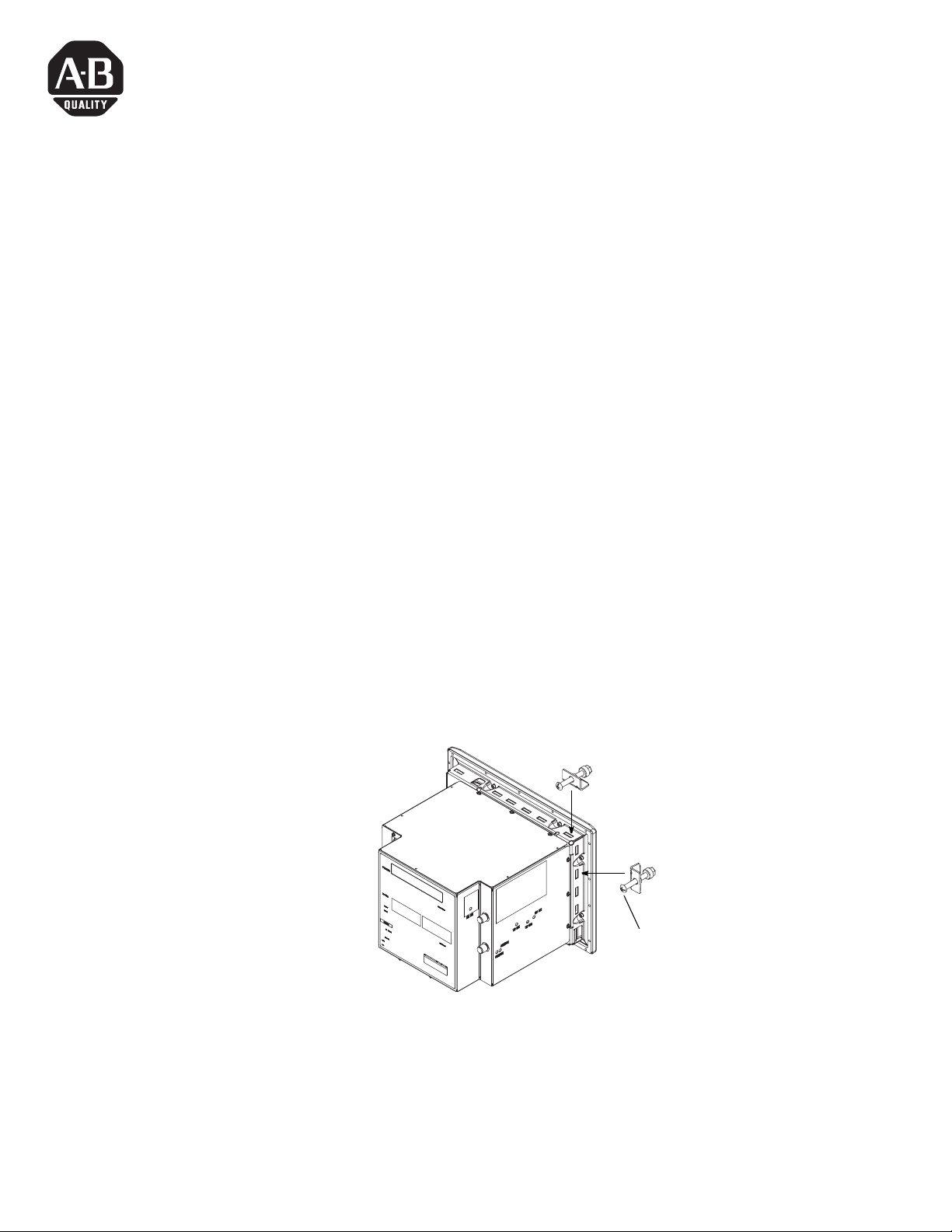
Mounting Clip Installation
1. Refer to the installation instructions provided with the operator
terminal, monitor, or industrial computer.
2. Clips are positioned in the chassis mounting slots. Tighten the
mounting clip using the screwdriver slot on the clip. Refer to the
device’s installation instructions for specific torque values and
tightening sequences.
Screwdriver slot for tightening clip
Aquí se muestra el PanelView 1400, otros dispositivos son
similares
3 Publication 2711-2.12
Page 4

Notice d’installation
Attaches de fixation
Catalog Number 2711-NP1
Français
Ce paquet d’attaches de fixation (référence 2711-NP1) contient dix
attaches. Utiliser ces attaches pour le montage d’un :
• ordinateur industriel 6180 (10 attaches)
• ordinateur industriel 6180 (10 attaches)
• moniteur industriel avec écran de 14 pouces (6 attaches)
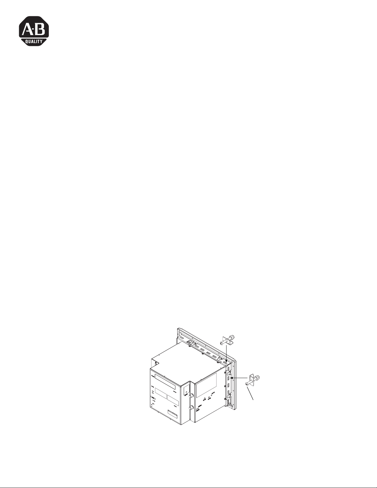
Installation des attaches de fixation
1. Se reporter à la notice d’installation fournie avec le terminal
opérateur, le moniteur ou l’ordinateur industriel.
2. Les attaches sont placées dans les encoches du châssis. Elles
sont munies d’une tête fendue pour le serrage. Se reporter aux
notices d’installation des appareils pour les valeurs spécifiques
de couple et d’ordre de serrage.
Tête fendue pour le serrage
Ici, PanelView 1400. Similaire pour les autres appareils.
4 Publication 2711-2.12
Page 5
Installationsanleitung
Montageklammern
Catalog Number 2711-NP1
Deutsch
Dieses Paket mit Montageklammern (Katalognr. 2711–NP1) enthält 10
Klammern. Diese Klammern werden für die Montage der folgenden
Geräte verwendet:
• PanelView 1400 Bedienerterminal (benötigt 10 Klammern)
• 6180 Industrie-Computer (benötigt 10 Klammern)
• 14 Zoll Industrie-Monitor (benötigt 6 Klammern)
Installation der Montageklammern
1. Beziehen Sie sich auf die Installationsanweisungen, die Sie mit
dem Bedienerterminal, Monitor oder Industrie-Computer
bekommen.
2. Die Klammern werden in den Chassismontageschlitzen
positioniert. Befestigen Sie die Montageklammern mit
Verwendung des Schraubendreher- schlitzes auf der Klammer.
Beziehen Sie sich auf die Installations- anweisungen des Gerätes
für ein spezifisches Drehmoment und die
Befestigungsreihenfolge.
Schraubendreherschiltz zur Befestigung
der Klammer.
PanelView 1400 gezeigt (andere Geräte sind ähnlich)
5 Publication 2711-2.12
Page 6

Instrucciones de instalación
Clips de montaje
Catalog Number 2711-NP1
Español
El paquete de clips de montaje (No. de catálogo 2711–NP1) contiene
10 clips. Usar estos clips para montar lo siguiente
• Terminal de operador PanelView 1400 (requiere 10 clips)
• Computadora industrial 6180 (requiere 10 clips)
• Monitor industrial de 14 pulgadas (requiere 6 clips)
Instalando los clips de montaje
1. Refiérase a las instrucciones de instalación proporcionadas con
el terminal de operador, monitor o computadora industrial.
2. Los clips se posicionan en las ranuras de montaje del chasis.
Apretar los clips de montaje usando la ranura de destornillador
del clip. Refiérase a las instrucciones de instalación para valores
específicos de torsión y secuencias de apretar.
Ranura de destomillador para apretar
el clip
PanelView 1400 shown, other devices are similar.
6 Publication 2711-2.12
Page 7

Istruzioni per l’installazione
Ganci di montaggio
Catalog Number 2711-NP1
Italiano
La confezione con i ganci di montaggio (N. Catalogo 2711–NP1)
contiene 10 ganci. Usare questi ganci per montare i seguenti terminali:
• Terminale Operatore PanelView 1400 (richiede 10 ganci)
• Computer industriale 6180 (richiede 10 ganci)
• Monitor industriali da 14 pollici (richiedono 6 ganci)
Installazione dei ganci di montaggio
1. Consultare la guida per l’installazione fornita con il terminale
operatore, il monitor, o il computer industriale.
2. I ganci vengono posizionati nelle fessure di montaggio del
telaio. Stringere i ganci di montaggio servendosi dell’apposita
fessura per il cacciavite. Consultare la guida per l’installazione
del dispositivo, per avere le specifiche sequenze e i valori di
serraggio.
Fessura per il cacciavite
PanelView 1400, altri dispositivi sono simili
7 Publication 2711-2.12
Page 8
Rockwell Automation Support
Rockwell Automation provides technical information on the web to assist you in using its products. At
http://support.rockwellautomation.com, you can find technical manuals, a knowledge base of FAQs, technical and
application notes, sample code and links to software service packs, and a MySupport feature that you can customize
to make the best use of these tools.
For an additional level of technical phone support for installation, configuration and troubleshooting, we offer
TechConnect Support programs. For more information, contact your local distributor or Rockwell Automation
representative, or visit http://support.rockwellautomation.com.
Installation Assistance
If you experience a problem with a hardware module within the first 24 hours of installation, please review the
information that's contained in this manual. You can also contact a special Customer Support number for initial help
in getting your module up and running:
United States 1.440.646.3223
Monday – Friday, 8am – 5pm EST
Outside United States Please contact your local Rockwell Automation representative for any technical support issues.
New Product Satisfaction Return
Rockwell tests all of its products to ensure that they are fully operational when shipped from the manufacturing
facility. However, if your product is not functioning and needs to be returned:
United States Contact your distributor. You must provide a Customer Support case number (see phone number
above to obtain one) to your distributor in order to complete the return process.
Outside United States Please contact your local Rockwell Automation representative for return procedure.
Publication 2711-2.12 - March 1997 8 PN 40061-212-01(D)
Supersedes Publication 2711-2.12 - October 1995 Copyright © 1997 Rockwell Automation, Inc . All rights reserved. Printed in the U.S.A.
ö
 Loading...