

Page 1
Installation Instructions
IMPORTANT
Kinetix 5500 Capacitor Module
Catalog Number 2198-CAPMOD-1300
Topi c Pag e
About the Kinetix 5500 Capacitor Module 1
Important User Information 2
Before You Begin 3
Install the Kinetix 5500 Capacitor Module 3
Connector Data 5
Wiring Requirements 6
Additional Resources 7
About the Kinetix 5500 Capacitor Module
The Kinetix 5500 capacitor module provides 1360 μF capacitance for applications where the
Kinetix 5500 internal shunt module capacity is exceeded. The capacitor module can be used
alone or in combination with a Bulletin 2097 external shunt module for applications with
excessive regenerative energy.
The Kinetix 5500 capacitor module is an option for Bulletin 2198 servo drive configurations
with 200V or 400V-class operation.
Use the 2198-CAPMOD-1300 capacitor module in Kinetix 5500 drive configurations where
DC bus power is shared through the shared-bus connection system. You cannot use the
capacitor module in configurations where only AC input power is shared.
Refer to the Kinetix 5500 Servo Drives User Manual, publication 2198-UM001
information on wiring, applying power, troubleshooting , and integration with ControlLogix® or
CompactLogix™ controllers.
, for detailed
Page 2
2 Kinetix 5500 Capacitor Module
Important User Information
Solid state equipment has operational characteristics differing from those of electromechanical equipment. Safety Guidelines for
the Application, Installation and Maintenance of Solid State Controls (Publication SGI-1.1
Automation sales office or online at http://www.rockwellautomation.com/literature/
between solid state equipment and hard-wired electromechanical devices. Because of this difference, and also because of the
wide variety of uses for solid state equipment, all persons responsible for applying this equipment must satisfy themselves that
each intended application of this equipment is acceptable.
In no event will Rockwell Automation, Inc. be responsible or liable for indirect or consequential damages resulting from the use or
application of this equipment.
The examples and diagrams in this manual are included solely for illustrative purposes. Because of the many variables and
requirements associated with any particular installation, Rockwell Automation, Inc. cannot assume responsibilit y or liability for
actual use based on the examples and diagrams.
No patent liability is assumed by Rockwell Automation, Inc. with respect to use of information, circuits, equipment, or software
described in this manual.
Reproduction of the contents of this manual, in whole or in part, without written permission of Rockwell Automation, Inc., is
prohibited.
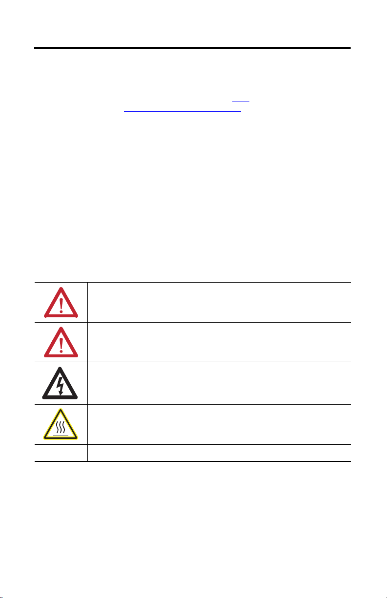
Throughout this manual, when necessary, we use notes to make you aware of safety considerations.
WARNIN G: Identifies information about practices or circumstances that can cause an explosion in a
hazardous enviro nment, which may lead to personal injury or death, property damage, or economic loss.
available from your local Rockwell
) describes some important differences
ATTENTION: Identifies information about practices or circumstances that can lead to personal injury or
death, property damage, or economic loss. Attentions help you identify a hazard, avoid a haz ard and
recognize the consequences.
SHOCK HAZARD: Labels may be on or insid e the equipment, for example, drive or motor, to alert people
that dangerous voltage may be present.
BURN HAZARD: Labels may be on or inside the equipment, for example, drive or motor, to alert people
that surfaces may reach dangerous temperatures.
IMPORTANT
Identifies information that is critical for successful application and understanding of the product.
Publication 2198-IN004A-EN-P - October 2012
Page 3
Kinetix 5500 Capacitor Module 3
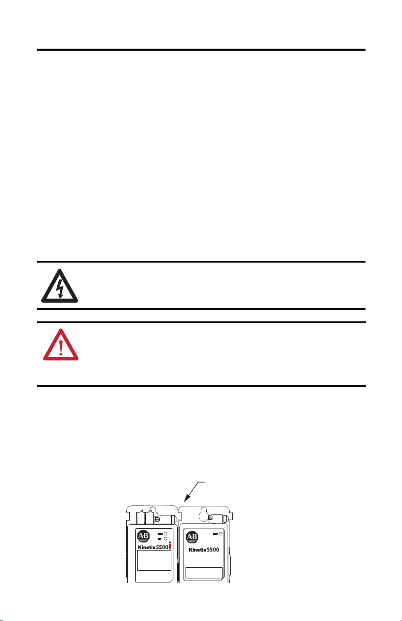
2198-Hxxx-ERS Drive
(front view)
Zero-s tack Tab
and Cutout Engaged
2198-CAPMOD-1300 Capacitor Module
(front view)
Before You Begin
Remove all packing material, wedges, and braces from within and around the components. After
unpacking, check the item nameplate catalog number against the purchase order.
The Kinetix 5500 servo drives are shipped with the following:
• Wiring plug for the module status (MS) connector
• These installation instructions, publication 2198-IN004
Install the Kinetix 5500 Capacitor Module
These procedures assume that you have prepared your panel, mounted your Kinetix 5500 servo
drives, and understand how to bond your system. For installation instructions regarding
equipment and accessories not included here, refer to the instructions that came with those
products.
SHOCK HAZARD: To avoid the hazard of electrical shock, perform all mounting and wiring of
the Kinetix 5500 drive modules prior to applying power. Once power is applied, connector
terminals may have voltage present even when not in use.
ATTENTION: Plan the installation of your system so that you can perform all cutting, drilling,
tapping, and welding with the system removed from the enclosure. Because the system is of
open type construction, be careful to keep any metal debris from falling into it. Metal debris or
other foreign matter can become lodged in the circuitry, which can result in damage to
components.
Zero-stack Tab and Cutout
Engaging the zero-stack tab and cutout from drive-to-drive is required for shared-bus drive
systems and includes the Bulletin 2198 capacitor module. This is done to make sure the drive
connectors are spaced properly to accept the shared-bus connection system.
Figure 1 - Zero-stack Tab and Cutout Example
Publication 2198-IN004A-EN-P - October 2012
Page 4

4 Kinetix 5500 Capacitor Module
IMPORTANT
2198-Hxxx-ERS Drive System
(front view)
Frame 2 D rives
Frame 1 Drives
2198-CAPMOD-1300 Capacitor Module
(optional component)
Shared-bus Connection System
for DC Bus and 24V Control Power
Frame 3 D rive
Mount the Capacitor Module
Clearance requirements for the Kinetix 5500 capacitor module are identical to the drive
modules. Refer to the Kinetix 5500 Servo Drives User Manual, publication 2198-UM001
additional mounting information.
You can mount the capacitor modules to the right of any frame size, but are always rightmost in
any drive configuration.
Mount drives in descending order, left to right, according to frame size with capacitor
modules always mounted on the far right.
The shared-bus connection system is required for capacitor module installations.
Figure 2 - Kinetix 5500 Drive System Example with Capacitor Module
, for
Table 1 - Capacitor Module Support
Three-phase Operation
Drive Cat. No.
Frame Size
2198-H003-ERS
2198-H008-ERS
2198-H015-ERS
2198-H040-ERS
2198-H070-ERS 3 4
(1) Catalog number 2198-H003-ERS and any drive in standalone single-phase operation is not compatible with the Kinetix 5500
capacitor module.
(1)
1
(1)
(1)
0
242198-H025-ERS
N/A
The recommended mounting hardware is M4 (#8-32) steel bolts. Apply 2.0 N•m (17.7 lb•in)
maximum torque to each fastener.
Publication 2198-IN004A-EN-P - October 2012
Standalone Shared DC Shared AC/DC
Standalone
Single Phase
Operation
Number of capacitor modules connected, max
0
1
3
2
Shared AC/DC
Hybrid
Page 5

Kinetix 5500 Capacitor Module 5
2198-CAPMOD-1300
Capacitor Module
Dimensions are in mm (in.)
2198-CAPMOD-1300 Capacitor Module
(top view)
2198-CAPMOD-1300 Capacitor Module
(front view)
Item Description
1 Module status (MS) connector
2 Module status indicator
3 DC bus (DC) connector (under cover)
(1)
(1) DC bus connector ships with protective knock-out cover,
which can be removed for use in shared-bus configurations.
4 24V control input power (CP) connector
Product Dimensions
Capacitor modules have the same dimensions and drill pattern as frame 2 drives.
Figure 3 - Capacitor Module Dimensions
225
(8.86)
265
(10.43)
200
(7.87)
210
(8.27)
55
(2.16)
3.0
(0.12)
Connector Data
The Kinetix 5500 capacitor module is compatible with all 200V and 400V-class drive systems.
Figure 4 - Capacitor Module Features and Indicators
2
2
1
1
3
4
Publication 2198-IN004A-EN-P - October 2012
Page 6

6 Kinetix 5500 Capacitor Module
IMPORTANT
Table 2 - DC Bus (DC) Connector Pinout
DC Pin Description Signal
1
2DC+
DC bus connections
DC-
Table 3 - Control Input Power (CP) Connector Pinout
CP Pin Description Signal
1 24V power supply, customer-supplied 24V+
2 24V common 24V-
Table 4 - Module Status (MS) Connector Pinout
MS Pin Description Signal
1 Module status relay output + RELAY+
2 Module status relay output - RELAY-
Wiring Requirements
The National Electrical Code and local electrical codes take precedence over the values and
methods provided.
Table 5 - Capacitor Module Wiring Requirements
Connector
Description
Module Status
indicator
PELV/SELV
24V power
DC bus power
(1) 24V control power and DC bus connect ions are always made from drive-to-drive over the shared-bus connection system. These te rminals do not
receive d iscrete wires.
Pin Signal
MS-1
MS-2
CP-1
CP-2
DC-1
DC-2
RELAY+
RELAY-
24V+
24V-
DCDC+
Recommended
Wire Size
2
(AWG)
mm
0.14…1.5
(28…16)
(1)
N/A
(1)
N/A
ATTENTION: To avoid personal injury and/or equipment damage, observe the following:
• Make sure installation complies with specifications regarding wire types, conductor sizes,
branch circuit protection, and disconnect devices. The National Electrical Code (NEC) and local
codes outline provisions for safely installing electrical equipment.
• Use power connectors for connection purposes only. Do not use them to turn the unit on and off.
• Ground shielded power cables to prevent potentially high voltages on the shield.
Publication 2198-IN004A-EN-P - October 2012
Strip Length
mm (in.)
7.0 (0.28)
(1)
N/A
(1)
N/A
Tor que V alu e
N•m (lb•in)
0.22…0.25
(1.9…2.2)
(1)
N/A
(1)
N/A
Page 7

Ground Your Capacitor Module to the Subpanel
Braided Ground Straps
25.4 mm (1.0 in.) x 6.35 mm (0.25 in.)
Keep length as short as possible.
4
3
2
1
2198-CAPMOD-1300 Capacitor Module
(side view)
Item Description
1 Ground screw (green) 2.0 N•m (17.5 lb-in), max
2 Braided ground strap (customer supplied)
3 Ground grid or power distribution ground
4 Bonded cabinet ground bus (customer supplied)
Kinetix 5500 Capacitor Module 7
Ground Bulletin 2198 drives and 2198-CAPMOD-1300 capacitor modules to a bonded cabinet
ground bus with a braided ground strap or 4.0 mm
2
(12 AWG) copper wire.
Figure 5 - Connecting the Braided Ground Strap
Additional Resources
These documents contain additional information concerning related products from
Rockwell Automation.
Resource Description
Kinetix 5500 Servo Drives User Manual, publication 2198-UM001
Kinetix 300 Shunt Resistor Installation Instructions,
publication 2097-IN002
Industrial Automation Wiring and Grounding Guidelines,
publication 1770-4.1
Product Certifications website, http://www.ab.com
You can view or download publications at http://www.rockwellautomation.com/literature
order paper copies of technical documentation, contact your local Allen-Bradley distributor or
Rockwell Automation sales representative.
Provides information on installing, configuring, start up, and
troubleshooting your Kinetix 5500 servo drive system.
Provides information on installing and wiring Kinetix 300
external shunt resistors.
Provides general guidelines for installing a Rockwell
Automation industrial system.
Provides declarations of conformity, certificates, and other
certification details.
Publication 2198-IN004A-EN-P - October 2012
. To
Page 8

Rockwell Automation Support
Rockwell Automation provides tec hnical information on the Web to assist you in using its products.
At http://www.rockwellautomation.com/support
and links to software service packs, and a MySupport feature that you can customize to make the best use of these tools. You can
also visit our Knowledgebase at http://www.rockwellautomation.com/knowledgebase
chat and forums, software updates, and to sign up for product notification updates.
For an additional level of technical phone support for installation, configuration and troubleshooting, we offer TechConnect
support programs. For more information, contact your local distributor or Rockwell Automation representative, or visit
http://www.rockwellautomation.com/support/
Installation Assistance
If you experience a problem within the first 24 hours of installation, please review the information that's contained in this manual.
You can also contact a special Customer Support number for initial help in getting your product up and running.
United States or Canada 1.440.6 46.3434
Outside United States or
Canada
Use the Wor ldwi de Loc ator
http://www.rockwellautomation.com/support/americas/phone_en.html
Rockwell Automation representative.
New Product Satisfaction Return
Rockwell Automation tests all of its products to ensure that they are fully operational when shipped from the manufacturing
facility. However, if your product is not functioning and needs to be returned, follow these procedures.
United States
Outside United States Please contact your local Rockwell Automation representative for the return procedure.
Contact your distributor. You must provide a Customer Support case number (call the phone number
above to obtain one) to your distributor to complete the return process.
, you can find technical manuals, technical and application notes, sample code
for FAQs, technical information, support
sm
.
at
, or contact your local
Documentation Feedback
Your comments will help us serve your documentation needs better. If you have any suggestions on how to improve this document,
complete this form, publication RA-DU002
Allen-Bradley, CompactLogix, ControlLogix, Kinetix, Rockwell Soft ware, Rockwell Automation, and TechConnect are trademarks of
Rockwell Automation, Inc.
Trademarks not belonging to Rockwell Automation are property of their respective companies.
Rockwell Otomasyon Ticaret A.Ş., Kar Plaza İş Merkezi E Blok Kat:6 34752 İçerenköy, İstanbul, Tel: +90 (216) 5698400
Publication 2198-IN004A-EN-P - October 2012 PN-176296
, available at http://www.rockwellautomation.com/literature/.
Copyright © 2012 Rockwell Automation, Inc. All rights reserved. Printed in the U.S.A.
 Loading...