

Page 1
Installation Instructions
PowerFlex® 700L
Liquid-to-Liquid Heat Exchanger
Control Board Replacement
ATTENTION: To avoid an electric shock hazard and prevent
thermal damage, ensure that all power to the drive power module
!
and
heat exchanger has been removed before performing any
steps of these instructions. Since control wires from the drive are
connected to the heat exchanger control board, it is necessary to
remove power from the drive as well as the heat exchanger.
ATTENTION: To avoid an electric shock hazard, verify that the
voltage on the drive power module bus capacitors has completely
!
discharged before performing any work on the heat exchanger.
After removing power to the drive power module, wait 5 minutes
for the bus capacitors to discharge. Remove the front cover of the
drive power module (complete cover for Frame 2 drives or lower
front cover for Frame 3A and 3B drives). Measure the DC bus
voltage at the DC+ TESTPOINT and DC- TESTPOINT sockets
on the front of the drive power module. The voltage must be zero.
What This Kit Includes
Tools That You Need
ATTENTION: This heat exchanger control board contains ESD
(Electrostatic Discharge) sensitive parts and assemblies. Static
!
control precautions are required when installing, testing,
servicing or repairing this assembly. Component damage may
result if ESD control procedures are not followed. If you are not
familiar with static control procedures, refer to Allen-Bradley
publication 8000-4.5.2, “Guarding Against Electrostatic
Damage” or any other applicable ESD protection handbook.
• One replacement control board
• Standard flat blade screwdriver
• #2 Phillips screwdriver
Page 2
2 PowerFlex® 700L Liquid-to-Liquid Heat Exchanger Control Board Replacement
Step 1: Removing Power from the Drive Power Module
ATTENTION: To avoid an electric shock hazard, verify that the
voltage on the drive power module bus capacitors has completely
!
discharged before performing any work on the heat exchanger.
After removing power to the drive power module, wait 5 minutes
for the bus capacitors to discharge. Remove the front cover of the
drive power module (complete cover for Frame 2 drives or lower
front cover for Frame 3A and 3B drives). Measure the DC bus
voltage at the DC+ TESTPOINT and DC- TESTPOINT sockets
on the front of the drive power module. The voltage must be zero.
Remove power before making or breaking cable connections.
When you remove or insert a cable connector with power
applied, an electrical arc may occur, which can cause personal
injury or property damage by:
• sending an erroneous signal to your system’s field devices,
causing unintended machine motion
• causing an explosion in a hazardous environment
Electrical arcing causes excessive wear to contacts on both the
module and its mating connector. Worn contacts may create
electrical resistance.
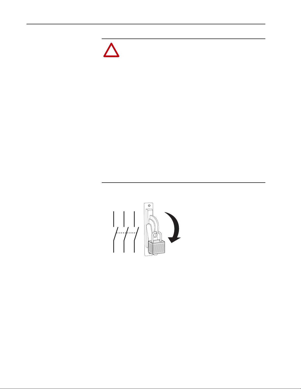
A. Turn off and lock out input power. Wait 5 minutes.
L1 L2 L3
B. Verify that there is no voltage at the drive power module’s input power
terminals.
C. Remove the front cover of the drive power module (complete cover for
Frame 2 drives or lower front cover for Frame 3A and 3B drives).
D. Measure the DC bus voltage at the DC+ TESTPOINT and DC-
TESTPOINT sockets on the front of the drive power module chassis.
The voltage must be zero.
I
O
Page 3

Step 2: Removing Power from the Heat Exchanger
PowerFlex® 700L Liquid-to-Liquid Heat Exchanger Control Board Replacement 3
ATTENTION: Remove power before making or breaking cable
connections. When you remove or insert a cable connector with
!
power applied, an electrical arc may occur, which can cause
personal injury or property damage by:
• sending an erroneous signal to your system’s field devices,
causing unintended machine motion
• causing an explosion in a hazardous environment
Electrical arcing causes excessive wear to contacts on both the
module and its mating connector. Worn contacts may create
electrical resistance.
A. Turn off and lock out input power.
Step 3: Opening the Electrical Box Door
L1 L2 L3
B. Verify that there is no voltage at the heat exchanger’s input power
terminals.
Using the flat blade screwdriver, turn the locking mechanism on the
electrical box door counterclockwise one-quarter turn and open the door.
I
O
Electrical Box
Locking
Mechanism
Page 4

4 PowerFlex® 700L Liquid-to-Liquid Heat Exchanger Control Board Replacement
Step 4: Removing the Light Pipes
A. Pull out the gray plastic grommet that secures each of the two (2) light
pipes.
Grommets
Control Board
Light Pipes
Light Pipe Bracket
B. Pull out each light pipe from its connector on the board.
Electrical Box
(cover removed)
J1
J7
J8
Light Pipes
Control Board
J2
J5
J6
Step 5: Removing the Old Control Board
A. Use the table below to note the settings of dipswitches S1 and S2.
SW8 SW7 SW6 SW5 SW4 SW3 SW2 SW1
S1
S2
B. Note the position of the J2 voltage selection jumper.
1
2
3
4
5
6
7
8
9
1
2
3
4
5
6
7
8
9
J2
1
9
FU1
230 VAC
Operation
Plug Position
115 VAC
Operation
Plug Position
Page 5

PowerFlex® 700L Liquid-to-Liquid Heat Exchanger Control Board Replacement 5
C. On the control board, pull out the removable terminal block connectors
from J1, J5, J6, J7, and J8.
D. Hold the control board in place while unscrewing the (4) mounting
screws from the corners of the control board. Save the screws for
installation of the new control board.
ATTENTION: HOT surfaces can cause severe burns. Do not
touch the surface of the power transformer on the control board
!
while removing the control board. After disconnecting power to
the heat exchanger, allow time for cooling.
E. Remove the old control board.
F. Remove each control board connector for each light pipe by pushing in
its tabs on the back of the board and gently pulling the connector out
from the front.
Mounting Plate
Step 6: Installing the New Control Board
Step 7: Installing the Light Pipes
Light Pipes
Control Board
Connectors
Light Pipe
Bracket
Install the new control board in reverse order of Step 5. Be sure to set the J2
voltage jumper and S1 and S2 dip switch settings as noted during removal
of the old control board.
Install the light pipes in reverse order of Step 4.
Page 6

A
A
U.S. Allen-Bradley Drives Technical Support - Tel: (1) 262.512.8176, Fax: (1) 262.512.2222, Email: support@drives.ra.rockwell.com, Online: www.ab.com/support/abdrives
www.rockwellautomation.com
Power, Control and Information Solutions Headquarters
mericas: Rockwell Automation, 1201 South Second Street, Milwaukee, WI 53204-2496 USA, Tel: (1) 414.382.2000, Fax: (1) 414.382.4444
Europe/Middle East/Africa: Rockwell Automation, Vorstlaan/Boulevard du Souverain 36, 1170 Brussels, Belgium, Tel: (32) 2 663 0600, Fax: (32) 2 663 0640
sia Pacific: Rockwell Automation, Level 14, Core F, Cyberport 3, 100 Cyberport Road, Hong Kong, Tel: (852) 2887 4788, Fax: (852) 2508 1846
Publication 20L-IN006A-EN-P – April, 2007 P/N 181737-P01
Copyright © 2007 Rockwell Automation, Inc. All rights reserved. Printed in USA.
 Loading...