

Page 1

PowerFlex 700L
Active Converter Power Module
USER MANUAL
Firmware Version 3.xxx
Page 2
Important User
Information
Solid state equipment has operational characteristics differing from those of
electromechanical equipment. Safety Guidelines for the Application, Installation and
Maintenance of Solid State Controls (Publication SGI-1.1 available from your local
Rockwell Automation sales office or online at
literature) describes some important differences between solid state equipment and
hard-wired electromechanical devices. Because of this difference, and also because of
the wide variety of uses for solid state equipment, all persons responsible for applying
this equipment must satisfy themselves that each intended application of this
equipment is acceptable.
In no event will Rockwell Automation, Inc. be responsible or liable for indirect or
consequential damages resulting from the use or application of this equipment.
The examples and diagrams in this manual are included solely for illustrative
purposes. Because of the many variables and requirements associated with any
particular installation, Rockwell Automation, Inc. cannot assume responsibility or
liability for actual use based on the examples and diagrams.
No patent liability is assumed by Rockwell Automation, Inc. with respect to use of
information, circuits, equipment, or software described in this manual.
Reproduction of the contents of this manual, in whole or in part, without written
permission of Rockwell Automation, Inc. is prohibited.
Throughout this manual, when necessary we use notes to make you aware of safety
considerations.
http://www.rockwellautomation.com/
WARNING: Identifies information about practices or
circumstances that can cause an explosion in a hazardous
!
environment, which may lead to personal injury or death, property
damage, or economic loss.
Important: Identifies information that is critical for successful application and
understanding of the product.
ATTENTION: Identifies information about practices or
circumstances that can lead to personal injury or death, property
!
damage, or economic loss. Attentions help you identify a hazard,
avoid a hazard, and recognize the consequences.
Shock Hazard labels may be located on or inside the equipment
(e.g., drive or motor) to alert people that dangerous voltage may be
present.
Burn Hazard labels may be located on or inside the equipment
(e.g., drive or motor) to alert people that surfaces may be at
dangerous temperatures.
Allen-Bradley, PowerFlex, DriveExplorer, DriveExecutive, and DPI are either registered trademarks or trademarks of Rockwell Automation, Inc.
PowerFlex 700L Active Converter Power Module User Manual
Page 3

Summary of Changes
The information below summarizes the changes resulting from the firmware
v3.001 upgrade to this manual since its last release (June, 2006):
Description of New or Updated Information Page(s)
To all pages, added a new footer containing:
• Publication description (1st line).
• Publication number hyperlink underlined in blue (2nd line) linking to the date of the
publication on the back cover.
The back cover publication date line hyperlinks to the newest version of the publication
on Rockwell Automation’s Literature Library web site.
Added new information about the Active Converter operating as a Coupled unit (DPI
SLAVE) or as a Stand Alone unit (DPI MASTER).
Changed the following for Parameter 051 - [Option Select]:
• Bit 6 changed from “Reserved” to “VC Inverter.”
• Bit 7 changed from “Reserved” to “Prechg Cntrl.”
• The default changed from “xxxx xxxx xx00 0001” to “xxxx xxxx 0000 0001.”
Added new Parameter 105 - [Regen I Lmt]. 3-9
Changed Parameter 153 - [CML Bandwidth] maximum value from “3000 Rad/sec” to
“4000 Rad/sec.”
Changed the description for Parameter 157 - [PF Bandwidth] to include that it should be
used only when unbalanced voltage compensation is enabled in Parameter 051 [Option Select].
Changed Parameter 162 - [Capacitance] maximum value from “32767 µF” to “65535 µF.” 3-12
Added new Parameter 170 - [Bus Capacitance]. 3-12
Added new Bit 11 (High DC Link) to Parameter 214 - [Start Inhibit]. 3-14
Changed Parameter 238 - [Fault Config] default from “xxxx xxx1 1110 1100” to
“xxxx xxx1 0110 1100.”
Added two new parameter groups which are only displayed and available in the
Communication File when the Converter is operated as a Stand Alone unit:
• Masks and Owners Group
– Parameter 340 - [Logic Mask]
– Parameter 341 - [Start Mask]
– Parameter 342 - [Fault Clr Mask]
– Parameter 343 - [Stop Owner]
– Parameter 344 - [Start Owner]
– Parameter 345 - [Fault Clr Owner]
• Security Group
– Parameter 346 - [Port Mask Act]
– Parameter 347 - [Write Mask Cfg]
– Parameter 348 - [Write Mask Act]
– Parameter 349 - [Logic Mask Act]
Added the following new fault codes:
• 70 – FiltCap Contactr
• 71 – Port 1 Adapter
• 72 – Port 2 Adapter
• 73 – Port 3 Adapter
• 74 – Port 4 Adapter
• 75 – Port 5 Adapter
• 76 – Port 6 Adapter
• 81 – Port 1 DPI Loss
• 82 – Port 2 DPI Loss
• 83 – Port 3 DPI Loss
• 84 – Port 4 DPI Loss
• 85 – Port 5 DPI Loss
• 86 – Port 6 DPI Loss
Throughout
Manual
1-6
3-6
3-11
3-11
3-15
3-18
4-3
PowerFlex 700L Active Converter Power Module User Manual
Publication PFLEX-UM002D-EN-P
Page 4

soc-ii Summary of Changes
PowerFlex 700L Active Converter Power Module User Manual
Publication PFLEX-UM002D-EN-P
Page 5

Preface Overview
Who Should Use this Manual? . . . . . . . . . . . . . . . . . . . . . . . . . . . . . . . . . . . . . . . . . . . . . P-1
What Is Not in this Manual . . . . . . . . . . . . . . . . . . . . . . . . . . . . . . . . . . . . . . . . . . . . . . . . P-1
LPM20 Liquid-Cooled AC Drive Installation . . . . . . . . . . . . . . . . . . . . . . . . . . . . . . . P-1
PowerFlex 700L Liquid-Cooled AC Drive Information . . . . . . . . . . . . . . . . . . . . . . . P-1
PowerFlex 700 Vector Control Information (standard) . . . . . . . . . . . . . . . . . . . . . . . . P-1
PowerFlex 700S Phase II Control Information (optional) . . . . . . . . . . . . . . . . . . . . . . P-2
Reference Materials . . . . . . . . . . . . . . . . . . . . . . . . . . . . . . . . . . . . . . . . . . . . . . . . . . . . . P-2
Publications . . . . . . . . . . . . . . . . . . . . . . . . . . . . . . . . . . . . . . . . . . . . . . . . . . . . . . . . . . P-2
Allen-Bradley Drives Technical Support . . . . . . . . . . . . . . . . . . . . . . . . . . . . . . . . . . . P-2
Manual Conventions . . . . . . . . . . . . . . . . . . . . . . . . . . . . . . . . . . . . . . . . . . . . . . . . . . . . . P-2
General Precautions . . . . . . . . . . . . . . . . . . . . . . . . . . . . . . . . . . . . . . . . . . . . . . . . . . . . . P-3
Chapter 1 Installation/Wiring
Removing the Active Converter Power Module Covers . . . . . . . . . . . . . . . . . . . . . . . . . 1-2
Removing the Active Converter Control Cassette . . . . . . . . . . . . . . . . . . . . . . . . . . . . . . 1-2
Frame 2 and 3A Drives . . . . . . . . . . . . . . . . . . . . . . . . . . . . . . . . . . . . . . . . . . . . . . . . . 1-2
Frame 3B Drives . . . . . . . . . . . . . . . . . . . . . . . . . . . . . . . . . . . . . . . . . . . . . . . . . . . . . . 1-3
Wiring the Active Converter Control Cassette I/O Terminals . . . . . . . . . . . . . . . . . . . . . 1-4
I/O Terminal Blocks . . . . . . . . . . . . . . . . . . . . . . . . . . . . . . . . . . . . . . . . . . . . . . . . . . . 1-5
Using the Active Converter as a Coupled Unit vs. Standalone Unit. . . . . . . . . . . . . . . 1-6
Setting the DPI MASTER/SLAVE Switch (SW1) . . . . . . . . . . . . . . . . . . . . . . . . . . . . 1-8
Connecting an Active Converter Power Module to an Inverter Power Module . . . . . . . . 1-8
Frame 2 and 3A Drives . . . . . . . . . . . . . . . . . . . . . . . . . . . . . . . . . . . . . . . . . . . . . . . . . 1-8
Frame 3B Drives . . . . . . . . . . . . . . . . . . . . . . . . . . . . . . . . . . . . . . . . . . . . . . . . . . . . . . 1-8
Table of Contents
Chapter 2 Start Up
Establishing Communication as a Coupled Unit . . . . . . . . . . . . . . . . . . . . . . . . . . . . . . . 2-1
Accessing Active Converter Power Module Parameters. . . . . . . . . . . . . . . . . . . . . . . . 2-1
Verifying Feedback Parameters. . . . . . . . . . . . . . . . . . . . . . . . . . . . . . . . . . . . . . . . . . . 2-4
Exchanging Data . . . . . . . . . . . . . . . . . . . . . . . . . . . . . . . . . . . . . . . . . . . . . . . . . . . . . . 2-5
CIP Messages . . . . . . . . . . . . . . . . . . . . . . . . . . . . . . . . . . . . . . . . . . . . . . . . . . . . . . . . 2-7
Establishing Communication as a Stand Alone Unit . . . . . . . . . . . . . . . . . . . . . . . . . . . . 2-8
Accessing Active Converter Power Module Parameters. . . . . . . . . . . . . . . . . . . . . . . . 2-8
Verifying Feedback Parameters. . . . . . . . . . . . . . . . . . . . . . . . . . . . . . . . . . . . . . . . . . . 2-9
Converter Sequencing . . . . . . . . . . . . . . . . . . . . . . . . . . . . . . . . . . . . . . . . . . . . . . . . . . . 2-12
Run On Start . . . . . . . . . . . . . . . . . . . . . . . . . . . . . . . . . . . . . . . . . . . . . . . . . . . . . . . . 2-12
Run On PwrUp . . . . . . . . . . . . . . . . . . . . . . . . . . . . . . . . . . . . . . . . . . . . . . . . . . . . . . 2-13
Manual Cntrl . . . . . . . . . . . . . . . . . . . . . . . . . . . . . . . . . . . . . . . . . . . . . . . . . . . . . . . . 2-13
Start Inhibit . . . . . . . . . . . . . . . . . . . . . . . . . . . . . . . . . . . . . . . . . . . . . . . . . . . . . . . . . 2-13
Sequencing Precautions. . . . . . . . . . . . . . . . . . . . . . . . . . . . . . . . . . . . . . . . . . . . . . . . 2-13
Control Setup . . . . . . . . . . . . . . . . . . . . . . . . . . . . . . . . . . . . . . . . . . . . . . . . . . . . . . . . . 2-14
Current Limits . . . . . . . . . . . . . . . . . . . . . . . . . . . . . . . . . . . . . . . . . . . . . . . . . . . . . . . 2-14
Line Voltage Limits. . . . . . . . . . . . . . . . . . . . . . . . . . . . . . . . . . . . . . . . . . . . . . . . . . . 2-14
Frequency Limits. . . . . . . . . . . . . . . . . . . . . . . . . . . . . . . . . . . . . . . . . . . . . . . . . . . . . 2-15
Voltage Loop . . . . . . . . . . . . . . . . . . . . . . . . . . . . . . . . . . . . . . . . . . . . . . . . . . . . . . . . 2-15
Current Loop . . . . . . . . . . . . . . . . . . . . . . . . . . . . . . . . . . . . . . . . . . . . . . . . . . . . . . . . 2-16
PWM Carrier Synchronization . . . . . . . . . . . . . . . . . . . . . . . . . . . . . . . . . . . . . . . . . . 2-16
PowerFlex 700L Active Converter Power Module User Manual
Publication PFLEX-UM002D-EN-P
Page 6

ii Table of Contents
Converter Faults. . . . . . . . . . . . . . . . . . . . . . . . . . . . . . . . . . . . . . . . . . . . . . . . . . . . . . . . 2-17
Converter Faults as a Coupled Unit (DPI SLAVE) . . . . . . . . . . . . . . . . . . . . . . . . . . . 2-17
Displaying the Fault Text. . . . . . . . . . . . . . . . . . . . . . . . . . . . . . . . . . . . . . . . . . . . . . . 2-17
Resetting Converter Faults. . . . . . . . . . . . . . . . . . . . . . . . . . . . . . . . . . . . . . . . . . . . . . 2-18
Chapter 3 Programming and Parameters
About Parameters. . . . . . . . . . . . . . . . . . . . . . . . . . . . . . . . . . . . . . . . . . . . . . . . . . . . . . . . 3-1
How Parameters are Organized . . . . . . . . . . . . . . . . . . . . . . . . . . . . . . . . . . . . . . . . . . . . . 3-2
File-Group-Parameter Order . . . . . . . . . . . . . . . . . . . . . . . . . . . . . . . . . . . . . . . . . . . . . 3-2
Numbered List View . . . . . . . . . . . . . . . . . . . . . . . . . . . . . . . . . . . . . . . . . . . . . . . . . . . 3-3
Monitor File . . . . . . . . . . . . . . . . . . . . . . . . . . . . . . . . . . . . . . . . . . . . . . . . . . . . . . . . . . . 3-4
Command File . . . . . . . . . . . . . . . . . . . . . . . . . . . . . . . . . . . . . . . . . . . . . . . . . . . . . . . . . 3-6
Limit Config File . . . . . . . . . . . . . . . . . . . . . . . . . . . . . . . . . . . . . . . . . . . . . . . . . . . . . . . 3-9
Dynamic Control File . . . . . . . . . . . . . . . . . . . . . . . . . . . . . . . . . . . . . . . . . . . . . . . . . . . 3-11
Utility File . . . . . . . . . . . . . . . . . . . . . . . . . . . . . . . . . . . . . . . . . . . . . . . . . . . . . . . . . . . . 3-13
Communication File . . . . . . . . . . . . . . . . . . . . . . . . . . . . . . . . . . . . . . . . . . . . . . . . . . . . 3-17
Inputs & Outputs File . . . . . . . . . . . . . . . . . . . . . . . . . . . . . . . . . . . . . . . . . . . . . . . . . . . 3-20
Parameter Cross Reference – by Name . . . . . . . . . . . . . . . . . . . . . . . . . . . . . . . . . . . . . 3-22
Parameter Cross Reference – by Number . . . . . . . . . . . . . . . . . . . . . . . . . . . . . . . . . . . . 3-23
Chapter 4 Troubleshooting
Faults and Alarms . . . . . . . . . . . . . . . . . . . . . . . . . . . . . . . . . . . . . . . . . . . . . . . . . . . . . . . 4-1
Manually Clearing Faults. . . . . . . . . . . . . . . . . . . . . . . . . . . . . . . . . . . . . . . . . . . . . . . . . . 4-1
Fault Descriptions . . . . . . . . . . . . . . . . . . . . . . . . . . . . . . . . . . . . . . . . . . . . . . . . . . . . . . . 4-1
Clearing Alarms. . . . . . . . . . . . . . . . . . . . . . . . . . . . . . . . . . . . . . . . . . . . . . . . . . . . . . . . . 4-4
Alarm Descriptions . . . . . . . . . . . . . . . . . . . . . . . . . . . . . . . . . . . . . . . . . . . . . . . . . . . . . . 4-4
Index
PowerFlex 700L Active Converter Power Module User Manual
Publication PFLEX-UM002D-EN-P
Page 7

Preface
Overview
The purpose of this manual is to provide you with the basic information
needed to wire and operate the PowerFlex 700 Active Converter Power
Module.
For information on ... See page ...
Who Should Use this Manual?
What Is Not in this Manual P-1
Reference Materials P-2
Manual Conventions P-2
General Precautions P-3
P-1
Who Should Use this Manual?
What Is Not in this Manual
This manual is intended for qualified personnel. You must be able to wire
and operate Adjustable Frequency AC Drive devices. In addition, you must
have an understanding of the parameter settings and functions.
This manual is designed to provide only basic active converter I/O wiring,
start-up, programming, and other related information.
LPM20 Liquid-Cooled AC Drive Installation
For information on installing LPM20 Liquid-Cooled AC drives, please refer
to LPM20 Liquid-Cooled Adjustable Frequency AC Drive Installation
Manual — (Publication No. 20N-IN001…).
PowerFlex 700L Liquid-Cooled AC Drive Information
For information on installing PowerFlex 700L Liquid-Cooled AC drives,
please refer to PowerFlex 700L Liquid-Cooled Adjustable Frequency AC
Drive User Manual — (Publication No. 20L-UM001…).
PowerFlex 700 Vector Control Information (standard)
For PowerFlex Liquid-Cooled AC drives equipped with standard PowerFlex
700 Vector Control, please refer to the PowerFlex 700 Adjustable Frequency
AC Drive User Manual — Series B (Publication No. 20B-UM002…) which
provides I/O wiring, start-up, programming, and vector control encoder
information.
PowerFlex 700L Active Converter Power Module User Manual
Publication PFLEX-UM002D-EN-P
Page 8

P-2 Overview
PowerFlex 700S Phase II Control Information (optional)
For PowerFlex Liquid-Cooled AC drives equipped with optional PowerFlex
700S Phase II Control, please refer to the PowerFlex 700S High
Performance AC Drive — Phase II Control User Manual (Publication No.
20D-UM006…) which provides I/O wiring, start-up, programming, and
other related information.
Reference Materials
Manual Conventions
Publications
Publications can be obtained online at
http://www.rockwellautomation.com/literature
The following manuals are recommended for general drive information:
Title Publication
Wiring and Grounding Guidelines for Pulse Width Modulated (PWM) AC Drives DRIVES-IN001…
Preventive Maintenance of Industrial Control and Drive System Equipment DRIVES-TD001…
Safety Guidelines for the Application, Installation, and Maintenance of Solid State
Control
A Global Reference Guide for Reading Schematic Diagrams 0100-2.10
Guarding Against Electrostatic Damage 8000-4.5.2
Allen-Bradley Drives Technical Support
Online: www.ab.com/support/abdrives
• In this manual we refer also to the PowerFlex 700 Active Converter
Power Module as Active Converter, converter or PowerFlex 700AC.
• To help differentiate parameter names and LCD display text from other
text, the following conventions will be used:
.
SGI-1.1
PowerFlex 700L Active Converter Power Module User Manual
Publication PFLEX-UM002D-EN-P
– Parameter Names will appear in [brackets].
For example: [DC Bus Voltage].
– Display Text will appear in “quotes.” For example: “Enabled.”
• The following words are used throughout the manual to describe an action:
Word Me aning
Can Possible, able to do something
Cannot Not possible, not able to do something
May Permitted, allowed
Must Unavoidable, you must do this
Shall Required and necessary
Should Recommended
Should Not Not recommended
Page 9

Overview P-3
General Precautions
ATTENTION: This drive contains ESD (Electrostatic Discharge)
sensitive parts and assemblies. Static control precautions are
!
required when installing, testing, servicing or repairing this
assembly. Component damage may result if ESD control
procedures are not followed. If you are not familiar with static
control procedures, refer to Allen-Bradley publication 8000-4.5.2,
“Guarding Against Electrostatic Damage” or any other applicable
ESD protection handbook.
ATTENTION: An incorrectly applied or installed drive can
result in component damage or a reduction in product life. Wiring
!
or application errors, such as, undersizing the motor, incorrect or
inadequate AC supply, or excessive ambient temperatures may
result in malfunction of the system.
ATTENTION: Only qualified personnel familiar with adjustable
frequency AC drives and associated machinery should plan or
!
implement the installation, start-up, and subsequent maintenance
of the system. Failure to comply may result in personal injury and/
or equipment damage.
ATTENTION: To avoid an electric shock hazard, verify that the
voltage on the bus capacitors has discharged before performing
!
any work on the drive. After removing power to the drive, wait 5
minutes for the bus capacitors to discharge. Refer to the:
• LPM20 Liquid-Cooled Adjustable Frequency AC Drive
Installation Manual (Publication No. 20N-IN001…),
Figure 4.2, and measure the DC bus voltage at the locations
shown. The voltage must be zero.
• PowerFlex 700L Liquid-Cooled Adjustable Frequency AC
Drive User Manual (Publication No. 20L-UM001…), and
measure the DC bus voltage at the DC POSITIVE and DC
NEGATIVE test point sockets located on the front of the power
module. The voltage must be zero.
ATTENTION: Risk of injury or equipment damage exists. DPI
host products must not be directly connected together via 1202
!
cables. Unpredictable behavior can result if two or more devices
are connected in this manner.
PowerFlex 700L Active Converter Power Module User Manual
Publication PFLEX-UM002D-EN-P
Page 10

P-4 Overview
Notes:
PowerFlex 700L Active Converter Power Module User Manual
Publication PFLEX-UM002D-EN-P
Page 11
Chapter 1
Installation/Wiring
This chapter provides information on installing and wiring the PowerFlex
700 Active Converter Power Module.
For information on… See page…
Removing the Active Converter Power Module Covers
Removing the Active Converter Control Cassette 1-2
Wiring the Active Converter Control Cassette I/O Terminals 1-4
Most start-up difficulties are the result of incorrect wiring. Every precaution
must be taken to assure that the wiring is done as instructed. All items must
be read and understood before the actual installation begins.
1-2
ATTENTION: The following information is merely a guide for
proper installation. Rockwell Automation, Inc. cannot assume
!
responsibility for the compliance or the noncompliance to any
code, national, local or otherwise for the proper installation of
this drive or associated equipment. A hazard of personal injury
and/or equipment damage exists if codes are ignored during
installation.
PowerFlex 700L Active Converter Power Module User Manual
Publication PFLEX-UM002D-EN-P
Page 12
1-2 Installation/Wiring
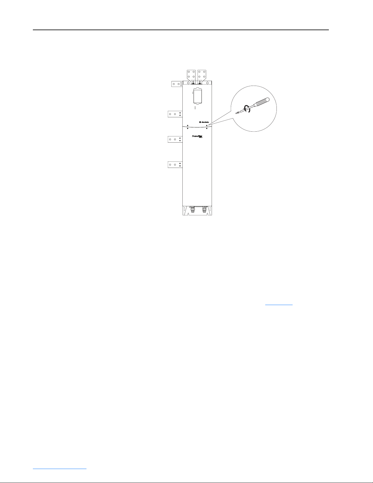
Removing the Active Converter Power Module Covers
All converter covers, regardless of drive frame size, are similarly removed
by unfastening the screws. A Frame 3B converter is shown as an example.
PORT
MOD
NET A
NET B
(4 Screws)
PowerFlex 700L
Liquid-Cooled AC Drive
Frame 3B Converter shown
Removing the Active Converter Control Cassette
Regenerative PowerFlex 700L Liquid-Cooled AC drives use an Active
Converter Power Module equipped with a converter control cassette.
Frame 2 and 3A Drives
PowerFlex 700L Liquid-Cooled Frame 2 and 3A drives combine the Active
Converter and Inverter into a single Power Module. Figure 1.1
location and removal of the Active Converter control cassette to access its
terminal blocks for control wiring. (The Inverter control cassette is located
just above the Active Converter control cassette.)
shows the
PowerFlex 700L Active Converter Power Module User Manual
Publication PFLEX-UM002D-EN-P
Page 13
Installation/Wiring 1-3
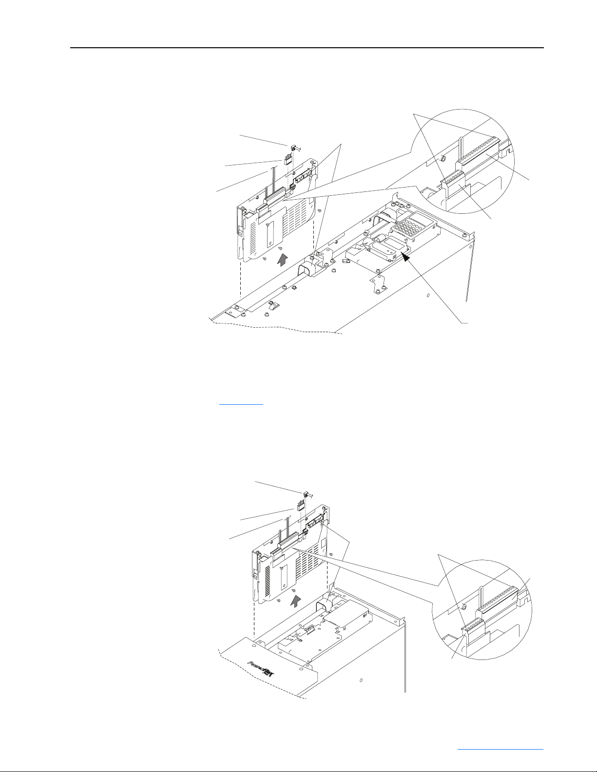
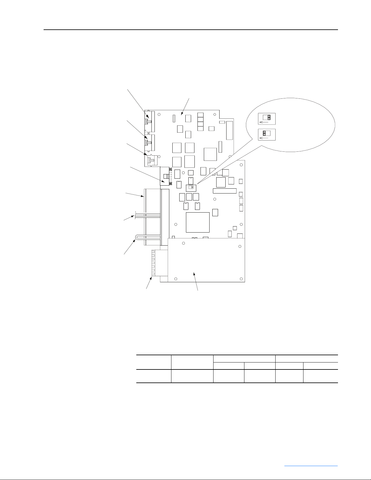
Figure 1.1 Removing the Frame 2 and 3A Active Converter Control Cassette
Synchronization Cable
(For use with 700S Phase II Control only)
Internal DPI Cable
Synchronization Cable
(For use with 700 Vector Control only)
Frame 3B Drives
Pin 1
40-Pin
Ribbon Cable
SHLD
SHLD
Communications
Adapter Option
Detail
P1
P2
Figure 1.2 shows the location and removal of the Active Converter control
cassette to access its terminal blocks for control wiring. Frame 3B drives
have separate Converter Power Modules and Inverter Power Modules.
Figure 1.2 Removing the Frame 3B Active Converter Control Cassette
Synchronization Cable
(For use with coupled Inverter Power
Modules with 700S Phase II Control only)
Internal DPI Cable
Synchronization Cable
(For use with coupled Inverter Power
Modules with 700 Vector Control only)
40-Pin
Ribbon Cable
Pin 1
P2
P1
Detail
PowerFlex 700L Active Converter Power Module User Manual
Publication PFLEX-UM002D-EN-P
Page 14

1-4 Installation/Wiring
Wiring the Active Converter Control Cassette I/O Terminals
All wiring should be installed in conformance with the applicable local,
national, and international codes (e.g., NEC/CEC). Signal wiring, control
wiring, and power wiring must be routed in separate conduits to prevent
interference with drive operation. Use grommets, when hubs are not
provided, to guard against wire chafing.
ATTENTION: Do not route signal and control wiring with
!
Important points to remember about I/O wiring:
• Use Copper wire only. Wire gauge requirements and recommendations
are based on 75 degrees C. Do not reduce wire gauge when using higher
temperature wire.
• Wire with an insulation rating of 600V or greater is recommended.
• Control and signal wires should be separated from power wires by at
least 0.3 meters (1 foot).
Important:I/O terminals labeled “(–)” or “Common” are
power wiring in the same conduit. This can cause interference
with drive operation. Failure to observe this precaution could
result in damage to, or destruction of, the equipment.
not referenced to
earth ground and are designed to greatly reduce common mode
interference. Grounding these terminals can cause signal noise.
Terminal blocks P1 and P2, shown in Figure 1.1
connection points for all inputs, outputs, and power connections to the
Active Converter control cassette.
1. Remove the terminal block plug from the socket, and make connections.
2. Reinstall the terminal block plug when wiring is complete. The terminal
blocks have keys, which make it difficult to insert a terminal block plug
into the wrong socket.
and Figure 1.3, contain
PowerFlex 700L Active Converter Power Module User Manual
Publication PFLEX-UM002D-EN-P
Page 15
J1 40-Pin
Ribbon Cable
Header
Installation/Wiring 1-5
Figure 1.3 Active Converter Control Cassette I/O Terminal, Cable Connection, and
DPI SLAVE/MASTER Switch SW1 Locations
Active Converter
Control PCB Assembly
J2 30-Pin
Ribbon Cable
Header
J9 Synchronization
Cable Header
(700S Ph. II Control only)
J4 Internal DPI
Cable Header
P1 I/O Terminals
(see Table 1.B for
terminal descriptions)
P1-7 and P1-8
Synchronization
Cable Connection
(700 Vector Control only)
P1-13 and P1-14
Factory-Installed
Gate Kill Jumper
SW1
DPI SLAVE = OFF
ON
DPI MASTER = ON
ON
1
2
3
4
5
6
7
8
9
10
11
12
13
14
15
7
6
5
4
3
2
1
SW1
P2 I/O Terminals
(see Table 1.C for
terminal descriptions)
I/O Terminal Blocks
Table 1.A Active Converter Control Board I/O Terminal Block Specifications
Name Description
I/O Blocks Signal and power
(1)
Voltage Feedback
Resistor PCB Assembly
Wire Size Range
Maximum Minimum Maximum Recommended
2
connections
Maximum/minimum that the terminal block will accept - these are not recommendations.
1.5 mm
(16 AWG)
(1)
2
0.14 mm
(28 AWG)
PowerFlex 700L Active Converter Power Module User Manual
0.25 N-m
(2.2 lb.-in.)
Publication PFLEX-UM002D-EN-P
Torque
0.22 N-m
(1.9 lb.-in.)
Page 16

1-6 Installation/Wiring
Table 1.B Active Converter Control PCB Assembly P1 Terminal Descriptions
Pin Description
1Comm Out +
2Comm Out 3 SOC Out +
4 SOC Out 5 Comm In +
6 Comm In 7 SOC In +
8 SOC In 9Aux Out N.O.
10 Aux Out Common
11 Analog In Signal
12 Analog In Common
13 Gate Enable
14 24 Vdc
15 Aux Input
Table 1.C Voltage Feedback Resistor PCB Assembly P2 Terminal Descriptions
Pin Description
7L3
4L2
1L1
Specific pins on P1 and P2 terminals require control wiring connections to
the Input Filter Bay. For wiring information, please refer to the PowerF lex
700L Liquid-Cooled Adjustable Frequency AC Drive User Manual
(Publication No. 20L-UM001…).
Using the Active Converter as a Coupled Unit vs. Standalone Unit
Frame 3B converter power structures may be ordered as a unit Coupled to
an inverter (DPI SLAVE), or as a Stand Alone unit (DPI MASTER). Frame
2 and Frame 3A power structures are always wired for the converter to be a
Coupled unit.
Coupled
Figure 1.4
(DPI SLAVE). In this configuration, the Converter is connected to a
PowerFlex 700L Inverter through DPI Port 6. When configured for "Run On
Start," the Converter is able to start and stop automatically as the Inverter is
started and stopped.
shows the Active Converter wired to operate as a Coupled unit
PowerFlex 700L Active Converter Power Module User Manual
Publication PFLEX-UM002D-EN-P
Page 17
Installation/Wiring 1-7
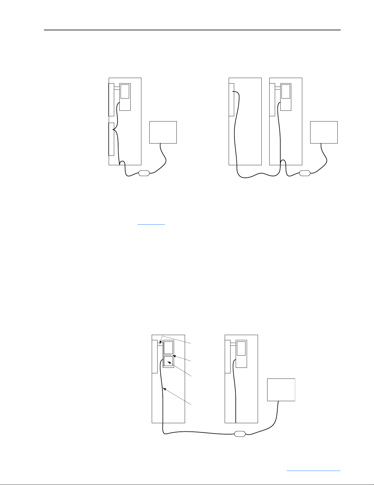
Figure 1.4 Active Converter Operating as a Coupled Unit (DPI SLAVE)
Frame 3A with Converter as a
Coupled Unit (DPI SLAVE)
I
n
HIM HIM
v
e
r
t
e
r
C
o
n
v
e
r
t
e
r
1203-USB or 1203-SSS
Serial Converter
Personal
Computer
Stand Alone
Figure 1.5
unit (DPI MASTER). In this configuration, the Converter may have a HIM
or any PowerFlex 7-Class network communication adapter (20-COMM-x)
connected. This may be preferred when the converter is to supply the DC
bus for a set of common bus inverters. When configured for "Run On Start,"
the precharge bypass contactor may be configured to close when the power
is turned on and the DC Bus voltage is stable (see Parameter 51 - [Option
Select]). The Converter starts and stops with commands from the HIM, the
1203-USB or 1203-SSS serial converter, or a 20-COMM-x network
communication adapter.
Frame 3B with Converter as a
Coupled Unit (DPI SLAVE)
C
o
n
v
e
r
t
e
r
I
n
v
e
r
t
e
r
1203-USB or 1203-SSS
Serial Converter
Personal
Computer
shows the Active Converter wired to operate as a Stand Alone
Figure 1.5 Active Converter Operating as a Stand Alone Unit (DPI MASTER)
Frame 3B with Converter as a
Stand Alone Unit (DPI MASTER)
C
o
HIM
n
v
e
r
t
e
r
196755-C01
193136
20-COMM-x
181046-C01
I
n
HIM
v
e
r
t
e
r
1203-USB or 1203-SSS
Serial Converter
PowerFlex 700L Active Converter Power Module User Manual
Personal
Computer
Publication PFLEX-UM002D-EN-P
Page 18

1-8 Installation/Wiring
The Frame 3B Active Converter power module is ordered as a Stand Alone
unit (DPI SLAVE) by specifying equipment type P in the catalog number
(refer to the catalog number explanation in the PowerFlex 700L User
Manual).
The Stand Alone (DPI SLAVE) Active Converter is supported with Active
Converter firmware revision 3.001 (or higher).
To operate the Frame 3B Active Converter as a Stand Alone unit (DPI
SLAVE) the DPI MASTER/SLAVE switch (SW1) on the Active Converter
control board must be properly set. Refer to Setting the DPI MASTER/
SLAVE Switch (SW1) below for details.
Setting the DPI MASTER/SLAVE Switch (SW1)
Active Converters with version 2.006 (or lower) firmware are always
operated as a peripheral on DPI port 6. In this case, switch SW1 on the
Active Converter control PCB assembly (Figure 1.3
SLAVE). Do not use the ON setting. For Active Converters with version
3.001 (or higher) firmware, switch SW1 is used to select between converter
operation as a Coupled unit (DPI SLAVE position) or as a Stand Alone unit
(DPI MASTER position).
) is set to OFF (DPI
Connecting an Active Converter Power Module to an Inverter Power Module
Frame 2 and 3A Drives
Coupling a Frame 2 or 3A Power Module is achieved by using two cables: a
DPI cable and a control synchronization cable. These cables are factory
installed.
Frame 3B Drives
Coupling a Frame 3B Active Converter Power Module to a Frame 3B
Inverter Power Module is achieved by using two cables: a DPI cable and a
control synchronization cable. For the Complete Drive equipment type,
these cables are factory installed. When Power Modules are purchased
separately, these cables are user installed. For information regarding these
cables and their installation, please refer to the PowerFlex 700L
Liquid-Cooled Adjustable Frequency AC Drive User Manual (Publication
No. 20L-UM001…), Chapter 3 in the “Synchronization Connections for
Frame B” section.
PowerFlex 700L Active Converter Power Module User Manual
Publication PFLEX-UM002D-EN-P
Page 19
Chapter 2
Start Up
The start-up procedure built into the HIM addresses only the start up of the
inverter. This chapter describes how to start up the PowerFlex 700 Active
Converter Power Module.
For information on… See page…
Establishing Communication as a Coupled Unit
Establishing Communication as a Stand Alone Unit 2-8
Converter Sequencing 2-12
Control Setup 2-14
Converter Faults 2-17
2-1
Establishing Communication as a Coupled Unit
When the Converter is set to operate as a Coupled unit (DPI SLAVE), the
first step after turning on power is to verify that you are able to
communicate with the unit and that it properly displays selected data.
Data is exchanged between the Inverter Power Module and Active
Converter Power Module to pass control and status information.
An example is given for how to communicate with the Active Converter
Power Module using a CIP message from a ControlLogix controller.
Accessing Active Converter Power Module Parameters
The Active Converter operates as a DPI peripheral on port 6. This section
describes how to access parameters in the Active Converter.
Using the HIM
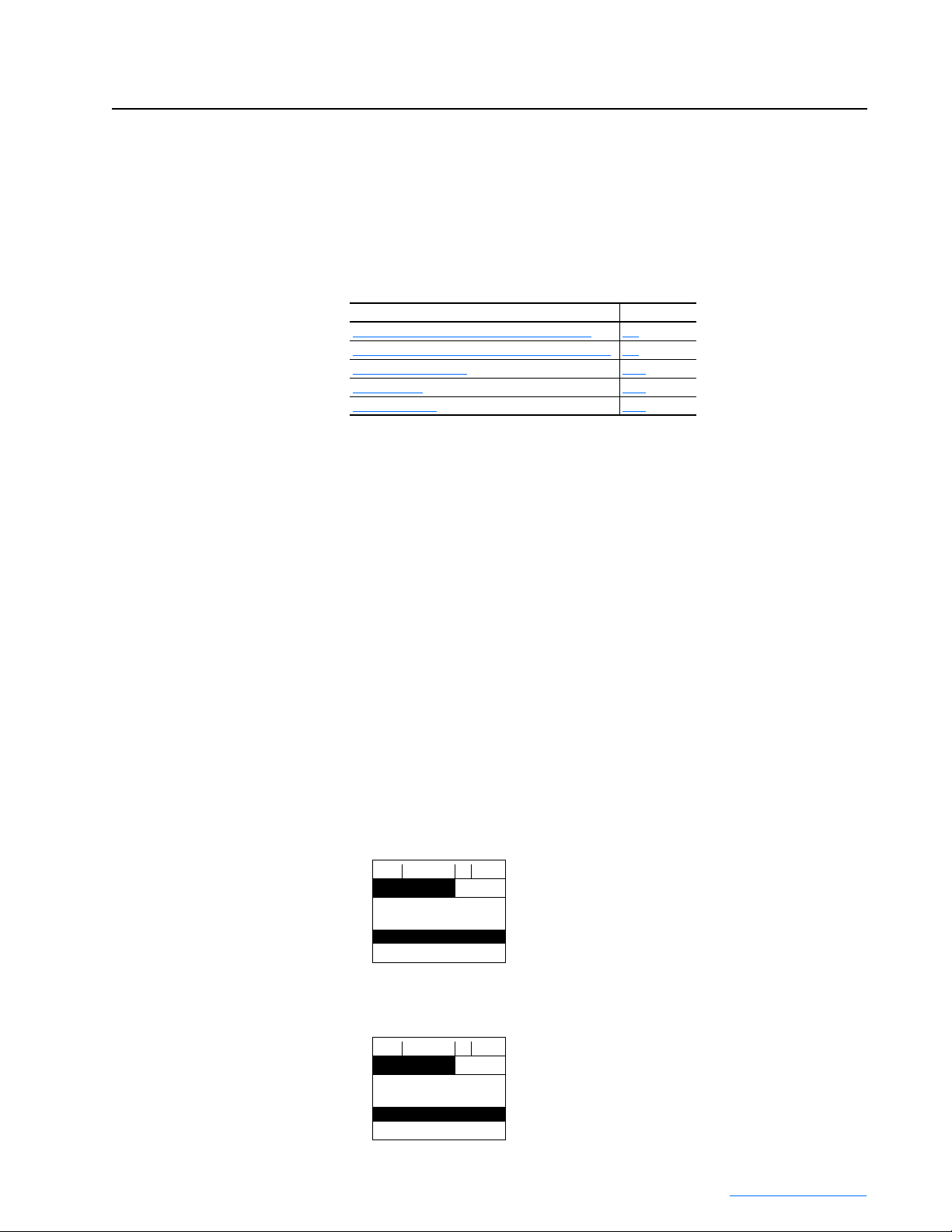
1. On power up, the HIM displays the main menu and communicates with
the Inverter.
F-> Stopped Auto
0.0 RPM
Main Menu:
Diagnostics
Parameter
Device Select
2. As you scroll down to “Device Select,” the HIM shows the following
indication. With “Device Select” highlighted, press the Enter key.
F-> Stopped Auto
0.0 RPM
Main Menu:
Parameter
Device Select
Memory Storage
PowerFlex 700L Active Converter Power Module User Manual
Publication PFLEX-UM002D-EN-P
Page 20
2-2 Start Up
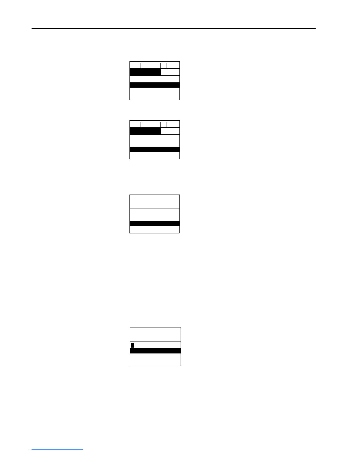
3. The HIM displays that it is currently communicating with the Inverter on
DPI Port 0.
F-> Stopped Auto
0.0 RPM
Device: Port 0
PowerFlex 700S 2
PowerFlex 700 AC
4. Press the Down arrow to scroll to “PowerFlex 700 AC.”
F-> Stopped Auto
0.0 RPM
Device: Port 6
PowerFlex 700S 2
PowerFlex 700 AC
5. With “PowerFlex 700 AC” highlighted as shown in Step 4, press the
Enter key to start communicating with the Active Converter on DPI Port
6.
Port 6 Device
PowerFlex 700AC
Main Menu:
Diagnostics
Parameter
Device Select
– To examine the fault queue in the Active Converter, press the Up
Arrow to scroll to “Diagnostics” and press the Enter key.
– To begin examining parameters (with “Parameters” highlighted),
press the Enter key.
– To resume communication with the Inverter, press the Down Arrow to
scroll to “Device Select” and press the Enter key.
6. After accessing the Parameter menu, the display shows the File menu.
Press the Up or Down Arrow to select the desired file and press the Enter
key.
Port 6 Device
PowerFlex 700AC
FGP: File
Monitor
Command
Limit Config
PowerFlex 700L Active Converter Power Module User Manual
Publication PFLEX-UM002D-EN-P
Page 21
Start Up 2-3
7. The display then shows the groups of parameters in the selected file.
Press the Up or Down Arrow to select the desired group and press the
Enter key.
Port 6 Device
PowerFlex 700AC
FGP: Group
Current
Vol ta ge
Power & Ti me
8. The display then shows the parameters in the selected group. Press the
Up or Down Arrow to select the desired parameter and press the Enter
key.
Port 6 Device
PowerFlex 700AC
FGP: Parameter
Rated Amps
Input Current R
Input Current S
9. The display then shows the value of the selected parameter and allows
for entry of a new value for parameters that are read/write.
Port 6 Device
PowerFlex 700AC
FGP: Par 1
Rated Amps
705.0 Amps
[Alt] [View] - > Limits
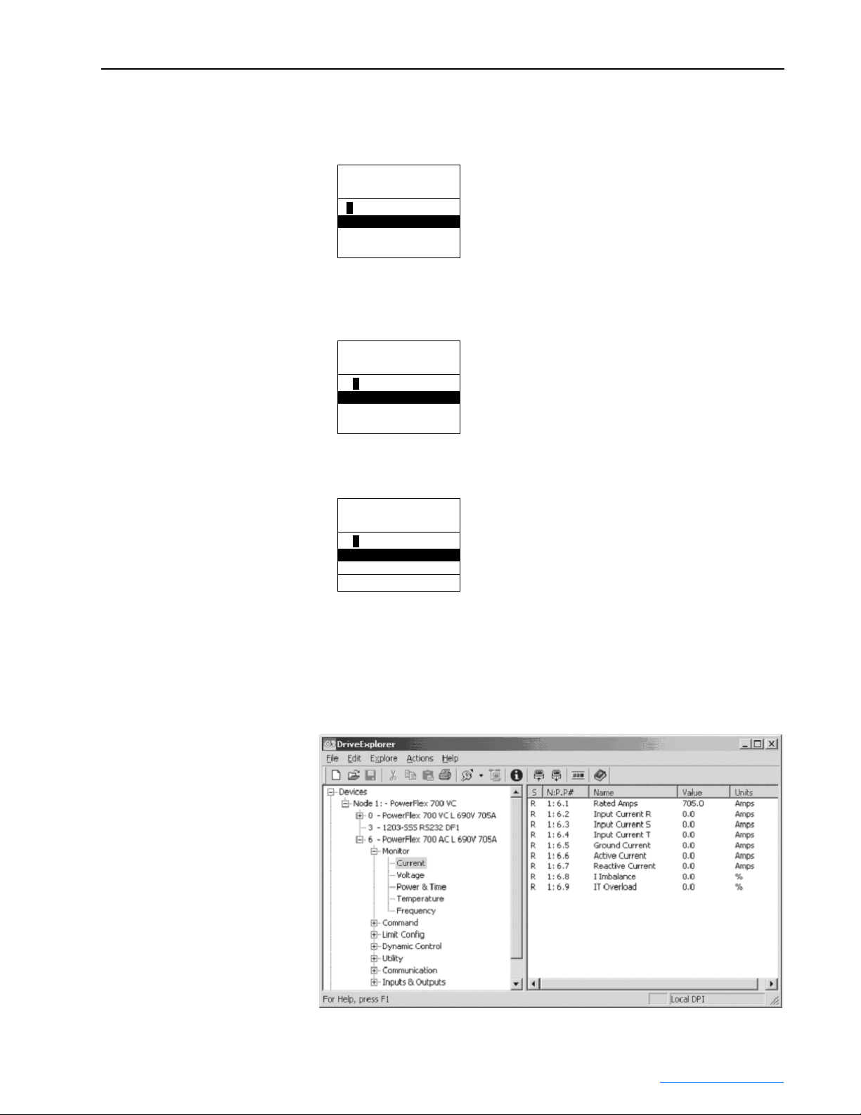
Using DriveExplorer
When using DriveExplorer, the window shows the files and groups for the
Active Converter (left pane) and the parameters for the selected group (right
pane). Double-click a parameter in the right pane to edit it
PowerFlex 700L Active Converter Power Module User Manual
Publication PFLEX-UM002D-EN-P
Page 22
2-4 Start Up
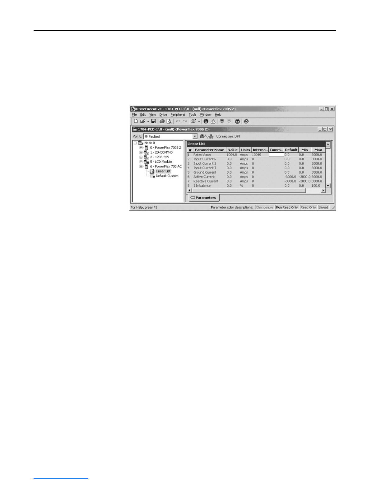
Using DriveExecutive
When using DriveExecutive, the Active Converter parameters are displayed
in a linear list. Uploading reads parameter values from all DPI peripherals
but downloading parameters only write to the Inverter. To download
parameter values to the Active Converter, you must first select the
Converter.
Verifying Feedback Parameters
Using the HIM, DriveExplorer or DriveExecutive, verify that reasonable
values are displayed for the following parameters in the Active Converter
Power Module:
• Line to Line Voltage – Verify converter parameters 11 - [Input Voltage
RS], 12 - [Input Voltage ST], and 13 - [Input Voltage TR] display a
reasonable Line to Line RMS Voltage. Verify the voltage imbalance
displayed in parameter 16 - [V Imbalance] does not exceed 5.0%.
• DC Link Voltage – Verify converter parameter 14 - [DcLink Voltage]
displays a reasonable DC Link Voltage.
• AC Line Frequency – Verify converter parameter 40 - [Line Frequency]
displays a reasonable AC Line Frequency.
• Ambient Temperatures – Verify converter parameter 30 - [Ambient
Temp] displays a reasonable ambient temperature. Verify parameter 32 [IGBT Junction Temp] displays the temperature of the liquid being
pumped through the coldplate.
PowerFlex 700L Active Converter Power Module User Manual
Publication PFLEX-UM002D-EN-P
Page 23

Start Up 2-5
Exchanging Data
DPI Type 3 communication is used to exchange control and status
information between the Inverter and the Converter. This provides a
mechanism to start and stop the Converter as the Inverter is started and
stopped. It also transfers the minimum DC Link voltage required for the
given motor voltage to the Converter, and any Converter fault codes back to
the Inverter so all faults are maintained in the Inverter’s fault queue. The
data exchanged is displayed in these Active Converter parameters:
• 70 - [Converter Control] • 72 - [Converter Min Vdc]
• 71 - [Converter Status] • 73 - [Converter Fault]
No setup is required to configure the Type 3 communication. The Converter
requests a Type 3 connection at power up and, when the connection is
complete, Converter parameter 320 - [Connect Status] shows which
communication types are active. The use of Type 3 communication for
exchange of data is important in that none of the normal data links are used
for this communication. By default, all four sets of DPI data links remain
available for use in a 20-COMM-* adapter.
The automatic starting and stopping of the Active Converter requires the
Converter to be configured for “0 = Run On Start” using Converter
parameter 50 - [Start Config]. In this case, when the Inverter is started or
jogged, the Converter is enabled and the Inverter sequencing delays running
the Inverter for up to 500 milliseconds, allowing the Converter to close the
precharge bypass contactor. When the Inverter is stopped, the Converter
continues to run for the time configured in Converter parameter 53- [Turn
Off Delay]. On a subsequent start or jog, the Inverter does not need to wait
for the precharge to close if the Converter is still running.
Start Jog
Inverter
Functions
Inverter
Communications
Converter
Communications
PF700 AC
Parameters
AC 70 - [Converter Control]
AC 72 - [Converter Min Vdc]
Inverter Sequencing
Inverter DPI Type 3
Producer / Consumer
Converter DPI Type 3
Producer / Consumer
AC 71 - [Converter Status]
AC 73 - [Converter Fault]
Converter
Functions
Converter Sequencing
Precharge
Contactor
PowerFlex 700L Active Converter Power Module User Manual
Converter
Enable
Publication PFLEX-UM002D-EN-P
Page 24

2-6 Start Up
In addition to Type 3 communication, the 700S may optionally use DPI data
links to control the sequencing of the Converter from a Logix processor as
shown below. This requires the Converter to be configured for Manual
Control in Converter parameter 50 - [Start Config]. The reference for the
voltage loop may also be controlled by a Logix processor when Converter
parameter 160 - [Voltage Loop Sel] is set to Manual Ref.
The DPI data links between the Inverter and Converter are enabled by
setting Converter parameters 300 - [Data In A1] through 317 - [Data Out
D2] to the parameter number of the data to send or receive. When a DPI
data link is used by the Converter, that channel cannot be used by a different
communication card. The following example illustrates using DPI data links
between the Inverter and Converter.
Suppose Inverter parameter 666 is linked to Converter parameter 52 [Manual Control], Inverter parameter 667 is linked to Converter parameter
60 - [DcLink Reference], and Converter parameter 71 - [Converter Status] is
linked to Inverter parameter 657. This requires Converter data links to be
configured as follows:
• Active Converter parameter 306 [Data In D1] = 52
• Active Converter parameter 307 [Data In D2] = 60
• Active Converter parameter 316 [Data Out D1] = 71
This example shows Data Link D being used to communicate with the
Converter. The Converter supports DPI Data Links A, B, C, and D so any
group could be used as needed.
All the options for starting and stopping the Converter are explained in
greater detail in Converter Sequencing
Logix
PF700 S
Parameters
Inverter
Communications
Converter
Communications
PF700 AC
Parameters
S 667 - [DPI Data Out D2]
AC 52 - [Manual Control]
AC 60 - [DcLink Reference]
on page 2-12.
S 657 - [DPI Data In D1]S 666 - [DPI Data Out D1]
Inverter DPI Data Link
Producer / Consumer
Converter DPI Data Link
Producer / Consumer
AC 71 - [Converter Status]
PowerFlex 700L Active Converter Power Module User Manual
Publication PFLEX-UM002D-EN-P
Converter
Functions
Converter Sequencing
Precharge
Contactor
Converter
Enable
Page 25

Start Up 2-7
CIP Messages
Parameters in the Converter may be accessed by a Logix processor using a
CIP message block. To read or write a parameter value you must
respectively perform a Get Attribute Single or Set Attribute Single message
to the DPI Parameter Object (Class 0x93). The Converter is in DPI Port 6,
so the instance is 22528 plus the parameter number. The value of the
parameter is accessed through Attribute 0x9 or 0xA. The example shown
below reads the value of Converter parameter 30 - [Ambient Temp].
Class Code
Hexadecimal Decimal
0x93 147
Instances
Instances (Hex.) (Dec.) Device
0x0000 – 0x3FFF 0 – 16383 Host
0x4000 – 0x43FF 16384 – 17407 Adapter
0x4400 – 0x47FF 17408 – 18431 DPI Port 1
0x4800 – 0x4BFF 18432 – 19455 DPI Port 2
0x4C00 – 0x4FFF 19456 – 20479 DPI Port 3
0x5000 – 0x53FF 20480 – 21503 DPI Port 4
0x5400 – 0x57FF 21504 – 22527 DPI Port 5
0x5800 – 0x5BFF 22528 – 23551 DPI Port 6
Attributes
ID Rule Name Data Type Description
0x9 Get/Set Parameter Value Various Value in NVS
0xA Get/Set Parameter Value Various Value in RAM
PowerFlex 700L Active Converter Power Module User Manual
Publication PFLEX-UM002D-EN-P
Page 26

2-8 Start Up
Establishing Communication as a Stand Alone Unit
When the Converter is set to operate as a Stand Alone unit (DPI MASTER),
the first step after turning on power is to verify that you are able to
communicate with the unit and that it properly displays selected data.
Accessing Active Converter Power Module Parameters
Using the HIM
1. On power up, the HIM displays the AC Line Frequency, the Active
Current, and the DC Bus Voltage. The status text will display one of five
indications: Faulted, Start Inhibit, Ready, Running or Ride Through.
F-> Ready Auto
59.97 Hz
0.00 Amps
664.20 Bus VDC
2. Access the parameters of the Converter by selecting Parameter on the
Main Menu.
F-> Ready Auto
59.97 Hz
Main Menu:
Diagnostics
Parameter
Device Select
3. Parameters may then be accessed with the File, Group, Parameter menu,
F-> Ready Auto
59.97 Hz
FGP: File
Monitor
Command
Limit Config
or with a Numbered List.
F-> Ready Auto
59.97 Hz
Parameter : #
Rated Amps
650.0 Amps
[Alt] [View] - > Limits
The start and stop buttons may start and stop the Converter. The stop button
may also be used to reset a fault in the Converter. The speed, jog, forward/
reverse, and auto/manual buttons are not functional.
F-> Ready Auto
FGP: File
Current
Voltage
Power & Time
1
59.97 Hz
F-> Ready Auto
59.97 Hz
FGP: File
Rated Amps
Input Current R
Input Current S
PowerFlex 700L Active Converter Power Module User Manual
Publication PFLEX-UM002D-EN-P
Page 27

Start Up 2-9
Using DriveExplorer or DriveExecutive
When using DriveExplorer or DriveExecutive, the Converter parameters are
displayed under Port 0 and are organized into the normal menu of Files,
Groups, and Parameters. The control bar can be opened to show a stop and
start push button.
Verifying Feedback Parameters
Using the HIM, DriveExplorer or DriveExecutive, verify that reasonable
values are displayed for the following parameters in the Active Converter
Power Module:
• Line to Line Voltage – Verify converter parameters 11 - [Input Voltage
RS], 12 - [Input Voltage ST], and 13 - [Input Voltage TR] display a
reasonable Line to Line RMS Voltage. Verify the voltage imbalance
displayed in parameter 16 - [V Imbalance] does not exceed 5.0%.
• DC Link Voltage – Verify converter parameter 14 - [DcLink Voltage]
displays a reasonable DC Link Voltage.
• AC Line Frequency – Verify converter parameter 40 - [Line Frequency]
displays a reasonable AC Line Frequency.
• Ambient Temperatures – Verify converter parameter 30 - [Ambient
Temp] displays a reasonable ambient temperature. Verify parameter 32 [IGBT Junction Temp] displays the temperature of the liquid being
pumped through the coldplate.
PowerFlex 700L Active Converter Power Module User Manual
Publication PFLEX-UM002D-EN-P
Page 28

2-10 Start Up
Using a 20-COMM-x Adapter
When a 20-COMM-x network communication adapter is connected to the
Converter, the Product Logic Command bits may be used to start and stop
the Converter and to reset a fault. All other bits are reserved. The Product
Logic Status bits may be used to determine the state of the Converter.
Converter Logic Command Word
Logic Bits
1514131211109876543210Command Description
x Stop 0 = Not Stop
x Start 0 = Not Start
x Reserved
x Fault Reset 0 = Not Fault Reset
x Reserved
x Reserved
x Reserved
x Reserved
x Reserved
x Reserved
x Reserved
x Reserved
x Reserved
x Reserved
x Reserved
x Reserved
1 = Stop
1 = Start
1 = Fault Reset
Converter Logic Status Word
Logic Bits
15 14 13 12 11 10 9 8 7 6 5 4 3 2 1 0 Status Description
x Ready 0 = Not Ready
x Running 0 = Not Running
x Reserved
x Reserved
x Reserved
x Reserved
x Reserved
x Reserved
x Reserved
x Reserved
x Reserved
x Reserved
x Reserved
x Reserved
The reference value from the 20-COMM-x adapter that is often used to
select the speed is not used in the Converter. The Converter is always
xAlarm0 = No Alarm
x Fault 0 = No Fault
1 = Ready
1 = Running
1 = Alarm
1 = Fault
PowerFlex 700L Active Converter Power Module User Manual
Publication PFLEX-UM002D-EN-P
Page 29

Start Up 2-11
synchronized to the AC line frequency and does not have a speed reference.
The feedback value sent to the 20-COMM-x adapter is the measured AC
line frequency, where a value of 32767 corresponds to 100.00 Hz.
The Converter supports 16-bit data links so if all data links are configured in
the 20-COMM-x then the Connection Parameters in the Logix Processor
must be setup as shown here. This defines twelve 16-bit words sent from the
20-COMM-x to the Logix, and ten 16-bits words sent from the Logix to the
20-COMM-x.
The data is utilized as shown below:
Logix to 20-COMM-x 20-COMM-x to Logix
Word Output I/O Word Input I/O
1 Logic Command 1 Not Used
2 Reference (not used) 2 Not Used
3 Datalink In A1 3 Logic Status
4 Datalink In A2 4 Feedback (AC line frequency)
5 Datalink In B1 5 Datalink Out A1
6 Datalink In B2 6 Datalink Out A2
7 Datalink In C1 7 Datalink Out B1
8 Datalink In C2 8 Datalink Out B2
9 Datalink In D1 9 Datalink Out C1
10 Datalink In D2 10 Datalink Out C2
11 Datalink Out D1
12 Datalink Out D2
PowerFlex 700L Active Converter Power Module User Manual
Publication PFLEX-UM002D-EN-P
Page 30

2-12 Start Up
Converter Sequencing
The condition when to start and stop the Converter must be configured in
parameter 50 - [Start Config]. There are three ways to operate the
Converter: Run On Start, Run On Power Up, and Manual Control. This also
configures how the precharge bypass contactor operates.
Run On Start
When Converter parameter 50 - [Start Config] is set to “0 = Run On Start,”
the operation changes when the Converter is set as a Coupled unit (DPI
SLAVE) or a Stand Alone unit (DPI MASTER) using SW1 (Figure 1.3
Coupled Unit (DPI SLAVE Setting)
When set as a Coupled unit (DPI SLAVE) and Run on Start is selected, then
starting and stopping the Converter is coordinated with starting and
stopping the Inverter. When the Inverter is started or jogged, the Converter
is enabled to turn on. When the Inverter is stopped or jog is released, the
Converter is stopped.
Stand Alone Unit (DPI MASTER Setting)
When set as a Stand Alone unit (DPI MASTER) and Run on Start is
selected, then the Converter may be started and stopped from the buttons on
a HIM, or by the Logic Command bits transmitted by a 20-COMM-x
adapter or 1203-USB or 1203-SSS device. The logic masks determine
which DPI ports are allowed to take control.
).
Precharge Bypass Operation
In Run On Start, the precharge can be configured to operate in one of two
ways as selected by parameter 51 - [Option Select], Bit 7 (Precharge
Control). By default, this option bit is turned off so the precharge bypass
contactor will be commanded to close at the time the Converter is
commanded to start, and the bypass contactor opens after the Converter is
commanded to stop. If the option bit is set, then the bypass contactor is
closed at power up after the DC bus is at steady state.
If there is a fault in the Converter, the precharge bypass contactor will open.
If the option bit is set, the bypass contactor is closed when the fault is reset.
The option bit also selects how long the Converter continues to run after it is
commanded to stop. If the option bit is turned off, then parameter 53 - [Turn
Off Delay] selects the time delay between the stop command and the time
when the converter is stopped and the bypass is opened. If the option bit is
turned on, then the Converter stops without a delay.
As a Coupled unit (DPI SLAVE), Run On Start with the precharge option
bit turned off is recommended for applications where the drive is left
powered up but the drive is not run for extended periods of time. With the
precharge bypass contactor open, the fan cooling the input reactor is turned
off.
PowerFlex 700L Active Converter Power Module User Manual
Publication PFLEX-UM002D-EN-P
Page 31

Start Up 2-13
Run On PwrUp
When Converter parameter 50 - [Start Config] is set to “1 = Run On
PwrUp,” the precharge bypass contactor is automatically closed and the
Converter is enabled shortly after power is turned on.
The precharge will close as soon as the DC Link voltage is above the
minimum required level and it has reached steady state. The precharge will
remain closed when there is a fault in the Converter. When the fault is reset,
the Converter will go back into run. In this configuration, the coolant
circulating loop must be enabled when the Converter is enabled, even if the
Inverter is not in run. The auxiliary contacts on the precharge bypass could
be used to enable the circulating pump.
This mode of operation is recommended for applications where the drive is
powered down when it is to be stopped for an extended period of time.
Manual Cntrl
When Converter parameter 50 - [Start Config] is set to “2 = Manual Cntrl,”
the operation of the precharge bypass contactor and enabling of the
Converter is controlled by two bits in Converter parameter 52 - [Manual
Control]. The bits are normally level sensitive. Turning the bits on closes the
bypass contactor and enables the Converter. Turning the bits off opens the
bypass contactor and disables the Converter.
The exception is that if there is a fault, the bypass contactor is not allowed to
close. After a fault, the fault must be reset, and then a rising edge on bit 1 in
parameter 52 - [Manual Control] is required to re-enable the Converter. The
value in parameter 52 is not retentive; it is reset to zero on power up.
When operating as a Coupled unit (DPI SLAVE), the Inverter is not allowed
to start with the precharge open and the Inverter will fault if it started with
the Converter stopped. When operating as a Stand Alone unit (DPI
MASTER), the value in parameter 52 - [Manual Control] may be written by
a datalink and the value in parameter 72 - [Converter Status] may be read
with a datalink and used as part of the interlocks with Inverters.
Start Inhibit
If the Converter does not start when expected, refer to Converter parameter
214 - [Start Inhibit] to display the Start Inhibit conditions.
Sequencing Precautions
When operating as a Coupled unit (DPI SLAVE) that is supplying power to
a single Inverter, the built-in interlocks will not allow the Inverter to start
unless the Converter is running, and the Converter will not stop when the
Inverter is running. However, when the Converter is operated as a Stand
PowerFlex 700L Active Converter Power Module User Manual
Publication PFLEX-UM002D-EN-P
Page 32

2-14 Start Up
Alone unit (DPI MASTER) and is supplying power to a common bus, extra
precaution must be taken.
ATTENTION: When operating as a Stand Alone unit (DPI
MASTER) or supplying power to a common bus, external logic
!
must be used to make sure the precharge bypass contactor is
closed and the Converter is running before running an Inverter.
Likewise, all Inverters must stop if the precharge opens or the
Converter stops.
Operating an Inverter with the precharge bypass open will overheat the
precharge resisters. Operating an Inverter with the Converter stopped will
draw non-sinusoidal current with peak current greater than rated and will
have significant harmonic distortion.
Control Setup
The following topics discuss parameters that should be reviewed when
starting up an Active Converter.
Current Limits
Converter parameter 100 - [Active I Lmt] defines the limit on active current.
This parameter defaults to 150% of Converter rated current. Current limit
for regeneration is set in parameter 105 - [Regen I Lmt]. This defaults to
-150% of Converter rated current. When in current limit, the Converter is
unable to regulate the DC link voltage. If the drive is motoring and the
Converter is in current limit, then the DC link will drop to the peak of the
AC line. If the drive is regenerating and the Converter is in current limit, the
DC link will rise and it is up to the Inverter to limit its regenerating current
to avoid a high bus fault.
The Converter parameter 71 - [Converter Status] word bit 4 (Bus Reg Ena)
turns on when the Converter is in current limit to command the Inverter to
enable its bus voltage regulators. When the Converter is active and Bus Reg
Ena is turned off, the bus voltage regulators in the Inverter are turned off.
Line Voltage Limits
PowerFlex 700L Active Converter Power Module User Manual
Publication PFLEX-UM002D-EN-P
The limits on line voltage may need to be adjusted to indicate abnormal
conditions. At low line voltages, the Converter will deliver greater amps to
produce the same power. If the possible range of input voltage would result
in a condition that would exceed the rated current, then the voltage limits
must be set to guard against this condition. The low voltage and high
voltage limits have timers associated with each limit to allow brief
excursions outside of normal operating conditions. See Converter
parameters 112 -[Low Vac Lmt] through 115 - [High Vac Time].
Page 33

Start Up 2-15
Frequency Limits
The PWM Carrier Frequency is fixed at 4 kHz and cannot be changed.
If operating on a generator, the normal range of acceptable AC line
frequencies may need to be expanded. The limit of the rate of change may
also need to be adjusted to allow the line synchronization to properly track
the changes in frequency. See Converter parameters 131 - [AC Low Freq
Lmt] through 135 - [AC Maximum dF/dt].
Voltage Loop
The voltage major loop uses Vdc Reference and Vdc Feedback to calculate
the required active current to maintain a constant DC bus voltage.
Voltage Reference Selection
Converter parameter 160 - [Voltage Loop Sel] selects the value used for the
DC Link voltage reference. One of two values may be chosen at this time;
“0 = Optimized Ref” and “1 = Manual Ref.” The Regen Only option is
reserved for future enhancements, and the Open Loop option is reserved for
manufacturing tests. A password must be entered to use the Open Loop
option.
When “0 = Optimize Ref” is selected, the value for the DC Link reference is
calculated as the minimum value for the given operating condition to reduce
switching losses and increase efficiency. The base value for DC Link
reference is 1.44 times the RMS AC line. For a 480 volt line, the DC link
reference starts at 692 Vdc. This is 2% above the peak of the AC line. In
applications where the maximum motor voltage is greater than the AC line,
the Converter can boost the DC link to a higher level. The Inverter
calculates the minimum required DC link for the present motor voltage and
transmits that value to Converter parameter 72 - [Converter Min Vdc]. As
the line voltage goes up and down and as the Inverter’s motor voltage goes
up and down, the DC Link reference goes up and down to match the
operating conditions.
This option is most useful when there are significant changes in the line
voltage. This option is not recommended for common bus applications
where multiple Inverters operate at different speeds.
When “1 = Manual Ref” is selected, the value for DC Link reference is the
value in parameter 60 - [DcLink Reference]. If the peak of the AC line
becomes greater than the entered value, then the AC line will over-ride to
keep the DC link reference at least 1.44 times the RMS AC line. This option
is intended for operating at a specific DC Link voltage, or in situations were
the Converter is regulating a common bus for multiple Inverters and an
external controlling device is calculating the required DC Link voltage.
The currently commanded DC Link voltage is displayed in parameter 161 [DcLink Command].
PowerFlex 700L Active Converter Power Module User Manual
Publication PFLEX-UM002D-EN-P
Page 34

2-16 Start Up
Voltage Loop Tuning
The tuning of the voltage loop is a function of Converter parameter 162 [Capacitance], parameter 163 - [VML bandwidth], and parameter 164 [VML Damping]. In most cases, the default values for these three
parameters should not need to be adjusted. When multiple Inverters are on a
common bus, the combined DC link capacitance of the additional inverters
must be entered into parameter 170 - [Bus Capacitance].
Current Loop
The current minor loops regulate the active current as requested by the
voltage major loop, and the reactive current to produce the desired kVAR.
kVAR Control
KVAR Control can be used for power factor compensation.
When parameter 61- [kVAR Reference] is set to zero, the Converter will
regulate reactive current to maintain unity power factor. When a nonzero
value is entered, it requests the amount of kVAR to command. Negative
values are a lagging power factor and positive values are a leading power
factor. When no real current is being delivered by the Converter, the full
current rating of the Converter may be used to produce kVAR. As real
current increases, motoring or regenerating, the reactive current limit is
automatically reduced. The reactive current limit is displayed in parameter
158- [Reactive I Lmt]. The reactive current that is being commanded is
displayed in parameter 159- [Reactive I Cmd].
Current Loop Tuning
The tuning of the current loop is a function of Converter parameter 152 [Inductance], parameter 153 - [CML Bandwidth], and parameter 154 [CML Damping]. In most cases, the default values for these three
parameters should not need to be adjusted. If a non-standard input filter is
used, the new inductance needs to be entered. When the AC line voltage has
greater than 5% impedance, the CML bandwidth may need to be reduced.
PWM Carrier Synchronization
The converter has the option to synchronize its PWM carrier frequency to
the PWM carrier frequency of the inverter to reduce the common mode
voltage on the motor. This requires the Inverter carrier frequency to be set to
4 kHz.
PWM carrier synchronization is enabled by setting parameter 51- [Option
Select] bit 3 (PWM SyncRecv). After carrier synchronization is completed,
the Converter sets parameter 71 - [Converter Status] bit 9 (PWM
SyncLock). When PWM SyncRecv is set and sync is not locked, the
Converter is inhibited from starting. If sync is lost while the Converter is in
PowerFlex 700L Active Converter Power Module User Manual
Publication PFLEX-UM002D-EN-P
Page 35

Start Up 2-17
run, a fault is generated. This fault can be disabled in parameter 238 - [Fault
Config] bit 7 (PWM SyncLost).
When operating as a Stand Alone unit (DPI MASTER) and PWM Carrier
Synchronization is enabled, the Converter needs to know if it should
synchronize to a 700VC or a 700S. This selection is done in parameter 51 [Option Select] Bit 6 (700VC Invtr). This bit must be set for a 700VC and
cleared for a 700S. PWM carrier synchronization can only be done with one
inverter, so any other inverters on the common bus will have higher
common mode voltage.
Converter Faults
When set to operate as a Coupled unit (DPI SLAVE), any fault in the
Converter is passed to the Inverter so all the faults are recorded in the
Inverter fault queue. When set to operate as a Stand Alone unit (DPI
MASTER), the Converter maintains its own fault queue.
Converter Faults as a Coupled Unit (DPI SLAVE)
When using PowerFlex 700 Vector Control, the fault from the Converter is
added to a base number of 300, so all the Converter faults are numbered 301
to 399. The pop-up window on the HIM alerts the user to look at the fault
log in the PF700AC to get the specific fault text.
- Fault - F 340
F340 See PF700AC
Time Since Fault
00000:00:01
When using PowerFlex 700S Phase II Control, the faults from the Converter
are all combined into one fault code (F110) in the Inverter. The pop-up
window on the HIM alerts the user to look at the fault log in the PF700AC
to get the specific fault text.
- Fault - F 110
700L Cnv Faulted
Time Since Fault
00000:00:01
For a complete listing of Converter faults, descriptions, and actions, please
refer to Fault Descriptions on page 4-1
Displaying the Fault Text
To view the fault queue in the Converter with a HIM, begin by using the
Device Select menu as described in Accessing Active Converter Power
Module Parameters on page 2-1.
.
PowerFlex 700L Active Converter Power Module User Manual
Publication PFLEX-UM002D-EN-P
Page 36

2-18 Start Up
1. Rather than selecting Parameters, use the Up arrow to select
“Diagnostics” and press the Enter key.
Port 6 Device
PowerFlex 700AC
Main Menu:
Diagnostics
Parameter
Device Select
2. The HIM then displays the Diagnostics menu. With “Events” selected,
press the Enter key.
Port 6 Device
PowerFlex 700AC
Diagnostics:
Events
Status Info
Device Version
3. The HIM then displays the Diag: Events menu. With “View Event
Queue” selected, press the Enter key.
Port 6 Device
PowerFlex 700AC
Diag: Events
View Event Queue
Clear Events
Clr Event Queue
4. The HIM then displays the Event queue where the specific fault text is
displayed. In this example screen, the Converter faulted because the AC
was lost and power dip ride through was not enabled.
Port 6 Device
PowerFlex 700AC
EvtQ#1: E# 40
AC Line Lost
Accum:
0:00:00.001
Resetting Converter Faults
In most cases, faults in the Converter are reset by resetting the Inverter. If
the condition causing the fault is still present, then a second fault is
generated and recorded in the fault queue. The only exception is a
checksum fault in the Converter. A checksum fault in the Converter is reset
by doing a reset defaults in the Converter, and then reset the fault in the
Inverter.
PowerFlex 700L Active Converter Power Module User Manual
Publication PFLEX-UM002D-EN-P
Clearing the fault queue in the Inverter does not affect the event queue in the
Converter. The Converter event queue is cleared independently of the
Inverter fault queue.
Page 37

Chapter 3
Programming and Parameters
This chapter provides a complete listing and description of the Active
Converter Power Module parameters. The parameters can be configured
(viewed/edited) using an LCD HIM (Human Interface Module). As a
convenient alternative, programming can also be performed using
DriveExecutive™ or DriveExplorer™ software and a personal computer.
For information on… See page…
About Parameters
How Parameters are Organized 3-2
Monitor File 3-4
Command File 3-6
Limit Config File 3-9
Dynamic Control File 3-11
Utility File 3-13
Communication File 3-17
Inputs & Outputs File 3-20
3-1
About Parameters
To configure the Active Converter Power Module to operate in a specific
way, parameters may have to be set. Three types of parameters exist:
• ENUM Parameters
ENUM parameters allow a selection from 2 or more items. The LCD
HIM will display a text message for each item.
• Bit Parameters
Bit parameters have individual bits associated with features or
conditions. If the bit is 0, the feature is off or the condition is false. If the
bit is 1, the feature is on or the condition is true.
• Numeric Parameters
These parameters have a single numeric value (i.e. 0.1 Volts).
The example on the following page shows how each parameter type is
presented in this manual.
PowerFlex 700L Active Converter Power Module User Manual
Publication PFLEX-UM002D-EN-P
Page 38

3-2 Programming and Parameters
➊➌➋
File
LIMIT…
UTILITY
➍
No. Parameter Name & Description Values
Group
100 [Active I Lmt]]
Sets the current limit used when the IGBT overload is less than 90% of the IT fault
Current
threshold.
197 [Reset to Defaults]
Resets all values in the Converter to the factory defaults.
“Ready” = A new value may be entered.
Drive…
“Factory” = Parameters are reset.
238 [Fault Config]
A set of bits that select which conditions may generate faults.
Bit
Definition
Inverter Flt
PWM SyncLost
V Imbalance
I Imbalance
High dFdt
Ac High Freq
Ac Low Freq
Ac High Volt
Ac Low Volt
Default xxxxxxx101101100
Bit 1514131211109876543210
• Bit 0 (Ac Low Volt) – When this bit is set, Low AC Line Voltage will generate a fault.
• Bit 1 (Ac High Volt) – When this bit is set, High AC Line Voltage will generate a fault.
Fault Queue
• Bit 2 (Ac Low Freq) – When this bit is set, Low AC Line Frequency will generate a fault.
• Bit 3 (Ac High Freq) – When this bit is set, High AC Line Frequency will generate a fault.
• Bit 4 (High dFdt) – When this bit is set, High dF/dt will generate a fault.
• Bit 5 (I Imbalance) – When this bit is set, high current imbalance will generate a fault.
• Bit 6 (V Imbalance) – When this bit is set, high voltage imbalance will generate a fault.
• Bit 7 (PWM SyncLost) - When this bit is set, loss of PWM synchronization will generate a fault.
• Bit 8 (Inverter Flt) - When this bit is set, the Converter will fault when the Inverter faults.
0 = Disabled
1 = Enabled
x = Reserved
➎
Default:
Min/Max:
Units:
Default:
Options:00
Rated Amps*1.5
Rated ÷ 4/Rated*1.5 Amps
0.1 Amps
“Ready”
“Ready”
1
“Factory”
No. Description
File – Lists the major parameter file category.
➊
Group – Lists the parameter group within a file.
➋
No. – Parameter number. = Parameter value cannot be changed until Converter is stopped.
➌
Parameter Name & Description – Parameter name as it appears on an LCD HIM, with a brief description of the parameters function.
➍
Val ues – Defines the various operating characteristics of the parameter. Three types exist.
➎
ENUM Default:
Options:
Bit Bit: Lists the bit place holder and definition for each bit.
Numeric Default:
Min/Max:
Units:
How Parameters are Organized
Lists the value assigned at the factory. “Read Only” = no default.
Displays the programming selections available.
Lists the value assigned at the factory. “Read Only” = no default.
The range (lowest and highest setting) possible for the parameter.
Unit of measure and resolution as shown on the LCD HIM.
The LCD HIM displays parameters in a File-Group-Parameter or Numbered
List view order. To switch display mode, access the Main Menu, press ALT,
then Sel while cursor is on the parameter selection.
File-Group-Parameter Order
This simplifies programming by grouping parameters that are used for
similar functions. The parameters are organized into 7 files. Each file is
divided into groups, and each group contains a set of parameters related to a
specific purpose.
PowerFlex 700L Active Converter Power Module User Manual
Publication PFLEX-UM002D-EN-P
Page 39

Programming and Parameters 3-3
File Group Parameters
Monitor Current Rated Amps 001
M
onitor
Command Start/Stop Start Config 050 Option Select 051 Manual Control 052 Turn Off Delay 053
Command
Limit Config Current Active I Lmt 100
Limit Config
Dynamic Control Current Loop Reduce Ilmt Sel 150
Dynamic Control
Utility Drive Memory Param Access Lvl 196
Utility
Communication Datalinks Data In A1 300
Communication
Inputs & Outputs Mux’ed Temps IGBT NTC Temp1 330
Inputs &
O
utputs
Input Current R 002
Input Current S 003
Voltage Rated Volts 010
Power & Time Rated Power 020
Temperature Ambient Temp 030 IGBT Base Temp 031 IGBT Junct Temp 032
Frequency Line Frequency 040
Setpoints DcLink Reference 060
Data Exchange Converter Control 070 Converter Status 071 Converter Min Vdc 072 Converter Fault 073
AC Line Voltage Ride Through Ena 110
Temperature Ambnt Temp Alrm 120
Frequency PWM Frequency 130
Voltage Loop Voltage Loop Sel 160
Diagnostics Alarm Status 211
Fault Queue Fault Config 238
DPI Status Connect Status 320
Masks & Owners Logic Mask 340
Security Port Mask Act 346 Write Mask Cfg 347 Write Mask Act 348 Logic Mask Act 349
Digital Inputs Dig In Status 350 Dig In Frc Mask 351 Dig In Frc Data 352
Digital Outputs Dig Out Status 360 Dig Out Frc Mask 361 Dig Out Frc Data 362
Input Voltage RS 011
AC Line kW 021
Motoring kWh 022
Min Line Freq 041
kVAR Reference 061
Active OL I Lmt 101
Ride Through Sec 111
Ambnt Te m p Tr ip 121
AC Low Freq Lmt 131
Active I Cmd 151
Inductance 152
DcLink Command 161
Capacitance 162
Reset to Defaults 197
Start Inhibit 214
Fault Frequency 220
Fault Amps R 221
Fault Amps S 222
Fault Clear 239
Power Up Mar ker 24 2
Data In A2 301
Data In B1 302
Data In B2 303
DPI Error Out 321
CS Msg Rx Cnt 322
Start Mask 341
IGBT NTC Temp2 331
IGBT NTC Temp3 332
Input Current T 004
Ground Current 005
Active Current 006
Input Voltage ST 012
Input Voltage TR 013
Regen kWh 023
Lifetime kWh 024
Elapsed Run Time 025
Max Line Freq 042
Min Max Persist 043
Extern Cml Ref 062
Modulation Index 063
Reactive RateLmt 102
I Imbalance Lmt 103
Low Vac Lmt 112
Low Vac Time 113
Base Temp Alrm 122
Base Te m p Tr ip 123
AC Low Freq Time 132
AC High Freq Lmt 133
CML Bandwidth 153
CML Damping 154
CML Ki 155
VML Bandwidth 163
VML Damping 164
VML Ki 165
Reset Meters 200
Language 201
Fault Amps T 223
Fault Amps Q 224
Fault Amps D 225
Fault Volts RS 226
Fault Volts ST 227
Fault 1 Code 243
Fault 1 Time 244
Fault 2 Code 245
Data In C1 304
Data In C2 305
Data In D1 306
Data In D2 307
CS Msg Tx Cnt 323
CS Timeout Cnt 324
CS Msg Bad Cnt 325
Fault Clr Mask 342
Stop Owner 343
IGBT NTC Temp4 333
Coldplate Temp1 334
IGBT NTC Temp5 335
Reactive Current 007
I Imbalance 008
IT Overload 009
DcLink Voltage 014
DcLink Ripple 015
Life Run Time 026
Life Power Time 027
Life Pwr Cycles 028
Change Line Freq 044
Modulation Freq 064
I Imbalance Time 104
Regen I Lmt 105
High Vac Lmt 114
High Vac Time 115
Junct Temp Alrm 124
Junct Temp Trip 125
AC High Freq Time134
AC Maximum dF/dt135
CML Kp 156
PF Bandwidth 157
Reactive I Lmt 158
VML Kp 166
VML Kf 167
VML Reset Level 168
Drive Checksum 203
Control SW Ver 204
Fault VoltsTR 228
Fault Volts Vdc 229
Fault Base Temp 230
Testpoint 1 Sel 234
Testpoint 1 Data 235
Fault 2 Time 246
Fault 3 Code 247
Fault 3 Time 248
Data Out A1 310
Data Out A2 311
Data Out B1 312
Data Out B2 313
PC Msg Rx Cnt 326
PC Msg Tx Cnt 327
PC Timeout Cnt 328
Start Owner 344
Fault Clr Owner 345
IGBT NTC Temp6 336
IGBT NTC Temp7 337
IGBT NTC Temp8 338
V Imbalance 016
V Imbalance Lmt 116
V Imbalance Time 117
CldPlt Temp Alrm 126
Reactive I Cmd 159
Parallel Config 169
Bus Capacitance 170
Password 205
Testpoint 2 Sel 236
Testpoint 2 Data 237
Fault 4 Code 249
Fault 4 Time 250
Alarm Config 260
Data Out C1 314
Data Out C2 315
Data Out D1 316
Data Out D2 317
CAN Bus Off Cnt 329
Coldplate Temp2 339
Numbered List View
All parameters are in numerical order.
PowerFlex 700L Active Converter Power Module User Manual
Publication PFLEX-UM002D-EN-P
Page 40

3-4 Programming and Parameters
Monitor File
No. Parameter Name & Description Values
File
Group
001 [Rated Amps]
When operating as a Coupled unit, displays the same rated current as the inverter
as the voltage class is changed.
002
[Input Current R]
003
[Input Current S]
004
[Input Current T]
Displays the measured RMS phase currents.
005 [Ground Current]
Displays the measured ground current.
006 [Active Current]
Displays the measured active current. Positive values are motoring, negative values
are regeneration.
Current
007 [Reactive Current]
Displays the measured reactive current. Positive is lagging, negative is leading
power factor.
008 [I Imbalance]
Displays the current imbalance calculated between phases R, S, and T.
009 [IT Overload]
Displays the accumulated IT overload. The Converter allows 110% for 60 seconds
and 150% for 3 seconds. Operating beyond these ratings will result in this
accumulator counting up to 100.0% and the generation of a fault. An alarm is turned
on when this parameter reaches 90.0 %, at which time the current limit can be
reduced until this parameter integrates down to 50.0%.
010 [Rated Volts]
When operating as a Coupled unit, displays the same rated voltage as the inverter
MONITOR
as the voltage class is changed.
011
[Input Voltage RS]
012
[Input Voltage ST]
013
[Input Voltage TR]
Displays the measured AC line-to-line RMS voltage.
014 [DcLink Voltage]
Displays the measured DC Link Voltage.
Voltage
015 [DcLink Ripple]
Displays the measured voltage ripple on the DC Link.
016 [V Imbalance]
Displays the voltage imbalance calculated between phases R, S, and T.
020 [Rated Power]
Displays the Converter’s rated power.
021 [AC Line kW]
Displays the power flowing to and from the AC Line. Positive values indicate power
is from the line. Negative values indicate power is returned to the line.
022 [Motoring kWh]
Displays the accumulated positive kWh. This parameter may be reset with
Power & Time
parameter 200 - [Reset Meters].
023 [Regen kWh]
Displays the accumulated negative kWh. This parameter may be reset with
parameter 200 - [Reset Meters].
Default:
Min/Max:
Units:
Default:
Min/Max:
Units:
Default:
Min/Max:
Units:
Default:
Min/Max:
Units:
Default:
Min/Max:
Units:
Default:
Min/Max:
Units:
Default:
Min/Max:
Units:
Default:
Min/Max:
Units:
Default:
Min/Max:
Units:
Default:
Min/Max:
Units:
Default:
Min/Max:
Units:
Default:
Min/Max:
Units:
Default:
Min/Max:
Units:
Default:
Min/Max:
Units:
Default:
Min/Max:
Units:
Default:
Min/Max:
Units:
Read Only
0.0/3000.0
0.1 Amps
Read Only
0.0/3000.0
0.1 Amps
Read Only
0.0/3000.0
0.1 Amps
Read Only
-3000.0/+3000.0
0.1 Amps
Read Only
-3000.0/+3000.0
0.1 Amps
Read Only
0.0/100.0
0.1%
Read Only
0.0/100.0
0.1%
Read Only
0.0/690.0
0.1 Vac
Read Only
0.0/760.0
0.1 Vac
Read Only
0.0/1225.0
0.1 Vdc
Read Only
0.0/1225.0
0.1 Vdc
Read Only
0.0/100.0
0.1%
Read Only
0.00/3000.00
0.01 kW
Read Only
-3000.0/+3000.0
0.1 kW
Read Only/Reset
0.0/429496729.5
0.1 kWh
Read Only/Reset
0.0/429496729.5
0.1 kWh
PowerFlex 700L Active Converter Power Module User Manual
Publication PFLEX-UM002D-EN-P
Page 41

No. Parameter Name & Description Values
File
Group
024 [Life Time kWh]
Displays the lifetime accumulated kWh. This parameter cannot be reset.
025 [Elapsed Run Time]
Displays the accumulated amount of time the Converter has been in run. This
parameter can be reset with parameter 200 - [Reset Meters].
026 [Life Run Time]
Displays the accumulated amount of time the Converter has been in run. This
parameter cannot be reset.
Power & Time
027 [Life Power Time]
Displays the accumulated amount of time the Converter has been powered up. This
parameter cannot be reset to zero.
028 [Life Pwr Cycles]
Displays the accumulated number of times the Converter has been powered up.
This parameter cannot be reset to zero.
030 [Ambient Temp]
Displays the measured ambient temperature of the Converter.
031 [IGBT Base Temp]
Displays the measured IGBT base temperature.
MONITOR
Temperature
032 [IGBT Junction Temp]
Displays the calculated IGBT junction temperature.
040 [Line Frequency]
Displays the measured line frequency.
041 [Min Line Freq]
Latches and displays the minimum measured line frequency. The minimum is held
for the time set with parameter 43 - [Min Max Persist].
042 [Max Line Freq]
Latches and displays the maximum measured line frequency. The maximum is held
for the time set with parameter 43 - [Min Max Persist].
Frequency
043 [Min Max Persist]
Sets the persistence time of the minimum and maximum measured line frequency.
A value of zero results in the minimum and maximum never being reset.
044 [Change Line Freq]
Displays the measured change in line frequency in Hz/sec.
Programming and Parameters 3-5
Default:
Min/Max:
Units:
Default:
Min/Max:
Units:
Default:
Min/Max:
Units:
Default:
Min/Max:
Units:
Default:
Min/Max:
Units:
Default:
Min/Max:
Units:
Default:
Min/Max:
Units:
Default:
Min/Max:
Units:
Default:
Min/Max:
Units:
Default:
Min/Max:
Units:
Default:
Min/Max:
Units:
Default:
Min/Max:
Units:
Default:
Min/Max:
Units:
Read Only
0.0/429496729.5
0.1 kWh
Read Only/Reset
0.0000/429496.7295
0.0001 Hr
Read Only
0.0000/429496.7295
0.0001 Hr
Read Only
0.0000/429496.7295
0.0001 Hr
Read Only
0/4294967295
None
Read Only
-40.0/+150.0
0.1°C
Read Only
-40.0/+150.0
0.1°C
Read Only
-40.0/+150.0
0.1°C
Read Only
0.0/90.0
0.1 Hz
Read Only
0.0/90.0
0.1 Hz
Read Only
0.0/90.0
0.1 Hz
10.0 Sec
0.0/60.0 Sec
0.1 Sec
Read Only
0.0/20.0
0.1 Hz/s
PowerFlex 700L Active Converter Power Module User Manual
Publication PFLEX-UM002D-EN-P
Page 42

3-6 Programming and Parameters
Command File
No. Parameter Name & Description Values
File
Group
050 [Start Config]
Selects the method by which the Active Converter is started.
“Run On Start” = The Converter is started when the Inverter is put into run or
jogged. The Enable Converter Bit 0 in parameter 70 - [Converter Control] is used
to operate the precharge and enable the Converter.
“Run On PwrUp” = The precharge is closed and the Converter is automatically
enabled as soon as power is turned on and synchronization has been
completed.
“Manual Cntrl” = The bits in parameter 52 - [Manual Control] are used to operate
the precharge bypass contactor and enable the Converter.
051 [Option Select]
A set of bits to enable and disable features in the Converter.
Bit
Definition
Default xxxxxxxx00000001
Bit 1514131211109876543210
Default:
Options:00
Prechg Cntrl
VC Inverter
Sim ModFreq
Sim ModIndex
PWM SyncRecv
PWM SyncXmit
Unbal V Comp
AutoPhaseRot
0 = Disabled
1 = Enabled
x = Reserved
1
2
“Run On Start”
“Run On Start”
“Run On PwrUp”
“Manual Cntrl”
• Bit 0 (AutoPhaseRot) – Enables the Converter to adapt to ABC or ACB phase rotation. When this bit is cleared the Converter
• Bit 1 (Unbal V Comp) – Enables unbalanced voltage compensation.
• Bit 2 (PWM SyncXmit) – Enables the Converter to transmit its PWM synchronization signal to other Converters.
• Bit 3 (PWM SyncRecv) – Enables the Converter to receive a PWM synchronization signal. This bit must be turned off if no PWM
COMMAND
Start / Stop
• Bit 4 (Sim ModIndex) – Enables the Converter modulation test. This feature requires a password to operate.
• Bit 5 (Sim Mod Freq) – Enables the Converter frequency simulator. This feature requires a password to operate.
• Bit 6 (VC Inverter) – This bit is used only when the Converter is operating as a Stand Alone unit and Bit 3 (PWM SyncRecv) is
• Bit 7 (Prechg Cntrl) – When Run On Start is selected in parameter 50 [Start Config] and this bit is turned off, then the precharge
052 [Manual Control]
A set of bits to manual start and stop the Converter. These bits are used only when parameter 50 - [Start Config] is set to “2” (Manual
Cntrl).
Bit
Definition
Default xxxxxxxxxxxxxx00
Bit 1514131211109876543210
requires ABC rotation.
synchronization cable is installed. When synchronization is completed, a bit is set in parameter 071 - [Converter Status]. If
synchronization is not completed, a bit is set in parameter 214 - [Start Inhibit]. If synchronization is ever lost, an alarm is turned on
in parameter 211 - [Alarm Status]. Loss of synchronization may be configured to result in a fault if enabled in parameter 238 [Fault Config].
enabled. This bit selects between synchronizing to an inverter with PowerFlex 700 Vector Control or PowerFlex 700S Phase II
Control. This bit must be set if the inverter has PowerFlex 700 Vector Control or must remain off if the inverter has PowerFlex 700S
Phase II Control. This bit is not used when the Converter is operating as a Coupled unit.
bypass contactor is closed when the unit is put into run. When Run On Start is selected and this bit is turned on, then the
precharge bypass contactor is closed at power up after the DC link has reached steady state. This reduces the time delay
between putting the unit in run and the DC link reaching its regulated level.
Enable Cnvtr
Close Prechg
0 = Disabled
1 = Enabled
x = Reserved
• Bit 0 (Close Prechg) – Closes the precharge bypass contactor.
• Bit 1 (Enable Cnvtr) – Enables the converter voltage and current loops.
PowerFlex 700L Active Converter Power Module User Manual
Publication PFLEX-UM002D-EN-P
Page 43

No. Parameter Name & Description Values
File
Group
053 [Turn Off Delay]
This parameter is used when parameter 50 - [Start Config] is set to “0” (Run On
Start) to select how long to keep the Converter enabled after the Inverter is
stopped.
Start / Stop
060 [DcLink Reference]
Sets the reference for the DC Link voltage when parameter 160 - [Voltage Loop
Sel] is set to “1” (Manual Ref).
061 [kVAR Reference]
Sets the reference for the kVAR to produce. Positive values are a leading power
factor and negative values are a lagging power factor.
062 [Extern Cml Ref]
Sets the current reference as calculated by an external voltage loop. Values are
Setpoints
COMMAND
scaled so 4096 corresponds to Converter rated current.
063 [Modulation Index]
Sets the modulation duty cycle when parameter 51 - [Option Select] Bit 4 Sim
ModIndex is enabled and the Converter is started.
064 [Modulation Freq]
Sets the simulated line frequency when parameter 51 - [Option Select] Bit 5 Sim
ModFreq is enabled and the Converter is started.
070 [Converter Control]
A set of bits sent from the Inverter to control the Converter.
Default:
Min/Max:
Units:
Default:
Min/Max:
Units:
Default:
Min/Max:
Units:
Default:
Min/Max:
Units:
Default:
Min/Max:
Units:
Default:
Min/Max:
Units:
Programming and Parameters 3-7
5.0 Sec
1.0/60.0 Sec
0.1 Sec
Rated*1.46 Vdc
300.0/1100.0 Vdc
0.1 Vdc
0.0 KVAR
–3000.0/+3000.0 KVAR
0.1 KVAR
0
–8192/+8192
None
0.0%
0.0/100.0%
0.1%
0.0 Hz
0.0/60.0 Hz
0.1 Hz
Bit
Definition
Default xxxxxxxxxxxxxx00
Bit 1514131211109876543210
Data Exchange
• Bit 0 (Enable Cnvtr) – This bit is set by the Inverter when the drive is started. When parameter 50 - [Start Config] is set to “0” (Run
on Start), setting this bit closes the precharge bypass and enables the Converter voltage and current loops.
• Bit 1 (700VC Invtr) – This bit is set when the Active Converter is communicating with an Inverter that has 700 Vector Control. It is
cleared when communicating with an Inverter that has 700S Phase II Control.
700VC Invtr
Enable Cnvtr
0 = Disabled
1 = Enabled
x = Reserved
PowerFlex 700L Active Converter Power Module User Manual
Publication PFLEX-UM002D-EN-P
Page 44

3-8 Programming and Parameters
No. Parameter Name & Description Values
File
Group
071 [Converter Status]
A set of bits sent from the Converter to the Inverter to indicate status.
Bit
Definition
Cnvtr Fault
Cnvtr Alarm
Default 00xx000000000000
Bit 1514131211109876543210
• Bit 0 (Cnvtr Ready) is set by the Converter when all inhibits are cleared.
• Bit 1 (Ac Line Sync) is set by the Converter when it is synchronized to the AC line.
• Bit 2 (Pchg Closed) indicates the status of the precharge bypass contactor.
• Bit 3 (Cnvtr Active) is set by the Converter when it is regulating.
• Bit 4 (Bus Reg Ena) is set by the Converter to enable the Inverter bus voltage regulator.
• Bit 5 (Ac Ride Thru) is set by the Converter during a power dip ride through.
• Bit 6 (Active I Lmt) is set by the Converter when active current is limited.
• Bit 7 (kVAR Lmt) is set by the Converter when the requested KVAR is limited.
COMMAND
• Bit 8 (Regenerating) is set by the Converter when it is regenerating power to the AC line.
Data Exchange
• Bit 9 (PWM SyncLock) is set by the Converter when the PWM carrier is locked to the external synchronization signal.
• Bit 10 (CML Comm Ok) is set by the Converter when a valid External CML reference is received.
• Bit 11 (Abort Decel) is set when the DC link drops below the voltage when the precharge must open. This signals the Inverter to
stop regulating the bus voltage by decelerating the motor and beginning a coast to stop.
• Bit 14 (Cnvtr Alarm) is set by the Converter when it has detected an alarm.
• Bit 15 (Cnvtr Fault) is set by the Converter when it has detected a fault.
072 [Converter Min Vdc]
Sets the minimum DC Link voltage required by the Inverter for the present
operating conditions. This value is calculated as (motor voltage * 1.44) and then
transferred to the Converter by Type 3 communication. This is used when the
voltage to the motor needs to be greater than the peak of the AC line voltage.
Under low line conditions, the Converter can boost the DC Link voltage above
the peak of the AC line.
073 [Converter Fault]
This parameter is used to pass a fault code from the Converter to the Inverter so
all Converter fault codes are logged in the Inverter’s fault queue.
Abort Decel
CML Comm Ok
PWM SyncLock
Regenerating
Read Only
kVAR Lmt
Active I Lmt
Ac Ride Thru
Bus Reg Ena
Cnvtr Active
Prechg Closed
Ac Line Sync
Cnvtr Ready
0 = Disabled
1 = Enabled
x = Reserved
Default:
Min/Max:
Units:
Default:
Min/Max:
Units:
0.0 Vdc
0.0/1225.0 Vdc
0.1 Vdc
0
0/399
None
PowerFlex 700L Active Converter Power Module User Manual
Publication PFLEX-UM002D-EN-P
Page 45

Limit Config File
No. Parameter Name & Description Values
File
Group
100 [Active I Lmt]
Sets the current limit used when the IGBT overload is less than 90% of the IT
fault threshold.
101 [Active OL I Lmt]
Sets the current limit used when the IGBT overload is more than 90% of the IT
fault threshold, and parameter 150 - [Reduce Ilmt Sel] is set to “1” (enabled).
102 [Reactive RateLmt]
Sets how fast reactive current will change.
103 [I Imbalance Lmt]
Sets the limit on phase current imbalance. A fault is generated if the calculated
imbalance is greater than this limit for the time defined in parameter 104 -
Current
[I Imbalance Time].
104 [I Imbalance Time]
Sets the time delay in faulting on current imbalance between phases. A fault is
generated if the calculated imbalance is greater than the limit set by parameter
103 - [I Imbalance Lmt] for this amount of time.
105 [Regen I Lmt]
Sets the maximum phase current the unit will request when regenerating. Values
are entered as a percent of converter rated current. When the converter goes
into current limit while regenerating, the DC link will go up and the unit may fault
on DC Over Voltage if the condition is not externally corrected.
110 [Ride Through Ena]
Selects the options for power dip ride through.
“Disabled” = The Converter will fault on loss of AC line voltage and will not
automatically attempt to restart when power returns.
“Enabled” = The Converter will enter Standby Mode, and wait for the AC line
LIMIT CONFIG
voltage to return, and then automatically resume operation. If power is not
restored within the time defined in parameter 111 - [Ride Through Sec], a fault is
generated.
111 [Ride Through Sec]
Selects the longest power dip that will be allowed providing DC link voltage can
be maintained.
112 [Low Vac Lmt]
Sets the low limit on AC Line voltage. A fault or alarm may be generated when
the AC Line voltage is less than this limit for the time set by parameter 113 - [Low
Vac Ti me] .
113 [Low Vac Time]
Sets the time delay in detecting low AC Line voltage. A fault or alarm may be
generated when the AC Line voltage is less than the limit set by parameter 112 -
AC Line Voltage
[Low Vac Lmt] for this amount of time.
114 [High Vac Lmt]
Sets the high limit on AC Line voltage. A fault or alarm may be generated when
the AC Line voltage is greater than this limit for the time set by parameter 115 [High Vac Time].
115 [High Vac Time]
Sets the time delay in detecting high AC Line voltage. A fault or alarm may be
generated when the AC Line voltage is greater than the limit set by parameter
114 - [High Vac Lmt] for this amount of time.
116 [V Imbalance Lmt]
Sets the limit on voltage imbalance between phases. A fault or alarm may be
generated if the calculated imbalance is greater than this limit for the time set by
parameter 117 - [V Imbalance Time].
Programming and Parameters 3-9
Default:
Min/Max:
Units:
Default:
Min/Max:
Units:
Default:
Min/Max:
Units:
Default:
Min/Max:
Units:
Default:
Min/Max:
Units:
Default:
Min/Max:
Units:
Default:
Options:00
Default:
Min/Max:
Units:
Default:
Min/Max:
Units:
Default:
Min/Max:
Units:
Default:
Min/Max:
Units:
Default:
Min/Max:
Units:
Default:
Min/Max:
Units:
Rated * 1.5 Amps
Rated ÷ 4/Rated*1.5 Amps
0.1 Amps
Rated * 0.9 Amps
Rated ÷ 4/Rated*1.5 Amps
0.1 Amps
100.0 A/sec
10.0/3000.0 A/sec
0.1 A/sec
30.0%
1.0/90.0%
0.1%
10.0 Sec
1.0/10.0 Sec
0.1 Sec
-150.0%
-150.0/0.0%
0.1%
“Disabled”
“Disabled”
1
“Enabled”
10.0 Sec
0.1/600.0 Sec
0.1 Sec
340.0 Vac
200.0/800.0 Vac
0.1 Vac
5.0 Sec
0.1/30.0 Sec
0.1 Sec
Rated*1.1 Vac
400.0/810.0 Vac
0.1 Vac
5.0 Sec
0.1/30.0 Sec
0.1 Sec
10.0%
1.0/20.0%
0.1%
PowerFlex 700L Active Converter Power Module User Manual
Publication PFLEX-UM002D-EN-P
Page 46

3-10 Programming and Parameters
No. Parameter Name & Description Values
File
Group
117 [V Imbalance Time]
Sets the time delay in detecting a voltage imbalance between phases. A fault or
alarm may be generated if the calculated imbalance is greater than the limit set
by parameter 116 - [V Imbalance Limit] for this amount of time.
AC Line Voltage
120 [Ambnt Temp Alrm]
Sets the alarm threshold for the maximum ambient temperature.
121 [Ambnt Temp Trip]
Displays the fault threshold for the maximum ambient temperature.
122 [Base Temp Alrm]
Sets the alarm threshold for the maximum IGBT base temperature.
123 [Base Temp Trip]
Displays the fault threshold for the maximum IGBT base temperature.
Temperature
124 [Junct Temp Alrm]
Sets the alarm threshold for the maximum IGBT junction temperature.
125 [Junct Temp Trip]
Displays the fault threshold for the maximum IGBT junction temperature.
126 [CldPlt Temp Alrm]
LIMIT CONFIG
Frequency
Sets the alarm threshold for the minimum coldplate temperature.
130 [PWM Frequency]
Sets the PWM carrier frequency. The value is entered in kHz. When the power
structure allows more than one setting for the carrier frequency, the power must
be cycled off/on to have the new value take effect.
131 [AC Low Freq Lmt]
Sets the low frequency limit used by parameter 132 - [AC Low Freq Time].
132 [AC Low Freq Time]
Sets how long the line frequency must be less than the limit set by parameter
131 - [AC Low Freq Lmt] before a fault is generated.
133 [AC High Freq Lmt]
Sets the high frequency limit used by parameter 134 - [AC High Freq Time].
134 [AC High Freq Time]
Sets how long the line frequency must be greater than the limit set by parameter
133 - [AC High Freq Lmt] before a fault is generated.
135 [AC Maximum dF/dt]
Sets the maximum dF/dt that the AC converter will allow. A change in frequency
greater than this may generate a fault.
Default:
Min/Max:
Units:
Default:
Min/Max:
Units:
Default:
Min/Max:
Units:
Default:
Min/Max:
Units:
Default:
Min/Max:
Units:
Default:
Min/Max:
Units:
Default:
Min/Max:
Units:
Default:
Min/Max:
Units:
Default:
Min/Max:
Units:
Default:
Min/Max:
Units:
Default:
Min/Max:
Units:
Default:
Min/Max:
Units:
Default:
Min/Max:
Units:
Default:
Min/Max:
Units:
1.0 Sec
1.0/10.0 Sec
0.1 Sec
60.0°C
30.0/105.0°C
0.1°C
Read Only
40.0/150.0
0.1°C
70.0°C
30.0/125.0°C
0.1°C
Read Only
75.0/160.0
0.1°C
85.0°C
75.0/150.0°C
0.1°C
Read Only
75.0/175.0
0.1°C
40.0°C
10.0/80.0°C
0.1°C
Rated kHz
Set by the power structure
1 kHz
29.0 Hz
27.0/93.0 Hz
0.1 Hz
5.0 Sec
0.1/10.0 Sec
0.1 Sec
91.0 Hz
27.0/93.0 Hz
0.1 Hz
5.0 Sec
0.1/10.0 Sec
0.1 Sec
10.0 Hz/sec
0.1/30.0 Hz/sec
0.1 Hz/sec
PowerFlex 700L Active Converter Power Module User Manual
Publication PFLEX-UM002D-EN-P
Page 47

Dynamic Control File
No. Parameter Name & Description Values
File
Group
150 [Reduce Ilmt Sel]
Enables the use of a reduced current limit when in overload.
“Disabled” = The Converter current limit is always the value in parameter 100 [Active I Lmt].
“Enabled” = The Converter current limit will switch to the value set by parameter
101 - [Active OL I Lmt] when in overload.
151 [Active I Cmd]
Displays the commanded active current.
152 [Inductance]
Sets the input filter inductance. When set to non-zero, this value is used to
calculate the tuning coefficients for the current loop CML Ki and Kp.
153 [CML Bandwidth]
Sets the Current Minor Loop bandwidth. When set to non-zero, this value is
used to calculate the tuning coefficients for the current loop CML Ki and Kp.
154 [CML Damping]
Sets the Current Minor Loop damping. When set to non-zero, this value is used
to calculate the tuning coefficients for the current loop CML Ki and Kp.
Current Loop
155 [CML Ki]
Tunes the integral gain of the current loop.
156 [CML Kp]
Tunes the proportional gain of the current loop.
157 [PF Bandwidth]
Sets the bandwidth of the current regulator maintaining the desired power factor.
DYNAMIC CONTROL
This is used only when parameter 051 - [Option Select] Bit 1 (Unbal V Comp) is
set to "1" to enable unbalanced voltage compensation.
158 [Reactive I Lmt]
Displays the calculated reactive current limit.
159 [Reactive I Cmd]
Displays the commanded reactive current.
160 [Voltage Loop Sel]
Selects the operation of the voltage loop.
“Optimize Ref” = Vdc reference is calculated to minimize switching losses,
based on the measured AC Line voltage and the minimum voltage required by
the Inverter.
“Manual Ref” = The value set by parameter 060 - [DcLink Reference] is used for
Vdc reference.
“Regen Only” = Reserved for future.
Voltage Loop
“Open Loop” = The Converter outputs a sinusoidal voltage synchronized to the
AC line with an amplitude set by parameter 063 - [Modulation Index]. This
feature requires a password to operate.
161 [DcLink Command]
Displays the commanded DC Link voltage.
Programming and Parameters 3-11
Default:
Options:10
Default:
Min/Max:
Units:
Default:
Min/Max:
Units:
Default:
Min/Max:
Units:
Default:
Min/Max:
Units:
Default:
Min/Max:
Units:
Default:
Min/Max:
Units:
Default:
Min/Max:
Units:
Default:
Min/Max:
Units:
Default:
Min/Max:
Units:
Default:
Options:00
Default:
Min/Max:
Units:
“Disabled”
“Disabled”
1
“Enabled”
Read Only
-3276.7/+3276.7
0.1 Amps
Rated µH
0/32767 µH
1 µH
1500 Rad/sec
0/4000 Rad/sec
1 Rad/sec
1.6
0.5/5.0
None
Drive Size Dependent
0/32767
None
Drive Size Dependent
0/32767
None
Drive Size Dependent
0/4000
None
Read Only
0.0/3000.0
0.1 Amps
Read Only
-3000.0/+3000.0
0.1 Amps
“Optimize Ref”
“Optimize Ref”
1
“Manual Ref”
2
“Regen Only”
3
“Open Loop”
Read Only
0.0/1225.0
0.1 Vdc
PowerFlex 700L Active Converter Power Module User Manual
Publication PFLEX-UM002D-EN-P
Page 48

3-12 Programming and Parameters
No. Parameter Name & Description Values
File
Group
162 [Capacitance]
Sets the DC Link capacitance. When set to non-zero, this value is used to
calculate the tuning coefficients for the voltage loop VML Ki and Kp. In the case
of a Frame 2 or Frame 3A drive, this is the capacitance inside the drive. In the
case of a Frame 3B drive, it is the capacitance in the Converter and one Inverter.
The capacitance of any additional Inverters connected to a common bus must
be entered in parameter 170 - [Bus Capacitance].
163 [VML Bandwidth]
Sets the Voltage Major Loop bandwidth. When set to non-zero, this value is
used to calculate the tuning coefficients for the voltage loop VML Ki and Kp.
164 [VML Damping]
Sets the Voltage Major Loop damping. When set to non-zero, this value is used
to calculate the tuning coefficients for the voltage loop VML Ki and Kp.
165 [VML Ki]
Tunes the integral gain of the voltage loop.
166 [VML Kp]
Tunes the proportional gain of the voltage loop.
Voltage Loop
167 [VML Kf]
DYNAMIC CONTROL
Tunes the feed forward gain of the voltage loop.
168 [VML Reset Level]
Sets the voltage error when to reset the integrator.
169 [Parallel Config]
Reserved for future.
170 [Bus Capacitance]
Sets the additional capacitance connected to the DC link in a common bus
application. This value, in addition to the value of parameter 162 - [Capacitance],
sets the tuning coefficient for the voltage loop VML Ki and Kp.
Default:
Min/Max:
Units:
Default:
Min/Max:
Units:
Default:
Min/Max:
Units:
Default:
Min/Max:
Units:
Default:
Min/Max:
Units:
Default:
Min/Max:
Units:
Default:
Min/Max:
Units:
Default:
Options:00
Default:
Min/Max:
Units:
Rated µF
0/65535 µF
1 µF
400 Rad/sec
0/800 Rad/sec
1 Rad/sec
1.6
0.5/5.0
None
Drive Size Dependent
0/32767
None
Drive Size Dependent
0/32767
None
0
0/32767
None
60.0 Vdc
10.0/300.0 Vdc
0.1 Vdc
“Stand Alone”
“Stand Alone”
“Master of 1”
1
“Master of 2”
2
“Master of 3”
3
“Follower”
4
0 µF
0/2000000000 µF
1 µF
PowerFlex 700L Active Converter Power Module User Manual
Publication PFLEX-UM002D-EN-P
Page 49

Utility File
No. Parameter Name & Description Values
File
Group
196 [Param Access Lvl]
197 [Reset to Defaults]
200 [Reset Meters]
201 [Language]
Drive Memory
203 [Drive Checksum]
204 [Control SW Ver]
205 [Password]
UTILITY
211 [Alarm Status]
Selects which parameters are accessible by the HIM.
“Basic” = A minimal subset of parameters are accessible on the HIM.
“Advanced” = All parameters are accessible on the HIM.
Resets all values in the Converter to the factory defaults.
“Ready” = A new value may be entered.
“Factory” = Parameters are reset.
Resets the elapsed kWh and run time parameters to zero.
“Ready” = A new value may be entered.
“kWh” = The kWh accumulators are reset to zero.
“Elapsed Time” = The Time accumulators are reset to zero.
Selects the language in which all text is displayed.
Displays the checksum of all the parameters in the Converter. This provides a quick way
to know if any parameter has been changed.
Displays the software version of the Converter.
Value entered here to enable protected feature.
A set of bits displaying the alarms active in the Converter.
Programming and Parameters 3-13
Default:
Options:00
Default:
Options:00
Default:
Options:00
Default:
Options:00
Default:
Min/Max:
Units:
Default:
Min/Max:
Units:
Default:
Min/Max:
Units:
“Basic”
“Basic”
1
“Advanced”
“Ready”
“Ready”
1
“Factory”
“Ready”
“Ready”
1
“kWh”
2
“Elapsed Time”
“Not Selected”
“Not Selected”
“English”
1
“French”
2
“Spanish”
3
“Italian”
4
“German”
5
“Portuguese”
7
“Dutch”
10
Read Only
0/65535
None
Read Only
0/65.535
None
0
0/65535
None
Read Only
Bit
Definition
Start Inhibit
Default 0xx0000000000000
Bit 1514131211109876543210
• Bit 0 (Ac Low Volt) is set when the average AC line voltage is less than the limit in parameter 112 - [Low Vac Lmt].
• Bit 1 (Ac High Volt) is set when the average AC line voltage exceeds the limit in parameter 114 - [High Vac Lmt].
• Bit 2 (Ac Low Freq) is set when the AC line frequency is less than the limit in parameter 131 - [AC Low Freq Lmt].
• Bit 3 (Ac High Freq) is set when the AC line frequency exceeds the limit in parameter 133 - [AC High Freq Lmt].
Diagnostic
• Bit 4 (Ac High dFdt) is set when the AC line frequency is changing faster than the limit in parameter 135 - [AC Maximum dF/dt].
• Bit 5 (I Imbalance) is set when the phase current imbalance exceeds the limit in parameter 103 - [I Imbalance Lmt].
• Bit 6 (V Imbalance) is set when the phase voltage imbalance is greater than the limit in parameter 116 - [V Imbalance Lmt].
• Bit 7 (IT Overload) is set when the overload counter is greater than 90%.
• Bit 8 (Ambient Temp) is set when the ambient temperature exceeds the limit in parameter 120 - [Ambnt Temp Alrm].
• Bit 9 (Base Temp) is set when the IGBT base temperature exceeds the limit in parameter 122 - [Base Temp Alrm].
• Bit 10 (Junction Temp) is set when the IGBT junction temperature exceeds the limit in parameter 124 - [Junct Temp Alrm].
• Bit 11 (Coldplate Temp) is set when the coldplate temperature is less than the limit in parameter 126 - [CldPlt Temp Alrm].
• Bit 12 (PWM SyncLoss) is set when PWM carrier synchronization is lost.
• Bit 15 (Start Inhibit) is set when one or more start inhibits are present.
PWM SyncLoss
Coldplate Temp
Junction Temp
Base Temp
Ambient Temp
IT Overload
V Imbalance
I Imbalance
Ac High dFdt
Ac High Freq
Ac Low Freq
Ac High Volt
Ac Low Volt
0 = Disabled
1 = Enabled
x = Reserved
PowerFlex 700L Active Converter Power Module User Manual
Publication PFLEX-UM002D-EN-P
Page 50

3-14 Programming and Parameters
No. Parameter Name & Description Values
File
Group
214 [Start Inhibit]
A set of bits displaying the interlocks that inhibit the Converter from starting.
Bit
Definition
Faulted
Default 0xxx000000000000
Bit 1514131211109876543210
• Bit 0 (Ac Low Volt) is set when the average AC line voltage is less than the limit in parameter 112 - [Low Vac Lmt].
• Bit 1 (Ac High Volt) is set when the average AC line voltage exceeds the limit in parameter 114 - [High Vac Lmt].
• Bit 2 (Ac Low Freq) is set when the AC line frequency is less than the limit in parameter 131 - [AC Low Freq Lmt].
• Bit 3 (Ac High Freq) is set when the AC line frequency exceeds the limit in parameter 133 - [AC High Freq Lmt].
• Bit 4 (Single Phase) is set when an input phase is missing.
• Bit 5 (Phased ACB) is set when an input phase voltage is phased ACB and parameter 051 - [Option Select] Bit 0 (AutoPhaseRot)
is not enabled.
• Bit 6 (DC Link Low) is set when DC Link voltage is too low to close the precharge bypass contactor.
• Bit 7 (High dv/dt) is set when DC Link dv/dt is too high to close the precharge bypass contactor.
• Bit 8 (Pchg Open) is set when the precharge bypass contactor is open and manual sequencing is selected.
• Bit 9 (PWM Not Sync) is set when Par 051 - [Option Select] Bit 3 (PWM SyncRecv) is turned on and synchronization is not completed.
• Bit 10 (Reqst Maintd) is set after a fault if the enable is not turned off. Restart requires a rising edge.
• Bit 11 (High DC Link) is set when Run On PwrUp is selected in parameter 50 - [Start Config] and the DC Link is greater than
1.44 times the value in parameter 114 - [High Vac Lmt]. On a 480 volt unit, parameter 114 - [High Vac Lmt] defaults to “528” so
inhibit Bit 11 (High DC Link) defaults to 760 volts.
• Bit 15 (Faulted) is set when the Converter is faulted.
220 [Fault Frequency]
UTILITY
Diagnostic
Displays the AC line frequency at the time of the fault.
221 [Fault Amps R]
Displays phase R peak current at the time of the fault.
222 [Fault Amps S]
Displays phase S peak current at the time of the fault.
223 [Fault Amps T]
Displays phase T peak current at the time of the fault.
224 [Fault Amps Q]
Displays the real current at the time of the fault.
225 [Fault Amps D]
Displays the reactive current at the time of the fault.
226 [Fault Volts RS]
Displays the RMS line-to-line voltage between phase R and S at the time of the fault.
227 [Fault Volts ST]
Displays the RMS line-to-line voltage between phase S and T at the time of the fault.
228 [Fault Volts TR]
Displays the RMS line-to-line voltage between phase T and R at the time of the fault.
229 [Fault Volts Vdc]
Displays the DC Link voltage at the time of the fault.
High DC Link
Reqst Maintd
PWM Not Sync
Pchg Open
High dv/dt
Read Only
DC Link Low
Phased ACB
Single Phase
Ac High Freq
Ac Low Freq
Ac High Volt
Ac Low Volt
0 = Disabled
1 = Enabled
x = Reserved
Default:
Min/Max:
Units:
Default:
Min/Max:
Units:
Default:
Min/Max:
Units:
Default:
Min/Max:
Units:
Default:
Min/Max:
Units:
Default:
Min/Max:
Units:
Default:
Min/Max:
Units:
Default:
Min/Max:
Units:
Default:
Min/Max:
Units:
Default:
Min/Max:
Units:
Read Only
0.0/100.0
0.1 Hz
Read Only
-3276.7/+3276.7
0.1 Amps
Read Only
-3276.7/+3276.7
0.1 Amps
Read Only
-3276.7/+3276.7
0.1 Amps
Read Only
-3276.7/+3276.7
0.1 Amps
Read Only
-3276.7/+3276.7
0.1 Amps
Read Only
0.0/3276.7
0.1 Vac
Read Only
0.0/3276.7
0.1 Vac
Read Only
0.0/3276.7
0.1 Vac
Read Only
0.0/3276.7
0.1 Vdc
PowerFlex 700L Active Converter Power Module User Manual
Publication PFLEX-UM002D-EN-P
Page 51

No. Parameter Name & Description Values
File
Group
230 [Fault Base Temp]
Displays the IGBT base temperature at the time of the fault.
234 [Testpoint 1 Sel]
Allows for access to other test points in the system.
235 [Testpoint 1 Data]
Displays the data selected in parameter 234 - [Testpoint 1 Sel].
Diagnostic
236 [Testpoint 2 Sel]
Allows for access to other test points in the system.
237 [Testpoint 2 Data]
Displays the data selected in parameter 236 - [Testpoint 2 Sel].
238 [Fault Config]
A set of bits that select which conditions may generate faults.
Bit
Definition
Inverter Flt
PWM SyncLost
V Imbalance
I Imbalance
High dFdt
Ac High Freq
Ac Low Freq
Ac High Volt
Ac Low Volt
Default xxxxxxx101101100
Bit 1514131211109876543210
0 = Disabled
1 = Enabled
x = Reserved
Programming and Parameters 3-15
Default:
Min/Max:
Units:
Default:
Min/Max:
Units:
Default:
Min/Max:
Units:
Default:
Min/Max:
Units:
Default:
Min/Max:
Units:
Read Only
-40.0/+150.0
0.1°C
499
0/65535
1
Read Only
-2147483647/+2147483647
1
499
0/65535
1
Read Only
-2147483647/+2147483647
1
• Bit 0 (Ac Low Volt) – When this bit is set, low AC line voltage will generate a fault.
• Bit 1 (Ac High Volt) – When this bit is set, high AC line voltage will generate a fault.
• Bit 2 (Ac Low Freq) – When this bit is set, low AC line frequency will generate a fault.
UTILITY
• Bit 3 (Ac High Freq) – When this bit is set, high AC line frequency will generate a fault.
• Bit 4 (High dFdt) – When this bit is set, high dF/dt will generate a fault.
• Bit 5 (I Imbalance) – When this bit is set, high current imbalance will generate a fault.
• Bit 6 (V Imbalance) – When this bit is set, high voltage imbalance will generate a fault.
• Bit 7 (PWM SyncLost) – When this bit is set, loss of PWM synchronization will generate a fault.
• Bit 8 (Inverter Flt) – When this bit is set, a fault in the Inverter will fault the Converter.
239 [Fault Clear]
Resets faults and clears the fault queue.
Fault Queue
“Ready” = A new value may be entered.
“Clear Faults” = A fault is reset.
“Clr Fault Que” = The fault queue is cleared.
242 [Power Up Marker]
Displays the elapsed time at power up. This is used to know if a fault occurred since the
last time power was applied.
243 [Fault 1 Code]
Displays the most recent fault code detected.
244 [Fault 1 Time]
Displays the time stamp for the most recent fault detected.
245 [Fault 2 Code]
Displays the most second recent fault code detected.
246 [Fault 2 Time]
Displays the time stamp for the most second recent fault detected.
Default:
Options:00
Default:
Min/Max:
Units:
Default:
Min/Max:
Units:
Default:
Min/Max:
Units:
Default:
Min/Max:
Units:
Default:
Min/Max:
Units:
“Ready”
“Ready”
1
“Clear Faults”
2
“Clr Fault Que”
Read Only
0.0000/429496.7295
0.0001 Hrs
Read Only
0/65535
0
Read Only
0.0000/429496.7295
0.0001 Hrs
Read Only
0/65535
0
Read Only
0.0000/429496.7295
0.0001 Hrs
PowerFlex 700L Active Converter Power Module User Manual
Publication PFLEX-UM002D-EN-P
Page 52

3-16 Programming and Parameters
No. Parameter Name & Description Values
File
Group
247 [Fault 3 Code]
Displays the most third recent fault code detected.
248 [Fault 3 Time]
Displays the time stamp for the most third recent fault detected.
249 [Fault 4 Code]
Displays the most fourth recent fault code detected.
250 [Fault 4 Time]
Displays the time stamp for the most fourth recent fault detected.
260 [Alarm Config]
A set of bits to enable/disable alarm conditions that will initiate a Converter alarm.
Bit
Definition
Start Inhibit
Default 1xx1011111111111
Bit 1514131211109876543210
Default:
Min/Max:
Units:
Default:
Min/Max:
Units:
Default:
Min/Max:
Units:
Default:
Min/Max:
Units:
PWM SyncLoss
Coldplate Temp
Junction Temp
Base Temp
Ambient Temp
IT Overload
V Imbalance
I Imbalance
Ac High dFdt
Ac High Freq
Ac Low Freq
Ac High Volt
Ac Low Volt
0 = Disabled
1 = Enabled
x = Reserved
Read Only
0/65535
0
Read Only
0.0000/429496.7295
0.0001 Hrs
Read Only
0/65535
0
Read Only
0.0000/429496.7295
0.0001 Hrs
UTILITY
Fault Queue
• Bit 0 (Ac Low Volt) sets an alarm when the average AC line voltage is less than the limit in parameter 112 - [Low Vac Lmt].
• Bit 1 (Ac High Volt) sets an alarm when the average AC line voltage exceeds the limit in parameter 114 - [High Vac Lmt].
• Bit 2 (Ac Low Freq) sets an alarm when the AC line frequency is less than the limit in parameter 131 - [AC Low Freq Lmt].
• Bit 3 (Ac High Freq) sets an alarm when the AC line frequency exceeds the limit in parameter 133 - [AC High Freq Lmt].
• Bit 4 (Ac High dFdt) sets an alarm when the AC line frequency is changing faster than the limit in parameter 135 - [AC Maximum
• Bit 5 (I Imbalance) sets an alarm when the phase current imbalance exceeds the limit in parameter 103 - [I Imbalance Lmt].
• Bit 6 (V Imbalance) sets an alarm when the phase voltage imbalance is greater than the limit in parameter 116 - [V Imbalance
• Bit 7 (IT Overload) sets an alarm when the Overload counter is greater than 90%.
• Bit 8 (Ambient Temp) sets an alarm when the ambient temperature exceeds the limit in parameter 120 - [Ambnt Temp Alrm].
• Bit 9 (Base Temp) sets an alarm when the IGBT base temperature exceeds the limit in parameter 122 - [Base Temp Alrm].
• Bit 10 (Junction Temp) sets an alarm when the IGBT junction temperature exceeds the limit in parameter 124 - [Junct Temp
• Bit 11 (Coldplate Temp) sets an alarm when the coldplate temperature is less than the limit in parameter 126 - [CldPlt Temp
• Bit 12 (PWM SyncLoss) sets an alarm when PWM carrier synchronization is lost.
• Bit 15 (Start Inhibit) sets an alarm when one or more start inhibits are present.
dF/dt].
Lmt].
Alrm].
Alrm].
PowerFlex 700L Active Converter Power Module User Manual
Publication PFLEX-UM002D-EN-P
Page 53

Communication File
No. Parameter Name & Description Values
File
Group
300
[Data In A1] - Link A Word 1
301
[Data In A2] - Link A Word 2
Parameter number whose value will be written from a communications device data
table.
302
[Data In B1] - Link B Word 1
303
[Data In B2] - Link B Word 2
Parameter number whose value will be written from a communications device data
table.
304
[Data In C1] - Link C Word 1
305
[Data In C2] - Link C Word 2
Parameter number whose value will be written from a communications device data
table.
306
[Data In D1] - Link D Word 1
307
[Data In D2] - Link D Word 2
Parameter number whose value will be written from a communications device data
table.
Datalinks
310
[Data Out A1] - Link A Word 1
311
[Data Out A2] - Link A Word 2
Parameter number whose value will be written to a communications device data table.
312
[Data Out B1] - Link B Word 1
313
[Data Out B2] - Link B Word 2
Parameter number whose value will be written to a communications device data table.
314
[Data Out C1] - Link C Word 1
315
316
317
320 [Connect Status]
COMMUNICATION
[Data Out C2] - Link C Word 2
Parameter number whose value will be written to a communications device data table.
[Data Out D1] - Link D Word 1
[Data Out D2] - Link D Word 2
Parameter number whose value will be written to a communications device data table.
A set of bits displaying which DPI communication types are in use by the Converter.
Bit
Definition
Default xxxxxxxx00000xx0
Bit 1514131211109876543210
Programming and Parameters 3-17
Default:
Min/Max:
Units:
Default:
Min/Max:
Units:
Default:
Min/Max:
Units:
Default:
Min/Max:
Units:
Default:
Min/Max:
Units:
Default:
Min/Max:
Units:
Default:
Min/Max:
Units:
Default:
Min/Max:
Units:
Type 7
Type 6
Type 5
Type 4
Type 3
Type 0
0 = Disabled
1 = Enabled
x = Reserved
0 (0 = “Disabled”)
0/399
1
0 (0 = “Disabled”)
0/399
1
0 (0 = “Disabled”)
0/399
1
0 (0 = “Disabled”)
0/399
1
0 (0 = “Disabled”)
0/399
1
0 (0 = “Disabled”)
0/399
1
0 (0 = “Disabled”)
0/399
1
0 (0 = “Disabled”)
0/399
1
Read Only
• Bit 0 (Type 0) is set when Type 0 PC is connected.
• Bit 3 (Type 3) is set when Type 3 PC is connected.
• Bit 4 (Type 4) is set when Type 4 PC is connected.
• Bit 5 (Type 5) is set when Type 5 PC is connected.
• Bit 6 (Type 6) is set when Type 6 PC is connected.
• Bit 7 (Type 7) is set when Type 7 PC is connected.
DPI Status
321 [DPI Error Out]
Displays a counter that increments on a DPI error.
322 [CS Msg Rx Cnt]
Displays a counter that increments on a Client Server message received.
323 [CS Msg Tx Cnt]
Displays a counter that increments on a Client Server message transmitted.
324 [CS Timeout Cnt]
Displays a counter that increments on a Client Server message time out.
Default:
Min/Max:
Units:
Default:
Min/Max:
Units:
Default:
Min/Max:
Units:
Default:
Min/Max:
Units:
PowerFlex 700L Active Converter Power Module User Manual
Read Only
0/255
None
Read Only
0/65535
None
Read Only
0/65535
None
Read Only
0/255
None
Publication PFLEX-UM002D-EN-P
Page 54

3-18 Programming and Parameters
No. Parameter Name & Description Values
File
Group
325 [CS Msg Bad Cnt]
Displays a counter that increments on a bad Client Server message.
326 [PC Msg Rx Cnt]
Displays a counter that increments on a Producer Consumer message received.
327 [PC Msg Tx Cnt]
Displays a counter that increments on a Producer Consumer message transmitted.
DPI Status
328 [PC Timeout Cnt]
Displays a counter that increments on a Producer Consumer message time out.
329 [CAN Bus Off Cnt]
Displays a counter that increments on when the CAN Bus is turned off.
340 [Logic Mask]
Determines which ports can control the drive when parameter 348 - [Write Mask Act] Bit 15
is set to “1.” If the bit for a port is set to “0,” the port will have no control functions except for stop.
Bit
Definition
Default xxxxxxxxx111111x
Bit 1514131211109876543210
Default:
Min/Max:
Units:
Default:
Min/Max:
Units:
Default:
Min/Max:
Units:
Default:
Min/Max:
Units:
Default:
Min/Max:
Units:
DPI Port 6
DPI Port 5
DPI Port 4
DPI Port 3
DPI Port 2
DPI Port 1
0 = Control Masked
1 = Control Permitted
x = Reserved
Read Only
0/255
None
Read Only
0/65535
None
Read Only
0/65535
None
Read Only
0/255
None
Read Only
0/65535
None
341 [Start Mask]
(1)
342 [Fault Clr Mask]
COMMUNICATION
343 [Stop Owner]
Masks & Owners
344 [Start Owner]
345 [Fault Clr Owner]
346 [Port Mask Act]
(1)
Security
The drive must be stopped to change this parameter.
Controls which adapters can issue start commands.
Controls which adapters can clear a fault.
Displays adapters that are presently issuing a valid stop command.
Bit
Definition
Default xxxxxxxxx000000x
Bit 1514131211109876543210
Displays adapters that are presently issuing a valid start command.
DPI Port 6
DPI Port 5
DPI Port 4
DPI Port 3
DPI Port 2
DPI Port 1
Displays adapters that are presently clearing a fault.
Bits 0-6 indicate status for DPI port communication.
Bit 15 indicates when security software is controlling the parameter.
Bit
Definition
Default 0xxxxxxxx1111111
Bit 1514131211109876543210
Security
DPI Port 6
DPI Port 5
DPI Port 4
DPI Port 3
DPI Port 2
DPI Port 1
0 = No Command
1 = Issuing Command
x = Reserved
Host
0 = Not Active
1 = Active
x = Reserved
See [Logic Mask].
See [Logic Mask].
Read Only
See [Stop Owner].
See [Stop Owner].
Read Only
PowerFlex 700L Active Converter Power Module User Manual
Publication PFLEX-UM002D-EN-P
Page 55

No. Parameter Name & Description Values
File
Group
347 [Write Mask Cfg]
Enables/disables write access of parameters for DPI ports. Changes to this parameter only become
effective when power is cycled, the drive is reset, or Bit 15 of parameter 348 - [Write Mask Act]
transitions from “1” to “0.”
Bit
Definition
Default xxxxxxxxx111111x
Bit 1514131211109876543210
The drive must be stopped to change this parameter.
348 [Write Mask Act]
(1)
Indicates status of write access for DPI ports. When Bit 15 is set, network security is controlling
the write mask instead of parameter 347 - [Write Mask Cfg].
DPI Port 6
DPI Port 5
DPI Port 4
DPI Port 3
DPI Port 2
DPI Port 1
0 = Read Only
1 = Write Permitted
x = Reserved
Programming and Parameters 3-19
Read Only
Security
COMMUNICATION
(1)
The parameters in the Masks & Owners group and the Security group are displayed only when the Active Converter is operating as a Stand Alone unit. When the
Active Converter is operating as a Coupled unit, these parameters are reserved.
Bit
Definition
Default 0xxxxxxxx111111x
Bit 1514131211109876543210
349 [Logic Mask Act]
Indicates status of the logic mask for DPI ports. When Bit 15 is set, network security is controlling
the logic mask instead of parameter 340 - [Logic Mask].
Bit
Definition
Default 0xxxxxxxx111111x
Bit 1514131211109876543210
Security
Security
DPI Port 6
DPI Port 5
DPI Port 4
DPI Port 3
DPI Port 2
DPI Port 1
0 = Read Only
1 = Write Permitted
x = Reserved
DPI Port 6
DPI Port 5
DPI Port 4
DPI Port 3
DPI Port 2
DPI Port 1
0 = Control Masked
1 = Control Permitted
x = Reserved
Read Only
PowerFlex 700L Active Converter Power Module User Manual
Publication PFLEX-UM002D-EN-P
Page 56

3-20 Programming and Parameters
Inputs & Outputs File
No. Parameter Name & Description Values
File
Group
330 [IGBT NTC Temp1]
Displays the temperature measured in IGBT module 1.
331 [IGBT NTC Temp2]
Displays the temperature measured in IGBT module 2.
332 [IGBT NTC Temp3]
Displays the temperature measured in IGBT module 3.
333 [IGBT NTC Temp4]
Displays the temperature measured in IGBT module 4.
334 [Coldplate Temp1]
Displays the temperature measured on the first coldplate.
335 [IGBT NTC Temp5]
Mux’ed Temps
INPUTS & OUTPUTS
Displays the temperature measured in IGBT module 5.
336 [IGBT NTC Temp6]
Displays the temperature measured in IGBT module 6.
337 [IGBT NTC Temp7]
Displays the temperature measured in IGBT module 7.
338 [IGBT NTC Temp8]
Displays the temperature measured in IGBT module 8.
339 [Coldplate Temp2]
Displays the temperature measured on the second coldplate.
350 [Dig In Status]
A set of bits displaying the status of the digital input.
Default:
Min/Max:
Units:
Default:
Min/Max:
Units:
Default:
Min/Max:
Units:
Default:
Min/Max:
Units:
Default:
Min/Max:
Units:
Default:
Min/Max:
Units:
Default:
Min/Max:
Units:
Default:
Min/Max:
Units:
Default:
Min/Max:
Units:
Default:
Min/Max:
Units:
Read Only
-3276.7/+3276.7
0.1°C
Read Only
-3276.7/+3276.7
0.1°C
Read Only
-3276.7/+3276.7
0.1°C
Read Only
-3276.7/+3276.7
0.1°C
Read Only
-3276.7/+3276.7
0.1°C
Read Only
-3276.7/+3276.7
0.1°C
Read Only
-3276.7/+3276.7
0.1°C
Read Only
-3276.7/+3276.7
0.1°C
Read Only
-3276.7/+3276.7
0.1°C
Read Only
-3276.7/+3276.7
0.1°C
Read Only
Bit
Definition
Default xxxxxxxxxxxxxx00
Bit 1514131211109876543210
• Bit 0 (Aux Input) is set when Aux Input is on.
• Bit 1 (Sel Switch) is set when the DPI SLAVE/MASTER switch on the Active Converter control PCB assembly (Figure 1.3 on
351 [Dig In Frc Mask]
Digital Inputs
A set of bits to select which input bits are forced.
Bit
Definition
Default xxxxxxxxxxxxxx00
Bit 1514131211109876543210
• Bit 0 (Aux Input) – Enables forcing of the Aux Input signal. This feature requires a password to operate.
• Bit 1 (Sel Switch) – Enables forcing of the DPI SLAVE/MASTER switch signal on the Active Converter control PCB assembly
page 1-5) is in the DPI MASTER position (Stand Alone operation).
(Figure 1.3 on page 1-5
). This feature requires a password to operate.
PowerFlex 700L Active Converter Power Module User Manual
Publication PFLEX-UM002D-EN-P
Sel Switch
Sel Switch
Aux Input
Aux Input
0 = Disabled
1 = Enabled
x = Reserved
0 = Disabled
1 = Enabled
x = Reserved
Page 57

No. Parameter Name & Description Values
File
Group
352 [Dig In Frc Data]
A set of bits to select the state of the input bits that are forced.
Bit
Definition
Default xxxxxxxxxxxxxx00
Digital Inputs
Bit 1514131211109876543210
• Bit 0 (Aux Input) sets the state of the Aux Input signal when forcing is enabled. This feature requires a password to operate.
• Bit 1 (Sel Switch) sets the state of the DPI SLAVE/MASTER switch signal on the Active Converter control PCB assembly (Figure
1.3 on page 1-5) when forcing is enabled. This feature requires a password to operate.
360 [Dig Out Status]
A set of bits displaying the status of the digital output.
Bit
Definition
Default xxxxxxxxxxxxxx00
Bit 1514131211109876543210
Sel Switch
Aux Input
Cls Bypass
Aux Output
0 = Disabled
1 = Enabled
x = Reserved
0 = Disabled
1 = Enabled
x = Reserved
Programming and Parameters 3-21
Read Only
• Bit 0 (Aux Output) is set when Aux Output is on.
• Bit 1 (Cls Bypass) is set when the precharge bypass contactor is closed.
361 [Dig Out Frc Mask]
INPUTS & OUTPUTS
A set of bits to select which output bits are forced.
Bit
Definition
Default xxxxxxxxxxxxxx00
Digital Outputs
Bit 1514131211109876543210
• Bit 0 (Aux Output) – Enables forcing of the Aux Output signal. This feature requires a password to operate.
• Bit 1 (Cls Bypass) – Enables forcing of the Cls Bypass signal. This feature requires a password to operate.
362 [Dig Out Frc Data]
A set of bits to select the state of the output bits that are forced.
Bit
Definition
Default xxxxxxxxxxxxxx00
Bit 1514131211109876543210
• Bit 0 (Aux Output) sets the state of the Aux Output signal when forcing is enabled. This feature requires a password to operate.
• Bit 1 (Cls Bypass) sets the state of the Cls Bypass signal when forcing is enabled. This feature requires a password to operate.
Cls Bypass
Cls Bypass
Aux Output
Aux Output
0 = Disabled
1 = Enabled
x = Reserved
0 = Disabled
1 = Enabled
x = Reserved
PowerFlex 700L Active Converter Power Module User Manual
Publication PFLEX-UM002D-EN-P
Page 58

3-22 Programming and Parameters
Parameter Cross Reference –
by Name
Parameter Name Number Group Page
AC High Freq Lmt 133 Frequency 3-10
AC High Freq Time 134 Frequency 3-10
AC Line kW 021 Power & Time 3-4
AC Low Freq Lmt 131 Frequency 3-10
AC Low Freq Time 132 Frequency 3-10
AC Maximum dF/dt 135 Frequency 3-10
Active Current 006 Current 3-4
Active I Cmd 151 Current Loop 3-11
Active I Lmt 100 Current 3-9
Active OL I Lmt 101 Current 3-9
Alarm Config 260 Fault Queue 3-16
Alarm Status 211 Diagnostics 3-13
Ambient Temp 030 Temperature 3-5
Ambnt Temp Alrm 120 Temperature 3-10
Ambnt Temp Trip 121 Temperature 3-10
Base Temp Alrm 122 Temperature 3-10
Base Temp Trip 123 Temperature 3-10
Bus Capacitance 170 Voltage Loop 3-12
CAN Bus Off Cnt 329 DPI Status 3-18
Capacitance 162 Voltage Loop 3-12
Change Line Freq 044 Frequency 3-5
CldPlt Temp Alrm 126 Temperature 3-10
CML Bandwidth 153 Current Loop 3-11
CML Damping 154 Current Loop 3-11
CML Ki 155 Current Loop 3-11
CML Kp 156 Current Loop 3-11
Coldplate Temp1 334 Mux’ed Temps 3-20
Coldplate Temp2 339 Mux’ed Temps 3-20
Connect Status 320 DPI Status 3-17
Control SW Ver 204 Drive Memory 3-13
Converter Contrl 070 Data Exchange 3-7
Converter Fault 073 Data Exchange 3-8
Converter MinVdc 072 Data Exchange 3-8
Converter Status 071 Data Exchange 3-8
CS Msg Bad Cnt 325 DPI Status 3-18
CS Msg Rx Cnt 322 DPI Status 3-17
CS Msg Tx Cnt 323 DPI Status 3-17
CS Timeout Cnt 324 DPI Status 3-17
Data In A1 300 Datalinks 3-17
Data In A2 301 Datalinks 3-17
Data In B1 302 Datalinks 3-17
Data In B2 303 Datalinks 3-17
Data In C1 304 Datalinks 3-17
Data In C2 305 Datalinks 3-17
Data In D1 306 Datalinks 3-17
Data In D2 307 Datalinks 3-17
Data Out A1 310 Datalinks 3-17
Data Out A2 311 Datalinks 3-17
Data Out B1 312 Datalinks 3-17
Data Out B2 313 Datalinks 3-17
Data Out C1 314 Datalinks 3-17
Data Out C2 315 Datalinks 3-17
Data Out D1 316 Datalinks 3-17
Data Out D2 317 Datalinks 3-17
DcLink Command 161 Voltage Loop 3-11
DcLink Reference 060 Setpoints 3-7
DcLink Ripple 015 Voltage 3-4
DcLink Voltage 014 Voltage 3-4
Dig In Frc Data 352 Digital Inputs 3-21
Dig In Frc Mask 351 Digital Inputs 3-20
Dig In Status 350 Digital Inputs 3-20
Dig Out Frc Data 362 Digital Outputs 3-21
Dig Out Frc Mask 361 Digital Outputs 3-21
Dig Out Status 360 Digital Outputs 3-21
DPI Error Out 321 DPI Status 3-17
Drive Checksum 203 Drive Memory 3-13
Elapsed Run Time 025 Power & Time 3-5
Extern Cml Ref 062 Setpoints 3-7
Fault 1 Code 243 Fault Queue 3-15
Fault 1 Time 244 Fault Queue 3-15
Fault 2 Code 245 Fault Queue 3-15
Fault 2 Time 246 Fault Queue 3-15
Parameter Name Number Group Page
Fault 3 Code 247 Fault Queue 3-16
Fault 3 Time 248 Fault Queue 3-16
Fault 4 Code 249 Fault Queue 3-16
Fault 4 Time 250 Fault Queue 3-16
Fault Amps D 225 Diagnostics 3-14
Fault Amps Q 224 Diagnostics 3-14
Fault Amps R 221 Diagnostics 3-14
Fault Amps S 222 Diagnostics 3-14
Fault Amps T 223 Diagnostics 3-14
Fault Base Temp 230 Diagnostics 3-15
Fault Clear 239 Fault Queue 3-15
Fault Clr Mask 342 Masks & Owners 3-18
Fault Clr Owner 345 Masks & Owners 3-18
Fault Config 238 Fault Queue 3-15
Fault Frequency 220 Diagnostics 3-14
Fault Volts RS 226 Diagnostics 3-14
Fault Volts ST 227 Diagnostics 3-14
Fault Volts TR 228 Diagnostics 3-14
Fault Volts Vdc 229 Diagnostics 3-14
Ground Current 005 Current 3-4
High Vac Lmt 114 AC Line Voltage 3-9
High Vac Time 115 AC Line Voltage 3-9
I Imbalance 008 Current 3-4
I Imbalance Lmt 103 Current 3-9
I Imbalance Time 104 Current 3-9
IGBT Base Temp 031 Temperature 3-5
IGBT Junct Temp 032 Temperature 3-5
IGBT NTC Temp1 330 Mux’ed Temps 3-20
IGBT NTC Temp2 331 Mux’ed Temps 3-20
IGBT NTC Temp3 332 Mux’ed Temps 3-20
IGBT NTC Temp4 333 Mux’ed Temps 3-20
IGBT NTC Temp5 335 Mux’ed Temps 3-20
IGBT NTC Temp6 336 Mux’ed Temps 3-20
IGBT NTC Temp7 337 Mux’ed Temps 3-20
IGBT NTC Temp8 338 Mux’ed Temps 3-20
Inductance 152 Current Loop 3-11
Input Current R 002 Current 3-4
Input Current S 003 Current 3-4
Input Current T 004 Current 3-4
Input Voltage RS 011 Voltage 3-4
Input Voltage ST 012 Voltage 3-4
Input Voltage TR 013 Voltage 3-4
IT Overload 009 Current 3-4
Junct Temp Alrm 124 Temperature 3-10
Junct Temp Trip 125 Temperature 3-10
kVAR Ref 061 Setpoints 3-7
Language 201 Drive Memory 3-13
Life Power Time 027 Power & Time 3-5
Life Pwr Cycles 028 Power & Time 3-5
Life Run Time 026 Power & Time 3-5
Life Time kWh 024 Power & Time 3-5
Line Frequency 040 Frequency 3-5
Logic Mask 340 Masks & Owners 3-18
Logic Mask Act 349 Security 3-19
Low Vac Lmt 112 AC Line Voltage 3-9
Low Vac Time 113 AC Line Voltage 3-9
Manual Sequence 052 Start/Stop 3-6
Max Line Freq 042 Frequency 3-5
Min Line Freq 041 Frequency 3-5
Min Max Persist 043 Frequency 3-5
Modulation Freq 064 Setpoints 3-7
Modulation Index 063 Setpoints 3-7
Motoring kWh 022 Power & Time 3-4
Option Select 051 Start/Stop 3-6
Parallel Config 169 Voltage Loop 3-12
Param Access Lvl 196 Drive Memory 3-13
Password 205 Drive Memory 3-13
PC Msg Rx Cnt 326 DPI Status 3-18
PC Msg Timeout Cnt 328 DPI Status 3-18
PC Msg Tx Cnt 327 DPI Status 3-18
PF Bandwidth 157 Current Loop 3-11
Port Mask Act 346 Security 3-18
Power Up Marker 242 Fault Queue 3-15
PWM Frequency 130 Frequency 3-10
Rated Amps 001 Current 3-4
Rated Power 020 Power & Time 3-4
Rated Volts 010 Voltage 3-4
Parameter Name Number Group Page
Reactive Current 007 Current 3-4
Reactive I Cmd 159 Current Loop 3-11
Reactive I Lmt 158 Current Loop 3-11
Reactive RateLmt 102 Current 3-9
Reduce Ilmt Sel 150 Current Loop 3-11
Regen I Lmt 105 Current 3-9
Regen kWh 023 Power & Time 3-4
Reset Meters 200 Drive Memory 3-13
Reset to Defaults 197 Drive Memory 3-13
Ride Through Ena 110 AC Line Voltage 3-9
Ride Through Sec 111 AC Line Voltage 3-9
Start Config 050 Start/Stop 3-6
Start Inhibits 214 Diagnostics 3-14
Start Mask 341 Masks & Owners 3-18
Start Owner 344 Masks & Owners 3-18
Stop Owner 343 Masks & Owners 3-18
Testpoint 1 Data 235 Diagnostics 3-15
Testpoint 1 Sel 234 Diagnostics 3-15
Testpoint 2 Data 237 Diagnostics 3-15
Testpoint 2 Sel 236 Diagnostics 3-15
Turn Off Delay 053 Start/Stop 3-7
V Imbalance 016 Voltage 3-4
V Imbalance Lmt 116 AC Line Voltage 3-9
V Imbalance Time 117 AC Line Voltage 3-10
VML Bandwidth 163 Voltage Loop 3-12
VML Damping 164 Voltage Loop 3-12
VML Kf 167 Voltage Loop 3-12
VML Ki 165 Voltage Loop 3-12
VML Kp 166 Voltage Loop 3-12
VML Reset Level 168 Voltage Loop 3-12
Voltage Loop Sel 160 Voltage Loop 3-11
Write Mask Act 348 Security 3-19
Write Mask Cfg 347 Security 3-19
PowerFlex 700L Active Converter Power Module User Manual
Publication PFLEX-UM002D-EN-P
Page 59

Programming and Parameters 3-23
Parameter Cross Reference –
by Number
Number Parameter Name Group Pag e
001 Rated Amps Current 3-4
002 Input Current R Current 3-4
003 Input Current S Current 3-4
004 Input Current T Current 3-4
005 Ground Current Current 3-4
006 Active Current Current 3-4
007 Reactive Current Current 3-4
008 I Imbalance Current 3-4
009 IT Overload Current 3-4
010 Rated Volts Voltage 3-4
011 Input Voltage RS Voltage 3-4
012 Input Voltage ST Voltage 3-4
013 Input Voltage TR Voltage 3-4
014 DcLink Voltage Voltage 3-4
015 DcLink Ripple Voltage 3-4
016 V Imbalance Voltage 3-4
020 Rated Power Power & Time 3-4
021 AC Line kW Power & Time 3-4
022 Motoring kWh Power & Time 3-4
023 Regen kWh Power & Time 3-4
024 Life Time kWh Power & Time 3-5
025 Elapsed Run Time Power & Time 3-5
026 Life Run Time Power & Time 3-5
027 Life Power Time Power & Time 3-5
028 Life Pwr Cycles Power & Time 3-5
030 Ambient Temp Temperature 3-5
031 IGBT Base Temp Temperature 3-5
032 IGBT Junct Temp Temperature 3-5
040 Line Frequency Frequency 3-5
041 Min Line Freq Frequency 3-5
042 Max Line Freq Frequency 3-5
043 Min Max Persist Frequency 3-5
044 Change Line Freq Frequency 3-5
050 Start Config Start/Stop 3-6
051 Option Select Start/Stop 3-6
052 Manual Sequence Start/Stop 3-6
053 Turn Off Delay Start/Stop 3-7
060 DcLink Reference Setpoints 3-7
061 kVAR Ref Setpoints 3-7
062 Extern Cml Ref Setpoints 3-7
063 Modulation Index Setpoints 3-7
064 Modulation Freq Setpoints 3-7
070 Converter Contrl Data Exchange 3-7
071 Converter Status Data Exchange 3-8
072 Converter MinVdc Data Exchange 3-8
073 Converter Fault Data Exchange 3-8
100 Active I Lmt Current 3-9
101 Active OL I Lmt Current 3-9
102 Reactive RateLmt Current 3-9
103 I Imbalance Lmt Current 3-9
104 I Imbalance Time Current 3-9
105 Regen I Lmt Current 3-9
110 Ride Through Ena AC Line Voltage 3-9
111 Ride Through Sec AC Line Voltage 3-9
112 Low Vac Lmt AC Line Voltage 3-9
113 Low Vac Time AC Line Voltage 3-9
114 High Vac Lmt AC Line Voltage 3-9
115 High Vac Time AC Line Voltage 3-9
116 V Imbalance Lmt AC Line Voltage 3-9
117 V Imbalance Time AC Line Voltage 3-10
120 Ambnt Temp Alrm Temperature 3-10
12 1 A mbn t Te mp Trip Tem pe ra tur e 3-10
122 Base Temp Alrm Temperature 3-10
123 Base Temp Trip Temperature 3-10
124 Junct Temp Alrm Temperature 3-10
125 Junct Temp Trip Temperature 3-10
126 CldPlt Temp Alrm Temperature 3-10
130 PWM Frequency Frequency 3-10
131 AC Low Freq Lmt Frequency 3-10
132 AC Low Freq Time Frequency 3-10
133 AC High Freq Lmt Frequency 3-10
134 AC High Freq Time Frequency 3-10
Number Parameter Name Group Page
135 AC Maximum dF/dt Frequency 3-10
150 Reduce Ilmt Sel Current Loop 3-11
151 Active I Cmd Current Loop 3-11
152 Inductance Current Loop 3-11
153 CML Bandwidth Current Loop 3-11
154 CML Damping Current Loop 3-11
155 CML Ki Current Loop 3-11
156 CML Kp Current Loop 3-11
157 PF Bandwidth Current Loop 3-11
158 Reactive I Lmt Current Loop 3-11
159 Reactive I Cmd Current Loop 3-11
160 Voltage Loop Sel Voltage Loop 3-11
161 DcLink Command Voltage Loop 3-11
162 Capacitance Voltage Loop 3-12
163 VML Bandwidth Voltage Loop 3-12
164 VML Damping Voltage Loop 3-12
165 VML Ki Voltage Loop 3-12
166 VML Kp Voltage Loop 3-12
167 VML Kf Voltage Loop 3-12
168 VML Reset Level Voltage Loop 3-12
169 Parallel Config Voltage Loop 3-12
170 Bus Capacitance Voltage Loop 3-12
196 Param Access Lvl Drive Memory 3-13
197 Reset to Defaults Drive Memory 3-13
200 Reset Meters Drive Memory 3-13
201 Language Drive Memory 3-13
203 Drive Checksum Drive Memory 3-13
204 Control SW Ver Drive Memory 3-13
205 Password Drive Memory 3-13
211 Alarm Status Diagnostics 3-13
214 Start Inhibits Diagnostics 3-14
220 Fault Frequency Diagnostics 3-14
221 Fault Amps R Diagnostics 3-14
222 Fault Amps S Diagnostics 3-14
223 Fault Amps T Diagnostics 3-14
224 Fault Amps Q Diagnostics 3-14
225 Fault Amps D Diagnostics 3-14
226 Fault Volts RS Diagnostics 3-14
227 Fault Volts ST Diagnostics 3-14
228 Fault Volts TR Diagnostics 3-14
229 Fault Volts Vdc Diagnostics 3-14
230 Fault Base Temp Diagnostics 3-15
234 Testpoint 1 Sel Diagnostics 3-15
235 Testpoint 1 Data Diagnostics 3-15
236 Testpoint 2 Sel Diagnostics 3-15
237 Testpoint 2 Data Diagnostics 3-15
238 Fault Config Fault Queue 3-15
239 Fault Clear Fault Queue 3-15
242 Power Up Marker Fault Queue 3-15
243 Fault 1 Code Fault Queue 3-15
244 Fault 1 Time Fault Queue 3-15
245 Fault 2 Code Fault Queue 3-15
246 Fault 2 Time Fault Queue 3-15
247 Fault 3 Code Fault Queue 3-16
248 Fault 3 Time Fault Queue 3-16
249 Fault 4 Code Fault Queue 3-16
250 Fault 4 Time Fault Queue 3-16
260 Alarm Config Fault Queue 3-16
300 Data In A1 Datalinks 3-17
301 Data In A2 Datalinks 3-17
302 Data In B1 Datalinks 3-17
303 Data In B2 Datalinks 3-17
304 Data In C1 Datalinks 3-17
305 Data In C2 Datalinks 3-17
306 Data In D1 Datalinks 3-17
307 Data In D2 Datalinks 3-17
310 Data Out A1 Datalinks 3-17
311 Data Out A2 Datalinks 3-17
312 Data Out B1 Datalinks 3-17
313 Data Out B2 Datalinks 3-17
314 Data Out C1 Datalinks 3-17
315 Data Out C2 Datalinks 3-17
316 Data Out D1 Datalinks 3-17
317 Data Out D2 Datalinks 3-17
320 Connect Status DPI Status 3-17
321 DPI Error Out DPI Status 3-17
322 CS Msg Rx Cnt DPI Status 3-17
Number Parameter Name Group Page
323 CS Msg Tx Cnt DPI Status 3-17
324 CS Timeout Cnt DPI Status 3-17
325 CS Msg Bad Cnt DPI Status 3-18
326 PC Msg Rx Cnt DPI Status 3-18
327 PC Msg Tx Cnt DPI Status 3-18
328 PC Msg Timeout Cnt DPI Status 3-18
329 CAN Bus Off Cnt DPI Status 3-18
330 IGBT NTC Temp1 Mux’ed Temps 3-20
331 IGBT NTC Temp2 Mux’ed Temps 3-20
332 IGBT NTC Temp3 Mux’ed Temps 3-20
333 IGBT NTC Temp4 Mux’ed Temps 3-20
334 Coldplate Temp1 Mux’ed Temps 3-20
335 IGBT NTC Temp5 Mux’ed Temps 3-20
336 IGBT NTC Temp6 Mux’ed Temps 3-20
337 IGBT NTC Temp7 Mux’ed Temps 3-20
338 IGBT NTC Temp8 Mux’ed Temps 3-20
339 Coldplate Temp2 Mux’ed Temps 3-20
340 Logic Mask Masks & Owners 3-18
341 Start Mask Masks & Owners 3-18
342 Fault Clr Mask Masks & Owners 3-18
343 Stop Owner Masks & Owners 3-18
344 Start Owner Masks & Owners 3-18
345 Fault Clr Owner Masks & Owners 3-18
346 Port Mask Act Security 3-18
347 Write Mask Cfg Security 3-19
348 Write Mask Act Security 3-19
349 Logic Mask Act Security 3-19
350 Dig In Status Digital Inputs 3-20
351 Dig In Frc Mask Digital Inputs 3-20
352 Dig In Frc Data Digital Inputs 3-21
360 Dig Out Status Digital Outputs 3-21
361 Dig Out Frc Mask Digital Outputs 3-21
362 Dig Out Frc Data Digital Outputs 3-21
PowerFlex 700L Active Converter Power Module User Manual
Publication PFLEX-UM002D-EN-P
Page 60

3-24 Programming and Parameters
Notes:
PowerFlex 700L Active Converter Power Module User Manual
Publication PFLEX-UM002D-EN-P
Page 61

Chapter 4
Troubleshooting
This chapter provides information to guide you in troubleshooting the
PowerFlex 700L Active Converter Power Module. Included is a listing and
description of faults (with possible solutions, when applicable) and alarms.
For information on … See page…
Faults and Alarms
Manually Clearing Faults 4-1
Fault Descriptions 4-1
Clearing Alarms 4-4
Alarm Descriptions 4-4
4-1
Faults and Alarms
Manually Clearing Faults
A fault is a condition that stops the Converter. There are two fault types.
Type Fault Description
Reserved for future.
➀
Non-Resettable This type of fault normally requires drive or motor repair. The cause of
➁
User Configurable These faults can be enabled/disabled to annunciate or ignore a fault
➂
An alarm is a condition that, if left untreated, may stop the Converter. All
alarms are configurable using parameter 260 - [Alarm Config].
Step Key(s)
1. Press Esc to acknowledge the fault. The fault information will be removed so that
you can use the HIM.
2. Address the condition that caused the fault.
The cause must be corrected before the fault can be cleared.
3. After corrective action has been taken, clear the fault by one
• Press Stop
• Cycle drive power
• Set parameter 239 - [Fault Clear] to “1 = Clear Faults.”
• “Clear Faults” on the HIM Diagnostic menu.
the fault must be corrected before the fault can be cleared. The fault will
be reset on power up after repair.
condition.
Esc
of these methods.
Fault Descriptions
The PowerFlex 700L Active Converter Power Module tests for many
different conditions to detect abnormal operation. The following Active
Converter faults are listed by name, fault code number, type, description of
the condition, and corrective action required by the user where applicable.
With the ability to connect larger frame size power structures in parallel,
each structure has independent fault detection to indicate the source of the
problem (for example, PS1 for Primary Converter and PS2 for Secondary
Converter).
PowerFlex 700L Active Converter Power Module User Manual
Publication PFLEX-UM002D-EN-P
Page 62

4-2 Troubleshooting
Table 4.A Fault Types, Descriptions, and Actions
Fault No. Type
HW Over Current 1 Control board detected excessive phase current. Verify AC line power quality.
HW Over Voltage 2 Control board detected excessive phase DC Link voltage. Verify regenerating current limit is not
HW Ground Fault 3 Control board detected a ground fault. Verify motor insulation.
HW Disabled 4 Control board detected phase current that did not sum to 0. Verify control board enable is present.
HW Latch Error 5 Control board detected excessive an unidentified fault. Contact Technical Support.
Precharge Open 6 The precharge contactor opened when it was commanded closed. Verify operation of the precharge
Precharge Closed 7 The precharge contactor closed when it was commanded open. Verify operation of the precharge
DPI Mstr ComLoss 8 DPI communication with the Inverter was lost. Verify DPI cable installation.
Inverter Flt 9 Inverter detected a fault.
PS1 DSAT Phase R 10 Power Structure 1 detected a Dsat fault on phase R.
PS1 DSAT Phase S 11 Power Structure 1 detected a Dsat fault on phase S.
PS1 DSAT Phase T 12 Power Structure 1 detected a Dsat fault on phase T.
PS1 Over Current 13 Power Structure 1 detected excessive phase current.
PS1 Over Voltage 14 Power Structure 1 detected excessive DC Link voltage.
PS1 Asym DC Link 15 Power Structure 1 detected an asymmetrical DC Link voltage.
PS1 Power Supply 16 Power Structure 1 detected power supply out of tolerance.
PS1 HW Disable 17 Power Structure 1 detected excessive phase current.
PS1 Latch Error 18 Power Structure 1 detected an unidentified fault.
PS2 DSAT Phase R 20 Power Structure 2 detected a Dsat fault on phase R.
PS2 DSAT Phase S 21 Power Structure 2 detected a Dsat fault on phase S.
PS2 DSAT Phase T 22 Power Structure 2 detected a Dsat fault on phase T.
PS2 Over Current 23 Power Structure 2 detected excessive phase current.
PS2 Over Voltage 24 Power Structure 2 detected excessive DC Link voltage.
PS2 Asym DC Link 25 Power Structure 2 detected an asymmetrical DC Link voltage.
PS2 Power Supply 26 Power Structure 2 detected power supply out of tolerance.
PS2 HW Disable 27 Power Structure 1 detected excessive phase current.
PS2 Latch Error 28 Power Structure 1 detected an unidentified fault.
PwrBd Incompat 30
PB Ver Corrupted 31
Default Corruptd 32
Rating Corrupted 33
New ControlBoard 34 New Converter control board was detected. Reset to defaults is required.
Elapsed CheckSum 35 Elapsed operation data checksum is invalid at power up. Reset to defaults is required.
Param CheckSum 36 Parameter data checksum is invalid at power up. Reset to defaults is required.
Param CheckSum B 37 Parameter data checksum error when writing a BYTE value. Reset to defaults is required.
Param CheckSum W 38 Parameter data checksum error when writing a WORD value. Reset to defaults is required.
Param CheckSum L 39 Parameter data checksum error when writing a LONG value. Reset to defaults is required.
Ac Line Lost 40 AC line synchronization was lost when power turned off. Verify proper input line voltage is present.
Ac Phase Lost 41 AC line synchronization was lost when phase was lost. Verify proper input line voltage is present.
Ac Sync Low Vac 42 AC line synchronization was lost because voltage was low. Verify proper input line voltage is present.
Ac Sync Low Freq 43 AC line synchronization was lost because frequency was low. Verify proper input line voltage is present.
Ac Sync High Freq 44 AC line synchronization was lost because frequency was high. Verify proper input line voltage is present.
Ac Sync Conflict 45 Conflict in AC line synchronization state machine. Contact Technical Support.
(1)
Description Action
Converter Control Board Hardware Faults
being exceeded.
Sequencing Faults
contactor.
contactor.
Communication Faults
Power Structure Faults
Non-Volatile Storage Faults
(2)
(2)
(2)
(2)
(2)
(2)
(2)
(3)
(3)
(3)
(3)
(3)
(3)
(3)
Contact Technical Support.
Contact Technical Support.
Contact Technical Support.
Verify AC line power quality.
Verify regenerating current limit is not
being exceeded.
(2)
Verify load balance resistors.
(2)
Replace power supply if problem persists.
Verify drive enable is present.
Contact Technical Support.
Contact Technical Support.
Contact Technical Support.
Contact Technical Support.
Verify AC line power quality.
Verify regenerating current limit is not
being exceeded.
(3)
Verify load balance resistors.
(3)
Replace power supply if problem persists.
Verify drive enable is present.
Contact Technical Support.
➁ Power board incompatible with control board. Load new file into power board.
➁ Power board version number is corrupted. Load new file into power board.
➁ Power board parameter default data file is corrupted. Load new file into power board.
➁ Power board rating data file is corrupted. Load new file into power board.
AC Line Synchronization Faults
PowerFlex 700L Active Converter Power Module User Manual
Publication PFLEX-UM002D-EN-P
Page 63

Troubleshooting 4-3
Fault No. Type
PWM Sync Lost 46 ➂ PWM Carrier synchronization was lost. Verify wiring of carrier synchronization
Ac Low Voltage 50
Ac High Voltage 51
Ac Low Frequency 52
Ac HighFrequency 53
Ac High dFdt 54 ➂ Change in line frequency exceeded the configured limit. Verify proper input line voltage is present.
Ac I Imbalance 55
Ac V Imbalance 56
DcLink Low Volt 57 DC link voltage was below the precharge open level. Verify proper input line voltage is present.
Ride Thru Expire 58 Power dip ride through expired with precharge open. Verify proper input line voltage is present.
Ride Thru Expire 59 Power dip ride through expired with precharge closed. Verify proper input line voltage is present.
IT Over Load 60 Operating current levels exceeded the rated overload. Verify proper input line voltage is present.
Ambnt Over Temp 61 Measured ambient temperature exceeded the maximum limit.
Base Over Temp 62 IGBT base temperature exceeded the maximum limit. Verify required drive cooling is present.
Junct Over Temp 63 IGBT junction temperature exceeded the maximum limit. Verify required drive cooling is present.
Ntc Range Low 64 NTC temperature outside below rated temperature range. Check for open or shorted NTC device.
Ntc Range High 65 NTC temperature outside above rated temperature range. Check for open or shorted NTC device.
PS1 Fan Loss 66 Power Structure 1 detected a circulating fan was lost.
PS1 Reactor Temp 67 Power Structure 1 detected the reactor thermal switch opened.
PS2 Fan Loss 68 Power Structure 2 detected a circulating fan was lost.
PS2 Reactor Temp 69 Power Structure 2 detected the reactor thermal switch opened.
FiltCap Contactr 70 The detected state (open/closed) of the input filter capacitor bank
Port 1 Adapter 71 The communication card has detected a fault on the network.
Port 2 Adapter 72 The communication card has detected a fault on the network.
Port 3 Adapter 73 The communication card has detected a fault on the network.
Port 4 Adapter 74 The communication card has detected a fault on the network.
Port 5 Adapter 75 The communication card has detected a fault on the network.
Port 6 Adapter 76 The communication card has detected a fault on the network.
Port 1 DPI Loss 81 The DPI communication to a peripheral was lost.
Port 2 DPI Loss 82 The DPI communication to a peripheral was lost.
Port 3 DPI Loss 83 The DPI communication to a peripheral was lost.
Port 4 DPI Loss 84 The DPI communication to a peripheral was lost.
Port 5 DPI Loss 85 The DPI communication to a peripheral was lost.
Port 6 DPI Loss 86 The DPI communication to a peripheral was lost.
(1)
See page 4-1 for a description of fault types.
(2)
These faults only apply to Frame 3 power structures.
(3)
These faults are reserved for future use.
(4)
These faults only apply when operating the Active Converter as a Stand Alone unit (DPI Master).
(1)
Description Action
Variations in the AC Line Faults
➂ AC line voltage was below the configured limit for the configured
time.
➂ AC line voltage exceeded the configured limit for the configured
time.
➂ AC line frequency was below the configured limit for the
configured time.
➂ AC line frequency exceeded the configured limit for the configured
time.
➂ AC current balance exceeded the configured limit for the
configured time.
➂ AC voltage balance exceeded the configured limit for the
configured time.
Overload Faults
Input Filter Fault
contactor does not match the commanded state.
Stand Alone Unit (DPI MASTER) Faults
(2)
(2)
(3)
(3)
(4)
(4)
(4)
(4)
(4)
(4)
(4)
(4)
(4)
(4)
(4)
(4)
cable.
Verify proper input line voltage is present.
Verify proper input line voltage is present.
Verify proper input line voltage is present.
Verify proper input line voltage is present.
Verify proper input line voltage is present.
Verify proper input line voltage is present.
Verify internal circulating fans are turning.
Verify reactor cooling fans are turning.
Verify internal circulating fans are turning.
Verify reactor cooling fans are turning.
Verify wiring of filter capacitor contactor.
Check DPI device event queue and
corresponding fault information for the
device.
1. If adapter was not intentionally
disconnected, check wiring to the port.
Replace wiring, port expander,
adapters, Main Control Board, or
complete Converter as required.
2. Check HIM connection.
3. If an adapter was intentionally
disconnected and the [Logic Mask] bit
for that adapter is set to “1,” this fault
will occur. To disable this fault, set the
[Logic Mask] bit for the adapter to “0.”
PowerFlex 700L Active Converter Power Module User Manual
Publication PFLEX-UM002D-EN-P
Page 64

4-4 Troubleshooting
(1)
No.
Fault No.
1 HW Over Current 22 PS2 DSAT Phase T 43 Ac Sync Low Freq 66 PS1 Fan Loss
2 HW Over Voltage 23 PS2 Over Current 44 Ac Sync High Freq 67 PS1 Reactor Temp
3 HW Ground Fault 24 PS2 Over Voltage 45 Ac Sync Conflict 68 PS2 Fan Loss
4 HW Disabled 25 PS2 Asym DC Link 46 PWM Sync Lost 69 PS2 Reactor Temp
5 HW Latch Error 26 PS2 Power Supply 50 Ac Low Voltage 70 FiltCap Contactr
6 Precharge Open 27 PS2 HW Disable 51 Ac High Voltage 71 Port 1 Adapter
7 Precharge Closed 28 PS2 Latch Error 52 Ac Low Frequency 72 Port 2 Adapter
8 DPI Mstr ComLoss 30 PwrBd Incompat 53 Ac HighFrequency 73 Port 3 Adapter
9 Inverter Flt 31 PB Ver Corrupted 54 Ac High dFdt 74 Port 4 Adapter
10 PS1 DSAT Phase R 32 Default Corruptd 55 Ac I Imbalance 75 Port 5 Adapter
11 PS1 DSAT Phase S 33 Rating Corrupted 56 Ac V Imbalance 76 Port 6 Adapter
12 PS1 DSAT Phase T 34 New ControlBoard 57 DcLink Low Volt 81 Port 1 DPI Loss
13 PS1 Over Current 35 Elapsed CheckSum 58 Ride Thru Expire 82 Port 2 DPI Loss
14 PS1 Over Voltage 36 Param CheckSum 59 Ride Thru Expire 83 Port 3 DPI Loss
15 PS1 Asym DC Link 37 Param CheckSum B 60 IT Over Load 84 Port 4 DPI Loss
16 PS1 Power Supply 38 Param CheckSum W 61 Ambnt Over Temp 85 Port 5 DPI Loss
17 PS1 HW Disable 39 Param CheckSum L 62 Base Over Temp 86 Port 6 DPI Loss
18 PS1 Latch Error 40 Ac Line Lost 63 Junct Over Temp
20 PS2 DSAT Phase R 41 Ac Phase Lost 64 Ntc Range Low
21 PS2 DSAT Phase S 42 Ac Sync Low Vac 65 Ntc Range High
(1)
Fault numbers not listed are reserved for future use.
Table 4.B Fault Cross Reference – By Number
(1)
Fault No.
(1)
Fault No.
(1)
Fault
Clearing Alarms
Alarm Descriptions
Bit Bit Definition Description
0 Ac Low Volt Bit 0 is set when the average AC Line Voltage is less than the limit in parameter 112 - [Low Vac Lmt].
1 Ac High Volt Bit 1 is set when the average AC Line Voltage exceeds the limit in parameter 114 - [High Vac Lmt].
2 Ac Low Freq Bit 2 is set when the AC Line Frequency is less than the limit in parameter 131 - [AC Low Freq Lmt].
3 Ac High Freq Bit 3 is set when the AC Line Frequency exceeds the limit in parameter 133 - [AC High Freq Lmt].
4 Ac High dFdt Bit 4 is set when the AC Line Frequency is changing faster than the limit in parameter 135 - [AC Maximum dF/dt].
5 I Imbalance Bit 5 is set when the phase current imbalance exceeds the limit in parameter 103 - [I Imbalance Lmt].
6 V Imbalance Bit 6 is set when the phase voltage imbalance is greater than the limit in parameter 116 - [V Imbalance Lmt].
7 IT Overload Bit 7 is set when the Overload counter is greater than 90%.
8 Ambient Temp Bit 8 is set when the ambient temperature exceeds the limit in parameter 120 - [Ambnt Temp Alrm].
9 Base Temp Bit 9 is set when the IGBT base temperature exceeds the limit in parameter 122 - [Base Temp Alrm].
10 Junction Temp Bit 10 is set when the IGBT junction temperature exceeds the limit in parameter 124 - [Junct Temp Alrm].
11 Coldplate Temp Bit 11 is set when the coldplate temperature is less than the limit in parameter 126 - [CldPlt Temp Alrm].
12 PWM SyncLoss Bit 12 is set when PWM carrier synchronization is lost.
13 Reserved
14 Reserved
15 Start Inhibit Bit 15 is set when one or more start inhibits are present.
Alarms are automatically cleared when the condition that caused the alarm
is no longer present.
All Active Converter alarms are configurable using parameter 260 - [Alarm
Config]. The status of the alarms can be viewed using parameter 211 [Alarm Status].
Table 4.C Alarm Descriptions for Parameter 211 - [Alarm Status] Bits
PowerFlex 700L Active Converter Power Module User Manual
Publication PFLEX-UM002D-EN-P
Page 65

Index
Numerics
700 Vector Control (standard) information
reference, P-1
700S Phase II Control (optional) information
reference, P-2
A
AC High Freq Lmt parameter, 3-10
AC High Freq Time parameter, 3-10
AC Line kW parameter, 3-4
AC Line Voltage Parameter Group, 3-9
AC Low Freq Lmt parameter, 3-10
AC Low Freq Time parameter, 3-10
Active Converter Power Module
fault descriptions, 4-1
parameters, 3-1
removing control cassette, 1-2
removing covers, 1-2
wiring control board I/O terminals, 1-4
Active Current parameter, 3-4
Active I Cmd parameter, 3-11
Active I Lmt parameter, 3-9
Active OL I Lmt parameter, 3-9
alarm
clearing, 4-4
descriptions, 4-4
Alarm Config parameter, 3-16
Alarm Status parameter, 3-13
Ambient Temp parameter, 3-5
Ambnt Temp Alrm parameter, 3-10
Ambnt Temp Trip parameter, 3-10
clearing
alarms, 4-4
faults, 4-1
CML Bandwidth parameter, 3-11
CML Damping parameter, 3-11
CML Ki parameter, 3-11
CML Kp parameter, 3-11
Coldplate Temp1 parameter, 3-20
Coldplate Temp2 parameter, 3-20
Command File, 3-6
common mode interference, 1-4
Communication File, 3-17
configuring parameters, 3-1
Connect Status parameter, 3-17
Control SW Ver parameter, 3-13
conventions used in this manual, P-2
Converter Control parameter, 3-7
Converter Fault parameter, 3-8
Converter Min Vdc parameter, 3-8
Converter Status, 3-8
cross-reference of parameters
by name, 3-22
by number, 3-23
CS Msg Bad Cnt parameter, 3-18
CS Msg Rx Cnt parameter, 3-17
CS Msg Tx Cnt parameter, 3-17
CS Timeout Cnt parameter, 3-17
Current Lmt Gain parameter, 3-9
Current Lmt Val parameter, 3-9
Current Loop Parameter Group, 3-11
Current Parameter Group, 3-4, 3-9
B
Base Temp Alrm parameter, 3-10
Base Temp Trip parameter, 3-10
Bus Capacitance parameter, 3-12
bus capacitors, discharging, P-3
C
CAN Bus Off Cnt parameter, 3-18
Capacitance parameter, 3-12
capacitors - bus, discharging, P-3
Change Line Freq parameter, 3-5
CldPlt Temp Alrm parameter, 3-10
D
Data Exchange Parameter Group, 3-7
Data In A1 parameter, 3-17
Data In A2 parameter, 3-17
Data In B1 parameter, 3-17
Data In B2 parameter, 3-17
Data In C1 parameter, 3-17
Data In C2 parameter, 3-17
Data In D1 parameter, 3-17
Data In D2 parameter, 3-17
Data Out A1 parameter, 3-17
Data Out A2 parameter, 3-17
PowerFlex 700L Active Converter Power Module User Manual
Publication PFLEX-UM002D-EN-P
Page 66

Index-2
Data Out B1 parameter, 3-17
Data Out B2 parameter, 3-17
Data Out C1 parameter, 3-17
Data Out C2 parameter, 3-17
Data Out D1 parameter, 3-17
Data Out D2 parameter, 3-17
Datalinks Parameter Group, 3-17
DcLink Command parameter, 3-11
DcLink Reference parameter, 3-7
DcLink Ripple parameter, 3-4
DcLink Voltage parameter, 3-4
Diagnostic Parameter Group, 3-13
Dig In Frc Data parameter, 3-21
Dig In Frc Mask parameter, 3-20
Dig In Status parameter, 3-20
Dig Out Frc Data parameter, 3-21
Dig Out Frc Mask parameter, 3-21
Dig Out Status parameter, 3-21
Digital Inputs Parameter Group, 3-20
Digital Outputs Parameter Group, 3-20
DPI Error Out parameter, 3-17
DPI Status Parameter Group, 3-17
Drive Checksum parameter, 3-13
Drive Memory Parameter Group, 3-13
Dynamic Control File, 3-11
E
editing parameters, 3-1
Elapsed Run Time parameter, 3-5
Electrostatic Discharge (ESD), P-3
Extern Cml Ref parameter, 3-7
F
Fault 1 Code parameter, 3-15
Fault 1 Time parameter, 3-15
Fault 2 Code parameter, 3-15
Fault 2 Time parameter, 3-15
Fault 3 Code parameter, 3-16
Fault 3 Time parameter, 3-16
Fault 4 Code parameter, 3-16
Fault 4 Time parameter, 3-16
Fault Amps D parameter, 3-14
Fault Amps Q parameter, 3-14
Fault Amps R parameter, 3-14
Fault Amps S parameter, 3-14
Fault Amps T parameter, 3-14
Fault Clear parameter, 3-15
Fault Clr Mask parameter, 3-18
Fault Clr Owner parameter, 3-18
Fault Config parameter, 3-15
fault descriptions for active converter, 4-1
Fault Frequency parameter, 3-14
Fault Queue Parameter Group, 3-15
Fault Volts RS parameter, 3-14
Fault Volts ST parameter, 3-14
Fault Volts TR parameter, 3-14
Fault Volts Vdc parameter, 3-14, 3-15
File
Command, 3-6
Communication, 3-17
Dynamic Control, 3-11
Inputs & Outputs, 3-20
Limit Config, 3-9
Monitor, 3-4
Utility, 3-13
File-Group-Parameter, 3-2
Frequency Parameter Group, 3-5, 3-10
G
general precautions, P-3
Ground Current parameter, 3-4
Group - Parameter
AC Line Voltage, 3-9
Current, 3-4, 3-9
Current Loop, 3-11
Data Exchange, 3-7
Datalinks, 3-17
Diagnostic, 3-13
Digital Inputs, 3-20
Digital Outputs, 3-20
DPI Status, 3-17
Drive Memory, 3-13
Fault Queue, 3-15
Frequency, 3-5, 3-10
Masks & Owners, 3-18
Mux’ed Temps, 3-20
Power & Time, 3-4
Security, 3-18
Setpoints, 3-7
Start/Stop, 3-6
Temperature, 3-5, 3-10
Voltage, 3-4
PowerFlex 700L Active Converter Power Module User Manual
Publication PFLEX-UM002D-EN-P
Page 67

Index-3
Voltage Loop, 3-11
H
High Vac Lmt parameter, 3-9
High Vac Time parameter, 3-9
I
I Imbalance Lmt parameter, 3-9
I Imbalance parameter, 3-4
IGBT Base Temp parameter, 3-5
IGBT Junction Temp parameter, 3-5
IGBT NTC Temp1 parameter, 3-20
IGBT NTC Temp2 parameter, 3-20
IGBT NTC Temp3 parameter, 3-20
IGBT NTC Temp4 parameter, 3-20
IGBT NTC Temp5 parameter, 3-20
IGBT NTC Temp6 parameter, 3-20
IGBT NTC Temp7 parameter, 3-20
IGBT NTC Temp8 parameter, 3-20
Inductance parameter, 3-11
Input Current R parameter, 3-4
Input Current S parameter, 3-4
Input Current T parameter, 3-4
Input Voltage RS parameter, 3-4
Input Voltage ST parameter, 3-4
Input Voltage TR parameter, 3-4
Inputs & Outputs File, 3-20
IT Overload parameter, 3-4
J
Junct Temp Alrm parameter, 3-10
Junct Temp Trip parameter, 3-10
K
kVAR Reference parameter, 3-7
L
Language parameter, 3-13
Life Power Time parameter, 3-5
Life Pwr Cycles parameter, 3-5
Life Run Time parameter, 3-5
Life Time kWh parameter, 3-5
Limit Config File, 3-9
Line Frequency parameter, 3-5
linear list of parameters, 3-23
Logic Mask Act parameter, 3-19
Logic Mask parameter, 3-18
Low Vac Limit parameter, 3-9
Low Vac Time parameter, 3-9
LPM20 liquid-cooled AC drive installation
information reference, P-1
M
Manual Control parameter, 3-6
manual conventions, P-2
Masks & Owners Parameter Group, 3-18
Min Line Freq parameter, 3-5
Min Max Persist parameter, 3-5
Modulation Freq parameter, 3-7
Modulation Index parameter, 3-7
Monitor File, 3-4
Motoring kWh parameter, 3-4
Mux’ed Temps Parameter Group, 3-20
O
Option Select parameter, 3-6
Output Powr Fctr parameter, 3-4
P
Parallel Config parameter, 3-12
Param Access Lvl parameter, 3-13
parameter cross-reference
by name, 3-22
by number, 3-23
parameter linear list, 3-23
Parameters
AC High Freq Lmt, 3-10
AC High Freq Time, 3-10
AC Line kW, 3-4
AC Low Freq Lmt, 3-10
AC Low Freq Time, 3-10
Active Current, 3-4
Active I Cmd, 3-11
Active I Lmt, 3-9
Active OL I Lmt, 3-9
Alarm Config, 3-16
Alarm Status, 3-13
Ambient Temp, 3-5
PowerFlex 700L Active Converter Power Module User Manual
Publication PFLEX-UM002D-EN-P
Page 68

Index-4
Ambnt Temp Alrm, 3-10
Am b nt Te mp Tr ip, 3-10
Base Temp Alrm, 3-10
Ba s e Te m p Tr i p, 3-10
Bus Capacitance, 3-12
CAN Bus Off Cnt, 3-18
Capacitance, 3-12
Change Line Freq, 3-5
CldPlt Temp Alrm, 3-10
CML Bandwidth, 3-11
CML Damping, 3-11
CML Ki, 3-11
CML Kp, 3-11
Coldplate Temp1, 3-20
Coldplate Temp2, 3-20
Connect Status, 3-17
Control SW Ver, 3-13
Converter Control, 3-7
Converter Fault, 3-8
Converter Min Vdc, 3-8
Converter Status, 3-8
CS Msg Bad Cnt, 3-18
CS Msg Rx Cnt, 3-17
CS Msg Tx Cnt, 3-17
CS Timeout Cnt, 3-17
Current Lmt Gain, 3-9
Current Lmt Val, 3-9
Data In A1, 3-17
Data In A2, 3-17
Data In B1, 3-17
Data In B2, 3-17
Data In C1, 3-17
Data In C2, 3-17
Data In D1, 3-17
Data In D2, 3-17
Data Out A1, 3-17
Data Out A2, 3-17
Data Out B1, 3-17
Data Out B2, 3-17
Data Out C1, 3-17
Data Out C2, 3-17
Data Out D1, 3-17
Data Out D2, 3-17
DcLink Command, 3-11
DcLink Reference, 3-7
DcLink Ripple, 3-4
DcLink Voltage, 3-4
Dig In Frc Data, 3-21
Dig In Frc Mask, 3-20
Dig In Status, 3-20
Dig Out Frc Data,
3-21
Dig Out Frc Mask, 3-21
Dig Out Status, 3-21
DPI Error Out, 3-17
Drive Checksum, 3-13
Elapsed Run Time, 3-5
Extern Cml Ref, 3-7
Fault 1 Code, 3-15
Fault 1 Time, 3-15
Fault 2 Code, 3-15
Fault 2 Time, 3-15
Fault 3 Code, 3-16
Fault 3 Time, 3-16
Fault 4 Code, 3-16
Fault 4 Time, 3-16
Fault Amps D, 3-14
Fault Amps Q, 3-14
Fault Amps R, 3-14
Fault Amps S, 3-14
Fault Amps T, 3-14
Fault Clear, 3-15
Fault Clr Mask, 3-18
Fault Clr Owner, 3-18
Fault Config, 3-15
Fault Frequency, 3-14
Fault Volts RS, 3-14
Fault Volts ST, 3-14
Fault Volts TR, 3-14
Fault Volts Vdc, 3-14, 3-15
Ground Current, 3-4
High Vac Lmt, 3-9
High Vac Time, 3-9
I Imbalance, 3-4
I Imbalance Lmt, 3-9
IGBT Base Temp, 3-5
IGBT Junction Temp, 3-5
IGBT NTC Temp1, 3-20
IGBT NTC Temp2, 3-20
IGBT NTC Temp3, 3-20
IGBT NTC Temp4, 3-20
IGBT NTC Temp5, 3-20
IGBT NTC Temp6, 3-20
IGBT NTC Temp7, 3-20
IGBT NTC Temp8, 3-20
Inductance, 3-11
Input Current R, 3-4
Input Current S, 3-4
Input Current T, 3-4
Input Voltage RS, 3-4
Input Voltage ST, 3-4
Input Voltage TR, 3-4
IT Overload, 3-4
PowerFlex 700L Active Converter Power Module User Manual
Publication PFLEX-UM002D-EN-P
Page 69

Index-5
Junct Temp Alrm, 3-10
Junct Temp Trip, 3-10
kVAR Reference, 3-7
Language, 3-13
Life Power Time, 3-5
Life Pwr Cycles, 3-5
Life Run Time, 3-5
Life Time kWh, 3-5
Line Frequency, 3-5
Logic Mask, 3-18
Logic Mask Act, 3-19
Low Vac Limit, 3-9
Low Vac Time, 3-9
Manual Control, 3-6
Min Line Freq, 3-5
Min Max Persist, 3-5
Modulation Freq, 3-7
Modulation Index, 3-7
Motoring kWh, 3-4
Option Select, 3-6
Output Powr Fctr, 3-4
Parallel Config, 3-12
Param Access Lvl, 3-13
Password, 3-13
PC Msg Rx Cnt, 3-18
PC Msg Tx Cnt, 3-18
PC Timeout Cnt, 3-18
PF Bandwidth, 3-11
Port Mask Act, 3-18
Power Up Marker, 3-15
PWM Frequency, 3-10
Rated Amps, 3-4
Rated Power, 3-4
Reactive Current, 3-4
Reactive I Cmd, 3-11
Reactive I Lmt, 3-11
Reactive RateLmt, 3-9
Reduce Ilmt Sel, 3-11
Regen I Lmt, 3-9
Regen kWh, 3-4
Reset Meters, 3-13
Reset to Defaults, 3-13
Ride Through Sec, 3-9
Speed Mode, 3-6
Start Inhibit, 3-14
Start Mask, 3-18
Start Owner, 3-18
Stop Owner, 3-18
Testpoint 1 Data, 3-15
Testpoint 1 Sel, 3-15
Testpoint 2 Data,
3-15
Testpoint 2 Sel, 3-15
Turn Off Delay, 3-7
V Imbalance, 3-4
V Imbalance Lmt, 3-9
V Imbalance Time, 3-10
VML Bandwidth, 3-12
VML Damping, 3-12
VML Kf, 3-12
VML Ki, 3-12
VML Kp, 3-12
VML Reset Level, 3-12
Voltage Loop Sel, 3-11
Write Mask Act, 3-19
Write Mask Cfg, 3-19
Password parameter, 3-13
PC Msg Rx Cnt parameter, 3-18
PC Msg Tx Cnt parameter, 3-18
PC Timeout Cnt parameter, 3-18
PF Bandwidth parameter, 3-11
Port Mask Act parameter, 3-18
Power & Time Parameter Group, 3-4
Power Up Marker parameter, 3-15
PowerFlex 700 Vector Control (standard)
information reference, P-1
PowerFlex 700S Phase II Control (optional)
information reference, P-2
PowerFlex Liquid-Cooled AC Drive installation
information reference, P-1
precautions, general, P-3
PWM Frequency parameter, 3-10
R
Rated Amps parameter, 3-4
Rated Power parameter, 3-4
Reactive Current parameter, 3-4
Reactive I Cmd parameter, 3-11
Reactive I Lmt parameter, 3-11
Reactive RateLmt parameter, 3-9
Reduce Ilmt Sel parameter, 3-11
reference literature, P-2
Regen I Lmt parameter, 3-9
Regen kWh parameter, 3-4
removing active converter control cassette, 1-2
removing active converter power module covers,
1-2
Reset Meters parameter, 3-13
PowerFlex 700L Active Converter Power Module User Manual
Publication PFLEX-UM002D-EN-P
Page 70

Index-6
Reset to Defaults parameter, 3-13
Ride Through Sec parameter, 3-9
S
Security Parameter Group, 3-18
Setpoints Parameter Group, 3-7
Speed Mode parameter, 3-6
Start Inhibit parameter, 3-14
Start Mask parameter, 3-18
Start Owner parameter, 3-18
Start/Stop Parameter Group, 3-6
static discharge (ESD), P-3
Stop Owner parameter, 3-18
T
technical support, P-2
Temperature Parameter Group, 3-5, 3-10
terminal block wire size
I/O - Active Converter Control Board, 1-5
Testpoint 1 data parameter, 3-15
Testpoint 1 Sel parameter, 3-15
Testpoint 2 data parameter, 3-15
Testpoint 2 Sel parameter, 3-15
troubleshooting, 4-1
Turn Off Delay parameter, 3-7
Voltage Parameter Group, 3-4
W
web site for reference literature, P-2
wiring active converter control cassette I/O
terminals, 1-4
Write Mask Act parameter, 3-19
Write Mask Cfg parameter, 3-19
U
Utility File, 3-13
V
V Imbalance Lmt parameter, 3-9
V Imbalance parameter, 3-4
V Imbalance Time parameter, 3-10
Vector Control (standard) information reference,
P-1
VML Bandwidth parameter, 3-12
VML Damping parameter, 3-12
VML Kf parameter, 3-12
VML Ki parameter, 3-12
VML Kp parameter, 3-12
VML Reset Level parameter, 3-12
Voltage Loop Parameter Group, 3-11
Voltage Loop Sel parameter, 3-11
PowerFlex 700L Active Converter Power Module User Manual
Publication PFLEX-UM002D-EN-P
Page 71

Page 72

A
A
U.S. Allen-Bradley Drives Technical Support - Tel: (1) 262.512.8176, Fax: (1) 262.512.2222, Email: support@drives.ra.rockwell.com, Online: www.ab.com/support/abdrives
www.rockwellautomation.com
Power, Control and Information Solutions Headquarters
mericas: Rockwell Automation, 1201 South Second Street, Milwaukee, WI 53204-2496 USA, Tel: (1) 414.382.2000, Fax: (1) 414.382.4444
Europe/Middle East/Africa: Rockwell Automation, Vorstlaan/Boulevard du Souverain 36, 1170 Brussels, Belgium, Tel: (32) 2 663 0600, Fax: (32) 2 663 0640
sia Pacific: Rockwell Automation, Level 14, Core F, Cyberport 3, 100 Cyberport Road, Hong Kong, Tel: (852) 2887 4788, Fax: (852) 2508 1846
Publication PFLEX-UM002D-EN-P – December, 2007 P/N 181178-P04
Supersedes PFLEX-UM002C-EN-P June, 2006 Copyright © 2007 Rockwell Automation, Inc. All rights reserved. Printed in USA.
 Loading...