

Page 1

User Manual
PowerFlex 755 Drive Embedded EtherNet/IP Adapter
Firmware Release Number 1.xxx (or later)
Page 2
Important User Information
IMPORTANT
Read this document and the documents listed in the additional resources section about installation, configuration, and
operation of this equipment before you install, configure, operate, or maintain this product. Users are required to
familiarize themselves with installation and wiring instructions in addition to requirements of all applicable codes, laws,
and standards.
Activities including installation, adjustments, putting into service, use, assembly, disassembly, and maintenance are required
to be carried out by suitably trained personnel in accordance with applicable code of practice.
If this equipment is used in a manner not specified by the manufacturer, the protection provided by the equipment may be
impaired.
In no event will Rockwell Automation, Inc. be responsible or liable for indirect or consequential damages resulting from the
use or application of this equipment.
The examples and diagrams in this manual are included solely for illustrative purposes. Because of the many variables and
requirements associated with any particular installation, Rockwell Automation, Inc. cannot assume responsibility or
liability for actual use based on the examples and diagrams.
No patent liability is assumed by Rockwell Automation, Inc. with respect to use of information, circuits, equipment, or
software described in this manual.
Reproduction of the contents of this manual, in whole or in part, without written permission of Rockwell Automation,
Inc., is prohibited.
Throughout this manual, when necessary, we use notes to make you aware of safety considerations.
WARNING: Identifies information about practices or circumstances that can cause an explosion in a hazardous environment,
which may lead to personal injury or death, property damage, or economic loss.
ATTENTION: Identifies information about practices or circumstances that can lead to personal injury or death, property
damage, or economic loss. Attentions help you identify a hazard, avoid a hazard, and recognize the consequence.
Identifies information that is critical for successful application and understanding of the product.
Labels may also be on or inside the equipment to provide specific precautions.
SHOCK HAZARD: Labels may be on or inside the equipment, for example, a drive or motor, to alert people that dangerous
voltage may be present.
BURN HAZARD: Labels may be on or inside the equipment, for example, a drive or motor, to alert people that surfaces may
reach dangerous temperatures.
ARC FLASH HAZARD: Labels may be on or inside the equipment, for example, a motor control center, to alert people to
potential Arc Flash. Arc Flash will cause severe injury or death. Wear proper Personal Protective Equipment (PPE). Follow ALL
Regulatory requirements for safe work practices and for Personal Protective Equipment (PPE).
Allen-Bradley, Rockwell Software, and Rockwell Automation are trademarks of Rockwell Automation, Inc.
Trademarks not belonging to Rockwell Automation are property of their respective companies.
Page 3

This manual contains new and updated information.
Summary of Changes
New and Updated Information
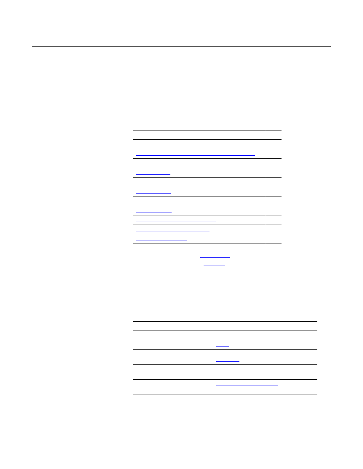
This table contains the changes made to this revision.
Top ic Pa ge
Added information about the Connected Components Workbench software tool. Throughout
Removed information for PLC-5, SLC 500, and MicroLogix 1100/1400 controllers. This information is now
provided in a separate document titled ‘Controller Examples for EtherNet/IP Network Communications
with PowerFlex 750-Series Drives’, publication 750COM-AT001.
In Chapter 1 in the subsection ‘User-Supplied Equipment’ under configuration tool, added Connected
Components Workbench software, a free configuration tool.
In Chapter 4 in the ‘Using Automatic Device Configuration (ADC) with RSLogix 5000 Software, Version
20.00 or Later” subsection, added new information to the introduction, along with a new Important
statement and a new Tip.
manual
14
59
Rockwell Automation Publication 750COM-UM001E-EN-P - October 2013 3
Page 4

Summary of Changes
Notes:
4 Rockwell Automation Publication 750COM-UM001E-EN-P - October 2013
Page 5

Table of Contents
Preface
Getting Started
Installing the Adapter
Configuring the Adapter
Conventions Used in This Manual . . . . . . . . . . . . . . . . . . . . . . . . . . . . . . . . . 9
Rockwell Automation Support . . . . . . . . . . . . . . . . . . . . . . . . . . . . . . . . . . . . . 9
Additional Resources . . . . . . . . . . . . . . . . . . . . . . . . . . . . . . . . . . . . . . . . . . . . . 10
Chapter 1
Components. . . . . . . . . . . . . . . . . . . . . . . . . . . . . . . . . . . . . . . . . . . . . . . . . . . . . 11
Features . . . . . . . . . . . . . . . . . . . . . . . . . . . . . . . . . . . . . . . . . . . . . . . . . . . . . . . . . 12
Compatible Products . . . . . . . . . . . . . . . . . . . . . . . . . . . . . . . . . . . . . . . . . . . . . 13
Required Equipment . . . . . . . . . . . . . . . . . . . . . . . . . . . . . . . . . . . . . . . . . . . . . 13
Safety Precautions . . . . . . . . . . . . . . . . . . . . . . . . . . . . . . . . . . . . . . . . . . . . . . . . 15
Quick Start . . . . . . . . . . . . . . . . . . . . . . . . . . . . . . . . . . . . . . . . . . . . . . . . . . . . . . 16
Chapter 2
Preparing for an Installation. . . . . . . . . . . . . . . . . . . . . . . . . . . . . . . . . . . . . . . 17
Setting the IP Address . . . . . . . . . . . . . . . . . . . . . . . . . . . . . . . . . . . . . . . . . . . . 18
Connecting the Adapter to the Network . . . . . . . . . . . . . . . . . . . . . . . . . . . 20
Applying Power . . . . . . . . . . . . . . . . . . . . . . . . . . . . . . . . . . . . . . . . . . . . . . . . . . 21
Commissioning the Adapter . . . . . . . . . . . . . . . . . . . . . . . . . . . . . . . . . . . . . . 24
Chapter 3
Configuration Tools. . . . . . . . . . . . . . . . . . . . . . . . . . . . . . . . . . . . . . . . . . . . . . 25
Using the PowerFlex 20-HIM-A6 or 20-HIM-C6S HIM to Access
Parameters. . . . . . . . . . . . . . . . . . . . . . . . . . . . . . . . . . . . . . . . . . . . . . . . . . . . 26
Setting the Adapter IP Address . . . . . . . . . . . . . . . . . . . . . . . . . . . . . . . . . . . . 26
Setting the Data Rate . . . . . . . . . . . . . . . . . . . . . . . . . . . . . . . . . . . . . . . . . . . . . 31
Selecting Master-Slave or Peer-to-Peer Hierarchy . . . . . . . . . . . . . . . . . . . 32
Setting a Fault Action . . . . . . . . . . . . . . . . . . . . . . . . . . . . . . . . . . . . . . . . . . . . 38
Setting Web Access Control . . . . . . . . . . . . . . . . . . . . . . . . . . . . . . . . . . . . . . 40
Resetting the Adapter . . . . . . . . . . . . . . . . . . . . . . . . . . . . . . . . . . . . . . . . . . . . 41
Restoring Adapter Parameters to Factory Defaults . . . . . . . . . . . . . . . . . . 41
Viewing the Adapter Status Using Parameters . . . . . . . . . . . . . . . . . . . . . . 42
Updating the Adapter Firmware. . . . . . . . . . . . . . . . . . . . . . . . . . . . . . . . . . . 43
Configuring the I/O
Chapter 4
Using RSLinx Classic . . . . . . . . . . . . . . . . . . . . . . . . . . . . . . . . . . . . . . . . . . . . . 45
ControlLogix Example . . . . . . . . . . . . . . . . . . . . . . . . . . . . . . . . . . . . . . . . . . . 46
Rockwell Automation Publication 750COM-UM001E-EN-P - October 2013 5
Page 6

Table of Contents
Chapter 5
Using the I/O
Using Explicit Messaging
Troubleshooting
About I/O Messaging . . . . . . . . . . . . . . . . . . . . . . . . . . . . . . . . . . . . . . . . . . . . 79
Understanding the ControlLogix Controller I/O Image. . . . . . . . . . . . . 80
Using Logic Command/Status . . . . . . . . . . . . . . . . . . . . . . . . . . . . . . . . . . . . 81
Using Reference/Feedback . . . . . . . . . . . . . . . . . . . . . . . . . . . . . . . . . . . . . . . . 81
Using Datalinks . . . . . . . . . . . . . . . . . . . . . . . . . . . . . . . . . . . . . . . . . . . . . . . . . . 82
Example Ladder Logic Program Information . . . . . . . . . . . . . . . . . . . . . . . 83
ControlLogix Controller Example . . . . . . . . . . . . . . . . . . . . . . . . . . . . . . . . . 84
Chapter 6
About Explicit Messaging . . . . . . . . . . . . . . . . . . . . . . . . . . . . . . . . . . . . . . . . . 92
Performing Explicit Messaging . . . . . . . . . . . . . . . . . . . . . . . . . . . . . . . . . . . . 93
ControlLogix Controller Examples . . . . . . . . . . . . . . . . . . . . . . . . . . . . . . . . 94
Chapter 7
Understanding the Status Indicators . . . . . . . . . . . . . . . . . . . . . . . . . . . . . . 107
ENET Status Indicator . . . . . . . . . . . . . . . . . . . . . . . . . . . . . . . . . . . . . . . . . . 108
LINK Status Indicator. . . . . . . . . . . . . . . . . . . . . . . . . . . . . . . . . . . . . . . . . . . 108
Viewing Adapter Diagnostic Items. . . . . . . . . . . . . . . . . . . . . . . . . . . . . . . . 109
Viewing and Clearing Events . . . . . . . . . . . . . . . . . . . . . . . . . . . . . . . . . . . . . 111
Viewing the Adapter Web Pages
Specifications
Adapter Parameters
Chapter 8
Enabling the Adapter Web Pages . . . . . . . . . . . . . . . . . . . . . . . . . . . . . . . . . 113
Viewing the Web Pages . . . . . . . . . . . . . . . . . . . . . . . . . . . . . . . . . . . . . . . . . . 113
Process Display Pop-up Dialog Box . . . . . . . . . . . . . . . . . . . . . . . . . . . . . . . 116
TCP/IP Configuration Web Page . . . . . . . . . . . . . . . . . . . . . . . . . . . . . . . . 117
Configure E-mail Notification Web Page. . . . . . . . . . . . . . . . . . . . . . . . . . 118
Device Information Pages . . . . . . . . . . . . . . . . . . . . . . . . . . . . . . . . . . . . . . . . 121
Appendix A
Communications. . . . . . . . . . . . . . . . . . . . . . . . . . . . . . . . . . . . . . . . . . . . . . . . 125
Regulatory Compliance. . . . . . . . . . . . . . . . . . . . . . . . . . . . . . . . . . . . . . . . . . 125
Appendix B
How Parameters Are Organized . . . . . . . . . . . . . . . . . . . . . . . . . . . . . . . . . . 127
Parameter List . . . . . . . . . . . . . . . . . . . . . . . . . . . . . . . . . . . . . . . . . . . . . . . . . . 128
6 Rockwell Automation Publication 750COM-UM001E-EN-P - October 2013
Page 7

Appendix C
Table of Contents
EtherNet/IP Objects
Logic Command/Status Words:
PowerFlex 750-Series Drives
History of Changes
Supported Data Types . . . . . . . . . . . . . . . . . . . . . . . . . . . . . . . . . . . . . . . . . . . 137
Identity Object. . . . . . . . . . . . . . . . . . . . . . . . . . . . . . . . . . . . . . . . . . . . . . . . . . 138
Assembly Object . . . . . . . . . . . . . . . . . . . . . . . . . . . . . . . . . . . . . . . . . . . . . . . . 139
Register Object. . . . . . . . . . . . . . . . . . . . . . . . . . . . . . . . . . . . . . . . . . . . . . . . . . 140
PCCC Object . . . . . . . . . . . . . . . . . . . . . . . . . . . . . . . . . . . . . . . . . . . . . . . . . . 141
DPI Device Object . . . . . . . . . . . . . . . . . . . . . . . . . . . . . . . . . . . . . . . . . . . . . . 145
DPI Parameter Object . . . . . . . . . . . . . . . . . . . . . . . . . . . . . . . . . . . . . . . . . . . 148
DPI Fault Object. . . . . . . . . . . . . . . . . . . . . . . . . . . . . . . . . . . . . . . . . . . . . . . . 154
DPI Alarm Object. . . . . . . . . . . . . . . . . . . . . . . . . . . . . . . . . . . . . . . . . . . . . . . 156
DPI Diagnostic Object . . . . . . . . . . . . . . . . . . . . . . . . . . . . . . . . . . . . . . . . . . 158
DPI Time Object . . . . . . . . . . . . . . . . . . . . . . . . . . . . . . . . . . . . . . . . . . . . . . . 160
Host DPI Parameter Object. . . . . . . . . . . . . . . . . . . . . . . . . . . . . . . . . . . . . . 162
TCP/IP Interface Object . . . . . . . . . . . . . . . . . . . . . . . . . . . . . . . . . . . . . . . . 168
Ethernet Link Object. . . . . . . . . . . . . . . . . . . . . . . . . . . . . . . . . . . . . . . . . . . . 170
Appendix D
Logic Command Word . . . . . . . . . . . . . . . . . . . . . . . . . . . . . . . . . . . . . . . . . . 173
Logic Status Word . . . . . . . . . . . . . . . . . . . . . . . . . . . . . . . . . . . . . . . . . . . . . . 174
Appendix E
750COM-UM001D-EN-P, February 2012 . . . . . . . . . . . . . . . . . . . . . . . 175
750COM-UM001C-EN-P, November 2011 . . . . . . . . . . . . . . . . . . . . . . 176
750COM-UM001B-EN-P, October 2011 . . . . . . . . . . . . . . . . . . . . . . . . 176
750COM-UM001A-EN-P, January 2009 . . . . . . . . . . . . . . . . . . . . . . . . . 176
Glossary
Index
Rockwell Automation Publication 750COM-UM001E-EN-P - October 2013 7
Page 8

Table of Contents
8 Rockwell Automation Publication 750COM-UM001E-EN-P - October 2013
Page 9

Preface
This manual provides information about the EtherNet/IP adapter embedded on
the Main Control Board in PowerFlex® 755 drives, and using it for network
communication.
Conventions Used in This Manual
Rockwell Automation Support
The following conventions are used throughout this manual:
• Parameter names are shown in the format Parameter xx - [*]. The xx
represents the parameter number. The * represents the parameter name—
for example Parameter 01 - [DL From Net Cfg 01].
• The drive firmware revision number (FRN) is displayed as FRN X.xxx,
where ‘X’ is the major revision number and ‘xxx’ is the minor revision
number.
• The dialog box images in this manual resulted from using the following
software:
– RSLinx® Classic software, version 2.52
– RSLogix™ 5000 software, version 16.00 (for Automatic Device
Configuration information only, RSLogix 5000, version 20.00)
Different versions of the software may have dialog boxes that vary in
appearance, and differences in procedures.
Rockwell Automation offers support services worldwide, with over 75 sales and
support offices, over 500 authorized distributors, and over 250 authorized
systems integrators located through the United States alone. In addition,
Rockwell Automation representatives are in every major country in the world.
Local Product Support
Contact your local Rockwell Automation representative for the following:
• Sales and order support
• Product technical training
• Wa rr an t y su p p or t
• Support service agreements
Technical Product Assistance
For technical assistance, please review the information in Chapter 7,
Troubleshooting, first. If you still have problems, then access the Allen-Bradley
Technical Support website at http://www.ab.com/support/abdrives
Rockwell Automation.
Rockwell Automation Publication 750COM-UM001E-EN-P - October 2013 9
or contact
Page 10

Preface
Additional Resources
Resource Description
EtherNet/IP Media Planning and Installation Manual, ODVA publication 148
EtherNet/IP Network Infrastructure Guidelines, ODVA Publication 35
Ethernet Design Considerations Reference Manual, publication ENET-RM002
Connected Components Workbench website http://www.ab.com/support/abdrives/webupdate/
software.html, and online help
DriveExplorer website http://www.ab.com/drives/driveexplorer, and online help
DriveExecutive website http://www.ab.com/drives/drivetools
PowerFlex 750-Series Drive Installation Instructions, publication 750-IN001 Information on installing, programming, and technical data of PowerFlex®
PowerFlex 750-Series Drive Programming Manual, publication 750-PM001
PowerFlex 750-Series Drive Technical Data, publication 750-TD001
PowerFlex 20-HIM-A6/-C6S HIM (Human Interface Module) User Manual, publication 20HIM-UM001 Information on the installation and use of PowerFlex 20-HIM-A6 or 20-HIM-
Getting Results with RSLinx Guide, publication LINX-GR001, and online help
RSLogix 5000 PIDE Autotuner Getting Results Guide, publication PIDE-GR001
EtherNet/IP Modules in Logix5000 Control Systems User Manual, publication ENET-UM001 Information on using the ControlLogix® 1756-ENBT or 1756-EN2T
Controller Examples for EtherNet/IP Network Communications with PowerFlex 750-Series Drives,
publication 750COM-AT001
(2)
These documents contain additional information concerning related products
from Rockwell Automation.
(1)
(1)
, and online help
(2)
(2)
(2)
, and online help
Information on the planning, installation, and techniques used to implement
an EtherNet/IP network.
Information on the Connected Components Workbench™ software tool—
and includes a link for free software download.
Information on using the DriveExplorer™ software tool.
Information on using the DriveExecutive™ software tool.
750-Series Drives
C6S HIMs.
Information on using RSLinx Classic software.
(2)
Information on using the RSLogix 5000 software tool.
communication modules with your Logix 5000 controller and communicating
with various devices on the EtherNet/IP network.
Information on using PLC-5®, SLC™ 500, and MicroLogix™ 1100/1400
controllers with PowerFlex 750-Series drives that are equipped with a
20-750-ENETR Dual-port EtherNet/IP option module or embedded EtherNet/
IP adapter (PowerFlex 755 drive only).
(1) Use this link to the ODVA EtherNet/IP library: http://odva.org/Home/ODVATECHNOLOGIES/EtherNetIP/EtherNetIPLibrary/tabid/76/Defa ult.aspx
(2) The online help is installed with the software.
You can view or download publications at http://
www.rockwellautomation.com/literature. To order paper copies of technical
documentation, contact your local Rockwell Automation distributor or sales
representative.
To find your local Rockwell Automation distributor or sales representative, visit
http://www.rockwellautomation.com/locations
For information such as firmware updates or answers to drive-related questions,
go to the Drives Service & Support web site at http://www.ab.com/support/
abdrives and click the Downloads or Knowledgebase link.
.
10 Rockwell Automation Publication 750COM-UM001E-EN-P - October 2013
Page 11
Chapter 1
0
5
4
9
3
8
2
7
1
6
0
5
4
9
3
8
2
7
1
6
0
5
4
9
3
8
2
7
1
6
➊
➍
➌
➋
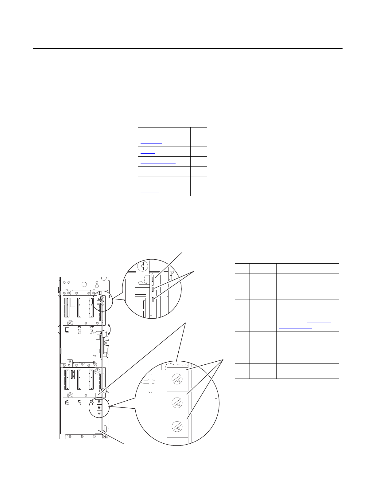
Item Part Description
➊
Status
Indicators
Two LEDs that indicate the status
of the adapter and network
communication. See Chapter 7,
Troubleshooting.
➋
IP Address
Switche s
Sets the IP address of the
embedded adapter when not
using a BOOTP server or adapter
parameters. See Setting the IP
Address on page 18 for details.
➌
Ethernet
Conne ctor
An RJ-45 connector for the
Ethernet cable. The connector is
CAT-5 complia nt to ensure rel iable
data transfer on 100Base-TX
Ethernet connections.
➍
DPI Port 2 Cable connection for handheld
and remote options.
Drive Control Pod
Drive STS Indicator
Components shown with HIM bezel
open and drive cover removed.
Getting Started
The EtherNet/IP adapter, embedded on the Main Control Board in PowerFlex
755 drives, is used for network communication.
Top ic Pag e
Components
Featu res
Compatible Products
Required Equipment
Safety Precautions 15
Quick Start 16
11
12
13
13
Components
Rockwell Automation Publication 750COM-UM001E-EN-P - October 2013 11
Page 12

Chapter 1 Getting Started
TIP
Features
The features of the embedded EtherNet/IP adapter include the following:
• Switches to set an IP address before applying power to the drive—or you
can disable the switches and use a BOOTP (Bootstrap Protocol) server or
adapter parameters to configure the IP address.
• Compatibility with the following configuration tools to configure the
embedded EtherNet/IP adapter and host drive:
– PowerFlex 20-HIM-A6 or 20-HIM-C6S HIM (Human Interface
Module) on the drive, if available
– Connected Components Workbench software, version1.02 or later
– DriveExplorer software, version 6.01 or later
– DriveExecutive software, version 5.01 or later.
• Status indicators that report the status of the embedded EtherNet/IP
adapter and network communications. They are visible when the drive
cover is open or closed.
• Parameter-configured 32-bit Datalinks in the I/O to meet application
requirements (16 Datalinks to write data from the network to the drive,
and 16 Datalinks to read data to the network from the drive).
• Explicit Messaging support.
• Master-Slave or Peer-to-Peer hierarchy that can be configured to transmit
data to and from either a controller or another PowerFlex 750-Series drive
on the network.
• Supports ‘Integrated Motion on the EtherNet/IP network’ operation for
the PowerFlex 755 drive, firmware revision 2.003 or later. For details to set
up ‘Integrated Motion on the EtherNet/IP network’ operation, see
Integrated Motion on the EtherNet/IP Network User Manual,
publication MOTION-UM003
For best reliability in ‘Integrated Motion on the EtherNet/IP network’
applications, we recommend that you always use Rockwell
Automation Cat5e shielded Ethernet cable.
• User-defined fault actions to determine how the embedded EtherNet/IP
adapter and its host PowerFlex 755 drive respond to the following:
– I/O messaging communication disruptions (Comm Flt Action)
– Controllers in Idle mode (Idle Flt Action)
– Peer device communication disruptions (Peer Flt Action)
– Explicit messaging disruptions for drive control via PCCC, the CIP
Register Object or the CIP Assembly Object (Msg Flt Action)
.
12 Rockwell Automation Publication 750COM-UM001E-EN-P - October 2013
Page 13

Getting Started Chapter 1
• Automatic Device Configuration (ADC), which is an ‘RSLogix 5000
software, version 20.00, feature’ that supports the automatic download of
configuration data. This occurs after the Logix controller establishes an
EtherNet/IP network connection to a PowerFlex 755 drive (firmware
revision 4.001 or later) and its associated peripherals.
• Web pages, viewed by using a web browser, that show information about
the embedded EtherNet/IP adapter, its host drive, and DPI devices
connected to the drive.
• Configured e-mail messaging to desired addresses when selected drive
faults occur and/or are cleared, and/or when the embedded EtherNet/IP
adapter takes a communication or idle fault action.
• Access to any PowerFlex drive and its connected peripherals on the
network to which the embedded EtherNet/IP adapter is connected.
Compatible Products
Required Equipment
At the time of publication, the embedded EtherNet/IP adapter is compatible
with Allen-Bradley PowerFlex 755 drives.
Some of the equipment that is required for use with the embedded EtherNet/IP
adapter is shipped with the drive, but some you must supply yourself.
Equipment Shipped with the Drive
Since the EtherNet/IP adapter is embedded on the Main Control Board in the
PowerFlex 755 drive, it is always an integral part of the drive and, therefore, does
not require installation instructions.
User-Supplied Equipment
To configure the embedded EtherNet/IP adapter, you must supply the following:
❑ A small screwdriver
❑ Ethernet cable (for details, see the EtherNet/IP Media Planning and
Installation Manual, ODVA publication 148 available on the ODVA
website at http://odva.org/Home/ODVATECHNOLOGIES/
EtherNetIP/EtherNetIPLibrary/tabid/76/Default.aspx)
❑ Ethernet switch (for details, see the Ethernet Design Considerations
Reference Manual, publication ENET-RM002
Rockwell Automation Publication 750COM-UM001E-EN-P - October 2013 13
)
Page 14

Chapter 1 Getting Started
❑ Drive and embedded adapter configuration tool, such as the following:
– PowerFlex 20-HIM-A6 or 20-HIM-C6S HIM
– Connected Components Workbench software, version 1.02 or later
Connected Components Workbench is the recommended stand-alone
software tool for use with PowerFlex drives. You can obtain a free copy
by:
• Internet download at http://www.ab.com/support/abdrives/
webupdate/software.html
• Requesting a DVD at http://www.ab.com/onecontact/
controllers/micro800/
Your local distributor may also have copies of the DVD available.
Connected Components Workbench software cannot be used to
configure SCANport-based drives or Bulletin 160 drives.
– DriveExplorer software, version 6.01 or later
This software tool has been discontinued and is now available as
freeware at http://www.ab.com/support/abdrives/webupdate/
software.html. There are no plans to provide future updates to this tool
and the download is being provided ‘as-is’ for users that lost their
DriveExplorer CD, or need to configure legacy products not supported
by Connected Components Workbench software.
– DriveExecutive software, version 5.01 or later
A Lite version of DriveExecutive software ships with RSLogix 5000,
RSNetWorx MD, FactoryTalk AssetCentre, and ItelliCENTER
software. All other versions are purchasable items:
• 9303-4DTE01ENE Drive Executive software
• 9303-4DTS01ENE DriveTools SP Suite (includes
DriveExecutive and DriveObserver software)
• 9303-4DTE2S01ENE DriveExecutive software upgrade to
DriveTools SP Suite (adds DriveObserver software)
DriveExecutive software updates (patches, and so forth) can be obtained
at http://www.ab.com/support/abdrives/webupdate/software.html
is highly recommended that you periodically check for and install the
latest update.
– BOOTP, version 2.1 or later, for network setup only
❑ Controller configuration software, such as RSLogix 5000 software, version
20.00 and earlier, or Studio 5000™ Logix Designer application, version
21.00 and later
❑ A computer connection to the EtherNet/IP network
. It
14 Rockwell Automation Publication 750COM-UM001E-EN-P - October 2013
Page 15
Getting Started Chapter 1
Safety Precautions
Please read the following safety precautions carefully.
ATTENTION: Risk of injury or equipment damage exists. Only personnel familiar
with drive and power products and the associated machinery should plan or
implement the installation, start up, configuration, and subsequent
maintenance of the drive using this embedded adapter. Failure to comply may
result in injury and/or equipment damage.
ATTENTION: Risk of equipment damage exists. The embedded adapter contains
electrostatic discharge (ESD) sensitive parts that can be damaged if you do not
follow ESD control procedures. Static control precautions are required when
handling the adapter. If you are unfamiliar with static control procedures, see
Guarding Against Electrostatic Damage, publication 8000-4.5.2
ATTENTION: Risk of injury or equipment damage exists. If the adapter is
transmitting control I/O to the drive, the drive may fault when you reset the
adapter. Determine how your drive will respond before resetting the adapter.
ATTENTION: Risk of injury or equipment damage exists. Embedded adapter
Parameters 54 - [Comm Flt Action], 55 - [Idle Flt Action], 56 - [Peer Flt
Action], and 57 - [Msg Flt Action] let you determine the action of the adapter
and drive if I/O communication is disrupted, the controller is idle, peer I/O is
disrupted, or explicit messaging for drive control is disrupted. By default, these
parameters fault the drive. You may configure these parameters so that the drive
continues to run, however, precautions should be taken to verify that the settings
of these parameters do not create a risk of injury or equipment damage. When
commissioning the drive, verify that your system responds correctly to various
situations (for example, a disconnected cable or a controller in idle state).
.
ATTENTION: Risk of injury or equipment damage exists. When a system is
configured for the first time, there may be unintended or incorrect machine
motion. Disconnect the motor from the machine or process during initial system
testing.
ATTENTION: Risk of injury or equipment damage exists. The examples in this
publication are intended solely for purposes of example. There are many
variables and requirements with any application. Rockwell Automation does not
assume responsibility or liability (to include intellectual property liability) for
actual use of the examples shown in this publication.
Rockwell Automation Publication 750COM-UM001E-EN-P - October 2013 15
Page 16

Chapter 1 Getting Started
Quick Start
This section is provided to help experienced users quickly start using the
embedded EtherNet/IP adapter. If you are unsure how to complete a step, refer to
the referenced chapter.
Step Action See
1 Review the safety precautions for the adapter. Throughout this manual
2 Verify that the PowerFlex drive is properly installed. PowerFlex 750-Series AC Drive
3 Set the adapter IP address.
a. When using the adapter switches, set the IP address now and
proceed with step 4.
When using a BOOTP server, or adapter parameters instead to set the
IP address, first perform step 3b and 3c, and all of step 4. Then
proceed with step 5.
b. Verify that the PowerFlex drive is not powered.
c. Connect the embedded EtherNet/IP adapter to the network with an
Ethernet cable.
4Apply power to the drive.
a. Replace the drive cover or close the drive door.
b. Apply power to the drive.
The embedded EtherNet/IP adapter receives power from the drive.
The status indicators should be green. If they flash red, there is a
problem. See Chapter 7
c. Configure and verify key drive parameters.
5 Configure the adapter for your application.
Set embedded EtherNet/IP adapter parameters for the following functions
as required by your application:
• IP address, subnet mask, and gateway address (only when not using
adapter switches)
• Data rate
• I/O configuration
• Master-Slave or Peer-to-Peer hierarchy
• Fault actions
• Web enable and features
6 Configure the controller to communicate with the adapter.
Use a controller configuration tool, such as RSLogix software, to configure
the master on the network to recognize the embedded EtherNet/IP adapter
and drive.
7 Create a ladder logic program.
Use a controller configuration tool, such as RSLogix software, to create a
ladder logic program that enables you to do the following:
• Control the drive, via the embedded EtherNet/IP adapter, by using I/O.
• Monitor or configure the drive by using explicit messages.
, Troubleshooting.
Installation Instructions,
publication 750-IN001
,
Chapter 2
Installing the Adapter
,
Chapter 2
Installing the Adapter
Chapter 3
,
Configuring the Adapter
,
Chapter 4
Configuring the I/O
,
Chapter 5
Using the I/O
,
Chapter 6
Using Explicit Messaging
16 Rockwell Automation Publication 750COM-UM001E-EN-P - October 2013
Page 17

Chapter 2
Installing the Adapter
Since the EtherNet/IP adapter is embedded on the Main Control Board in the
PowerFlex 755 drive, the only required adapter installation is setting its IP
address and connecting it to the network.
Top ic Pag e
Preparing for an Installation 17
Setting the IP Address
Connecting the Adapter to the Network 20
Applying Power 21
Commissioning the Adapter
18
24
Preparing for an Installation
Before installing the embedded EtherNet/IP adapter, do the following:
• Make sure the Ethernet switch is the correct type. A ‘managed’ switch that
supports IGMP snooping is usually recommended. An ‘unmanaged’
switch can be used instead if RSLogix 5000 software, version 18.00 or
later, is used and all devices on the network are configured for ‘unicast’
I/O. For more details, see the following documents:
– EtherNet/IP Media Planning and Installation Manual,
ODVA publication 148
– EtherNet/IP Network Infrastructure Guidelines,
ODVA publication 35
– Ethernet Design Considerations Reference Manual,
publication ENET-RM002
• Understand IGMP Snooping/Ethernet Switches
The embedded EtherNet/IP adapter is a multicast device. In most
situations, an IGMP snooping (managed) switch is required. If more than
one or two embedded EtherNet/IP adapters are connected to the switch, a
managed switch is required—otherwise the drive may fault on a Net IO
Timeout network loss. The embedded EtherNet/IP adapter, RSLogix
5000 software version 18 or later, and a ControlLogix or CompactLogix
controller will support unicast. Unicast setup is required when adding the
drive to the I/O. When all embedded EtherNet/IP adapters are set up as
unicast devices, then an IGMP snooping (managed) switch is not needed.
Much of EtherNet/IP implicit (I/O) messaging uses IP multicast to
distribute I/O control data, which is consistent with the CIP producer/
Rockwell Automation Publication 750COM-UM001E-EN-P - October 2013 17
Page 18

Chapter 2 Installing the Adapter
IMPORTANT
consumer model. Historically, most switches have treated multicast
packets the same as broadcast packets. That is, all multicast packets are retransmitted to all ports.
IGMP snooping constrains the flooding of multicast traffic by dynamically
configuring switch ports so that multicast traffic is forwarded only to ports
associated with a particular IP multicast group.
Switches that support IGMP snooping (managed switches) ‘learn’ which
ports have devices that are part of a particular multicast group and only
forward the multicast packets to the ports that are part of the multicast
group.
Be careful as to what level of support a switch has of IGMP snooping.
Some layer 2 switches that support IGMP snooping require a router
(which could be a layer 3 switch) to send out IGMP polls to learn what
devices are part of the multicast group. Some layer 2 switches can use
IGMP snooping without a router sending polls. If your control system is a
standalone network or is required to continue performing if the router is
out of service, make sure the switch you are using supports IGMP
snooping without a router being present.
Setting the IP Address
• See Appendix
embedded EtherNet/IP adapter.
• Verify that you have all required equipment. See Required Equipment
page 13.
There are several ways to configure the embedded EtherNet/IP adapter IP address:
• Adapter Rotary Switches — Use the switches when working on a simple,
isolated network (for example, 192.168.1.xxx) that has other products
with switches to set their IP addresses, does not need to be accessed from
outside the network, and you prefer a simplified node addressing method.
The three adapter switches are read when the drive powers up, and
represent three decimal digits from top to bottom. If set to a valid address
(001…254), the adapter will use that value as the lower octet of its IP
address (192.168.1.xxx, where xxx = rotary switch settings), along with a
subnet mask of 255.255.255.0 and there will be no gateway configured.
Also, the setting for adapter Parameter 36 - [BOOTP] is automatically
ignored.
See Figure 1 on page 19
their related descriptions.
A for the number of CIP connections supported by the
on
and its accompanying table for switch settings and
When using the adapter rotary switches, set the IP address before
power is applied because the adapter uses the IP address it detects
when it first receives power.
18 Rockwell Automation Publication 750COM-UM001E-EN-P - October 2013
Page 19
TIP
IMPORTANT
Ones
Posi tion
Hundreds
Posi tion
Ten s
Posi tion
Installing the Adapter Chapter 2
•Adapter Parameters — Use adapter parameters when you want more
flexibility in setting up the IP address, or need to communicate outside the
control network using a gateway. To use parameters as the source for the IP
address, the rotary switches must be set to a value other than 001…254 or
888, and Parameter 36 - [BOOTP] must be set to ‘0’ (disabled). The IP
address, subnet mask, and gateway addresses will then come from the
values set using the associated adapter parameters.
•BOOTP — Use BOOTP, the default, when you want to configure a
temporary IP addresses, subnet mask, and gateway address for the adapter
using a BOOTP server. To use BOOTP as the source for the IP address,
the rotary switches must be set to a value other than 001…254 or 888, and
Parameter 36 - [BOOTP] must be set to ‘1’ (enabled).
Note the adapter’s hardware Ethernet Address (MAC) on the drive’s Main
Control Board, which will be used in step 6 when configuring the BOOTP
server (see Using a BOOTP Server
on page 26 for details).
If the PowerFlex 755 drive is connected to a Stratix 6000 or Stratix 8000
managed Ethernet switch and the drive is set for BOOTP mode, the
‘dynamic IP address assignment by port’ (Stratix 6000) or ‘DHCP
persistence’ (Stratix 8000) feature will set the IP address for the drive.
For more details, see the Stratix 6000 Ethernet Managed Switch User
Manual, publication 1783-UM001
or the Stratix 8000 and Stratix 8300
Ethernet Managed Switches User Manual, publication 1783-UM003
Regardless of the method used to set the adapter IP address, each node on the
EtherNet/IP network must have a unique IP address. To change an IP address,
you must set the new value and then remove and reapply power to (or reset)
the adapter.
.
Figure 1 - Setting the IP Address Switches
5
6
4
7
3
8
2
9
1
0
5
6
4
7
3
8
2
9
1
0
5
6
4
7
3
8
2
9
1
0
Settings Description
001…254 The adapter will use the rotary switch settings for the IP address (192.168.1.xxx, where xxx = rotary
888 Resets the adapter IP address function to factory defaults. Thereafter, the drive must be powered
Any other
setting
Rockwell Automation Publication 750COM-UM001E-EN-P - October 2013 19
switch settings). The value stored in Parameter 36 - [BOOTP] is automatically ignored.
down, the switches set to a correct value (001…254), and then the drive must be powered up again
to accept the new address.
Disables the rotary switches and requires using Parameter 36 - [BOOTP] to select the BOOTP server
as the source for the IP address or, if disabled, selec ts the adapter parameters as the source.
Page 20
Chapter 2 Installing the Adapter
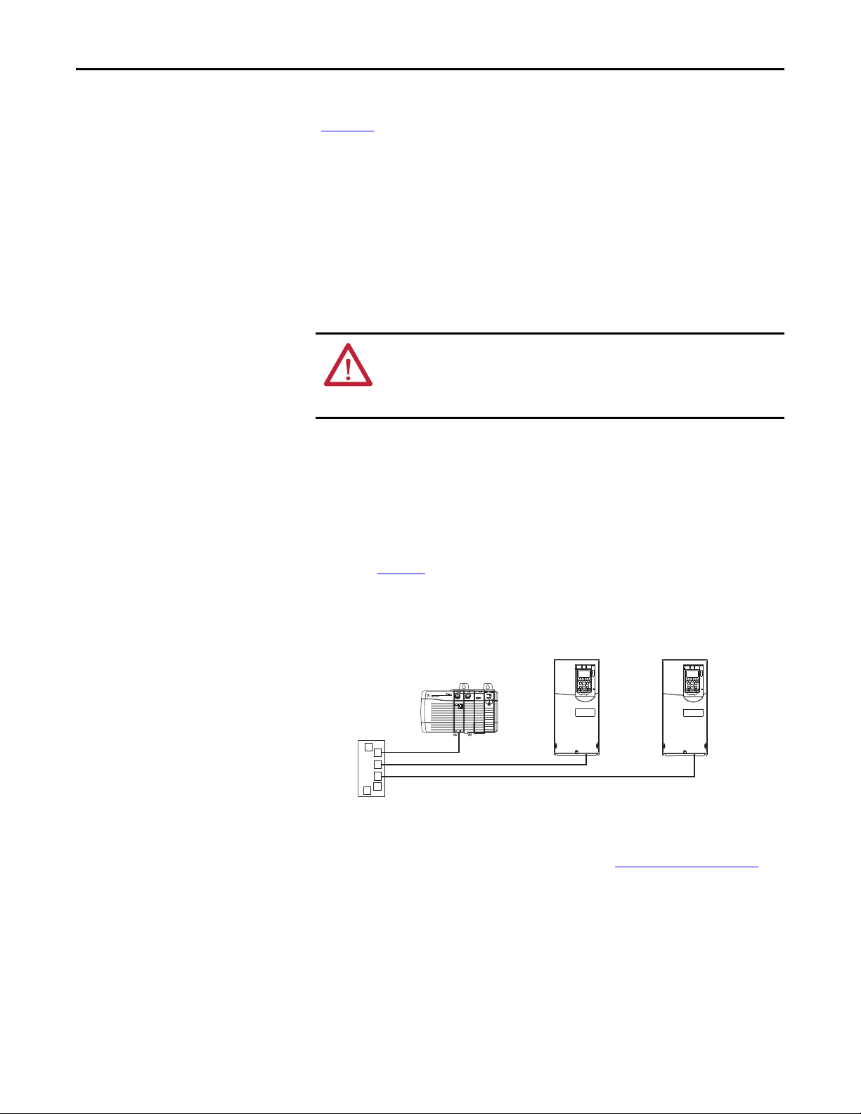
Ethernet
Switch
Controller
(ControlLogix s hown with
1756-ENBT Bridge)
PowerFlex 755 Drives
(each with embedded EtherNet/IP adapter)
The switch settings can be verified by viewing Diagnostic Device Item number 68
(page 111
Also, you can use Parameter 37 - [Net Addr Src], a read-only parameter, to
verify the selected setting for Parameter 36 - [BOOTP].
) with any of the following drive configuration tools:
• PowerFlex 20-HIM-A6 or 20-HIM-C6S HIM
• Connected Components Workbench software, version 1.02 or later
• DriveExplorer software, version 6.01 or later
• DriveExecutive software, version 5.01 or later
Connecting the Adapter to the Network
ATTENTION: Risk of injury or death exists. The PowerFlex drive may contain high
voltages that can cause injury or death. Remove power from the drive, and then
verify power has been discharged before connecting the embedded EtherNet/IP
adapter to the network.
1. Remove power from the drive.
2. Remove the drive cover and lift up the drive HIM bezel to its open
position to access the drive control pod.
3. Use static control precautions.
4. Connect one end of an Ethernet cable to the network.
See Figure 2
Figure 2 - Connecting the Ethernet Cable to the Network
for an example of wiring to an EtherNet/IP network.
5. Route the other end of the Ethernet cable through the bottom of the
PowerFlex 755 drive, and insert the cable plug into the embedded
EtherNet/IP adapter mating socket (item 3 in Components
20 Rockwell Automation Publication 750COM-UM001E-EN-P - October 2013
on page 11).
Page 21
Installing the Adapter Chapter 2
➊
➋
➌
Applying Power
ATTENTION: Risk of equipment damage, injury, or death exists. Unpredictable
operation may occur if you fail to verify that parameter settings are compatible
with your application. Verify that settings are compatible with your application
before applying power to the drive.
Install the drive cover, and apply power to the drive. The embedded EtherNet/IP
adapter receives its power from the drive. When you apply power to the
embedded EtherNet/IP adapter for the first time, its ENET status indicator
should be steady green or flashing green after an initialization. If it is red, there is
a problem. See Chapter 7
Start-Up Status Indications
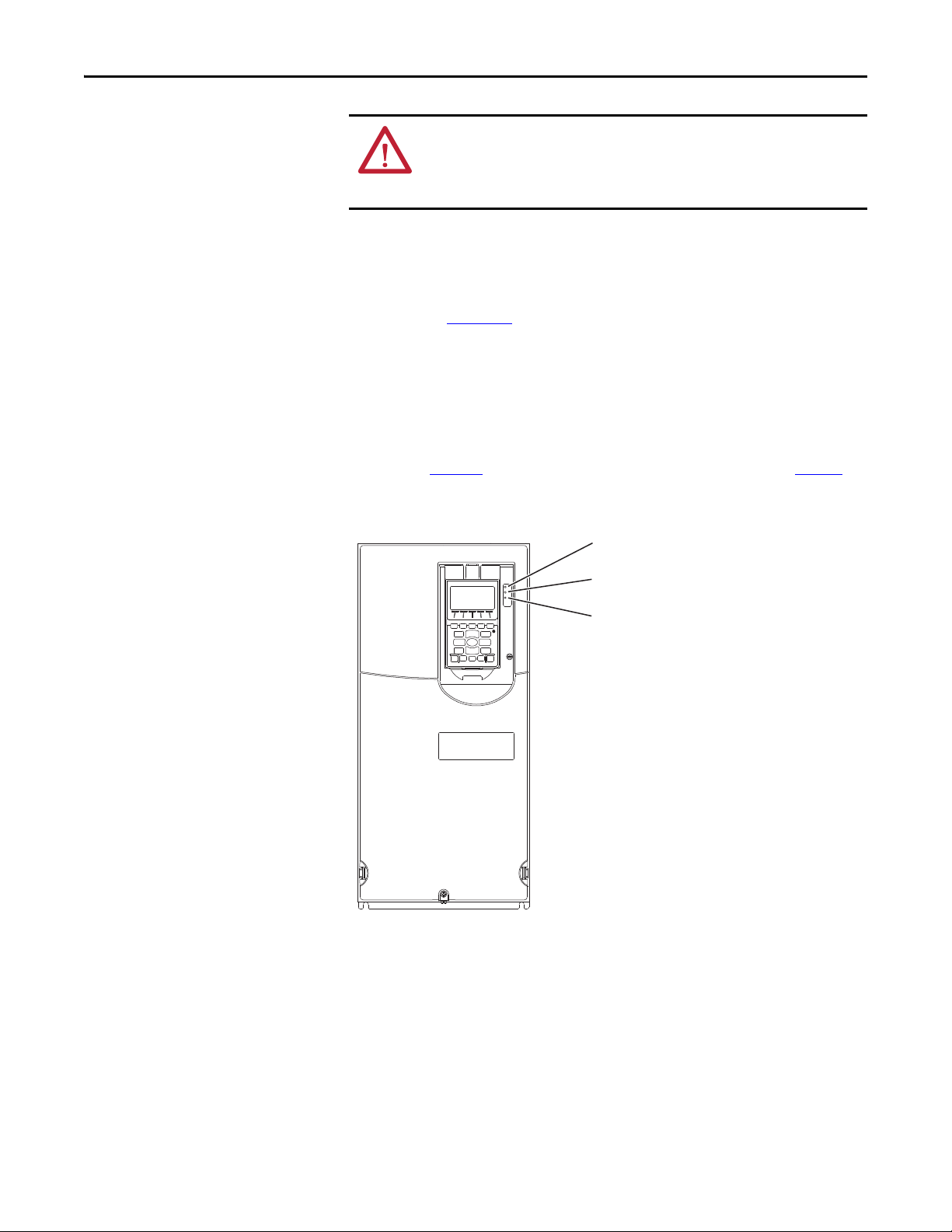
After power has been applied, the drive STS (status) indicator and the embedded
EtherNet/IP adapter ENET and LINK status indicators can be viewed on the front
of the drive (Figure 3
Figure 3 - Drive and Adapter Status Indicators
, Troubleshooting.
). Possible start-up status indications are shown in Ta b l e 1 .
Rockwell Automation Publication 750COM-UM001E-EN-P - October 2013 21
Page 22

Chapter 2 Installing the Adapter
Item Name Color State Description
STS
➊
(Status)
ENET Unlit Off Adapter and/or network is not powered, adapter is not properly connected to the network, or adapter
➋
LINK Unlit Off Adapter is not powered or is not transmitting on the network.
➌
Green Flashing Drive ready but not running, and no faults are present.
Yellow Flashing When running, a type 2 (non-configurable) alarm condition exists – drive continues to run. When stopped,
Red Flashing A major fault has occurred. Drive will stop. Drive cannot be started until fault condition is cleared.
Red/Yellow Flashing Alternately A minor fault has occurred. Use drive parameter 950 - [Minor Flt Config] to enable. If not enabled, acts like
Yellow/Green Flashing Alternately When running, a type 1 alarm exists.
Green/Red Flashing Alternately Drive is firmware updating.
Red Flashing An EtherNet/IP connection has timed out.
Red/Green Flashing Alternately Adapter is performing a self-test.
Green Flashing Adapter is properly connected, but is not communicating with any devices on the network.
Green Flashing Adapter is properly connected and transmitting data packets on the network.
Table 1 - Drive and Adapter Start-Up Status Indications
Drive STS Indicator
Steady Drive running, no faults are present.
a start inhibit condition exists and the drive cannot be started (see drive parameter 933 - [Start Inhibit]).
Steady A type 1 (user configurable) alarm condition exists, but the drive continues to run.
Steady A non-resettable fault has occurred.
a major fault. When running, the drive continues to run. System is brought to a stop under system control.
The fault must be cleared to continue.
Embedded EtherNet/IP Adapter Status Indicators
needs an IP address.
Steady Adapter failed the duplicate IP address detection test.
Steady Adapter is properly connected and communicating on the network.
Steady Adapter is properly connected, but is not transmitting on the network.
After verifying correct operation, swing down the drive HIM bezel to its closed
position and install the drive cover. For more details on status indicator
operation, see page 108
.
Configuring and Verifying Key Drive Parameters
The PowerFlex 755 drive can be separately configured for the control and
Reference functions in various combinations. For example, you could set the
drive to have its control come from a peripheral or terminal block with the
Reference coming from the network. Or you could set the drive to have its
control come from the network with the Reference coming from another
peripheral or terminal block. Or you could set the drive to have both its control
and Reference come from the network.
The following steps in this section assume that the drive will receive the Logic
Command and Reference from the network.
1. Verify that drive Parameter 301 - [Access Level] is set to ‘1’ (Advanced) or
‘2’ (Expert) to access the required parameters in this procedure.
22 Rockwell Automation Publication 750COM-UM001E-EN-P - October 2013
Page 23
Installing the Adapter Chapter 2
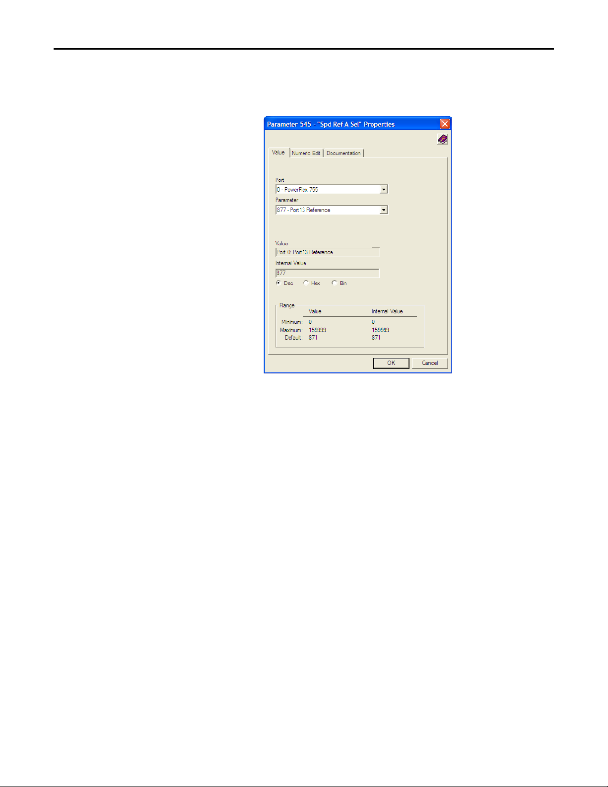
2. Use drive Parameter 545 - [Speed Ref A Sel] to set the drive speed
Reference.
a. Set the Port field to ‘0 - PowerFlex 755’ as shown below.
b. Set the Parameter field to point to the port in which the embedded
EtherNet/IP adapter is located (always ‘Port 13 Reference’ – the drive
port dedicated to the embedded EtherNet/IP adapter).
The number ‘877’ in the Parameter field of the example dialog box
above is the parameter in the drive that points to the port.
3. Verify that drive Parameter 930 - [Speed Ref Source] is reporting that the
source of the Reference to the drive (Port 0) is the port in which the
embedded EtherNet/IP adapter resides (always ‘Port 13 Reference’).
This ensures that any Reference commanded from the network can be
monitored by using drive Parameter 002 - [Commanded SpdRef ]. If a
problem occurs, this verification step provides the diagnostic capability to
determine whether the drive/embedded adapter or the network is the
cause.
4. If hard-wired discrete digital inputs are not used to control the drive, verify
that all unused digital input drive parameters are set to ‘0’ (Not Used).
Rockwell Automation Publication 750COM-UM001E-EN-P - October 2013 23
Page 24

Chapter 2 Installing the Adapter
IMPORTANT
Commissioning the Adapter
To commission the embedded EtherNet/IP adapter, you must set a unique IP
address. See the Glossary
switches, see Setting the IP Address
switches, a BOOTP server or adapter parameters can be used to set the IP address
after connecting the adapter to the network and applying power to the drive.
By default, the adapter is configured so that you must set the IP address using a
BOOTP server. For details, see Using a B OOTP Ser ver
address using adapter parameters, see Using Adapter Parameters
New settings for some adapter parameters (for example, Parameters 38 - [IP
Addr Cfg 1] through 41 - [IP Addr Cfg 4]) are recognized only when power is
applied to the adapter or it is reset. After you change parameter settings, cycle
power or reset the adapter.
for details about IP addresses. When using the adapter
on page 18 for details. When not using these
on page 26. To set the IP
on page 30.
24 Rockwell Automation Publication 750COM-UM001E-EN-P - October 2013
Page 25
Chapter 3
Configuring the Adapter
This chapter provides instructions and information for setting the parameters to
configure the embedded EtherNet/IP adapter.
Top ic Pag e
Configuration Tools
Using the PowerFlex 20-HIM-A6 or 20-HIM-C6S HIM to Access Parameters
Setting the Adapter IP Address
Setting the Data Rate 31
Selecting Master-Slave or Peer-to-Peer Hierarchy 32
Setting a Fault Action
Setting Web Access Control 40
Resetting the Adapter 41
Restoring Adapte r Parameters to Factory Defaults
Viewing the Adapter Status Using Parameters 42
Updating the Adapter Firmware 43
25
26
26
38
41
Configuration Tools
For a list of parameters, see Appendix
terms in this chapter, see the Glossary
The embedded EtherNet/IP adapter stores parameters and other information in
its own nonvolatile storage (NVS) memory. You must, therefore, access the
adapter to view and edit its parameters. The following tools can be used to access
the adapter parameters.
Too l Se e
PowerFlex 20-HIM-A6 or 20-HIM-C6S HIM page 26
BOOTP server page 26
Connected Components Workbench software,
version 1.02 or later
DriveExplorer software,
version 6.01 or later
DriveExecutive software,
version 5.01 or later
B, Adapter Parameters. For definitions of
.
http://www.ab.com/support/abdrives/webupdate/
software.html, or online help (installed with the software)
http://www.ab.com/drives/driveexplorer
(installed with the software)
http://www.ab.com/drives/drivetools
(installed with the software)
, or online help
, or online help
Rockwell Automation Publication 750COM-UM001E-EN-P - October 2013 25
Page 26

Chapter 3 Configuring the Adapter
TIP
TIP
Using the PowerFlex 20-HIMA6 or 20-HIM-C6S HIM to
Access Parameters
Setting the Adapter IP Address
If your drive has an enhanced PowerFlex 20-HIM-A6 or 20-HIM-C6S HIM, it
can be used to access parameters in the adapter.
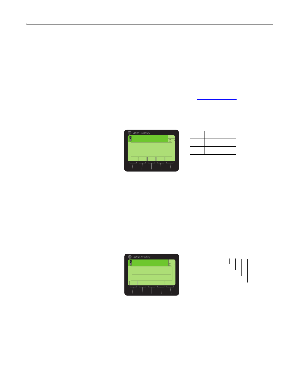
1. Display the Status screen, which is shown on HIM powerup.
2. Use the or key to scroll to the Port in which the embedded
EtherNet/IP adapter resides (always Port 13).
3. Press the PAR# soft key to display the Jump to Param # entry pop-up box.
4. Use the numeric keys to enter the desired parameter number, or use the
or soft key to scroll to the desired parameter number.
For details on viewing and editing parameters, see the PowerFlex 20-HIM-A6/C6S HIM (Human Interface Module) User Manual, publication 20HIM-
UM001.
When the adapter IP Address switches (Figure 1 on page 19) are set to a value
other than 001…254 or 888, Parameter 36 - [BOOTP] determines the source
for the adapter node address. By default, the embedded EtherNet/IP adapter is
configured to set its IP address, subnet mask, and gateway address by using a
BOOTP server. To use a BOOTP server to set the node address, see the
procedure in Using a BOOTP Ser ver
Adapter Parameters on page 30.
. To use adapter parameters, see Usin g
Using a BOOTP Server
If the PowerFlex 755 drive is connected to a Stratix 6000 or Stratix 8000
managed Ethernet switch and the drive is set for BOOTP mode, the ‘dynamic IP
address assignment by port’ (Stratix 6000) or ‘DHCP persistence’ (Stratix 8000)
feature will set the IP address for the drive. For more details, see the Stratix
6000 Ethernet Managed Switch User Manual, publication 1783-UM001
Stratix 8000 and Stratix 8300 Ethernet Managed Switches User Manual,
publication 1783-UM003
There is a variety of BOOTP servers available. The following instructions use
Rockwell Automation’s BOOTP/DHCP Server, version 2.3 or later, a free
standalone program that incorporates the functionality of standard BOOTP and
DHCP utilities with a graphical interface. It is available from http://
www.software.rockwell.com/support/download/detail.cfm?ID=3390. See the
Readme file and online Help for directions and more information.
If you prefer to configure the IP address, subnet mask, and gateway address
using adapter parameters, set adapter Parameter 36 - [BOOTP] to ‘0’
(disabled). For details, see Using Adapter Parameters
.
on page 30.
, or the
26 Rockwell Automation Publication 750COM-UM001E-EN-P - October 2013
Page 27
Configuring the Adapter Chapter 3
Value Setting
0Disabled
1Enabled (Default)
ESC
ENTER
Stopped
0.00 Hz
AUTO
F
▲▼
Edit BOOTP
Enabled 1
0<<1
Ethernet Address
(MAC) label location
Drive Control Pod
Ethernet
Conne ctor
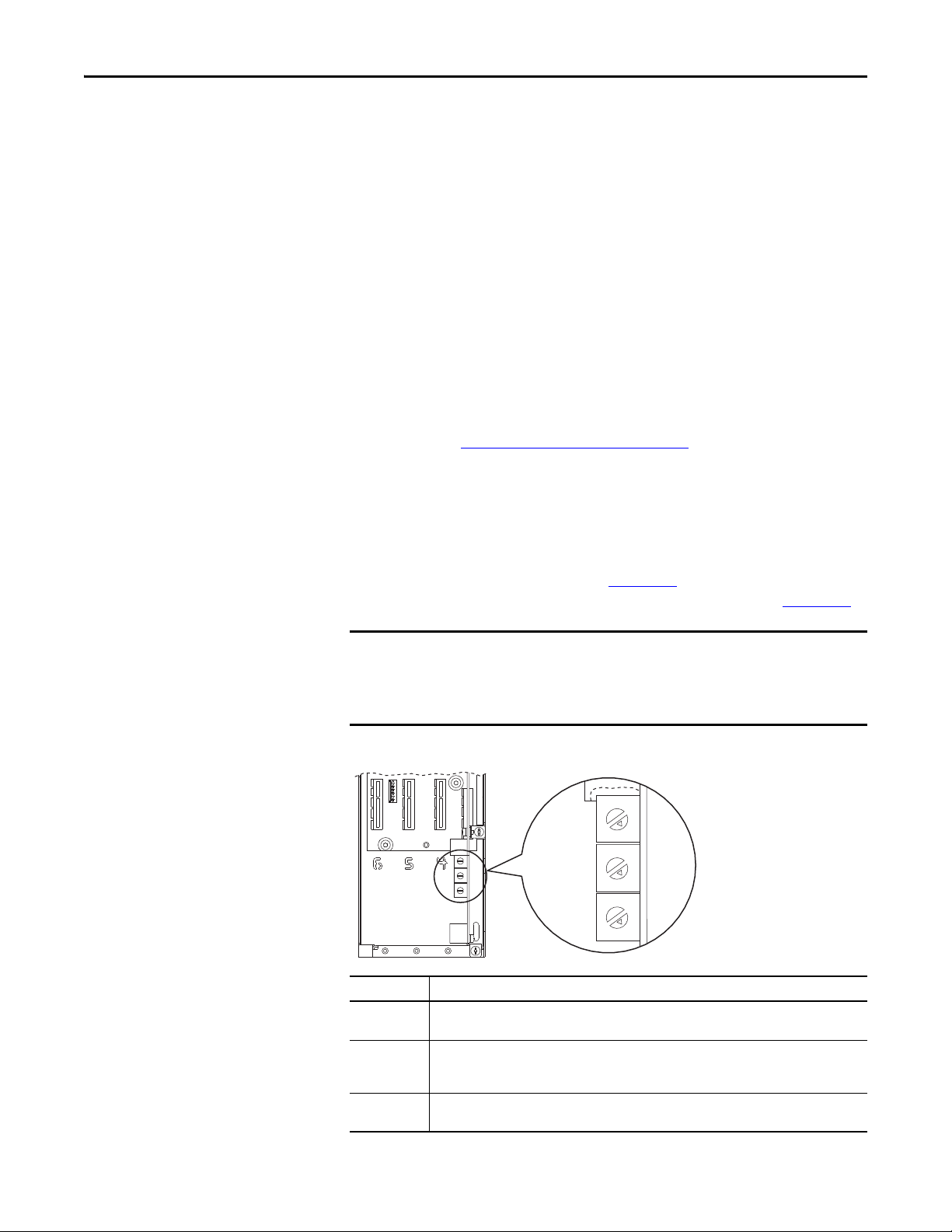
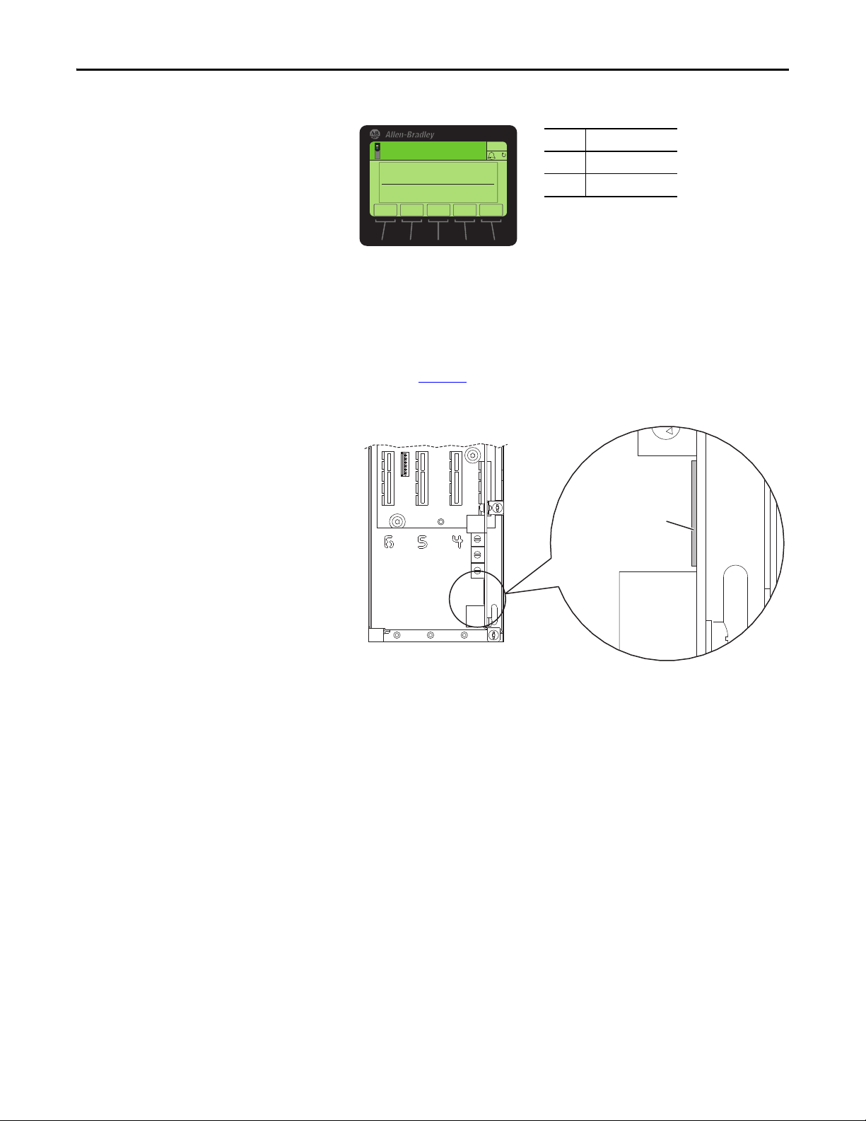
1. Ver if y t ha t Parameter 36 - [BOOTP] is set to ‘1’ (Enabled).
2. Note the adapter’s hardware Ethernet Address (MAC), which will be used
in step 7.
There are two ways to do this:
• Remove the PowerFlex 755 drive cover and locate the adapter’s
hardware Ethernet Address (MAC) label on the drive’s Main Control
Board (Figure 4
Figure 4 - Adapter Hardware Address Label Location
).
8
2
9
1
0
• Use the HIM to scroll to drive Port 13 and access the embedded
EtherNet/IP adapter DIAGNOSTIC folder screen. Then scroll to
Diagnostic Items 43…48 (HW Addr 1…6) to view the adapter’s
hardware Ethernet Address (MAC). Finally, convert these decimal
values to a hex value.
3. On a computer connected to the EtherNet/IP network, start the
BOOTP/DHCP software.
The BOOTP/DHCP Server dialog box appears.
Rockwell Automation Publication 750COM-UM001E-EN-P - October 2013 27
Page 28
Chapter 3 Configuring the Adapter
To properly configure devices on your EtherNet/IP network, you must
configure settings in the BOOTP/DHCP software to match the network.
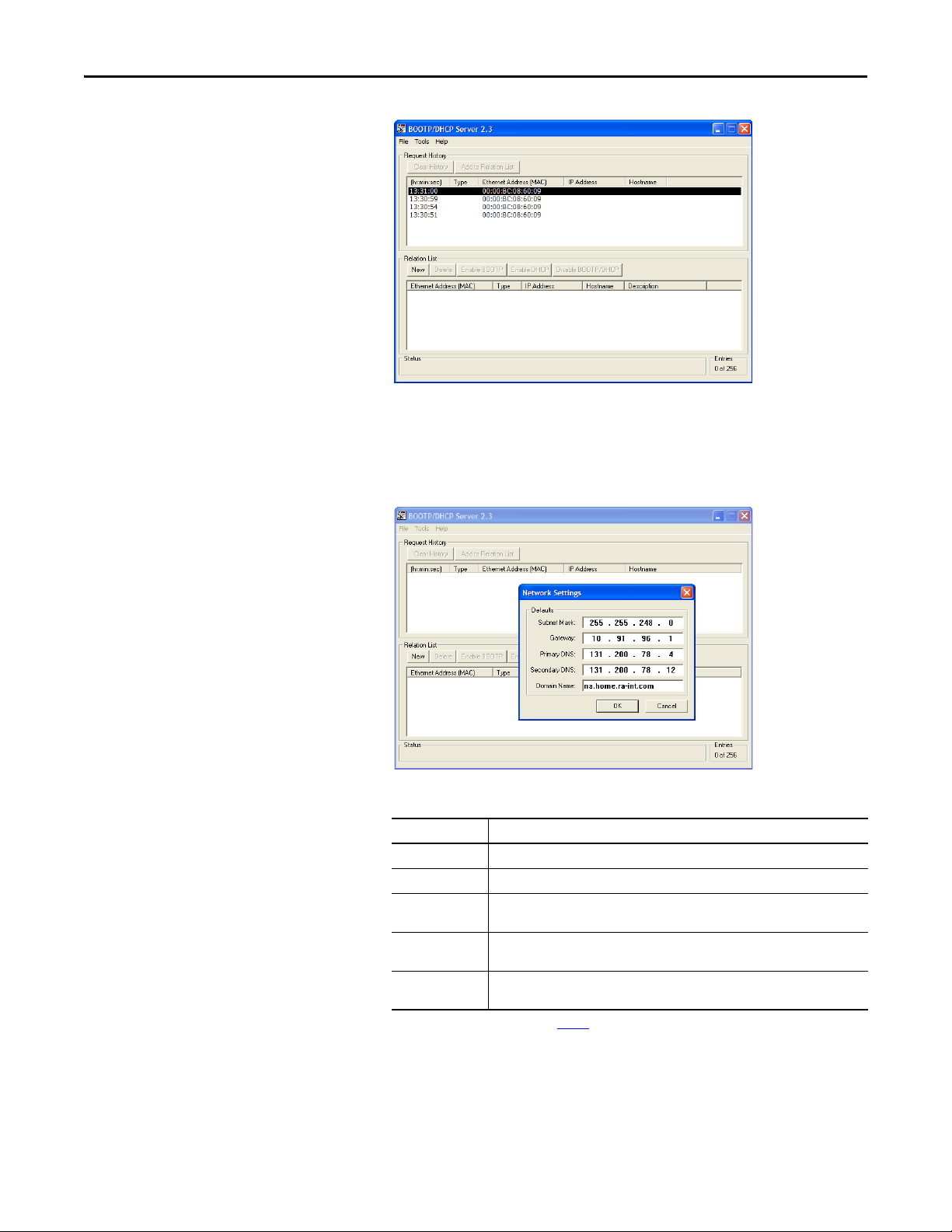
4. From the Tools menu, choose Network Settings.
The Network Settings dialog box opens.
5. Edit the following:
Box Type
Subnet Mask
Gateway
Primary DNS The address of the primary DNS server to be used on the local end of the link for
Secondary DNS Optional—the address of the secondary DNS server to be used on the local end of the
Domain Name The text name corresponding to the numeric IP address that was assigned to the server
(1) For definitions of these terms, see the Glossary.
(1)
The subnet mask for the embedded EtherNet/IP adapter’s network.
(1)
The IP address of the gateway device on the adapter’s network.
negotiating with remote devices.
link for negotiating with remote devices when the primary DNS server is unavailable.
that controls the network.
6. Click OK to apply the settings.
Devices on the network issuing BOOTP/DHCP requests appear in the
BOOTP/DHCP Request History list.
28 Rockwell Automation Publication 750COM-UM001E-EN-P - October 2013
Page 29
Configuring the Adapter Chapter 3
TIP
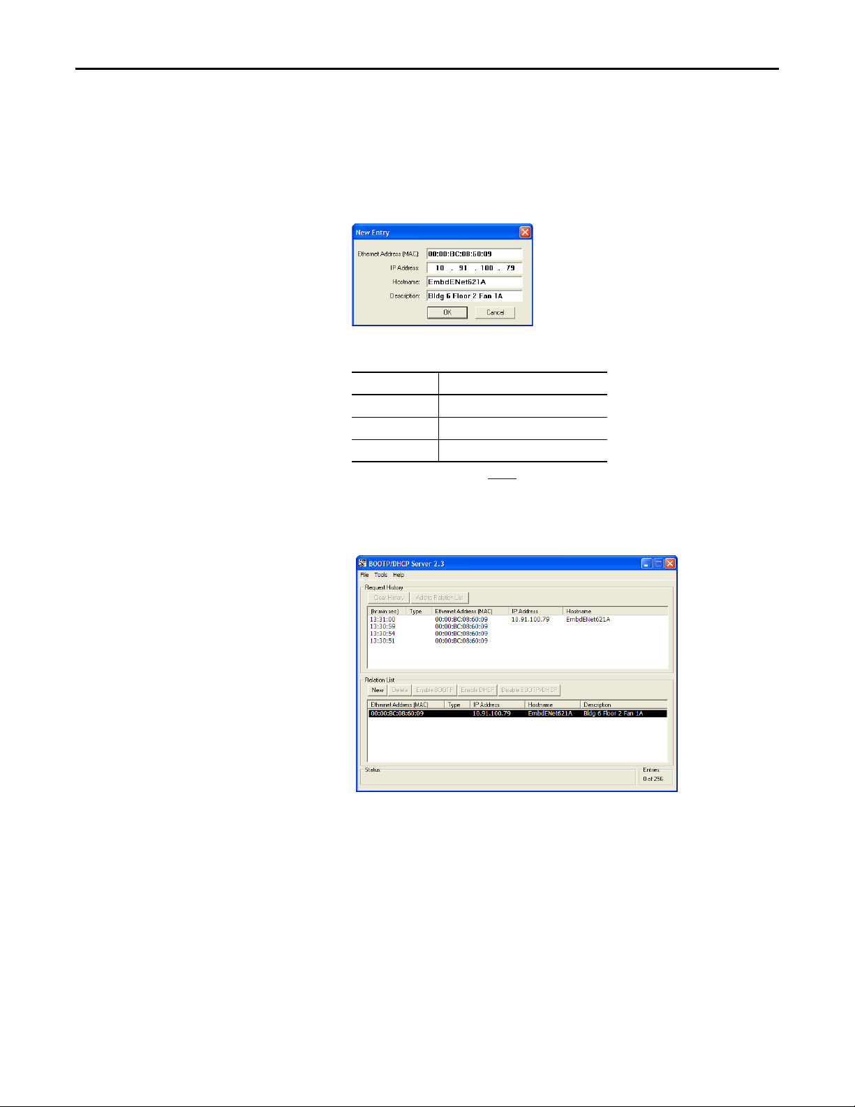
7. In the BOOTP/DHCP Request History list, either double-click the
adapter’s Ethernet Address (MAC) noted in step 2, or click New in the
Relation List.
The New Entry dialog box appears. In the first instance, the Ethernet
Address (MAC) is automatically entered. In the latter instance, it must be
manually entered.
8. Edit the following:
Box Type
(1)
IP Address
Host Name Optional
Description Optional
A unique IP address for the adapter
(1) For definition of this term, see the Glossary.
9. Click OK to apply the settings.
The adapter appears in the Relation List with the new settings.
10. To permanently assign this configuration to the adapter, select the device
in the Relation List and click Disable BOOTP/DHCP.
When power is cycled on the adapter, it will use the configuration you
assigned it and not issue new BOOTP requests.
To enable BOOTP for an embedded adapter that has had BOOTP
disabled, first select the adapter in the Relation List. Then click Enable
BOOTP and, lastly, reset the adapter or power cycle the drive.
11. From the File menu, choose Save to save the Relation List.
Rockwell Automation Publication 750COM-UM001E-EN-P - October 2013 29
Page 30
Chapter 3 Configuring the Adapter
Value Setting
0 Dis abled
1Enabled (Default)
ESC
ENTER
Stopped
0.00 Hz
AUTO
F
▲▼
Edit BOOTP
Disabled 0
0<<1
Default = 0.0.0.0 255.255.255.255
[IP Addr Cfg 1]
[IP Addr Cfg 2]
[IP Addr Cfg 3]
[IP Addr Cfg 4]
Edit IP Addr Cfg 1
0
0 << 255
ESC
ENTER
Stopped
0.00 Hz
AUTO
F
Using Adapter Parameters
By default, the adapter is configured to use a BOOTP server as the source for the
adapter IP address, subnet mask, and gateway address. To use adapter parameters
instead, you must first disable BOOTP with Parameter 36 - [BOOTP]. Then set
the associated adapter parameters as described in the following subsections.
Disable the BOOTP Feature
1. Verify that the IP Address switches (Figure 1 on page 19) are set to any
value other than 001…254 or 888.
The default setting is 999.
2. Set the value of Parameter 36 - [BOOTP] to ‘0’ (Disabled).
3. Reset the adapter by power cycling the drive or by using the HIM’s Reset
Device function located in the drive’s DIAGNOSTIC folder.
4. Perform the steps in the following subsections to set the IP address, subnet
mask, and gateway address using adapter parameters.
Set the IP Address
1. Ver if y t ha t Parameter 36 - [BOOTP] is set to ‘0’ (Disabled).
2. Set the value of Parameters 38 - [IP Addr Cfg 1] through 41 - [IP Addr
Cfg 4] to a unique IP address.
3. Reset the adapter by power cycling the drive or by using the HIM’s Reset
Device function located in the drive’s DIAGNOSTIC folder.
The ENET status indicator will be steady green or flashing green if the IP
address is correctly configured.
30 Rockwell Automation Publication 750COM-UM001E-EN-P - October 2013
Set the Subnet Mask
1. Ver if y t ha t Parameter 36 - [BOOTP] is set to ‘0’ (Disabled).
Page 31

Configuring the Adapter Chapter 3
Default = 0.0.0.0 255.255.255.255
[Subnet Cfg 1]
[Subnet Cfg 2]
[Subnet Cfg 3]
[Subnet Cfg 4]
Edit Subnet Cfg 1
0
0<<255
ESC
ENTER
Stopped
0.00 Hz
AUTO
F
Default = 0.0.0.0 255.255.255.255
[Gateway Cfg 1]
[Gateway Cfg 2]
[Gateway Cfg 3]
[Gateway Cfg 4]
Edit Gateway Cfg 1
0
0 << 255
ESC
ENTER
Stopped
0.00 Hz
AUTO
F
Value Data Rate
0 Autodetect (default)
1 10 Mbps Full
2 10 Mbps Half
3 100 Mbps Full
4 100 Mbps Half
ESC
ENTER
Stopped
0.00 Hz
AUTO
F
▲▼
Edit Net Rate Cfg
Autodetect 0
0<<4
2. Set the value of Parameters 42 - [Subnet Cfg 1] through 45 - [Subnet
Cfg 4] to the desired value for the subnet mask.
3. Reset the adapter by power cycling the drive or by using the HIM’s Reset
Device function located in the drive’s DIAGNOSTIC folder.
Set the Gateway Address
1. Ver if y t ha t Parameter 36 - [BOOTP] is set to ‘0’ (Disabled).
2. Set the value of Parameters 46 - [Gateway Cfg 1] through 49 - [Gateway
Cfg 4] to the IP address of the gateway device.
Setting the Data Rate
3. Reset the adapter by power cycling the drive or by using the HIM’s Reset
Device function located in the drive’s DIAGNOSTIC folder.
By default, the adapter is set to autodetect, so it automatically detects the data
rate and duplex setting used on the network. If you need to set a specific data rate
and duplex setting, the value of Parameter 50 - [Net Rate Cfg] determines the
Ethernet data rate and duplex setting that the adapter will use to communicate.
For definitions of data rate and duplex, see the Glossary
1. Set the value of Parameter 50 - [Net Rate Cfg] to the data rate at which
your network is operating.
.
Rockwell Automation Publication 750COM-UM001E-EN-P - October 2013 31
Page 32

Chapter 3 Configuring the Adapter
TIP
IMPORTANT
TIP
Auto detection of baud rate and duplex works properly only if the
device (usually a switch) on the other end of the cable is also set to
automatically detect the baud rate/duplex. If one device has the baud
rate/duplex hard-coded, the other device must be hard-coded to the
same settings.
2. Reset the adapter by power cycling the drive or by using the HIM’s Reset
Device function located in the drive’s DIAGNOSTIC folder.
Selecting Master-Slave or Peer-to-Peer Hierarchy
This procedure is only required if Datalinks are used to write or read data of the
drive or its connected peripherals. A hierarchy determines the type of device with
which the adapter exchanges data. In a Master-Slave hierarchy, the adapter
exchanges data with a master, such as a scanner or bridge. In a Peer-to-Peer
hierarchy, the adapter exchanges data with embedded EtherNet/IP adapters in
other PowerFlex 755 drives.
For both Master-Slave and Peer-to-Peer hierarchies, the devices exchanging data
must be on the same IP subnet. See ‘IP Addresses’ in the Glossary
about IP subnets.
Setting a Master-Slave Hierarchy
Enable Datalinks To Write Data
The controller output image (controller outputs-to-drive) can have 0 to 16
additional 32-bit parameters (Datalinks). They are configured using Parameters
01 - [DL From Net 01] through 16 - [DL From Net 16]. The number of
Datalinks actively used is controlled by the connection size in the controller. See
the respective controller example sections in Chapter 4
setting the connection size.
for more information on
for information
Always use the Datalink parameters in consecutive numerical order, starting
with the first parameter. For example, use Parameters 01, 02, and 03 to
configure three Datalinks to write data. Otherwise, the network I/O connection
When using a ControlLogix controller and the Generic Profile, configure the
Datalink parameters now as described in this section.
Parameters 01 - [DL From Net 01] through 16 - [DL From Net 16] control
32 Rockwell Automation Publication 750COM-UM001E-EN-P - October 2013
which parameters in the drive, embedded adapter, or any other connected
will be larger than necessary, which needlessly increases controller response
time and memory usage.
When using a ControlLogix controller and an RSLogix 5000 drive Add-on
Profile, version 16.00 or later, there is no need to configure Datalink
parameters at this time. They will be assigned when configuring the RSLogix
5000 drive Add-on Profile (see Add the Drive/Adapter to the I/O Configuration
on page 50).
Page 33

Configuring the Adapter Chapter 3
peripheral receive the values from the network. You can use the PowerFlex 20HIM-A6 or 20-HIM-C6S HIM, or another drive configuration tool such as
Connected Components Workbench, DriveExplorer, or DriveExecutive software
to select the drive or peripheral by port number and the parameter by name. As
an alternate method, the parameter value can be set manually by number using
this formula:
From Net Parameter Value = (10000 * Port Number) + (Destination Parameter Number)
For example, suppose you want to use Parameter 01 - [DL From Net 01] to
write to Parameter 03 of an optional encoder card plugged into drive Port 5.
Using the formula, the value for Parameter 01 - [DL From Net 01] would be
(10000 * 5) + (3) = 50003.
Follow these steps to enable Datalinks to write data.
1. Set the values of only the required number of contiguous controller-todrive Datalinks needed to write data to the drive and that are to be
included in the network I/O connection.
2. Reset the adapter by power cycling the drive or by using the HIM’s Reset
Device function located in the drive’s DIAGNOSTIC folder.
3. Since the Logic Command and Reference are always used in the adapter,
configure the parameters in the drive to accept the Logic Command and
Reference from the adapter.
When using the controller for speed reference via the adapter, set two
fields in drive Parameter 545 - [Speed Ref A Sel].
a. Set the Port field for the drive (for example, 0 - PowerFlex 755).
b. Set the Parameter field to point to the drive port in which the
embedded EtherNet/IP adapter is installed (always ‘Port 13 Reference’,
the drive port dedicated to the embedded adapter).
Also, verify that the mask parameters in the drive (for example,
Parameter 324 - [Logic Mask]) are configured to receive the desired
logic from the adapter. See the drive documentation for details.
After the above steps are complete, the adapter is ready to receive input data and
transfer status data to the master (controller). Next, configure the controller to
recognize and transmit I/O to the adapter. See Chapter 4
Enable Datalinks To Read Data
The controller input image (drive-to-controller inputs) can have 0 to 16
additional 32-bit parameters (Datalinks). They are configured using Parameters
17 - [DL To Net 01] through 32 - [DL To Net 16]. The number of Datalinks
actively used is controlled by the connection size in the controller. See the
, Configuring the I/O.
Rockwell Automation Publication 750COM-UM001E-EN-P - October 2013 33
Page 34

Chapter 3 Configuring the Adapter
IMPORTANT
TIP
respective controller example sections in Chapter 4 for more information on
setting the connection size.
Always use the Datalink parameters in consecutive numerical order, starting
with the first parameter. For example, use Parameters 17, 18, 19, 20, and 21 to
configure five Datalinks to read data. Otherwise, the network I/O connection
will be larger than necessary, which needlessly increases controller response
time and memory usage.
When using a ControlLogix controller and an RSLogix 5000 drive Add-on
Profile, version 16.00 or later, there is no need to configure Datalink
parameters at this time. They will be assigned when configuring the RSLogix
5000 drive Add-on Profile (see Add the Drive/Adapter to the I/O Configuration
on page 50).
When using a ControlLogix controller and the Generic Profile, configure the
Datalink parameters now as described in this section.
Parameters 17 - [DL To Net 01] through 32 - [DL To Net 16] configure which
parameters in the drive, adapter, or any other connected peripheral send the
values to the network. You can use the PowerFlex 20-HIM-A6 or 20-HIM-C6S
HIM, or another drive configuration tool such as Connected Components
Workbench, DriveExplorer, or DriveExecutive software to select the drive or
peripheral by port number and the parameter by name. As an alternate method,
the parameter value can be set manually by number using this formula:
To Net Parameter Value = (10000 * Port Number) + (Origination Parameter Number)
For example, suppose you want to use Parameter 17 - [DL To Net 01] to read
Parameter 2 of an optional I/O card plugged into drive Port 6. Using the formula,
the value for Parameter 17 - [DL To Net 01] would be (10000 * 6) + (2) = 60002.
Follow these steps to enable Datalinks to read data.
1. Set the values of only the required number of contiguous drive-tocontroller Datalinks needed to read data from the drive and that are to be
included in the network I/O connection.
2. Reset the adapter by power cycling the drive or by using the HIM’s Reset
Device function located in the drive’s DIAGNOSTIC folder.
The adapter is configured to send output data to the master (controller). You
must now configure the controller to recognize and transmit I/O to the adapter.
See Chapter 4
Setting the Adapter to Transmit Peer-to-Peer Data
Peer-to-peer communication can be set up as a simple peer I/O configuration or a
custom peer I/O configuration.
, Configuring the I/O.
34 Rockwell Automation Publication 750COM-UM001E-EN-P - October 2013
Page 35

Configuring the Adapter Chapter 3
IMPORTANT
Value Setting
0Off (Default)
1Cmd/Ref
2Custom
ESC
ENTER
Stopped
0.00 Hz
AUTO
F
▲▼
Edit To Peer Enable
Off 0
0<<2
Simple Peer I/O Configuration
The most common use of peer I/O is to take the Logic Command and Reference
from one drive and repeat it over Ethernet to one or more other drives. If scaling
of the Reference is needed to enable drives to run at different but related speeds,
use drive Parameter 609 - [TrmPct RefA Stpt]. The embedded EtherNet/IP
adapter provides a simplified configuration method for simple peer I/O.
Because of the 32-bit REAL (floating point) Reference, the following method
works only if the drives transmitting and receiving are PowerFlex 750-Series
drives. Peer-to-peer communication only works between drives with a 20-750ENETR option module or PowerFlex 755 drives with the embedded EtherNet/IP
adapter.
Follow these steps to set up the master (broadcast) side of simple peer I/O.
1. Set Parameters 89 - [To Peer Period] and 90 - [To Peer Skip] as desired
for your application.
Parameter 89 controls how frequently the adapter will transmit data when
it is changing. Parameter 90 controls how frequently the adapter will
transmit data when it is not changing.
2. Set Parameter 91 - [To Peer Enable] to a value of ‘1’ (Cmd/Ref).
Follow these steps to set up the slave (receiver) side of simple peer I/O.
1. Set Parameter 80 - [Fr Peer Timeout] to a suitable timeout value for your
application.
This value should be greater than the product of Parameter 89 - [To Peer
Period ] and Parameter 90 - [To Peer Skip] in the transmitting drive.
2. Set Parameters 81 - [Fr Peer Addr 1] through 84 - [Fr Peer Addr 4] to
the IP address of the drive transmitting peer I/O.
3. In each PowerFlex 750-Series slave drive, set drive parameter 308 [Direction Mode] to ‘0’ (Unipolar) to ensure that it properly follows the
master drive’s speed reference and commanded direction.
4. Set Parameter 85 - [Fr Peer Enable] to a value of ‘1’ (Cmd/Ref).
Rockwell Automation Publication 750COM-UM001E-EN-P - October 2013 35
Page 36

Chapter 3 Configuring the Adapter
IMPORTANT
Custom Peer I/O Configuration
Peer I/O also allows more flexibility in sending custom data over the network,
but requires more configuration.
Because of the 32-bit REAL (floating point) Reference, the following method
works only if the drives transmitting and receiving are PowerFlex 750-Series
drives.
Follow these steps to set up the master (broadcast) side of custom peer I/O.
1. Decide how many Datalink parameters you want to transmit. Set
Parameter 87 - [DLs To Peer Cfg] to that value.
2. Determine how the Datalinks are allocated.
The highest numbered of the 16 Datalinks are allocated to peer I/O. For
example, if Parameter 87 - [DLs To Peer Cfg] is set to ‘3’, then Datalinks
14, 15, and 16 are allocated to peer I/O. To avoid an overlap between
Master-Slave and peer I/O, make sure that Parameter 35 - [DLs To Net
Act] plus Parameter 87 - [DLs To Peer Cfg] does not total more than 16.
3. Set Parameters 17 through 32 - [DL To Net 01-16] to the parameters you
want to transmit, based on the allocation in step 2.
4. Reset the adapter by power cycling the drive or by using the HIM’s Reset
Device function located in the drive’s DIAGNOSTIC folder so that
changes to Parameter 87 - [DLs To Peer Cfg] take effect.
5. Set Parameters 89 - [To Peer Period] and 90 - [To Peer Skip] as required
for your application.
Parameter 89 controls how frequently the adapter will transmit data when
it is changing. Parameter 90 controls how frequently the adapter will
transmit data when it is not changing.
6. Set Parameter 91 - [To Peer Enable] to a value of ‘2’ (Custom).
Follow these steps to set up the slave (receiver) side of custom peer I/O.
1. Decide how many pieces of data (Logic Command, Reference, and
Datalink parameters) you want to receive and set Parameter 76 - [DLs Fr
Peer Cfg] to that value.
This must match the number of parameters transmitted by the master.
2. Determine how the Datalinks are allocated.
The highest numbered of the 16 Datalinks are allocated to peer I/O. For
example, if Parameter 76 - [DLs Fr Peer Cfg] is set to ‘3’, Datalinks 14,
15, and 16 are allocated to peer I/O. To avoid an overlap between MasterSlave and peer I/O, make sure that Parameter 34 - [DLs From Net Act]
plus Parameter 76 - [DLs Fr Peer Cfg] does not total more than 16.
3. Set Parameters 1 through 16 - [DL From Net 01-16] to the parameters
you want to receive, based on the allocation in step 2.
36 Rockwell Automation Publication 750COM-UM001E-EN-P - October 2013
Page 37

Edit Fr Peer Timeout
10.00 Secs
0.01 << 10.00
ESC
.
ENTER
Stopped
0.00 Hz
AUTO
F
Value Description
0 Fault (Default)
1Stop
2Zero Data
3 Hold Last
4Send Flt Cfg
ESC
ENTER
Stopped
0.00 Hz
AUTO
F
▲▼
Edit Peer Flt Action
Fault 0
0<<4
Default = 0.0.0.0
255.255.255.255
[Peer Inp Addr 1]
[Peer Inp Addr 2]
[Peer Inp Addr 3]
[Peer Inp Addr 4]
IP Address of Node Transmitting Custom Peer I/O
Edit Fr Peer Addr 1
0
0 << 255
ESC
ENTER
Stopped
0.00 Hz
AUTO
F
Configuring the Adapter Chapter 3
4. Set Parameter 80 - [Fr Peer Timeout] to a timeout value for your
application.
This value should be greater than the product of Parameter 89 - [To Peer
Period ] and Parameter 90 - [To Peer Skip] in the transmitting drive.
5. Set Parameter 56 - [Peer Flt Action] to the desired action if peer I/O data
is not received before the timeout is reached.
ATTENTION: Risk of injury or equipment damage exists. Parameter 56 - [Peer
Flt Action] lets you determine the action of the adapter and connected drive if
the adapter is unable to communicate with the designated peer. By default, this
parameter faults the drive. You may configure this parameter so that the drive
continues to run, however, precautions should be taken to verify that the setting
of this parameter does not create a hazard of injury or equipment damage. When
commissioning the drive, verify that your system responds correctly to various
situations (for example, a disconnected cable).
For more details about fault action, see Setting a Fault Action on page 38.
6. Set Parameters 81 - [Fr Peer Addr 1] through 84 - [Fr Peer Addr 4] to
Rockwell Automation Publication 750COM-UM001E-EN-P - October 2013 37
the IP address of the drive transmitting the custom peer I/O.
7. If a Logic Command is being sent, use Parameter 78 - [Logic Src Cfg] to
set the number of the Datalink that contains the Logic Command within
the range defined by Parameter 76 - [DLs Fr Peer Cfg].
Page 38

Chapter 3 Configuring the Adapter
Value S etting
0 Off (Default)
1Cmd/Ref
2Custom
ESC
ENTER
Stopped
0.00 Hz
AUTO
F
▲▼
Edit Fr Peer Enable
Off 0
0<<2
For example, if Parameter 76 - [DLs Fr Peer Cfg] is set to receive five
Datalinks (Datalinks 12 through 16) and the first of those five Datalinks
(Datalink 12) contains the Logic Command, set Parameter 78 - [Logic
Src Cfg] to a value of ‘1’. Otherwise, set Parameter 78 to a value of ‘0’. For
Logic Command bit definitions, see Appendix
documentation.
8. If a Reference is being sent, use Parameter 79 - [Ref Src Cfg] to set the
number of the Datalink that contains the Reference within the range
defined by Parameter 76 - [DLs Fr Peer Cfg].
For example, if Parameter 76 - [DLs Fr Peer Cfg] is set to receive five
Datalinks (Datalinks 12 through 16) and the second of those five
Datalinks (Datalink 13) contains the Reference, set Parameter 79 - [Ref
Src Cfg] to a value of ‘2’. Otherwise, set Parameter 79 to a value of ‘0’.
9. In each PowerFlex 750-Series slave drive, set drive parameter 308 -
[Direction Mode] to ‘0’ (Unipolar) to be sure that it properly follows the
master drive’s speed reference and commanded direction.
10. Reset the adapter by power cycling the drive or by using the HIM’s Reset
Device function located in the drive’s DIAGNOSTIC folder so that
changes to Parameter 76 - [DLs Fr Peer Cfg] take effect.
D or the drive
Setting a Fault Action
11. Set Parameter 85 - [Fr Peer Enable] to a value of ‘2’ (Custom).
By default, when communication is disrupted (for example, the network cable is
disconnected), the controller is idle (in program mode or faulted), and/or peer
I/O or explicit messaging for drive control is disrupted, the drive responds by
faulting if it is using I/O from the network. You can configure a different
response to these faults:
• Disrupted I/O communication by using Parameter 54 - [Comm Flt Action].
• An idle controller by using Parameter 55 - [Idle Flt Action].
• Disrupted peer I/O by using Parameter 56 - [Peer Flt Action].
• Disrupted explicit messaging for drive control via PCCC, the CIP
Register Object or the CIP Assembly Object by using Parameter 57 [Msg Flt Action].
38 Rockwell Automation Publication 750COM-UM001E-EN-P - October 2013
Page 39

Configuring the Adapter Chapter 3
ESC
ENTER
Stopped
0.00 Hz
AUTO
F
▲▼
Edit Comm Flt Action
Fault 0
0<<4
ESC
ENTER
Stopped
0.00 Hz
AUTO
F
▲▼
Edit Idle Flt Action
Fault 0
0<<4
ESC
ENTER
Stopped
0.00 Hz
AUTO
F
▲▼
Edit Msg Flt Action
Fault 0
0<<4
ESC
ENTER
Stopped
0.00 Hz
AUTO
F
▲▼
Edit Peer Flt Action
Fault 0
0<<4
ATTENTION: Risk of injury or equipment damage exists. Embedded adapter
Parameters 54 - [Comm Flt Action], 55 - [Idle Flt Action], 56 - [Peer Flt
Action], and 57 - [Msg Flt Action] respectively let you determine the action of
the adapter and drive if communication is disrupted, the controller is idle, peer
I/O is disrupted, or explicit messaging for drive control is disrupted. By default,
these parameters fault the drive. You may configure these parameters so that the
drive continues to run, however, precautions should be taken to verify that the
settings of these parameters do not create a risk of injury or equipment damage.
When commissioning the drive, verify that your system responds correctly to
various situations (for example, a disconnected network cable, controller in idle
state or explicit message control disruption).
Changing the Fault Action
Set the values of Parameters 54 - [Comm Flt Action], 55 - [Idle Flt Action], 56
- [Peer Flt Action], and 57 - [Msg Flt Action] to an action that meets your
application requirements.
Value Action Description
0 Fault The drive is faulted and stopped. (Default)
1 Stop The drive is stopped, but not faulted.
2 Zero Data The drive is sent ‘0’ values for data. This does not command a stop.
3 Hold Last The drive continues in its present state.
4 Send Flt Cfg The drive is sent the data that you set in the fault configuration parameters (Parameters 58
- [Flt Cfg Logic], 59 - [Flt Cfg Ref], and 60 - [Flt Cfg DL 01] through 75 - [F lt Cfg DL 16]).
Figure 5 - Edit Fault Action HIM Screens
Changes to these parameters take effect immediately. A reset is not required.
If communication is disrupted and then re-established, the drive will
automatically receive commands over the network again.
Setting the Fault Configuration Parameters
When setting Parameter 54 - [Comm Flt Action], 55 - [Idle Flt Action], 56 [Peer Flt Action] or Parameter 57 - [Msg Flt Action] to ‘Send Flt Cfg’, the
values in the following parameters are sent to the drive after a communication
fault, idle fault, peer I/O fault, and/or explicit messaging for drive control fault
Rockwell Automation Publication 750COM-UM001E-EN-P - October 2013 39
Page 40

Chapter 3 Configuring the Adapter
Value Description
0 Disabled (Default)
1Enabled
ESC
ENTER
Stopped
0.00 Hz
AUTO
F
▲▼
Edit Web Enable
Disabled 0
0<<1
Bit Description
0 E-mail Cfg (Default = 1 = Enabled)
1…15 Not Used
ES C ENTER
Stopped
0.00 Hz
AUTO
F
Edit Web Features
xxxx xxxx xxxx xxx1
E-mail Cfg
occurs. You must set these parameters to values required by your application.
Adapter Parameter Description
Parameter 58 - [Flt Cfg Logic] A 32-bit value sent to the drive for Logic Command.
Parameter 59 - [Flt Cfg Ref] A 32-bit REAL (floating point) value sent to the drive for Reference.
Parameter 60 - [Flt Cfg DL 01]
through
Parameter 75 - [Flt Cfg DL 16]
Changes to these parameters take effect immediately. A reset is not required.
A 32-bit integer value sent to the drive for a Datalink. If the destination of the
Datalink is a REAL (floating point) parameter, you must convert the desired value to
the binary representation of the REAL value. (An internet search of ‘hex to float’
provides a link to a tool to do this conversion.)
Setting Web Access Control
By using a web browser to access the IP address set for the adapter, you can view
the adapter web pages for information about the adapter, the drive, and other
DPI devices connected to the drive, such as HIMs or converters.
By default, the adapter web pages are disabled. To enable the adapter web pages,
set Parameter 52 - [Web Enable] to ‘1’ (Enabled) and then reset the adapter for
the change to take effect.
For more details on the adapter’s web pages, see Chapter 8
Web Pa g es .
The adapter can be configured to automatically send e-mail messages to desired
addresses when selected drive faults occur and/or are cleared, and/or when the
adapter takes a communication or idle fault action.
, Viewing the Adapter
40 Rockwell Automation Publication 750COM-UM001E-EN-P - October 2013
Bit 0 of Parameter 53 - [ Web Features] is used to protect the configured settings
for e-mail messaging. By default, settings are not protected and the user can make
changes. To protect the configured settings, set the value of E-mail Cfg Bit 0 to ‘0’
(Disabled). You can unprotect the configuration by changing Bit 0 back to ‘1’
(Enabled). E-mail messaging will always remain active regardless of whether or
not its settings are protected—unless e-mail messaging was never configured. For
more information about configuring adapter e-mail messaging or to stop e-mail
messages, see Configure E-mail Notification Web Page
on page 118.
Page 41

Configuring the Adapter Chapter 3
Stopped
0.00 Hz
AUTO
Host Drive
240V 4.2A
Rev 3.002 Ser. A
ESC REF TEXT
F
PAR#
Bit 0 is the right-most bit. In the example above, it equals ‘1’ (Enabled).
Changes to this parameter take effect immediately. A reset is not required.
Resetting the Adapter
Restoring Adapter Parameters to Factory Defaults
Changes to switch settings and some adapter parameters require that you reset
the adapter before the new settings take effect. You can reset the adapter by
cycling power to the drive or by using the HIM’s Reset Device function located in
the drive’s DIAGNOSTIC folder.
ATTENTION: Risk of injury or equipment damage exists. If the adapter is
transmitting control I/O to the drive, the drive may fault when you reset the
adapter. Determine how your drive will respond before resetting the adapter.
Adapter parameters can be restored in two ways:
• ALL—restores ALL adapter parameters to their factory default values.
• MOST—restores MOST adapter parameters—except the following
which are used for network setup:
– Parameter 36 - [BOOTP]
– Parameters 38…41 - [IP Addr Cfg 1-4]
– Parameters 42…45 - [Subnet Cfg 1-4]
– Parameters 46…49 - [Gateway Cfg 1-4]
– Parameter 50 - [Net Rate Cfg]
Follow these steps to restore adapter parameters to their factory default values.
1. Access the Status screen, which is displayed on HIM powerup.
00
2. Use the or key to scroll to Port 13, which is always the drive
port dedicated to the embedded EtherNet/IP adapter.
3. Press the key to display its last-viewed folder.
4. Use the or key to scroll to the MEMORY folder.
5. Use the or key to select Set Defaults.
6. Press the (Enter) key to display the Set Defaults pop-up box.
Rockwell Automation Publication 750COM-UM001E-EN-P - October 2013 41
Page 42

Chapter 3 Configuring the Adapter
IMPORTANT
7. Press the (Enter) key again to display the warning pop-up box to
reset parameters to their factory default values.
8. Press the MOST soft key to restore MOST parameters to factory defaults,
or press the ALL soft key to restore ALL parameters. Or press the
key to cancel.
When performing a Set Defaults, the drive may detect a conflict and
then not allow this function to occur. If this happens, first resolve the
conflict and then repeat this Set Defaults procedure. Common reasons
for a conflict include the drive running or a controller in Run mode.
9. Reset the adapter by cycling power to the drive or by using the HIM’s
Reset Device function located in the drive’s DIAGNOSTIC folder.
ESC soft
Viewing the Adapter Status Using Parameters
The following parameters provide information about the status of the adapter.
You can view these parameters at any time.
Adapter Parameter Description
34 - [DLs From Net Act] The number of controller-to-drive Datalinks that are included in the network I/O
35 - [DLs To Net Act] The number of drive-to-controller Datalinks that are included in the network I/O
37 - [Net Addr Src] Displays the source from which the adapter IP address is taken. The source is determined
50 - [Net Rate Act] The data rate used by the adapter.
86 - [Fr Peer Status] The status of the consumed peer I/O input connection, which can be one of the following
77 - [DLs Fr Peer Act] The number of peer-to- drive Datalinks that the drive is expecting.
88 - [DLs To Peer Act] The number of drive-to-peer Datalinks that the drive is expecting.
connection (controller outputs).
connection (controller inputs).
by the IP address switch settings shown in Figure 1
[BOOTP] is enabled or disabled. The source can be one of the following:
• ‘0’ (Switches)
• ‘1’ (Parameters)—uses the address from Parameters 38…41 [IP Addr Cfg x]
• ‘2’ (BOOTP)—the default
values:
0 = Off
1 = Waiting
2 = Running
3 = Faulted
, and whether Parameter 36 -
42 Rockwell Automation Publication 750COM-UM001E-EN-P - October 2013
Page 43

Configuring the Adapter Chapter 3
Updating the Adapter Firmware
The adapter firmware is contained within the PowerFlex 755 drive firmware. The
adapter firmware can be updated over the network or serially through a direct
connection from a computer to the drive using a 1203-USB or 1203-SSS serial
converter.
When updating firmware over the network, you can use the Allen-Bradley
ControlFLASH software tool, the built-in update capability of DriveExplorer
Lite or Full software, or the built-in update capability DriveExecutive software.
When updating firmware through a direct serial connection from a computer to a
drive, you can use the same Allen-Bradley software tools described above, or you
can use HyperTerminal software set to the X-modem protocol.
To obtain a firmware update for this adapter, go to http://www.ab.com/support/
abdrives/webupdate. This website contains all firmware update files and
associated Release Notes that describe the following items:
• Firmware update enhancements and anomalies
• How to determine the existing firmware revision
• How to update the firmware using ControlFLASH, DriveExplorer,
DriveExecutive, or HyperTerminal software
Rockwell Automation Publication 750COM-UM001E-EN-P - October 2013 43
Page 44

Chapter 3 Configuring the Adapter
Notes:
44 Rockwell Automation Publication 750COM-UM001E-EN-P - October 2013
Page 45

Chapter 4
Configuring the I/O
This chapter provides instructions on how to configure a Rockwell Automation
ControlLogix controller to communicate with the adapter and connected
PowerFlex drive.
For information on using a PLC-5, SLC 500, or MicroLogix 1100/1400
controller, see Controller Examples for EtherNet/IP Network Communications
with PowerFlex 750-Series Drives, publication 750COM-AT001
Top ic Pa ge
Using RSLinx Classic 45
ControlLogix Example 46
.
Using RSLinx Classic
RSLinx Classic software, in all its variations (Lite, Gateway, OEM, and so forth), is
used to provide a communication link between the computer, network, and
controller. RSLinx Classic software requires its network-specific driver to be
configured before communication is established with network devices. To
configure the RSLinx driver, follow this procedure.
1. Start RSLinx Classic software.
2. From the Communications menu, choose Configure Drivers to display the
Configure Drivers dialog box.
3. From the Available Driver Types pull-down menu, choose EtherNet/IP
Driver.
4. Click Add New to display the Add New RSLinx Driver dialog box.
5. Use the default name or type a name.
6. Click OK.
The ‘Configure driver:’ dialog box appears.
7. Depending on your application, select either the browse local or remote
subnet option.
8. Click OK.
Rockwell Automation Publication 750COM-UM001E-EN-P - October 2013 45
Page 46

Chapter 4 Configuring the I/O
TIP
The Configure Drivers dialog box reappears with the new driver in the
Configured Drivers list.
9. Click Close to close the Configure Drivers dialog box.
10. Keep RSLinx software running and verify that your computer recognizes
the drive.
a. From the Communications menu, choose RSWho.
b. In the menu tree, click the ‘+’ next to the Ethernet driver.
ControlLogix Example
If the ‘EtherNet/IP Driver’ cannot see your drive, as an alternative, use
either the ‘Ethernet devices’ or ‘Remote Devices via Linx Gateway’ RSLinx
driver.
The example in this section is for a Master-Slave hierarchy. The ControlLogix
controller, firmware revision 19.00 or later, and the PowerFlex 755 drive,
firmware 2.003 or later, also support ‘Integrated Motion on the EtherNet/IP
network’ operation. For details to set up ‘Integrated Motion on the EtherNet/IP
network’ operation, see Integrated Motion on the EtherNet/IP Network,
publication MOTION-UM003
For best reliability in ‘Integrated Motion on the EtherNet/IP network’
applications, we recommend that you always use Rockwell Automation Cat5e
shielded Ethernet cable.
Example Network
After the adapter is configured, the drive and adapter will be a single node on the
network. This section provides the steps needed to configure a simple EtherNet/
IP network (see Figure 6
(Series A) bridge to communicate with a drive using Logic Command/Status,
Reference/Feedback, and 32 Datalinks (16 to read and 16 to write) over the
network.
). In our example, we will configure a 1756-ENBT
.
46 Rockwell Automation Publication 750COM-UM001E-EN-P - October 2013
Page 47

Configuring the I/O Chapter 4
IP Address 10.91.100.80
ControlLogix Controlle r with
1756-ENBT Bridge
IP Address 10.91.100.79
PowerFlex 755 Drive with
Embedded EtherNet/IP Adapter
Computer with
Ethernet Connection
Ethernet
Switch
Figure 6 - Example ControlLogix Controller EtherNet/IP Network
Adding the Bridge to the I/O Configuration
To establish communications between the controller and adapter over the
network, you must first add the ControlLogix controller and its bridge to the
I/O configuration.
1. Start RSLogix 5000 software.
2. From the File menu, choose New to display the New Controller dialog
3. In the treeview, right-click the I/O Configuration folder and choose New
box.
a. Choose the appropriate choices for the fields in the dialog box to match
your application.
b. Click OK.
The RSLogix 5000 dialog box reappears with the treeview in the left
pane.
Module.
The Select Module dialog box appears.
Rockwell Automation Publication 750COM-UM001E-EN-P - October 2013 47
Page 48

Chapter 4 Configuring the I/O
4. Expand the Communications group to display all of the available
communication modules.
5. In the list, select the EtherNet/IP bridge used by your controller.
In this example, we use a 1756-ENBT EtherNet/IP Bridge (Series A), so
the 1756-ENBT/A option is selected.
6. Click OK.
7. In the Select Major Revision pop-up dialog box, select the major revision
of its firmware.
8. Click OK.
The bridge’s New Module dialog box appears.
9. Edit the following:
Box Setting
Name A name to identify the bridge.
Description Optional – description of the bridge.
Click Change to change Revision or Electronic Keying.
Revision
Electronic Keying
The minor revision of the firmware in the bridge. (You already set the major revision by
selecting the bridge series in step 7.)
Compatible Keying. The ‘Compatible Keying’ setting for Electronic Keying verifies
that the physical module is consistent with the software configuration before the
controller and bridge make a connection. Therefore, be sure that you have set the
correct revision in this dialog box. See the online Help for additional information on
this and other Electronic Keying settings. If keying is not required, select ‘Disable
Keying’. Disable keying is recommended.
48 Rockwell Automation Publication 750COM-UM001E-EN-P - October 2013
Page 49

Configuring the I/O Chapter 4
Box Setting
IP Address The IP address of the EtherNet/IP bridge.
Host Name Not used.
Slot The slot of the EtherNet/IP bridge in the rack.
Open Module
Properties
10. Click OK.
The bridge is now configured for the EtherNet/IP network, added to the
RSLogix 5000 project, and appears in the I/O Configuration folder.
In our example, a 1756-ENBT bridge appears under the I/O
Configuration folder with its assigned name.
When this box is checked, clicking OK opens additional module properties dialog boxes
to further configure the bridge. When unchecked, clicking OK closes the bridge’s New
Module dialog box. For this example, uncheck this box.
There are two ways to add the adapter into the I/O configuration:
• Drive Add-on Profiles (RSLogix 5000 software, version 16.00 or later)
• Generic Profile (RSLogix 5000 software, all versions)
These are described in the following separate sections. If your version of RSLogix
5000 software supports drive Add-on Profiles, we recommend that you use this
method.
Using RSLogix 5000 Drive Add-on Profiles, Version 16.00 or Later
When compared to using the Generic Profile (all versions), the RSLogix 5000
drive Add-on Profiles provide these advantages:
• Profiles for specific drives that provide descriptive controller tags for basic
control I/O words (Logic Command/Status and Reference/Feedback)
and Datalinks. Additionally, Datalinks automatically take the name of the
drive parameter to which they are assigned. These profiles virtually
eliminate I/O mismatch errors and substantially reduce drive
configuration time.
• New Drive tab eliminates the need for a separate drive software
configuration tool.
• Drive configuration settings are saved as part of the RSLogix 5000
software, version 16.00 or later, project file (.ACD) and also downloaded
to the controller.
• Unicast connection (RSLogix 5000 software, version 18.00 or later)
Rockwell Automation Publication 750COM-UM001E-EN-P - October 2013 49
Page 50

Chapter 4 Configuring the I/O
TIP
• Drive Add-on Profiles, version 2.01 or later, enable I/O to be added online
while the controller is in the Run mode.
• Drive Add-on Profiles can be updated anytime. When a new drive is used
or to benefit from new updates for Add-on Profiles, you will need the
newest Add-on Profile update. Go to http://www.ab.com/support/
abdrives/webupdate to download the latest RSLogix 5000 drive Add-on
Profile.
Add the Drive/Adapter to the I/O Configuration
To transmit data between the bridge and the drive, you must add the drive as a
child device to the parent bridge. In this example, RSLogix 5000 software version
16.00 is used with drive Add-on Profile version 3.01. To determine your drive
Add-On Profile version, see Allen-Bradley Knowledgebase document #65882.
1. In the treeview, right-click on the bridge and select New Module to display
the Select Module dialog box.
In our example, we right-click on the 1756-ENBT/A bridge. Expand the
Drives group to display all of the available drives with their
communication adapters.
If the PowerFlex drive is not shown, go to www.ab.com/support/
abdrives/webupdate and download the latest RSLogix 5000 drive Add-
on Profile. Add-on Profile version 4.03 (or later) includes profiles for
PowerFlex 750-Series drives with the 20-750-ENETR option module.
2. From the list, select the drive and its connected adapter.
For this example, we selected ‘PowerFlex 755-EENET’.
3. Click OK.
50 Rockwell Automation Publication 750COM-UM001E-EN-P - October 2013
Page 51

Configuring the I/O Chapter 4
TIP
The drive’s New Module dialog box appears.
4. On the General tab, edit the following data about the drive/adapter:
Box Setting
Name A name to identify the drive.
Description Optional – description of the drive/adapter.
IP Address The IP address of the adapter.
5. On the New Module dialog box in the Module Definition section, click
Change to launch the Module Definition dialog box and begin the drive/
adapter configuration process.
To get the latest RSLogix 5000 drive Add-on Profile, go to
http://www.ab.com/support/abdrives/webupdate
.
Rockwell Automation Publication 750COM-UM001E-EN-P - October 2013 51
Page 52

Chapter 4 Configuring the I/O
6. In the Module Definition dialog box, edit the following information.
Box Setting
Revision The major and minor revision of the firmware (database) in the drive. If the drive’s major
Electro nic
Keying
Drive Rating The voltage and current rating of the drive. If the drive rating is not listed, the drive
Rating Options Selects the drive power output required for the application. This must match the drive’s
Special Types Reserved for future use.
Conne ction Par ameters vi a Datalinks. When selecting ‘Parameters via Datalinks’ (default), the
Data Format Parameters. When the Connection field is set to ‘Parameters via Datalinks’, ‘Parameters’
Input Data Assigns selected drive or connected peripheral parameters to be READ by the controller
Output Data Assigns selected drive or connected peripheral parameters to be WRIT TEN by the
Use Network
Reference
and minor revision is not available, the drive database is not installed on your computer.
To get the correct database revision, use one of the following buttons at the bottom left of
the Module Definition dialog box:
•Create Database: Creates a database from an online network drive. Clicking this
button displays an RSLinx RSWho dialog box. Browse to the online drive (for this
example, PowerFlex 755), select it, and click OK. The database will be uploaded and
stored on the computer. Thereafter, close the Module Definition dialog box and then
re-open it to display the new revision.
• Web Update: When a drive is not available online, opens the Allen-Bradley Drives
Web Updates website to download a specific database file. After downloading the file,
close the Module Definition dialog box and then re-open it to display the new revision.
• Match Drive: Use this button when the drive being added to the network matches
the drive profile (revision, rating, Datalinks, configuration settings, etc.) of an existing
online network drive. Click this button to conveniently create a duplicate drive profile
from the online drive, and automatically load this identical information into the
Module Definition dialog box. This eliminates the need to manually enter the
information each time a new drive with a matching profile is added to the network.
Compatible Module. The ‘Compatible Module’ setting for Electronic Keying verifies that
the physical module is consistent with the software configuration before the controller
and bridge make a connection. Therefore, be sure that you have set the correct revision in
this dialog box. See the online Help for additional information on this and other Electronic
Keying settings. If keying is not required, select ‘Disable Keying’. Drives do not require
keying, and so ‘Disable Keying’ is recommended.
When using RSLogix 5000 software, version 20.00 or later, and Automatic Device
Configuration (ADC ) with Firmwa re Supervisor upgrade sup port to store firmware for the
drive, always choose ‘Exact Match’. When using ADC, see the table on page 63
details.
database is not installed on your computer. To get the drive rating, use the Create
Database, Web Update, or Match Drive button described above.
actual rating.
controller tags for the Datalinks use the drive parameter names to which they are assigned.
When selecting ‘Datalinks’, the controller tags for the Datalinks have non-descriptive
UserDefinedData[n] names like those used in RSLogix 5000 software, version 15.00.
is automatically selected. When the Connection field is set to ‘Datalinks’, you must select
the number of Datalinks required for your application in the ‘Data Format’ field.
using DL To Net Datalinks. See steps 6a through 6e below for details.
controller using DL From Net Datalinks. See steps 6a through 6e below for details.
Conveniently selects the speed reference for the drive to come from the network. This box
is checked by default.
for more
On the Module Definition dialog box, notice that the automaticallyassigned controller tags DriveStatus, Feedback, LogicCommand, and
Reference are always used.
However, when using Datalinks you must still assign adapter Pa rameters
01…16 - [DL From Net 01-16] and Parameters 17…32 - [DL To Net
01-16] to point to the appropriate drive or connected peripheral
52 Rockwell Automation Publication 750COM-UM001E-EN-P - October 2013
Page 53

Configuring the I/O Chapter 4
IMPORTANT
parameters. The procedure to configure the Datalinks on the Module
Definition dialog box for the Input Data and Output Data is the same.
a. Click the button in the topmost blank row to display the
Parameter Properties dialog box for the corresponding Datalink.
Always use the Datalink parameters in consecutive numerical order,
starting with the first parameter. (For example, use Parameters 01, 02,
and 03 to configure three Datalinks to write data and/or Parameters 17,
18, 19, 20, and 21 to configure five Datalinks to read data.) Otherwise,
the network I/O connection will be larger than necessary, which
needlessly increases controller response time and memory usage.
b. From the Port field pull-down menu, choose the port of the device to
which this Datalink will be assigned (for this example, Port 0, the
PowerFlex 755 drive).
c. From the Parameter field pull-down menu for the selected device,
choose the parameter to which this Datalink will point (for this
example, drive parameter 370 - [Stop Mode A]).
d. Click OK to complete configuration of the Datalink.
The name of the parameter that this Datalink points to is now shown in
the row on the Module Definition dialog box.
e. Repeat steps 6a through 6d for each Datalink being configured.
7. Click OK on the Module Definition dialog box to save the drive and
adapter configuration, and close the dialog box.
The drive’s New Module dialog box reappears.
Rockwell Automation Publication 750COM-UM001E-EN-P - October 2013 53
Page 54

Chapter 4 Configuring the I/O
8. Click the Connection tab.
9. In the ‘Requested Packet Interval (RPI)’ box, set the value to 2.0
milliseconds or greater (default is 20.0 milliseconds).
This value determines the maximum interval that a controller should use
to move data to and from the adapter. To conserve bandwidth, use higher
values for communicating with low priority devices.
The ‘Inhibit Module’ box, when checked, inhibits the module from
communicating with the RSLogix 5000 project. When the ‘Major Fault
On’ box is checked, a major controller fault will occur when the module’s
connection fails while the controller is in the Run Mode. For this example,
leave the ‘Inhibit Module’ and ‘Major Fault On’ boxes unchecked.
Unicast support has been added to RSLogix 5000 software, version 18.00
or later. Unicast is recommended whenever possible. For the benefits of
unicast operation, see Preparing for an Installation
on page 17.
10. Click the Port Configuration tab.
11. In the Port Configuration tab dialog box, edit the following information.
Box Setting
IP Address The IP address of the adapter that was already set in the General tab. This field is not
configurable (grayed out).
Subnet Mask The Subnet Mask configuration setting of the network. This setting must match the
setting of other devices on the network (for example, 255.255.255.0).
Gateway Address The Gateway Ad dress configuration setting of the network. This se tting must match the
setting of other devices on the network (for example, 10.91.100.1).
54 Rockwell Automation Publication 750COM-UM001E-EN-P - October 2013
Page 55

Configuring the I/O Chapter 4
Box Setting
Enable BootP When this box is checked, BOOTP is enabled in the adapter and will ignore the IP
12. Click Set to save the Port Configuration information which sets the
corresponding offline Subnet Cfg x and Gateway Cfg x parameters in the
adapter.
13. Click OK on the New Module dialog box.
The new node (‘My_PowerFlex_755_Drive’ in this example) now appears
under the bridge (‘My_EtherNet_IP_Bridge’ in this example) in the I/O
Configuration folder. If you double-click on the Controller Tags, you will
see that module-defined data types and tags have been automatically
created (Figure 7
Datalinks include the assigned drive parameter name. After you save and
download the configuration, these tags allow you to access the Input and
Output data of the drive via the controller’s ladder logic.
Figure 7 - Controller Input Tags
address set in the General tab. When unchecked, the controller uses the set IP address.
This is another method to enable/disable BOOTP in the adapter. For this example, leave
this box unchecked.
and Figure 8). Note that all tag names are defined and
Rockwell Automation Publication 750COM-UM001E-EN-P - October 2013 55
Page 56

Chapter 4 Configuring the I/O
Figure 8 - Controller Output Tags
Save the I/O Configuration to the Controller
After adding the bridge and drive/adapter to the I/O configuration, you must
download the configuration to the controller. You should also save the
configuration to a file on your computer.
1. From the Communications menu in the RSLogix 5000 dialog box, choose
Download.
The Download dialog box appears.
56 Rockwell Automation Publication 750COM-UM001E-EN-P - October 2013
Page 57

Configuring the I/O Chapter 4
TIP
If a message box reports that RSLogix 5000 software is unable to go
online, find your controller in the Who Active dialog box. From the
Communications menu, choose Who Active. After finding and
selecting the controller, click Set Project Path to establish the path. If
your controller does not appear, you need to add or configure the
EtherNet/IP driver with RSLinx software. See Using RSLinx Classic
page 45 and the RSLinx online help for details.
2. Click Download to download the configuration to the controller.
When the download is successfully completed, RSLogix 5000 software
goes into the Online mode and the I/O Not Responding box in the upperleft of the dialog box should be flashing green. Also, a yellow warning
symbol should be displayed on the I/O Configuration folder in the
treeview and on the drive profile.
If the controller was in Run Mode before clicking Download, RSLogix
5000 software prompts you to change the controller mode back to Remote
Run. In this case, choose the appropriate mode for your application. If the
controller was in Program Mode before clicking Download, this prompt
will not appear.
on
3. From the File menu, choose Save.
If this is the first time you saved the project, the Save As dialog box appears.
a. Navigate to a folder.
b. Type a file name.
c. Click Save to save the configuration as a file on your computer.
To be sure that present project configuration values are saved, RSLogix
5000 software prompts you to upload them. Click Yes to upload and save
the values.
Correlate the Drive with the Controller
You must now correlate the drive settings to the RSLogix 5000 project I/O
settings so that they match. This requires loading the project I/O settings into
the drive.
1. In the treeview under I/O Configuration, right-click on the drive profile
(for this example, ‘My_PowerFlex_755_Drive’) and choose Properties.
Rockwell Automation Publication 750COM-UM001E-EN-P - October 2013 57
Page 58

Chapter 4 Configuring the I/O
TIP
2. Click the Drive tab.
3. Click Connect to Drive to begin the correlation process.
After the drive configuration data has been verified, a pop-up dialog box
will appear to synchronize ports from the online drive to the project to be
sure that the correct Datalinks are assigned.
4. Click OK.
If the Differences Found dialog box appears—which is typical, click
Download. This will download the project settings from the controller to
the drive and its connected adapter. If Upload is clicked, the drive and
adapter settings are uploaded to the controller.
On subsequent connections to the drive (after the initial download),
click Upload.
5. The I/O Configuration Differences dialog box appears.
58 Rockwell Automation Publication 750COM-UM001E-EN-P - October 2013
Page 59

Configuring the I/O Chapter 4
IMPORTANT
6. To match the Datalinks in the drive to the project I/O configuration, click
Use Project.
After the datalinks have been matched, the Input Data and Output Data
columns are grayed out.
7. Click Continue.
A series of download dialog boxes appear, which may take a minute to
complete. Thereafter, the I/O OK box in the upper-left of the RSLogix
5000 dialog box should now be steady green and the yellow warning
symbols in the treeview under the I/O Configuration folder and drive
profile should be gone.
After a few moments, the Module Properties dialog box should indicate
that it is connected to the online drive.
8. Click OK to close the Module Properties dialog box for the drive.
Using Automatic Device Configuration (ADC) with RSLogix 5000 Software, Version 20.00 or Later
Automatic Device Configuration (ADC) is an ‘RSLogix 5000 software, version
20.00 or later, feature’ that supports the automatic download of configuration
data. This occurs, if necessary, as the Logix controller establishes an EtherNet/IP
network connection to a PowerFlex 755 drive, firmware revision 4.001 or later,
and its associated peripherals.
An RSLogix 5000 software, version 16.00 or later, project (.ACD file) contains
the configuration settings for any PowerFlex drives in the project. When the
project is downloaded to the Logix controller, these settings are also transferred
and reside in the controller’s memory. Prior to ADC in RSLogix 5000 software,
version 20.00, downloading PowerFlex 755 configuration data was a manual
process where the user would open the Drive tab in the respective Drive Add-on
Profile (AOP) in RSLogix 5000 software and click the Download icon. ADC in
RSLogix 5000 software, version 20.00 or later, now automates the process and
saves the user time. It is particularly beneficial in a drive replacement situation
when a production line is down.
When enabled, ADC will only occur during the network I/O connection process
if it is necessary. A configuration signature is used for each port in the drive and
this is checked by the Logix controller during the connection process. If a port’s
configuration signature matches the corresponding signature inside the
controller, then ADC does not need to be performed for that particular port.
ADC will occur the first time the Logix controller connects to the drive after ADC
is enabled. This is necessary to ensure a configuration match, and to generate
and write configuration signatures for each port. Future connections made by
the Logix controller, such as after a reset or power loss, will first check the
configuration signatures to determine if an ADC download is necessary.
Rockwell Automation Publication 750COM-UM001E-EN-P - October 2013 59
Page 60

Chapter 4 Configuring the I/O
TIP
IMPORTANT
TIP
ADC can also work in tandem with Firmware Supervisor. If Firmware Super visor
is set up and enabled for a drive (‘Exact Match’ keying must be used), the drive/
peripheral will be automatically upgraded (if necessary) prior to any ADC
operation for that port.
Use with select Stratix switches to provide dynamic IP address assignment by
port (requires one drive per port). This eliminates the need for the user to
manually enter the IP address, Subnet mask, and Gateway address prior to
connecting a replacement drive to the Ethernet network.
Logix ‘owns’ the configuration of the drive. ADC will be triggered any
time the Logix controller detects a configuration signature mismatch
when establishing an EtherNet/IP network I/O connection.
The use of other configuration tools, such as a HIM, DriveExplorer software, or
DriveTools SP software, should be minimized and restricted to monitor-only
operation. Any configuration changes made by these tools will cause a
configuration signature mismatch the next time the Logix controller connects
to the device and ADC will write over any changes made by the other tools.
Consider using the Write Mask function (drive Parameter 888 - [Write Mask
Cfg]) to prevent tools connected to ports other than the Embedded EtherNet/IP
port in a PowerFlex 755 drive from writing to the drive. Any drive configuration
changes should be made with the RSLogix 5000 Add-on Profile (AOP).
The use of Explicit Messaging to perform parameter writes in the user’s Logix
program should be limited to RAM memory by setting the proper Attribute in
the MSG instruction. Any writes to parameter nonvolatile storage (EEPROM)
memory will clear the configuration signature and cause a mismatch the next
time the Logix controller connects to the device. This will trigger ADC, which
will write over any changes that were previously made.
When enabling ADC in your control system, adhere to the following
recommendations:
• Enable ADC as the last step, that is, after drive configuration and
commissioning is completed. This eliminates time being wasted from
‘nuisance’ ADC downloads being triggered after any parameter changes
are made.
• Upload the configuration from a drive prior to enabling ADC for it. This
Version 4.01 Drive Add-on Profiles (AOPs)
RSLogix 5000 software, version 20.00 ships with version 4.01 Drive Add-on
Profiles (AOPs). Note the following ADC operating status when using version
4.01 Drive AOPs:
• When adding a new drive, ADC is enabled by default for any drive that
supports ADC, such as PowerFlex 753 drives with firmware 7.001 or later,
or PowerFlex 755 drives with firmware 4.001 or later.
ensures the drive’s configuration in the project matches the actual drive.
• Enable and test ADC with one drive prior to enabling it for the entire
control system. ADC can be tested by changing a parameter in a port, such
as with a HIM, and resetting or cycling power to the drive.
60 Rockwell Automation Publication 750COM-UM001E-EN-P - October 2013
Page 61

TIP
Configuring the I/O Chapter 4
• When converting RSLogix 5000 projects, version 16.00…19.00, to version
20.00 projects (with version 4.01 Drive AOPs), ADC will be enabled by
default for any drive that supports ADC, such as PowerFlex 753 drives
with firmware 7.001 or later using a 20-750-ENETR EtherNet/IP option
module, or PowerFlex 755 drives with firmware 4.001 or later.
RSLogix 5000 software, version 20.00 can be updated with version 4.02 (or later)
Drive AOPs, which are available via free download at:
http://www.ab.com/support/abdrives/webupdate/software.html
To identify the Drive AOP version, click the icon in the upper-left corner of the
Module Properties dialog box and select ‘About Module Profile’.
Version 4.02 (or later) Drive Add-on Profiles (AOPs)
Version 4.02 Drive AOPs require user action to enable ADC. This helps verify
that the user understands ADC operation prior to turning it on. Note the
following ADC operating status when using version 4.02 (or later) Drive AOPs:
• When adding a new drive, ADC is disabled by default for any drive that
supports ADC, such as PowerFlex 753 drives with firmware 7.001 or later
using a 20-750-ENETR EtherNet/IP option, or PowerFlex 755 drives
with firmware 4.001 or later.
• When converting an earlier RSLogix 5000 project to a version 20.00
project that has been updated with version 4.02 (or later) Drive AOPs or
when updating a project created with version 4.01 Drive AOPs, any ADC
settings will be passed through as-is for drives that support ADC. For
example:
– If ADC was disabled for a drive in a previous project, it will remain
disabled.
– If ADC was enabled for a drive using version 4.01 Drive AOPs and that
project was later updated to version 4.02 (or later) Drive AOPs, it will
remain enabled.
Version 4.02 (or later) Drive AOPs also have an ADC icon on the Drive tab to
show general ADC enable/disable status for the drive:
Icon Meaning
No ports on the drive have ADC enabled.
At least one port on the drive has ADC enabled.
ADC is not supported.
Clicking on the ADC icon will launch the ADC configuration dialog box. This
provides a single, convenient location to enable/disable ADC for any of the ports
on the drive.
Rockwell Automation Publication 750COM-UM001E-EN-P - October 2013 61
Page 62

Chapter 4 Configuring the I/O
IMPORTANT
Configure a PowerFlex 755 Drive for ADC
ADC is supported by only PowerFlex 753 drives with firmware 7.001 or later,
and PowerFlex 755 drives with firmware 4.001 or later.
ADC is configured within the AOP of the PowerFlex 755 drive. Start by creating
or opening a PowerFlex 755 drive in the RSLogix 5000 I/O Configuration
folder.
1. Open the drive General tab dialog box.
2. Click Change to open the Module Definition dialog box.
3. Select the appropriate Electronic Keying for your application.
62 Rockwell Automation Publication 750COM-UM001E-EN-P - October 2013
Page 63

Configuring the I/O Chapter 4
TIP
There are three Electronic Keying choices available in the Module
Definition dialog box in the Drive AOP, but only two are recommended
with ADC.
Electronic Keying
Selection
Exact Match This selection should only be used if:
Compatible Module When using ADC, this selection should generally not be used. A replacement drive
Disabled This is the typical ADC selec tion when Firmware Supervisor is not used. When using
Keying for peripherals is managed via the respective Port Properties dialog
box for each peripheral.
Electronic Keying for the embedded EtherNet/IP adapter (Port 13 on
PowerFlex 755 drives) and DeviceLogix (Port 14) ports are ‘Disabled’ by
default. Both ports do not have individual firmware and are currently
managed by the drive’s firmware (Port 0). If you set either of these to ‘Exact
Match’, Firmware Supervisor will be unable to locate the upgrade files
during setup. If the ‘Fault Drive Connection on Peripheral Error’
checkbox is selected and there is a mismatch or failure while connecting to
or configuring these two ports, the overall ADC process will fail and no
I/O connection will be made to the drive.
Recommendation
• Your system design specification requires that a replacement drive/peripheral be
identical—down to the Minor revision of firmware (x.xxx).
• You will be implementing Firmware Supervisor upgrade support in addition to
ADC. ControlFLASH firmware kits for the revision of firmware used for each drive/
peripheral must be installed on the computer running RSLogix 5000 software.
Upgrade files can be downloaded from:
http://www.ab.com/support/abdrives/webupdate
(including peripherals) will need to have the same major firmware revision as the
original and the same or later minor revision.
ADC, this selection should generally not be used. This selection allows a
replacement drive to have any different Major (X
revision. It is up to the user to provide a replacement that has a firmware revision
later than or equal to the original drive. If a replacement drive with older firmware
is used, the ADC download may fail.
.xxx) and/or Minor (X.xxx) firmware
Electronic Keying for HIMs and serial converters (1203-SSS and 1203USB) are disabled by default. These are typically temporary devices or
used for monitoring purposes only and therefore ‘do not matter’ if they are
present or not. You still have the option to select these to other Keying
selections if desired.
4. Click OK when finished.
When using version 4.02 (or later) Drive AOPs, there is no need to
perform step 5 through step 9. Instead, skip to step 10.
5. Click the Drive tab.
Rockwell Automation Publication 750COM-UM001E-EN-P - October 2013 63
Page 64

Chapter 4 Configuring the I/O
TIP
6. Click the Port Properties icon to open the Properties dialog box.
There are two checkboxes related to ADC.
Checkbox Selection Description
Enable Automatic
Device Configuration
Fail Drive Connection
on Peripheral Error
See the Important note on page 60 and, depending on the Drive AOP version
being used, Version 4.01 Drive Add-on Profiles (AOPs) on page 60 or Version 4.02
(or later) Drive Add-on Profiles (AOPs) on page 61 for additional information about
ADC use and Logix behavior. ADC is disabled when unchecked, or enabled when
checked.
This selection is only available for peripherals. If you want to ensure that the
correct peripheral is present with the correct configuration before the controller
connects to the drive, check this box. If the peripheral is not essential to your use of
the drive (for example, a HIM that may or may not be present all the time),
uncheck this box. Note that when a failure occurs, RSLogix software will show
both a configuration on Port 0 (drive) and Port ‘xx’ (peripheral) error.
7. When finished, click OK.
8. Perform all previous steps for each peripheral in the treeview on the Drive tab.
a. Select the peripheral in the treeview.
b. Click the Port Properties icon to open the Properties dialog box.
9. When finished configuring the drive and peripherals, click OK to close the
Module Properties dialog box for the drive.
When using version 4.01 Drive AOPs, skip to step 13.
10. Click the Drive tab.
64 Rockwell Automation Publication 750COM-UM001E-EN-P - October 2013
Page 65

Configuring the I/O Chapter 4
11. Click the ADC icon to open the ADC Settings dialog box.
The ADC Settings dialog box provides a single location for ADC
configuration of the drive’s ports. Global checkboxes at the top of each
column checks or unchecks the entire column. Ports can also be turned
on/off individually. See the checkbox selection information in step 6 for
additional details.
The Safety section in the lower part of the ADC Settings dialog box will
only be displayed if a Safe Speed Monitor Module is present.
12. Click OK when finished.
13. Perform all previous steps for each additional PowerFlex 750-Series drive.
Rockwell Automation Publication 750COM-UM001E-EN-P - October 2013 65
Page 66

Chapter 4 Configuring the I/O
IMPORTANT
14. Save your RSLogix 5000 project and download the project to the Logix
controller.
Note that some parameters can affect the minimum/maximum of
other parameters and can cause the settings of these parameters to be
‘out of range’. This, in turn, will cause ADC to fail with a module fault
(code 16#0010) ‘Mode or state of module does not allow object to
perform requested service’.
For example, drive Parameters 520 - [Max Fwd Speed] and 521 - [Max
Rev Speed] affect the minimum/maximum of the following drive
parameters:
• 329 - [Alternate Manual Reference Analog High]
• 547 - [Speed Reference A Analog High]
• 552 - [Speed Reference B Analog High]
• 564 - [Digital Input Manual Reference Analog High]
• 571…577 - [Preset Speed 1…7]
• 602 - [Trim Reference A Analog High]
• 606 - [Trim Reference B Analog High]
Setting drive Parameter 520 or 521 to a lower value could cause the
settings in the above parameters to become ‘out of range’. If you adjust
Parameter 520 or 521, check the above parameters and make any
necessary updates to ensure they are ‘in range’.
NOTE: It is recommended to review all parameters needed for your
application to verify that they are ‘in range’. When using version 4.02 (or
later) Drive AOPs, a yellow highlight and text notification in the
Parameters Linear List editor appears to identify out of range parameters.
ATTENTION: If you manually download any configuration changes to
the drive, the next time the Logix controller establishes an I/O
connection with the drive will still trigger an ADC download. This
synchronizes the configuration signatures in the controller and drive,
and prevents future ADC downloads from occurring unless a
configuration change was made.
ADC and Logix Memory
Starting in RSLogix 5000 software, version 16.00, drive configuration settings
have been stored in the project's ACD file which is downloaded and stored in the
controller. Configuration settings for ADC-capable devices contain additional
port and scripting information to choreograph the download process, so
additional Logix memory is used compared with PowerFlex 750-Series drives in
RSLogix 5000 software, version 16.00…19.00 systems. Note these examples of
memory usage:
• A PowerFlex 755 drive with no option modules, minimal parameters
changed from defaults, and no DeviceLogix program consumes
approximately 8.5 kilobytes of Logix memory per drive.
66 Rockwell Automation Publication 750COM-UM001E-EN-P - October 2013
Page 67

Configuring the I/O Chapter 4
• A PowerFlex 755 drive with four option modules, approximately 50
changed parameters, and a 32-block DeviceLogix program consumes
approximately 25 kilobytes of Logix memory per drive.
The majority of Logix controllers have megabytes of memory available, so this
typically should not be an issue. You can monitor Logix memory usage in
RSLogix 5000 software. From the Controller Properties dialog box, click the
Memory tab.
Store the Drive’s and Peripherals’ Firmware in the Logix Controller (Firmware Supervisor)
The Logix Firmware Supervisor function has been extended to provide firmware
updates for the peripherals connected to the drive. You must be online and in
program mode with the controller to load/store the firmware supervisor settings.
To configure the controller to check and refresh the correct firmware for the drive
and peripherals, perform the following steps.
1. Verify that ‘Exact Match’ keying is selected in the drive’s and peripherals’
properties dialog boxes.
a. Click the General tab to view the drive’s keying.
b. Right-click each peripheral on the Drive tab and choose Properties to
view the peripheral’s keying.
2. Verify that ControlFLASH firmware kits for each revision of firmware for
each device that should be stored in the controller have been installed on
the computer running RSLogix 5000 software.
3. Verify that a CompactFlash or other storage card has been installed in the
controller.
4. Use RSLogix 5000 software to go online with the controller in Program
mode.
5. Download your program if you have not done so already.
6. In the treeview, right-click the controller folder at the top of the Controller
Organizer and choose Properties.
Rockwell Automation Publication 750COM-UM001E-EN-P - October 2013 67
Page 68

Chapter 4 Configuring the I/O
7. On the Controller Properties dialog box, click the Nonvolatile Memory tab.
8. Click Load/Store.
The Nonvolatile Memory Load/Store dialog box appears.
9. From the Automatic Firmware Update pull-down menu, choose Enable
and Store Files to Image.
10. Click <-- Store.
You may see two different continue confirmation dialog boxes relating to
communication disruptions and erasure of the current contents of the
storage card. If okay, click Yes on either dialog box.
68 Rockwell Automation Publication 750COM-UM001E-EN-P - October 2013
Page 69

Configuring the I/O Chapter 4
11. RSLogix 5000 software will go to the Offline state, and the following
dialog box will appear.
Wait a short period of time for the store operation to complete, and then
attempt to go online with the controller again.
Special Considerations When Using a DeviceLogix Program
There are special considerations when a PowerFlex 750-Series drive has ADC
enabled and is running a DeviceLogix program. ADC will download the
DeviceLogix program after the drive is replaced but, by default, the program will
be disabled (not running) since the factory default setting is ‘Logic disabled’ for a
new replacement drive.
If you want the DeviceLogix program to be enabled (run) after ADC, you have to
configure the drive in your project to do this by performing the following steps.
1. Select the PowerFlex 750-Series drive and click the Drive tab.
2. Select the DeviceLogix Port in the device tree.
3. Click the DeviceLogix icon to open the DeviceLogix Editor.
4. From the Edit menu, choose Recovery Mode.
5. Click Enabled to enable DeviceLogix after ADC.
If you do not set up the automatic method described above to enable
DeviceLogix after ADC, you can still do so manually. To enable the DeviceLogix
program, set DeviceLogix Parameter 53 - [DLX Operation] to ‘0’ (Enable
Logic), by using one of these methods:
• An explicit message in the Logix program to write to the parameter.
• A HIM or drive software tool to set the parameter.
Rockwell Automation Publication 750COM-UM001E-EN-P - October 2013 69
Page 70

Chapter 4 Configuring the I/O
IMPORTANT
IMPORTANT
IMPORTANT
Note that after setting DeviceLogix Parameter 53 to ‘0’ (Enable Logic), the value
will be changed by the drive to ‘6’ (Logic Enabled) to indicate operation status.
Do not set DeviceLogix parameter 53 - [DLX Operation] to ‘0’ (Enable Logic) in
the Add-on Profile configuration before saving the configuration to the
controller. This setting would lock the module and prevent writing the higher
numbered parameters, thus causing the ADC download to fail.
Special Considerations When Using a 20-750-S1 Safe Speed Monitor Module
There are special considerations when using ADC with the 20-750-S1 Safe Speed
Monitor Module. Safety requires manual intervention by the user before the
drive can become operational. Although a manual ‘step’ is required, ADC can still
be used.
Firmware Supervisor cannot be used to update the 20-750-S1 Safe Speed
Monitor Module firmware. This is due to unique upgrade components with its
safety core. It can be manually upgraded using ControlFLASH, a 1203-USB
Serial Converter, and the appropriate upgrade file.
In addition to the configuration of the Safe Speed Monitor Module, the
password for the Module is stored in the configuration script in the controller
and used as part of the connection process to allow the configuration stored in
the controller to be downloaded to the Module. This password will need to be
entered into the profile for the Safe Speed Monitor Module in the drive’s Module
Properties dialog box in RSLogix 5000 software. This password value is the value
entered in parameter 13 of the Safe Speed Monitor Module on controller
download to the Module, which is required by procedure to be recorded by the
user for future use when interacting with the Module. When using this password
in the future, it would be entered into parameter 1 for the Safe Speed Monitor
Module to allow either locking via parameter 5 or password changing via
parameters 13 and 17.
Do not set Safe Speed Monitor Module parameter 5 [Lock
State] to ‘1’ (Lock); or parameter 6 [Operating Mode] to ‘1’
(Run) in the Add-on Profile configuration before saving the
configuration to the controller. Setting these parameters would
lock the Module and prevent writing the higher numbered
parameters, thus causing the ADC download to fail. These two
parameters need to be changed manually after performing an
upload or after the ADC download.
The following manual steps may be needed to take an existing configured Safe
Speed Monitor Module (for example, replacing the drive and reusing the existing
Module) out of Run mode to allow the controller to download the configuration
to the Safe Speed Monitor Module. (Note that these manual steps may need to be
performed with the Ethernet cable disconnected from the drive as the controller’s
attempts to configure the Safe Speed Monitor Module will include locking out
writes from other sources, such as the HIM).
70 Rockwell Automation Publication 750COM-UM001E-EN-P - October 2013
Page 71

Configuring the I/O Chapter 4
1. Inhibit the drive’s connection—or disconnect the communication card
through which the controller is trying to configure the Safe Speed Monitor
Module using ADC.
2. Set Safe Speed Monitor Module parameter 1 [Password] to the Module’s
current password.
3. Set Safe Speed Monitor Module parameter 5 [Lock State] to ‘0’ (Unlock).
4. Set Safe Speed Monitor Module parameter 6 [Operating Mode] to ‘0’
(Program).
5. If the Safe Speed Monitor Module’s current password is not ‘0’, change the
password of the Module to ‘0’.
6. Set Safe Speed Monitor Module parameter 1 [Password] to the Module’s
current password.
7. Set Safe Speed Monitor Module parameter 13 [New Password] to ‘0’.
8. Set Safe Speed Monitor Module parameter 17 [Password Command] to
‘1’ (Change PW).
9. Uninhibit the connection or reconnect the cable.
The controller can download the new configuration, including the new
password.
The following manual steps are required to put the Safe Speed Monitor Module
into Run mode, generate a configuration signature, and lock the configuration.
These steps also need to be performed when replacing the Safe Speed Monitor
Module with a new, ‘out of the box’ unit.
1. Set Safe Speed Monitor Module parameter 6 [Operating Mode] to ‘1’
(Run).
A configuration signature is generated.
2. Access Safe Speed Monitor Module parameter 10 [Signature ID] and
record the configuration signature value stored in this parameter.
3. Enter the current password for the Safe Speed Monitor Module into
parameter 1 [Password].
4. Set Safe Speed Monitor Module parameter 5 [Lock State] to ‘1’ (Lock).
These steps can be performed with a HIM, drive software configuration tool, or
via an HMI that can trigger explicit message writes from the controller program.
To meet SIL CL3, PLe, or Cat 4 requirements, the user must verify that the
correct configuration is locked in the Safe Speed Monitor Module. See the drive
and Safe Speed Monitor Module documentation for more information.
Monitoring ADC Progress
The time it takes for the connection process to complete will vary from seconds
to several minutes depending on several factors:
• The number of peripherals enabled for ADC.
Rockwell Automation Publication 750COM-UM001E-EN-P - October 2013 71
Page 72

Chapter 4 Configuring the I/O
IMPORTANT
• If a configuration signature for the drive/peripheral indicates a
configuration download needs to be performed for the given port.
• Whether Firmware Supervisor is enabled and needs to upgrade the drive
and/or any peripherals prior to ADC taking place. Note that updating
drives or peripherals will add significantly to the connection process time
and will be similar to the time it takes to manually update using
ControlFLASH software.
• If a 20-750-S1 Safe Speed Monitor option module, which requires a
manual ‘step’ in its configuration process, is used.
• If a DeviceLogix program (Port 14) is used.
ADC can automatically reset the drive as part of the configuration process. This
is done because some parameters require a reset before they take effect. If a
drive is being replaced with an out-of-the-box drive, you will typically see at
least two resets during the ADC process—one for the parameters in the drive
(Port 0) and, for a PowerFlex 755 drive, one for the parameters in the
embedded EtherNet/IP adapter (Port 13).
See the PowerFlex 750-Series AC Drive Programming Manual, publication 750-
PM001, for information about the drive status indicators. An operational drive in
a running Logix system will have the following status indicator states.
Status
Indicator
STS Green Flashing Drive ready but not running, and no faults are present.
ENET Green Steady Embedded ENET adapter is properly connected and communicating on the network.
LINK Green Flashing Embedded ENET adapter is properly connected and transmitting data packets on the
Additional information may also be displayed on the HIM if it is present
(upgrade status, and so forth).
If ADC is unsuccessful, the ENET status indicator will be flashing green or off,
and RSLogix 5000 software can be used to get additional information. When
online, the drive at issue should have a yellow triangle next to it in the
RSLogix 5000 project's I/O Configuration folder. Double-click the drive to
open the Drive AOP. The Connection tab will show a Module Fault code and
the Drive tab will identify issues to the Port level.
ADC Status Field Description
Running Any desired configuration is complete, and the I/O connection is running.
Configuring ADC is currently updating the configuration of the drive or one of its peripherals. Clicking the
Firmware Updating A DC is currently updating the firmware of the drive or one of its peripherals. Clicking the Drive
Color State Description
Steady Drive running, no faults are present.
network.
Connection tab will show which device is being updated.
tab will show which device is being updated.
72 Rockwell Automation Publication 750COM-UM001E-EN-P - October 2013
Page 73

Configuring the I/O Chapter 4
ADC Status Field Description
Inhibited The program has the connection inhibited. You can uninhibit the connection on the
Faulted A problem is preventing the controller from connecting to the drive (for example, the device
Examples of potential issues/solutions are shown in the following table.
Issue Solution
‘Compatible module’ keying selected, but
replacement drive or peripheral has an earlier
firmware revision than the failed device.
Peripheral is required for connection (‘Fail Drive
Connection on Peripheral Error’ was checked), but
it is missing.
A Safe Speed Monitor Module is used. A manual ‘step’ is required to enter the safety password and
Parameter ‘out of range’ error—ADC wrote a
value to a parameter that was out of range
(typically would only occur during initial
commissioning of a drive system).
Connection tab.
at the IP address provided is not a PowerFlex 750-Series drive). Clicking the Connection tab
will show the cause (Module Fault). Clicking the Drive tab may also show the faulted ports.
Replace device with a revision that is later than or equal to the
failed device. If necessary, use ControlFLASH software to upgrade
the replacement device first to an acceptable revision level.
Add required peripheral or remove peripheral from RSLogix 5000
project for the drive and download project to the controller.
validate the system. See the section Special Considerations When
Using a 20-750-S1 Safe Speed Monitor Module on page 70 for
additional information.
Use any available drive software tool to view a linear list of
changed parameters to see if the configured value is outside the
minimum/maximum value. Version 4.02 (or later) Drive AOPs are
the preferred tool and will highlight any out of range parameter in
the Linear List editor.
Using the RSLogix 5000 Generic Profile, All Versions
We recommend that you only use the basic RSLogix 5000 software Generic
Profile for any of the following reasons:
• A specific drive profile in other versions of RSLogix 5000 software is
unavailable.
• Users are already familiar with a Generic Profile and do not want to
convert an existing project to a drive Add-on Profile (RSLogix 5000
software, version 16.00 or later).
• A project must maintain specific revision level control.
• The controller cannot be taken offline. RSLogix 5000 software, version
16.00 or later, enables the drive Generic Profile to be added while the
controller is online and in the Run mode.
Add the Drive/Adapter to the I/O Configuration
To transmit data between the bridge and the drive, you must add the drive as a
child device to the parent bridge.
1. In the treeview, right-click on the bridge and choose New Module to
display the Select Module dialog box.
In our example, we right-click on the 1756-ENBT/A bridge.
Rockwell Automation Publication 750COM-UM001E-EN-P - October 2013 73
Page 74

Chapter 4 Configuring the I/O
2. Expand the Communications group to display all of the available
communication modules.
3. Select ‘ETHERNET-MODULE’ from the list to configure the drive and
its embedded EtherNet/IP adapter.
4. Click OK.
The drive’s New Module dialog box appears.
5. Edit the following information about the drive and adapter.
Box Setting
Name A name to identify the drive and adapter.
Description Optional – description of the drive/adapter.
Comm Format Data - DINT (This setting formats the data in 32-bit words.)
IP Address The IP address of the adapter.
Open Module
Properties
When this box is checked, clicking OK opens additional module properties dialog
boxes to further configure the drive/adapter. When unchecked, clicking OK closes the
drive’s New Module dialog box. For this example, check this box.
74 Rockwell Automation Publication 750COM-UM001E-EN-P - October 2013
Page 75

Configuring the I/O Chapter 4
6. Under Connection Parameters, edit the following information.
Box Assembly Instance Size
Input 1
Output 2
Confi guration 6
Enter the number of 32-bit words that are required for your I/O in the
Input Size and Output Size boxes. Because the adapter always uses the 32bit Logic Status, 32-bit Feedback, and a 32-bit word dedicated for memory
allocation of the Generic Ethernet module profile, at least three 32-bit
words must be set for the Input Size. The adapter also uses the 32-bit Logic
Command and 32-bit Reference, requiring at least two 32-bit words for
the Output Size. If any or all of the drive’s sixteen 32-bit Datalinks are used
(see Setting a Master-Slave Hierarchy
Configuration on page 36), the Input and Output Size settings must be
increased accordingly.
•Input Size: Start with 3 words and add 1 word for each Datalink used to
read data. For example, if 3 Datalinks—[DL To Net xx] parameters—
will be used to read drive or peripheral parameters, add 3 words to the
required 3 words for a total of 6 words. You can use adapter Par amet er
35 - [DLs To Net Act] to check the total number of Datalinks being
used. Word 0 is a pad word, Word 1 is Logic Status, Word 2 is Speed
Feedback, Word 3 is DL To Net 01, and so forth (see Figure 9
•Output Size: Start with 2 words and add 1 word for each Datalink
used to write data. For example, if 7 Datalinks—[DL From Net xx]
parameters—will be used to write to drive or peripheral parameters, add
7 words to the required 2 words for a total of 9 words. You can use
adapter Parameter 34 - [DLs From Net Act] to check the total
number of Datalinks being used. Word 0 is Logic Command, Word 1 is
Speed Reference, Word 2 is DL From Net 01, and so forth (see
Figure 10
(This value is required.)
(This value is required.)
(This value is required.)0 (This value is required.)
).
The value will vary based on the number of [DL From Net
xx] parameters used for your application (see details below).
The value will vary based on the number of [DL To Net xx]
parameters used for your application (see details below).
on page 32 or Custom Peer I/O
).
For the example in this manual, all 16 [DL From Net xx] and all 16 [DL
To Ne t x x ] are used, resulting in an Input Size of ‘19’ and an Output Size
of ‘18’.
7. After setting the information in the drive’s New Module dialog box, click
OK.
The Module Properties dialog box appears.
Rockwell Automation Publication 750COM-UM001E-EN-P - October 2013 75
Page 76

Chapter 4 Configuring the I/O
8. Click the Connection tab.
9. In the ‘Requested Packet Interval (RPI)’ box, set the value to 2.0
milliseconds or greater (default is 20.0 milliseconds).
This value determines the maximum interval that a controller should use
to move data to and from the adapter. To conserve bandwidth, use higher
values for communicating with low priority devices.
The ‘Inhibit Module’ box, when checked, inhibits the adapter from
communicating with the RSLogix 5000 project. When the ‘Major Fault
On’ box is checked, a major controller fault will occur when the adapter’s
connection fails while the controller is in the Run mode. For this example,
leave the ‘Inhibit Module’ and ‘Major Fault On’ boxes unchecked.
Unicast support has been added to RSLogix 5000 software, version 18.00
(or later). Unicast is recommended whenever possible. For the benefits of
unicast operation, see Preparing for an Installation
10. Click OK.
The new node (‘My_PowerFlex_755_Drive’ in this example) now appears
under the bridge (‘My_EtherNet_IP_Bridge’ in this example) in the I/O
Configuration folder. If you double-click on the Input and Output
Controller Tags (Figure 9
data types and tags have been automatically created. After you save and
download the configuration, these tags allow you to access the Input and
Output data of the drive via the controller’s ladder logic.
and Figure 10), you will see that module-defined
on page 17.
76 Rockwell Automation Publication 750COM-UM001E-EN-P - October 2013
Page 77

Figure 9 - Input Image Controller Tags
TIP
Configuring the I/O Chapter 4
Figure 10 - Output Image Controller Tags
Save the I/O Configuration to the Controller
After adding the bridge and drive/adapter to the I/O configuration, you must
download the configuration to the controller. You should also save the
configuration to a file on your computer.
When using RSLogix 5000 software, version 16.00 or later, you can add the I/O
configuration of a Generic Profile while the controller is online and in the Run
mode.
Rockwell Automation Publication 750COM-UM001E-EN-P - October 2013 77
Page 78

Chapter 4 Configuring the I/O
TIP
1. From the Communications menu in the RSLogix 5000 dialog box, choose
Download.
The Download dialog box appears.
If a message box reports that RSLogix 5000 software is unable to go
online, find your controller in the Who Active dialog box. From the
Communications menu, choose Who Active. After finding and
selecting the controller, click Set Project Path to establish the path. If
your controller does not appear, you need to add or configure the
EtherNet/IP driver with RSLinx software. See Using RSLinx Classic
page 45 and RSLinx online help for details.
2. Click Download to download the configuration to the controller.
When the download is successfully completed, RSLogix 5000 software
goes into the Online mode and the I/O OK box in the upper-left of the
dialog box should be steady green.
3. From the File menu, choose Save.
If this is the first time you saved the project, the Save As dialog box appears.
a. Navigate to a folder.
b. Type a file name.
c. Click Save to save the configuration as a file on your computer.
4. Configure any Datalinks in the drive that were enabled in the controller
and adapter during I/O configuration.
Each Datalink being used must be assigned to a specific parameter in the
drive or connected peripheral (see Setting a Master-Slave Hierarchy
page 32 or Custom Peer I/O Configuration on page 36). If this is not
done, the controller will receive or send placeholder data instead of actual
drive or peripheral parameter values.
on
on
5. Place the controller in Remote Run or Run Mode.
78 Rockwell Automation Publication 750COM-UM001E-EN-P - October 2013
Page 79

Chapter 5
Using the I/O
This chapter provides information and examples that explain how to control,
configure, and monitor a PowerFlex 755 drive using the configured I/O.
Top ic Pa ge
About I/O Messaging 79
Understanding the ControlLogix Controller I/O Image
Using Logic Command/Status
Using Reference/Feedback
Using Datalinks
Example Ladder Logic Program Information 83
ControlLogix Controller Example 84
80
81
81
82
About I/O Messaging
ATTENTION: Risk of injury or equipment damage exists. The examples in this
publication are intended solely for purposes of example. There are many
variables and requirements with any application. Rockwell Automation does not
assume responsibility or liability (to include intellectual property liability) for
actual use of the examples shown in this publication.
On CIP-based networks, including EtherNet/IP, I/O connections are used to
transfer the data which controls the PowerFlex drive and sets its Reference. I/O
can also be used to transfer data to and from Datalinks in PowerFlex 750-Series
drives.
The adapter includes the Logic Command, Logic Status, Reference, Feedback,
and memory allocation for the Generic Ethernet module profile (all as 32-bit
words) in the controller’s I/O image. This basic I/O must always be configured in
the EtherNet bridge using RSLogix 5000 software. Additional I/O, if needed,
can be set using up to 16 Datalinks to write data and/or up to 16 Datalinks to
read data. When using any combination of these Datalinks, add one 32-bit word
for each Datalink to the basic I/O Input Size and/or Output Size.
Chapter 3
discuss how to configure the adapter and controller on the network for the
required I/O. The Glossary defines the different options. This chapter discusses
how to use I/O after you have configured the adapter and controller.
, Configuring the Adapter, and Chapter 4, Configuring the I/O,
Rockwell Automation Publication 750COM-UM001E-EN-P - October 2013 79
Page 80

Chapter 5 Using the I/O
Understanding the ControlLogix Controller I/O Image
The terms ‘input’ and ‘output’ are defined from the controller’s point of view.
Therefore, output I/O is data that is produced by the controller and consumed by
the adapter. Input I/O is status data that is produced by the adapter and
consumed as input by the controller. The I/O image will vary based on the
following:
• How many of the drive’s 32-bit Datalinks (DL From Net 01-16 and DL
To Net 01-16) are used.
• ControlLogix/CompactLogix Controllers only—The drive profile used
in RSLogix 5000 software (drive Add-on Profile in version 16.00 or later,
or Generic Profile in all versions).
Since the drive Add-on Profile in RSLogix 5000 software, version 16.00 or later,
provides descriptive controller tags, the I/O image (tag size and location) is
automatically configured based on the drive being used. When using the RSLogix
5000 Generic Profile, however, controller tags are not descriptive or defined.
Ta b l e 2
Table 2 - ControlLogix I/O Image for PowerFlex 750-Series Drives
shows the I/O image when using all of the 32-bit Datalinks.
(32-bit Logic Command/Status, Reference/Feedback, and Datalinks)
DINT Output I/O
0Logic Command 0Logic Status 0Padword
1 Reference 1 Feedback 1 Logic Status
2 DL From Net 01 2 DL To Net 01 2 Feedback
3 DL From Net 02 3 DL To Net 02 3 DL To Net 01
4 DL From Net 03 4 DL To Net 03 4 DL To Net 02
5 DL From Net 04 5 DL To Net 04 5 DL To Net 03
6 DL From Net 05 6 DL To Net 05 6 DL To Net 04
7 DL From Net 06 7 DL To Net 06 7 DL To Net 05
8 DL From Net 07 8 DL To Net 07 8 DL To Net 06
9 DL From Net 08 9 DL To Net 08 9 DL To Net 07
10 DL From Net 09 10 DL To Net 09 10 DL To Net 08
11 DL From Net 10 11 DL To Net 10 11 DL To Net 09
12 DL From Net 11 12 DL To Net 11 12 DL To Net 10
13 DL From Net 12 13 DL To Net 12 13 DL To Net 11
14 DL From Net 13 14 DL To Net 13 14 DL To Net 12
15 DL From Net 14 15 DL To Net 14 15 DL To Net 13
16 DL From Net 15 16 DL To Net 15 16 DL To Net 14
17 DL From Net 16 17 DL To Net 16 17 DL To Net 15
DINT Drive Add-on Profile DINT Generic Profile
Input I/O Using…
18 DL To Net 16
80 Rockwell Automation Publication 750COM-UM001E-EN-P - October 2013
Page 81

Using the I/O Chapter 5
TIP
Using Logic Command/Status
Using Reference/Feedback
The Logic Command is a 32-bit word of control data produced by the controller
and consumed by the adapter. The Logic Status is a 32-bit word of status data
produced by the adapter and consumed by the controller.
When using a ControlLogix controller, the Logic Command word is always
DINT 0 in the output image and the Logic Status word is always:
• DINT 0 in the input image when using the drive Add-on Profile.
• DINT 1 in the input image when using the Generic Profile.
This manual contains the bit definitions for compatible products available at the
time of publication in Appendix
750-Series Drives.
The Reference is a 32-bit REAL (floating point) word of control data produced
by the controller and consumed by the adapter. The Feedback is a 32-bit REAL
(floating point) word of status data produced by the adapter and consumed by
the controller.
When using a ControlLogix controller, the 32-bit REAL Reference word is
always DINT 1 in the output image (see Ta b l e 2
word is always:
• DINT 1 in the input image when using the drive Add-on Profile.
• DINT 2 in the input image when using the Generic Profile.
D, Logic Command/Status Words: PowerFlex
) and the 32-bit REAL Feedback
When using a drive Add-on Profile, the Reference and Feedback are
automatically formatted properly and displayed as a controller tag. When using
the Generic Profile, the I/O image is integer-based and the Reference and
Feedback are floating point. Because of this, a COP (Copy) instruction or User
Defined Data Type (UDDT) is required to correctly write values to the
Reference and read values from the Feedback. See the ladder logic program
examples in Figure 16
The Reference and Feedback 32-bit REAL values represent drive speed. The
scaling for the speed Reference and Feedback is dependent on drive Parameter
300 - [Speed Units]. For example, if Parameter 300 is set to Hz, a 32-bit REAL
Reference value of ‘30.0’ would equal a Reference of 30.0 Hz. If Parameter 300 is
set to RPM, a 32-bit REAL Reference value of ‘1020.5’ would equal a Reference
of 1020.5 RPM. Note that the commanded maximum speed can never exceed the
value of drive Parameter 520 - [Max Fwd Speed]. Ta b l e 3
References and their results for a PowerFlex 750-Series drive that has its:
• Parameter 300 - [Speed Units] set to Hz.
• Parameter 37 - [Maximum Freq] set to 130 Hz.
• Parameter 520 - [Max Fwd Speed] set to 60 Hz.
and Figure 17.
When using the drive Add-on Profile, the controller tags for Reference and
Feedback are automatically and properly formatted. This eliminates the need
for data conversion using COP (copy) instructions or a UDDT to copy the DINT
data into a REAL word.
shows example
Rockwell Automation Publication 750COM-UM001E-EN-P - October 2013 81
Page 82

Chapter 5 Using the I/O
IMPORTANT
When Parameter 300 - [Speed Units] is set to RPM, the other parameters are also
in RPM.
Table 3 - PowerFlex 750-Series Drive Example Speed Reference/Feedback Scaling
Network Reference Value Speed Command Value
130.0 130 Hz 60 Hz
65.0 65 Hz 60 Hz
32.5 32.5 Hz 32.5 Hz 32.5
0.0 0 Hz 0 Hz 0.0
(1)
-32.5
(1) The effects of values less than 0.0 depend on whether the PowerFlex 750-Series drive uses a bipolar or unipolar direction mode. See
the drive documentation for details.
(2) For this examp le, drive Parameter 300 - [Speed Units] is set to Hz.
(3) The drive runs at 60 Hz instead of 130 Hz or 65 Hz because drive Parameter 520 - [Max Fwd Speed] sets 60 Hz as the maximum
speed.
32.5 Hz 32.5 Hz 32.5
(2)
Output Speed Network Feedback Value
(3)
(3)
60.0
60.0
Using Datalinks
A Datalink is a mechanism used by PowerFlex drives to transfer data to and from
the controller. Datalinks allow a drive parameter value to be read or written to
without using an Explicit Message. When enabled, each Datalink occupies one
32-bit word in a ControlLogix controller.
The following rules apply when using PowerFlex 750-Series drive Datalinks:
• The target of a Datalink can be any Host parameter, including those of a
peripheral. For example, drive parameter 535 - [Accel Time 1] can be the
target of the embedded EtherNet/IP adapter and any or all option
modules installed in the drive.
• The data passed through the drive’s Datalink mechanism is determined by
the settings of adapter Parameters 01…16 - [DL From Net 01-16] and
Parameters 17…32 - [DL To Net 01-16].
A reset is always required after configuring Datalinks so that the
changes take effect.
• When an I/O connection that includes Datalinks is active, those Datalinks
being used are locked and cannot be changed until that I/O connection
becomes idle or inactive.
• When you use a Datalink to change a value, the value is not written to the
Nonvolatile Storage (NVS) memory. The value is stored in volatile
memory and lost when the drive loses power. Thus, use Datalinks when
you need to change a value of a parameter frequently.
Datalinks for PowerFlex 750-Series drive peripherals (the embedded EtherNet/
IP adapter on PowerFlex 755 drives only, and option modules such as an encoder
or a communication module) are locked when the peripheral has an I/O
connection with a controller. When a controller has an I/O connection to the
82 Rockwell Automation Publication 750COM-UM001E-EN-P - October 2013
Page 83

TIP
Using the I/O Chapter 5
drive, the drive does not allow a reset to defaults, configuration download, or
anything else that could change the makeup of the I/O connection in a running
system. The I/O connection with the controller must first be disabled to allow
changes to the respective Datalinks.
Depending on the controller being used, the I/O connection can be disabled by
doing the following:
• Inhibiting the module in RSLogix 5000 software
• Putting the controller in Program mode
• Placing the scanner in idle mode
• Disconnecting the drive from the network
DeviceLogix Datalinks are also locked while the DeviceLogix program is
running. The DeviceLogix program must first be disabled to allow changes to the
Datalinks. Set DeviceLogix parameter 53 - [DLX Operation] to ‘DisableLogic’
to disable the logic (the parameter value will then change to ‘LogicDisabld’).
When using the drive Add-on Profile, the controller tags for Reference and
Feedback to Datalinks are automatically and properly formatted.
If a Generic Profile is used, a COP (copy) instruction or a UDDT is needed—for
REAL parameters, speed Reference, and speed Feedback only—to copy the
DINT data into a REAL word for input data conversion. For output data
conversion, a COP (Copy) instruction or UDDT is needed—for REAL parameters,
speed Reference, and speed Feedback only—to copy the REAL data into a
DINT word. To determine whether a parameter is a 32-bit integer (DINT) or a
REAL data type, see the Data Type column in the chapter containing
parameters in the PowerFlex 750-Series AC Drives Programming Manual,
publication 750-PM001
.
Example Ladder Logic Program Information
The example ladder logic programs in the sections of this chapter are intended for
and operate PowerFlex 750-Series drives.
Functions of the Example Programs
The example programs enable you to do the following:
• Receive Logic Status information from the drive.
• Send a Logic Command to control the drive (for example, start, stop).
• Send a Reference to the drive and receive Feedback from the drive.
• Send/receive Datalink data to/from the drive.
Logic Command/Status Words
These examples use the Logic Command word and Logic Status word for
PowerFlex 750-Series drives. See Appendix
PowerFlex 750-Series Drives to view details.
Rockwell Automation Publication 750COM-UM001E-EN-P - October 2013 83
D, Logic Command/Status Words:
Page 84

Chapter 5 Using the I/O
ControlLogix Controller Example
This section includes information when using a ControlLogix controller and an
RSLogix 5000 Drive Add-on Profile or a Generic Profile.
For information on using a PLC-5, SLC 500, or MicroLogix 1100/1400
controller, see Controller Examples for EtherNet/IP Network Communications
with PowerFlex 750-Series Drives, publication 750COM-AT001
Creating Ladder Logic Using the RSLogix 5000 Drive Add-on Profiles, Version 16.00 or Later
Because the drive Add-on Profile automatically created descriptive controller tags
(Figure 7
control and monitor the drive without creating any ladder logic program.
However, if you intend to use Human Machine Interface devices (for example, a
PanelView graphic terminal) to operate the drive and view its status, you will
need to create descriptive user-defined Program tags (Figure 11
logic program that will pass the Controller tag data to the Program tags.
Figure 11 - ControlLogix Program Tags for Drive Add-on Profile Ladder Logic Program Example
) for the entire I/O image in Chapter 4, you can use these tags to directly
.
) and a ladder
An example ladder logic program that uses the automatically-created descriptive
Controller tags and passes their data to the user-defined Program tags is shown in
Figure 12
determined by the name assigned when configuring the I/O (Chapter 4
and Figure 13. Note that the prefix for the drive Controller tags is
).
84 Rockwell Automation Publication 750COM-UM001E-EN-P - October 2013
Page 85

Using the I/O Chapter 5
Figure 12 - ControlLogix Controller Example Ladder Logic Program Using a Drive Add-on Profile
for Logic Status/Feedback
Figure 13 - ControlLogix Controller Example Ladder Logic Program Using a Drive Add-on Profile
for Logic Command/Reference
Rockwell Automation Publication 750COM-UM001E-EN-P - October 2013 85
Page 86

Chapter 5 Using the I/O
TIP
Creating Ladder Logic Using the RSLogix 5000 Generic Profile, All Versions
Adapter Parameter Settings for ControlLogix Controller Example
These adapter settings were used for the example ladder logic program in this
section.
Adapter Parameter Value Description
01 - [DL From Net 01] 370 Points to drive Par. 370 - [Stop Mode A]
02 - [DL From Net 02] 371 Points to drive Par. 371 - [Stop Mode B]
03 - [DL From Net 03] 535 Points to drive Par. 535 - [Accel Time 1]
04 - [DL From Net 04] 536 Points to drive Par. 536 - [Accel Time 2]
05 - [DL From Net 05] 537 Points to drive Par. 537 - [Decel Time 1]
06 - [DL From Net 06] 538 Points to drive Par. 538 - [Decel Time 2]
07 - [DL From Net 07] 539 Points to drive Par. 539 - [Jog Acc Dec Time]
08 - [DL From Net 08] 556 Points to drive Par. 556 - [Jog Speed 1]
09 - [DL From Net 09] 557 Points to drive Par. 557 - [Jog Speed 2]
10 - [DL From Net 10] 571 Points to drive Par. 571 - [Preset Speed 1]
11 - [DL From Net 11] 572 Points to drive Par. 572 - [Preset Speed 2]
12 - [DL From Net 12] 573 Points to drive Par. 573 - [Preset Speed 3]
13 - [DL From Net 13] 574 Points to drive Par. 574 - [Preset Speed 4]
14 - [DL From Net 14] 575 Points to drive Par. 575 - [Preset Speed 5]
15 - [DL From Net 15] 576 Points to drive Par. 576 - [Preset Speed 6]
16 - [DL From Net 16] 577 Points to drive Par. 577 - [Preset Speed 7]
17 - [DL To Net 01] 370 Points to drive Par. 370 - [Stop Mode A]
18 - [DL To Net 02] 371 Points to drive Par. 371 - [Stop Mode B]
19 - [DL To Net 03] 535 Points to drive Par. 535 - [Accel Time 1]
20 - [DL To Net 04] 536 Points to drive Par. 536 - [Accel Time 2]
21 - [DL To Net 05] 537 Points to drive Par. 537 - [Decel Time 1]
22 - [DL To Net 06] 538 Points to drive Par. 538 - [Decel Time 2]
23 - [DL To Net 07] 539 Points to drive Par. 539 - [ Jog Acc Dec Time]
24 - [DL To Net 08] 556 Points to drive Par. 556 - [Jog Speed 1]
25 - [DL To Net 09] 557 Points to drive Par. 557 - [Jog Speed 2]
26 - [DL To Net 10] 571 Points to drive Par. 571 - [Preset Speed 1]
27 - [DL To Net 11] 572 Points to drive Par. 572 - [Preset Speed 2]
28 - [DL To Net 12] 573 Points to drive Par. 573 - [Preset Speed 3]
29 - [DL To Net 13] 574 Points to drive Par. 574 - [Preset Speed 4]
30 - [DL To Net 14] 575 Points to drive Par. 575 - [Preset Speed 5]
31 - [DL To Net 15] 576 Points to drive Par. 576 - [Preset Speed 6]
32 - [DL To Net 16] 577 Points to drive Par. 577 - [Preset Speed 7]
The [DL From Net xx] parameters are inputs into the drive that come from
controller outputs (for example, data to write to a drive parameter). The [DL To
Net xx] parameters are outputs from the drive that go to controller inputs (for
example, data to read a drive parameter).
86 Rockwell Automation Publication 750COM-UM001E-EN-P - October 2013
Page 87

Using the I/O Chapter 5
Controller Tags
When you add the adapter and drive to the I/O configuration (Chapter 4),
RSLogix 5000 software automatically creates generic (non-descriptive) controller
tags. In this example program, the following controller tags are used.
You can expand the Input and Output tags to reveal the input and output
configuration. The Input tag for this example program requires nineteen 32-bit
words of data (Figure 14
eighteen 32-bit words of data (Figure 15
Figure 14 - ControlLogix Controller Input Image for Drive Generic Profile Example Ladder Logic
Program
). The Output tag for this example program requires
).
Figure 15 - ControlLogix Controller Output Image for Drive Generic Profile Example Ladder Logic
Program
Rockwell Automation Publication 750COM-UM001E-EN-P - October 2013 87
Page 88

Chapter 5 Using the I/O
Program Tags
To use the Controller tags that are automatically created, you need to create the
following Program tags for this example program.
Figure 16 - ControlLogix Controller Example Ladder Logic Program Using a Drive Generic Profile
for Logic Status/Feedback
88 Rockwell Automation Publication 750COM-UM001E-EN-P - October 2013
Page 89

Using the I/O Chapter 5
Figure 17 - ControlLogix Controller Example Ladder Logic Program Using a Drive Generic Profile
for Logic Command/Reference
Example Datalink Data
The Datalink data used in the example program is shown in Figure 18. Note that
to describe the parameters to which the Datalinks are assigned, you may want to
add descriptions to the automatically-created generic controller tags or create a
UDDT. For this example, the DL_From_Net tags were created to describe the
drive parameters to which these Datalinks are assigned. For example,
DL_From_Net_01_Stop_Mode_A indicates that adapter Parameter 01 - [DL
From Net 01] is assigned to drive parameter 370 - [Stop Mode A]. This same
method applies to the DL_To_Net tags.
Rockwell Automation Publication 750COM-UM001E-EN-P - October 2013 89
Page 90

Chapter 5 Using the I/O
TIP
Figure 18 - ControlLogix Controller Example Datalinks for Ladder Logic Program Using a Drive
Generic Profile
To determine whether a parameter is a 32-bit integer (DINT) or a REAL data
type, see the Data Type column in the chapter containing parameters in the
PowerFlex 750-Series AC Drives Programming Manual, publication 750-
PM001. If a parameter is a REAL, a COP (Copy) instruction or UDDT is needed to
copy the DINT to a REAL (inputs) or copy the REAL to a DINT (outputs).
90 Rockwell Automation Publication 750COM-UM001E-EN-P - October 2013
Page 91

Chapter 6
Using Explicit Messaging
This chapter provides information and examples that explain how to use Explicit
Messaging with a ControlLogix controller to configure and monitor the adapter
and connected PowerFlex 755 drive.
For information on using a PLC-5, SLC 500, or MicroLogix 1100/1400
controller, see Controller Examples for EtherNet/IP Network Communications
with PowerFlex 750-Series Drives, publication 750COM-AT001
Top ic Pag e
About Explicit Messaging 92
Performing Explicit Messaging 93
ControlLogix Controller Examples
94
.
ATTENTION: Risk of injury or equipment damage exists. The examples in this
publication are intended solely for purposes of example. There are many
variables and requirements with any application. Rockwell Automation does not
assume responsibility or liability (to include intellectual property liability) for
actual use of the examples shown in this publication.
ATTENTION: Risk of equipment damage exists. If Explicit Messages are
programmed to write parameter data to Nonvolatile Storage (NVS) frequently,
the NVS will quickly exceed its life cycle and cause the drive to malfunction. Do
not create a program that frequently uses Explicit Messages to write parameter
data to NVS. Datalinks do not write to NVS and should be used for frequently
changed parameters.
See Chapter 5 for information about the I/O Image, using Logic Command/
Status, Reference/Feedback, and Datalinks.
Rockwell Automation Publication 750COM-UM001E-EN-P - October 2013 91
Page 92

Chapter 6 Using Explicit Messaging
IMPORTANT
TIP
IMPORTANT
About Explicit Messaging
Explicit Messaging is used to transfer data that does not require continuous
updates. With Explicit Messaging, you can configure and monitor a slave device’s
parameters on the network.
When an explicit message is performed, by default no connection is made since it
is an ‘unconnected’ message. When timing of the message transaction is
important, you can create a dedicated message connection between the
controller and drive by checking the ‘Connected’ box on the Communications tab
message configuration dialog box during message setup. These message
connections are in addition to the I/O connection. However, the trade off for more
message connections is decreased network performance. If your application
cannot tolerate this, do not check the ‘Connected’ box, which is recommended.
To message to another device in a different drive port, see the Instance table in
Appendix C:
• DPI Parameter Object section on page 148
• Host DPI Parameter Object section on page 162
In the Message Configuration dialog box, set the Instance field to an
appropriate value within the range listed for the port in which the device
resides.
for Device parameters.
for Host parameters.
PowerFlex 750-Series drives have explicit messaging limitations. Tab l e 4 shows
the EtherNet/IP Object Class code compatibilities for these drives.
Table 4 - Explicit Messaging Class Code Compatibility with PowerFlex 750-Series Drive
EtherNet/IP Object Class Code Compatibility Explicit Messaging Function
Parameter Object 0x0F No Single parameter reads/writes
DPI Parameter Object 0x93 Yes
Host DPI Parameter Object 0x9F Yes
(1) Enables access to drive parameters (Por t 0), DPI device parameters (Ports 1…6 only), and Host parameters (Ports 7…14 o nly). For
example, DPI Parameter Object Class code 0x93 can access a S afe Speed Monitor Option Module in Port 6. However, Class code 0x93
cannot access, for example, the Host parameters in a 24V I/O Option Module in Port 5. See DPI Parameter Object
instance (parameter) numbering.
(2) Enables access to drive parameters (Por t 0) and Host parameters for all ports (1…14). Host DPI Parameter Object Class code 0x9F
cannot access DPI (device) parameters. For example, if a 20-750-DNET option module is in Port 4, its Host parameters can be
accessed, but not its DPI (device) parameters. See Host DPI Parameter Object
(1)
with limitations
(2)
with limitations
Single and scattered parameter reads/writes
Single and scattered parameter reads/writes
on page 148 for
on page 162 for instance (parameter) numbering.
92 Rockwell Automation Publication 750COM-UM001E-EN-P - October 2013
Page 93

Using Explicit Messaging Chapter 6
IMPORTANT
➎
➊
➋
➌
➍
Complete Explicit
Message
Retrieve Explicit
Message Response
Set up and send Explicit
Message Request
Ethernet
Switch
Network
Performing Explicit Messaging
There are five basic events in the Explicit Messaging process. The details of each
step will vary depending on the type of controller being used. See the
documentation for your controller.
There must be a request message and a response message for all Explicit
Messages, whether you are reading or writing data.
Figure 19 - Explicit Message Process
Event Description
➊
➋
➌
➍
➎
You format the required data and set up the ladder logic program to send an Explicit Message request to the
scanner or bridge module (download).
The scanner or bridge module transmits the Explicit Message Request to the slave device over the network.
The slave device transmits the Explicit Message Response back to the scanner. The data is stored in the
scanner buffer.
The controller retrieves the Explicit Message Response from the scanner’s buffer (upload).
The Explicit Message is complete.
For information on the maximum number of Explicit Messages that can be
executed at a time, see the documentation for the bridge or scanner and/or
controller that is being used.
Rockwell Automation Publication 750COM-UM001E-EN-P - October 2013 93
Page 94

Chapter 6 Using Explicit Messaging
TIP
IMPORTANT
IMPORTANT
ControlLogix Controller Examples
To display the Message Configuration dialog box in RSLogix 5000 software, add
a message instruction (MSG), create a new tag for the message (Properties:
Base tag type, MESSAGE data type, controller scope), and click the button
in the message instruction.
For supported classes, instances, and attributes, see Appendix C, EtherNet/IP
Objects.
The explicit messaging examples in this sec tion can be performed with RSLogix
5000 software, any version—or Studio 5000™ Logix Designer application,
version 21.00 or later.
The read and write messaging examples in this section are for Device
parameters which use Class Code 0x93. For Host parameters, use Class Code
0x9F and format the rest of the message in the same way as these examples.
The Message Configuration has a Service Type of ‘Parameter Read’ which is
Class code 0x0F, Parameter Object. Parameter Object is not supported in
PowerFlex 750-series drives.
ControlLogix Controller Example Ladder Logic Program to Read a Single Parameter
A Get Attribute Single message is used to read a single parameter. This read
message example reads the value of the 32-bit REAL (floating point) parameter
007 - [Output Current] in a PowerFlex 750-Series drive.
Table 5 - Example Controller Tags to Read a Single Parameter
Operand Controller Tags for Single Read Message Data Type
XIC Execute_Single_Read_Message BOOL
MSG Single_Read_Message MESSAGE
Figure 20 - Example Ladder Logic to Read a Single Parameter
94 Rockwell Automation Publication 750COM-UM001E-EN-P - October 2013
Page 95

Using Explicit Messaging Chapter 6
ControlLogix – Formatting a Message to Read a Single Parameter
Figure 21 - Get Attribute Single Message Configuration Dialog Boxes
The following table identifies the data that is required in each box to configure a
message to read a single parameter.
Configuration Tab Example Value Description
Message Type
Service Type
Service Code
Class
Instance
Attribute
Source Element
Source Length
Destination
Communication Tab Example Value Description
Path
Tag Tab Example Value Description
Name Single_Read_Message The name for the message.
(1) The default setting for Service Type is ‘Custom’, enabling entry of a Service Code not available from the Service Type pull-down menu. When
(2) The instance is the parameter number in the drive (Port 0). For example, to read parameter 4 of a peripheral in Port 5 of a Power Flex 755 drive, the
(3) Click Browse to find the path, or type in the name of the device listed in the I/O Configuration folder (for this example,
(4) See Table 4 on page 92
(5) In this example, Output Current is a 32-bit REAL (floating point) parameter requiring the Data Type field to be set to ‘REAL’ when creating the
(1)
(1)
(2)
(3)
choosing a Service Type other than ‘Custom’ from the pull-down menu, an appropriate Hex. value is automatically assigned to the Service Code box
which is dimmed (unavailable).
instance would be 21504 + 4 = 21508. See DPI Parameter Object
code 0x9F) to determine the instance number.
My_PowerFlex_755_Drive).
Object Class code 0x9F for explicit messaging.
controller tag. To read a 32-bit integer parameter, set the tag Data Type f ield to ‘ DINT’. For a 16-bit parameter, set the Data Type field to ‘INT’. See the
drive documentation to determine the size of the parameter and its data type.
CIP Generic
Get Attribute Single
e (Hex.)
93 or 9F (Hex.)
7 (Dec.)
9 (Hex.)
—
0 bytes
Output_Current
My_PowerFlex_755_Drive The path is the route that the message will follow.
for limitations of PowerFlex 750-Series drives when using DPI Parameter Object Class code 0x93 or Host DPI Parameter
(4)
(5)
Used to access the DPI Parameter Ob ject in the adapter.
This service is used to read a parameter value.
Code for the requested service.
Class ID for the DPI Parameter Object.
Instance number is the same as parameter number.
Attribute number for the Parameter Value attribute.
Leave blank (not applicable).
Number of bytes of service data to be sent in the message.
The tag where the data that is read is stored.
on page 148 (Class code 0x93) or Host DPI Parameter Object on page 162 (Cla ss
Rockwell Automation Publication 750COM-UM001E-EN-P - October 2013 95
Page 96

Chapter 6 Using Explicit Messaging
ControlLogix Controller Example Ladder Logic Program to Write a Single Parameter
A Set Attribute Single message is used to write to a single parameter. This write
message example writes a value to the 32-bit REAL (floating point) parameter
535 - [Accel Time 1] in a PowerFlex 750-Series drive.
Table 6 - Example Controller Tags to Write a Single Parameter
Operand Controller Tags for Single Write Message Data Type
XIC Execute_Single_Write_Message BOOL
MSG Single_Write_Message MESSAGE
Figure 22 - Example Ladder Logic to Write a Single Parameter
96 Rockwell Automation Publication 750COM-UM001E-EN-P - October 2013
Page 97

Using Explicit Messaging Chapter 6
ControlLogix – Formatting a Message to Write a Single Parameter
Figure 23 - Set Attribute Single Message Configuration Dialog Boxes
The following table identifies the data that is required in each box to configure a
message to write a single parameter.
Configuration Tab Example Value Description
Message Type
Service Type
Service Code
Class
Instance
Attribute
Source Element
Source Length
Destination
Communication Tab Example Value Description
Path
Tag Tab Example Value Description
Name Single_Write_Message The name for the message.
(1) The default setting for Service Type is ‘Custom’, enabling entry of a Service Code not available from the Service Type pull-down menu. When choosing a Service Type other than ‘Custom’
(2) The instance is the parameter number in the drive (Port 0). For example, to write to parameter 4 of a peripheral in Port 5 of a PowerFlex 755 drive, the instance would be 21504 + 4 =
(3) Setting the Attribute value to ‘9’ will write the parameter value to the drive’s Non-Volatile Storage (EEPROM) memory, which retains the parameter value even after the drive is power
(4) Click Browse to find the path, or type in the name of the device listed in the I/O Configur ation folder (for th is example, My_PowerFlex _755_Drive).
(5) See Table 4 on page 92
(6) In this example, Accel Time 1 is a 32-bit REAL (floating point) parameter requiring the Data Type field to be set to ‘REAL’ when creating the controller tag. To write to a 32-bit integer
(1)
(1)
(2)
(3)
(4)
from the pull-down menu, an appropriate Hex. value is automatically assigned to the Ser vice Code box which is dimmed (unavailable).
21508. See DPI Parameter Object
cycled. Important: When set to ‘9’, the EEPROM may quickly exceed its life cycle and cause the drive to malfunction. Setting the Attribute value to ‘A’ will write the parameter value to
temporary memory, which deletes the paramete r value after the drive is power cycled. When frequent write messages are required, we recommended using the ‘A’ setting.
messaging.
parameter, set the tag Data Type field to ‘DINT’. For a 16-bit parameter, set the Data Type field to ‘INT’. Also, the S ource Length field on the Message Configuration dialog box must
correspond to the selected Data Type in bytes (for example, 4 bytes for a REAL or DINT, or 2 bytes for an INT). See the drive documentation to determine the size of the parameter and its
data type.
CIP Generic
Set Attribute Single
10 (Hex.)
93 or 9F (Hex.)
535 (Dec.)
9 or A (Hex.)
Accel_Time_1
4 bytes
—
My_PowerFlex_755_Drive The path is the route that the message will follow.
(5)
(6)
(6)
Used to access the DPI Parameter Object in the adapter.
This service is used to write a parameter value.
Code for the requested service.
Class ID for the DPI Parameter Object.
Instance number is the same as parameter number.
Attribute number for the Parameter Value attribute.
Name of the tag for any ser vice data to be sent from the scanner or bridge to the adapter/drive.
Number of bytes of ser vice data to be sent in the message.
Leave blank (not applicable).
on page 148 (Class code 0x9 3) or Host DPI Parameter Object on page 162 (Class code 0x9F) to determine the instance number.
for limitations of PowerFlex 750-Series drives when using DPI Parameter Object Class code 0x93 or Host DPI Parameter Object Class code 0x9F for explicit
Rockwell Automation Publication 750COM-UM001E-EN-P - October 2013 97
Page 98

Chapter 6 Using Explicit Messaging
ControlLogix Controller Example Ladder Logic Program to Read Multiple Parameters
A Scattered Read message is used to read the values of multiple parameters. This
read message example reads the values of these five 32-bit REAL (floating point)
parameters in a PowerFlex 750-Series drive:
• Parameter 001 - [Output Frequency]
• Parameter 007 - [Output Current]
• Parameter 008 - [Output Voltage]
• Parameter 009 - [Output Power]
• Parameter 011 - [DC Bus Volts]
See DPI Parameter Object
Parameter Object on page 162 (Class code 0x9F) for parameter numbering.
Table 7 - Example Controller Tags to Read Multiple Parameters
Operand Controller Tags for Scattered Read Message Data Type
XIC Execute_Scattered_Read_Message BOOL
MSG Scattered_Read_Message MESSAGE
Figure 24 - Example Ladder Logic to Read Multiple Parameters
on page 148 (Class code 0x93) or Host DPI
98 Rockwell Automation Publication 750COM-UM001E-EN-P - October 2013
Page 99

Using Explicit Messaging Chapter 6
ControlLogix – Formatting a Message to Read Multiple Parameters
Figure 25 - Scattered Read Message Configuration Dialog Boxes
The following table identifies the data that is required in each box to configure a
message to read multiple parameters.
Configuration Tab Example Value Description
Message Type
Service Type
Service Code
Class
Instance
Attribute
Source Element
Source Length
Destination
Communication Tab Example Value Description
Path
Tag Tab Example Value Description
Name Scattered_Read_Message The name for the message.
(1) The default setting for Service Type is ‘Custom’, enabling entry of a Service Code not available from the Service Type pull-down menu. When choosing a Service Type other than ‘Custom’
(2) Click Browse to find the path, or type in the name of the device listed in the I/O Configuration folder (for this example, My_PowerFlex_755_Drive).
(3) See Table 4 on page 92
(4) In this exampl e, we are reading five 32-bit REAL (floating point) parameters. Each parameter being read requires two contiguous DINT registers. Therefore, a controller tag was created with
(5) The controller tag for ‘Scattered_Read_Response’ must be the same size as the controller tag for ‘Scattered_Read_Request’ (for this example, 40 bytes), but can be a different data type
(1)
(1)
(2)
from the pull-down menu, an appropriate Hex. value is automatically assigned to the Ser vice Code box which is dimmed (unavailable). When reading 32-bit REAL (floating point)
parameters, as in this example, data conversion using COP (Copy) instructions or UDDTs is required to correctly show the parameter values.
its Data Type field set to ‘DINT[10]’. Also, the Source Length field on the Message Configuration dialog box must correspond to the selected Data Type in bytes (for this example, 40 bytes for
a DINT[10] array). Scattered read messages always assume that every parameter being read is a 32-bit parameter, regardless of its actual size. Maximum message length is 256 bytes which
can read up to 32 param eters, regardl ess of their size. For parameter numbering, see DPI Parameter Object
code 0x9F).
(for this example, a UDDT to handle conversions to parameter values that are a REAL data type).
CIP Generic
Custom
4d (Hex.)
93 or 9F (Hex.)
0 (Dec.)
0 (Hex.)
Scattered_Read_Request
40 bytes
Scattered_Read_Response
My_PowerFlex_755_Drive The path is the route that the message will follow.
(3)
(4)
(4)
Used to access the DPI Parameter Object in the adapter.
Required for scattered messages.
Code for the requested service.
Class ID for the DPI Parameter Object.
Required for scattered messages.
Required for scattered messages.
Name of the tag for any service data to be sent from scanner or bridge to the adapter/drive.
Number of bytes of service data to be sent in the message.
(5)
The tag where the data that is read is stored.
for limitations of PowerFlex 750-Series drives when using DPI Parameter Object Class code 0x93 or Host DPI Parameter Object Class code 0x9F for explicit messag ing.
on page 148 (Class code 0x93) or Host DPI Parameter Object on page 162 (Cla ss
Rockwell Automation Publication 750COM-UM001E-EN-P - October 2013 99
Page 100

Chapter 6 Using Explicit Messaging
ControlLogix Controller Example Scattered Read Request Data
In this message example, we use the data structure in Figure 26 in the source tag
named Scattered Read Request to read these five 32-bit REAL (floating point)
parameters in a PowerFlex 750-Series drive:
• Parameter 001 - [Output Frequency]
• Parameter 007 - [Output Current]
• Parameter 008 - [Output Voltage]
• Parameter 009 - [Output Power]
• Parameter 011 - [DC Bus Volts]
See DPI Parameter Object
Parameter Object on page 162 (Class code 0x9F) for parameter numbering.
Figure 26 - Example Scattered Read Request Data
ControlLogix Controller Example Scattered Read Response Data
The Scattered Read Request message reads the multiple parameters and returns
their values to the destination tag (Scattered_Read_Response). Figure 27
the parameter values which, in this example, have been converted using a UDDT
for correct presentation. COP (Copy) instructions could have been used for this
purpose instead of a UDDT. If the parameters being read are a 32-bit integers, do
not COP the data to a REAL tag.
Figure 27 - Example Scattered Read Response Converted Data
on page 148 (Class code 0x93) or Host DPI
shows
In this message example, the parameters have the following values:
PowerFlex 750-Series Drive Parameter Read Value
1 - [Output Frequency] 60.205975 Hz
7 - [Output Current] 12.570678 Amp
8 - [Output Voltage] 418.34348V AC
9 - [Output Power] 12.3534 kW
11 - [DC Bus Volts] 566.5277V DC
100 Rockwell Automation Publication 750COM-UM001E-EN-P - October 2013
 Loading...