

Page 1

Reference Manual
PowerFlex 750-Series AC Drives
Catalog Numbers 20F, 20G, 21G
Original Instructions
Page 2

Important User Information
IMPORTANT
Read this document and the documents listed in the additional resources section about installation, configuration, and
operation of this equipment before you install, configure, operate, or maintain this product. Users are required to
familiarize themselves with installation and wiring instructions in addition to requirements of all applicable codes, laws,
and standards.
Activities including installation, adjustments, putting into service, use, assembly, disassembly, and maintenance are required
to be carried out by suitably trained personnel in accordance with applicable code of practice.
If this equipment is used in a manner not specified by the manufacturer, the protection provided by the equipment may be
impaired.
In no event will Rockwell Automation, Inc. be responsible or liable for indirect or consequential damages resulting from the
use or application of this equipment.
The examples and diagrams in this manual are included solely for illustrative purposes. Because of the many variables and
requirements associated with any particular installation, Rockwell Automation, Inc. cannot assume responsibility or
liability for actual use based on the examples and diagrams.
No patent liability is assumed by Rockwell Automation, Inc. with respect to use of information, circuits, equipment, or
software described in this manual.
Reproduction of the contents of this manual, in whole or in part, without written permission of Rockwell Automation,
Inc., is prohibited.
Throughout this manual, when necessary, we use notes to make you aware of safety considerations.
WARNING: Identifies information about practices or circumstances that can cause an explosion in a hazardous environment,
which may lead to personal injury or death, property damage, or economic loss.
ATTENTION: Identifies information about practices or circumstances that can lead to personal injury or death, property
damage, or economic loss. Attentions help you identify a hazard, avoid a hazard, and recognize the consequence.
Identifies information that is critical for successful application and understanding of the product.
Labels may also be on or inside the equipment to provide specific precautions.
SHOCK HAZARD: Labels may be on or inside the equipment, for example, a drive or motor, to alert people that dangerous
voltage may be present.
BURN HAZARD: Labels may be on or inside the equipment, for example, a drive or motor, to alert people that surfaces may
reach dangerous temperatures.
ARC FLASH HAZARD: Labels may be on or inside the equipment, for example, a motor control center, to alert people to
potential Arc Flash. Arc Flash will cause severe injury or death. Wear proper Personal Protective Equipment (PPE). Follow ALL
Regulatory requirements for safe work practices and for Personal Protective Equipment (PPE).
Allen-Bradley, Rockwell Software, and Rockwell Automation are trademarks of Rockwell Automation, Inc.
Trademarks not belonging to Rockwell Automation are property of their respective companies.
Page 3

This manual contains new and updated information.
Summary of Changes
New and Updated Information
This table lists the topics added to this revision.
Top ic Pag e
Adjusta ble Voltage 17
Droop Feature 53
Owners 70
Process PID Loop 76
PTC Motor Thermistor Input 152
Alarms 155
Current Limi t 156
Drive Overload 158
Faul ts 162
Motor Overload 168
Pass word 173
Reflected Wave 179
Security 185
Shear Pin 188
Slip Compensation 192
Carrier (PWM) Frequency 196
Flux Braking 216
High Resolution Feedback 220
Inertia Adaption 221
Load Observer 225
Motor Control Modes 226
Motor Types 235
Torque Reference 262
Speed Torque Position 266
This table lists other changes made to this revision.
Top ic Pag e
Studio 5000™ Logix Designer application is the rebranding of RSLogix™ 5000
software
Block diagrams updated to firmware revision 9.xxx. 375
Block diagrams added:
Position Control – Spindle Orient
11-Series Inputs and Outputs – Digital
11-Series Inputs and Outputs – Analog
11-Series Inputs and Outputs – ATEX
Rockwell Automation Publication 750-RM002B-EN-P - September 2013 3
14
395
410
411
412
Page 4

Summary of Changes
Notes:
4 Rockwell Automation Publication 750-RM002B-EN-P - September 2013
Page 5

Overview
Table of Contents
Preface
Who Should Use This Manual . . . . . . . . . . . . . . . . . . . . . . . . . . . . . . . . . . . . . 9
What Is Not in This Manual . . . . . . . . . . . . . . . . . . . . . . . . . . . . . . . . . . . . . . . 9
Additional Resources . . . . . . . . . . . . . . . . . . . . . . . . . . . . . . . . . . . . . . . . . . . . . . 9
Allen-Bradley Drives Technical Support . . . . . . . . . . . . . . . . . . . . . . . . . . . 11
Product Certification. . . . . . . . . . . . . . . . . . . . . . . . . . . . . . . . . . . . . . . . . . . . . 11
Manual Conventions . . . . . . . . . . . . . . . . . . . . . . . . . . . . . . . . . . . . . . . . . . . . . 11
General Precautions . . . . . . . . . . . . . . . . . . . . . . . . . . . . . . . . . . . . . . . . . . . . . . 12
Studio 5000 Environment . . . . . . . . . . . . . . . . . . . . . . . . . . . . . . . . . . . . . . . . 14
Chapter 1
Drive Configuration
Accel/Decel Time . . . . . . . . . . . . . . . . . . . . . . . . . . . . . . . . . . . . . . . . . . . . . . . . 16
Adjustable Voltage . . . . . . . . . . . . . . . . . . . . . . . . . . . . . . . . . . . . . . . . . . . . . . . 17
Auto Restart . . . . . . . . . . . . . . . . . . . . . . . . . . . . . . . . . . . . . . . . . . . . . . . . . . . . . 25
Auto/Manual . . . . . . . . . . . . . . . . . . . . . . . . . . . . . . . . . . . . . . . . . . . . . . . . . . . . 27
Automatic Device Configuration . . . . . . . . . . . . . . . . . . . . . . . . . . . . . . . . . . 34
Autotune . . . . . . . . . . . . . . . . . . . . . . . . . . . . . . . . . . . . . . . . . . . . . . . . . . . . . . . . 35
Auxiliary Power Supply . . . . . . . . . . . . . . . . . . . . . . . . . . . . . . . . . . . . . . . . . . . 41
Bus Regulation. . . . . . . . . . . . . . . . . . . . . . . . . . . . . . . . . . . . . . . . . . . . . . . . . . . 41
Configurable Human Interface Module Removal . . . . . . . . . . . . . . . . . . . 52
Droop Feature . . . . . . . . . . . . . . . . . . . . . . . . . . . . . . . . . . . . . . . . . . . . . . . . . . . 53
Duty Rating . . . . . . . . . . . . . . . . . . . . . . . . . . . . . . . . . . . . . . . . . . . . . . . . . . . . . 53
Feedback Devices. . . . . . . . . . . . . . . . . . . . . . . . . . . . . . . . . . . . . . . . . . . . . . . . . 54
Flying Start . . . . . . . . . . . . . . . . . . . . . . . . . . . . . . . . . . . . . . . . . . . . . . . . . . . . . . 54
Hand-Off-Auto. . . . . . . . . . . . . . . . . . . . . . . . . . . . . . . . . . . . . . . . . . . . . . . . . . 64
Masks . . . . . . . . . . . . . . . . . . . . . . . . . . . . . . . . . . . . . . . . . . . . . . . . . . . . . . . . . . . 67
Owners. . . . . . . . . . . . . . . . . . . . . . . . . . . . . . . . . . . . . . . . . . . . . . . . . . . . . . . . . . 70
Power Loss . . . . . . . . . . . . . . . . . . . . . . . . . . . . . . . . . . . . . . . . . . . . . . . . . . . . . . 72
Process PID Loop . . . . . . . . . . . . . . . . . . . . . . . . . . . . . . . . . . . . . . . . . . . . . . . . 76
Reset Parameters to Factory Defaults. . . . . . . . . . . . . . . . . . . . . . . . . . . . . . . 88
Sleep/Wake Mode . . . . . . . . . . . . . . . . . . . . . . . . . . . . . . . . . . . . . . . . . . . . . . . 90
Start Permissives . . . . . . . . . . . . . . . . . . . . . . . . . . . . . . . . . . . . . . . . . . . . . . . . . 94
Stop Modes. . . . . . . . . . . . . . . . . . . . . . . . . . . . . . . . . . . . . . . . . . . . . . . . . . . . . . 96
Voltage Class . . . . . . . . . . . . . . . . . . . . . . . . . . . . . . . . . . . . . . . . . . . . . . . . . . . 104
Feedback and I/O
Chapter 2
Analog Inputs. . . . . . . . . . . . . . . . . . . . . . . . . . . . . . . . . . . . . . . . . . . . . . . . . . . 105
Analog Outputs. . . . . . . . . . . . . . . . . . . . . . . . . . . . . . . . . . . . . . . . . . . . . . . . . 113
Digital Inputs . . . . . . . . . . . . . . . . . . . . . . . . . . . . . . . . . . . . . . . . . . . . . . . . . . . 119
Digital Outputs . . . . . . . . . . . . . . . . . . . . . . . . . . . . . . . . . . . . . . . . . . . . . . . . . 130
PTC Motor Thermistor Input . . . . . . . . . . . . . . . . . . . . . . . . . . . . . . . . . . . 152
Rockwell Automation Publication 750-RM002B-EN-P - September 2013 5
Page 6

Table of Contents
Chapter 3
Diagnostics and Protection
Motor Control
Alarms . . . . . . . . . . . . . . . . . . . . . . . . . . . . . . . . . . . . . . . . . . . . . . . . . . . . . . . . . 155
Current Limit . . . . . . . . . . . . . . . . . . . . . . . . . . . . . . . . . . . . . . . . . . . . . . . . . . 156
DC Bus Voltage/Memory. . . . . . . . . . . . . . . . . . . . . . . . . . . . . . . . . . . . . . . . 158
Drive Overload . . . . . . . . . . . . . . . . . . . . . . . . . . . . . . . . . . . . . . . . . . . . . . . . . 158
Faults . . . . . . . . . . . . . . . . . . . . . . . . . . . . . . . . . . . . . . . . . . . . . . . . . . . . . . . . . . 162
Input Phase Loss Detection . . . . . . . . . . . . . . . . . . . . . . . . . . . . . . . . . . . . . . 166
Motor Overload. . . . . . . . . . . . . . . . . . . . . . . . . . . . . . . . . . . . . . . . . . . . . . . . . 168
Overspeed Limit . . . . . . . . . . . . . . . . . . . . . . . . . . . . . . . . . . . . . . . . . . . . . . . . 172
Password . . . . . . . . . . . . . . . . . . . . . . . . . . . . . . . . . . . . . . . . . . . . . . . . . . . . . . . 173
Real Time Clock . . . . . . . . . . . . . . . . . . . . . . . . . . . . . . . . . . . . . . . . . . . . . . . . 174
Reflected Wave . . . . . . . . . . . . . . . . . . . . . . . . . . . . . . . . . . . . . . . . . . . . . . . . . 179
Security . . . . . . . . . . . . . . . . . . . . . . . . . . . . . . . . . . . . . . . . . . . . . . . . . . . . . . . . 185
Shear Pin . . . . . . . . . . . . . . . . . . . . . . . . . . . . . . . . . . . . . . . . . . . . . . . . . . . . . . . 188
Slip Compensation . . . . . . . . . . . . . . . . . . . . . . . . . . . . . . . . . . . . . . . . . . . . . . 192
Slip Regulator. . . . . . . . . . . . . . . . . . . . . . . . . . . . . . . . . . . . . . . . . . . . . . . . . . . 194
Chapter 4
Carrier (PWM) Frequency. . . . . . . . . . . . . . . . . . . . . . . . . . . . . . . . . . . . . . . 196
Dynamic Braking. . . . . . . . . . . . . . . . . . . . . . . . . . . . . . . . . . . . . . . . . . . . . . . . 197
Flux Braking . . . . . . . . . . . . . . . . . . . . . . . . . . . . . . . . . . . . . . . . . . . . . . . . . . . . 216
Flux Regulator . . . . . . . . . . . . . . . . . . . . . . . . . . . . . . . . . . . . . . . . . . . . . . . . . . 218
Flux Up . . . . . . . . . . . . . . . . . . . . . . . . . . . . . . . . . . . . . . . . . . . . . . . . . . . . . . . . 218
High Resolution Feedback . . . . . . . . . . . . . . . . . . . . . . . . . . . . . . . . . . . . . . . 220
Inertia Adaption . . . . . . . . . . . . . . . . . . . . . . . . . . . . . . . . . . . . . . . . . . . . . . . . 221
Inertia Compensation . . . . . . . . . . . . . . . . . . . . . . . . . . . . . . . . . . . . . . . . . . . 223
Load Observer . . . . . . . . . . . . . . . . . . . . . . . . . . . . . . . . . . . . . . . . . . . . . . . . . . 225
Motor Control Modes. . . . . . . . . . . . . . . . . . . . . . . . . . . . . . . . . . . . . . . . . . . 226
Motor Types. . . . . . . . . . . . . . . . . . . . . . . . . . . . . . . . . . . . . . . . . . . . . . . . . . . . 235
Notch Filter . . . . . . . . . . . . . . . . . . . . . . . . . . . . . . . . . . . . . . . . . . . . . . . . . . . . 244
Regen Power Limit . . . . . . . . . . . . . . . . . . . . . . . . . . . . . . . . . . . . . . . . . . . . . . 247
Speed Reference. . . . . . . . . . . . . . . . . . . . . . . . . . . . . . . . . . . . . . . . . . . . . . . . . 251
Speed Regulation. . . . . . . . . . . . . . . . . . . . . . . . . . . . . . . . . . . . . . . . . . . . . . . . 260
Torque Reference . . . . . . . . . . . . . . . . . . . . . . . . . . . . . . . . . . . . . . . . . . . . . . . 262
Speed Torque Position. . . . . . . . . . . . . . . . . . . . . . . . . . . . . . . . . . . . . . . . . . . 266
Chapter 5
Drive Features
6 Rockwell Automation Publication 750-RM002B-EN-P - September 2013
Data Logging . . . . . . . . . . . . . . . . . . . . . . . . . . . . . . . . . . . . . . . . . . . . . . . . . . . 277
Energy Savings . . . . . . . . . . . . . . . . . . . . . . . . . . . . . . . . . . . . . . . . . . . . . . . . . . 282
High Speed Trending. . . . . . . . . . . . . . . . . . . . . . . . . . . . . . . . . . . . . . . . . . . . 283
Position Homing. . . . . . . . . . . . . . . . . . . . . . . . . . . . . . . . . . . . . . . . . . . . . . . . 292
Page 7

Chapter 6
Table of Contents
Integrated Motion on the EtherNet/
IP Network Applications for
PowerFlex 755 AC Drives
Additional Resources for Integrated Motion on the
EtherNet/IP Network Information. . . . . . . . . . . . . . . . . . . . . . . . . . . . . . . 300
Coarse Update Rate . . . . . . . . . . . . . . . . . . . . . . . . . . . . . . . . . . . . . . . . . . . . . 301
Control Modes for PowerFlex 755 Drives Operating on the Integrated
Motion on the EtherNet/IP Network. . . . . . . . . . . . . . . . . . . . . . . . . . . . . 301
Drive Nonvolatile (NV) Memory for Permanent Magnet Motor
Configuration . . . . . . . . . . . . . . . . . . . . . . . . . . . . . . . . . . . . . . . . . . . . . . . . . . 308
Dual Loop Control. . . . . . . . . . . . . . . . . . . . . . . . . . . . . . . . . . . . . . . . . . . . . . 309
Dual-Port EtherNet/IP Option Module (ETAP) . . . . . . . . . . . . . . . . . . 315
Hardware Over Travel Considerations. . . . . . . . . . . . . . . . . . . . . . . . . . . . 316
Integrated Motion on EtherNet/IP Instance to PowerFlex 755 Drive
Parameter Cross-Reference. . . . . . . . . . . . . . . . . . . . . . . . . . . . . . . . . . . . . . . 317
Motor Brake Control. . . . . . . . . . . . . . . . . . . . . . . . . . . . . . . . . . . . . . . . . . . . 338
Network Topologies. . . . . . . . . . . . . . . . . . . . . . . . . . . . . . . . . . . . . . . . . . . . . 341
PowerFlex 755 and Kinetix 7000 Drive Overload
Rating Comparison for Permanent Magnet Motor Operation. . . . . . . 345
PowerFlex 755 Drive Option Module
Configuration and Restrictions. . . . . . . . . . . . . . . . . . . . . . . . . . . . . . . . . . . 346
Regenerative/Braking Resistor. . . . . . . . . . . . . . . . . . . . . . . . . . . . . . . . . . . . 347
Safe Speed Monitor Option Module (20-750-S1) Configuration . . . . 350
Speed Limited Adjustable Torque (SLAT) . . . . . . . . . . . . . . . . . . . . . . . . 353
Supported Motors. . . . . . . . . . . . . . . . . . . . . . . . . . . . . . . . . . . . . . . . . . . . . . . 357
System Tuning. . . . . . . . . . . . . . . . . . . . . . . . . . . . . . . . . . . . . . . . . . . . . . . . . . 363
Using an Incremental Encoder with an MPx Motor . . . . . . . . . . . . . . . . 372
PowerFlex 755 Integrated Motion on the
EtherNet/IP Network Block Diagrams. . . . . . . . . . . . . . . . . . . . . . . . . . . . 375
Appendix A
Index
Rockwell Automation Publication 750-RM002B-EN-P - September 2013 7
Page 8

Table of Contents
8 Rockwell Automation Publication 750-RM002B-EN-P - September 2013
Page 9

Overview
The purpose of this manual is to provide detailed information including
operation, parameter descriptions, and programming.
Preface
Who Should Use This Manual
What Is Not in This Manual
Additional Resources
This manual is intended for qualified personnel. You must be able to program
and operate Adjustable Frequency AC Drive devices. In addition, you must have
an understanding of the parameter settings and functions.
The purpose of this manual is to provide detailed drive information including
operation, parameter descriptions and programming.
The following table lists publications that provide information about PowerFlex
750-Series drives.
Resource Description
PowerFlex 750-Series Drive Installation Instruction, 750-
IN001
PowerFlex 750-Series AC Drives Programming Manual,
publication 750-PM001
PowerFlex 750-Series AC Drives Technical Data,
publication 750-TD001
PowerFlex 20-HIM-A6 / -C6S HIM (Human Interface
Module) User Manual, publication 20HIM-UM001
PowerFlex 750-Series AC Drives Hardware Service Manual
- Frame 8 and Larger, publication 750-TG001
PowerFlex 755 Drive Embedded EtherNet/IP Adapter User
Manual, publication 750COM-UM001
PowerFlex 750-Series Drive DeviceNet Option Module User
Manual, publication 750COM-UM002
PowerFlex 7-Class Network Communication Adapter User
Manuals, publications 750COM-UMxxx
Provides the basic steps required to install a PowerFlex®
750-Series AC drive.
Provides detailed information on:
• I/O, control, and feedback options
• Parameters and programming
• Faults, alarms, and troubleshooting
Provides detailed information on:
• Drive specifications
• Option specifications
• Fuse and circuit breaker ratings
Provides detailed information on HIM components,
operation, features.
Provides detailed information on:
• Preventive maintenance
• Component testing
• Hardware replacement procedures
These publications provide detailed information on
configuring, using, and troubleshooting PowerFlex
750-Series communication option modules and adapters.
Rockwell Automation Publication 750-RM002B-EN-P - September 2013 9
Page 10

Preface
Resource Description
PowerFlex 750-Series Safe Torque Off User Manual,
publication 750-UM002
Safe Speed Monitor Option Module for PowerFlex
750-Series AC Drives Safety Reference Manual, publication
750-RM001
Wiring and Grounding Guidelines for Pulse Width
Modulated (PWM) AC Drives, publication DRIVES-IN001
PowerFlex AC Drives in Common Bus Configurations,
publication DRIVES-AT002
Safety Guidelines for the Application, Installation and
Maintenance of Solid State Control, publication SGI-1.1
A Global Reference Guide for Reading Schematic
Diagrams, publication 100-2.10
Guarding Against Electrostatic Damage, publication 8000-
4.5.2
Product Certifications website, http://ab.com
These publications provide detailed information on
installation, set up, and operation of the 750-Series safety
option modules.
Provides basic information needed to properly wire and
ground PWM AC drives.
Provides basic information needed to properly wire and
ground common bus PWM AC drives.
Provides general guidelines for the application,
installation, and maintenance of solid-state control.
Provides a simple cross-reference of common schematic/
wiring diagram symbols used throughout various parts of
the world.
Provides practices for guarding against Electrostatic
damage (ESD)
Provides declarations of conformity, certific ates, and other
certification details.
The following publications provide necessary information when applying the
Logix Processors.
Resource Description
Logix5000 Controllers Common Procedures, publication
1756-PM001
Logix5000 Controllers General Instructions, publication
1756-RM003
Logix5000 Controllers Process Control and Drives
Instructions, publication 1756-RM006
This publication links to a collection of programming
manuals that describe how you can use procedures that
are common to all Logix5000 controller projects.
Provides a programmer with details about each available
instruction for a Logix-based controller.
Provides a programmer with details about each available
instruction for a Logix-based controller.
The following publications provide information that is useful when planning and
installing communication networks.
Resource Description
ContolNet Coax Tap Installation Instructions, publication
1786-5.7
ContolNet Fiber Media Planning and Installation Guide,
publication CNET-IN001
Provides procedures and specifications for the installation
of ControlNet coaxial taps.
Provides basic information for fiber cable planning and
installation.
You can view or download publications at
http://www.rockwellautomation.com/literature
. To order paper copies of
technical documentation, contact your local Allen-Bradley distributor or
Rockwell Automation sales representative.
10 Rockwell Automation Publication 750-RM002B-EN-P - September 2013
Page 11

Preface
Allen-Bradley Drives Technical Support
Product Certification
Manual Conventions
Use one of the following methods to contact Automation and Control Technical
Support.
Online Email Telephone
www.ab.com/support/abdrives support@drives.ra.rockwell.com 262-512-8176
Title Online
Rockwell Automation Technical
Support
http://support.rockwellautomation.com/knowledgebase
Product Certifications and Declarations of Conformity are available on the
internet at www.rockwellautomation.com/products/certification
.
• In this manual we refer to PowerFlex 750-Series Adjustable Frequency AC
Drives as: drive, PowerFlex 750, PowerFlex 750 drive or PowerFlex 750
AC drive.
• Specific drives within the PowerFlex 750-Series can be referred to as:
– PowerFlex 753, PowerFlex 753 drive or PowerFlex 753 AC drive
– PowerFlex 755, PowerFlex 755 drive or PowerFlex 755 AC drive
• To help differentiate parameter names and LCD display text from other
text, the following conventions are used:
– Parameter Names appear in [brackets] after the Parameter Number.
For example: P308 [Direction Mode].
– Display text appears in “quotes.” For example: “Enabled.”
• The following words are used throughout the manual to describe an
action.
Word Meani ng
Can Possible, able to do something
Cannot Not possible, not able to do something
May Permitted, allowed
Must Unavoidable, you must do this
Shall Required and necessary
Should Recommended
Should Not Not recommended
Rockwell Automation Publication 750-RM002B-EN-P - September 2013 11
Page 12

Preface
General Precautions
Qualified Personnel
ATT EN TI ON : Only qualified personnel familiar with adjustable frequency AC
drives and associated machinery should plan or implement the installation,
start-up and subsequent maintenance of the system. Failure to comply may
result in personal injury and/or equipment damage.
Personal Safety
ATT EN TI ON : To avoid an electric shock hazard, verify that the voltage on the
bus capacitors has discharged completely before servicing. Check the DC bus
voltage at the Power Terminal Block by measuring between the +DC and -DC
terminals, between the +DC terminal and the chassis, and between the -DC
terminal and the chassis. The voltage must be zero for all three measurements.
Hazard of personal injury or equipment damage exists when using bipolar input
sources. Noise and drift in sensitive input circuits can cause unpredictable changes
in motor speed and direction. Use speed command parameters to help reduce
input source sensitivity.
Risk of injury or equipment damage exists. DPI or SCANport™ host products must
not be directly connected together via 1202 cables. Unpredictable behavior can
result if two or more devices are connected in this manner.
The drive start/stop/enable control circuitry includes solid state components. If
hazards due to accidental contact with moving machinery or unintentional flow of
liquid, gas or solids exists, an additional hardwired stop circuit may be required to
remove the AC line to the drive. An auxiliary braking method may be required.
Hazard of personal injury or equipment damage due to unexpected machine
operation exists if the drive is configured to automatically issue a Start or Run
command. Do not use these functions without considering applicable local,
national and international codes, standards, regulations or industry guidelines.
12 Rockwell Automation Publication 750-RM002B-EN-P - September 2013
Page 13

Product Safety
ATT EN TI ON : An incorrectly applied or installed drive can result in component
damage or a reduction in product life. Wiring or appl ication errors such as under
sizing the motor, incorrect or inadequate AC supply, or excessive surrounding air
temperatures may result in malfunction of the system.
This drive contains ESD (Electrostatic Discharge) sensitive parts and assemblies.
Static control precautions are required when installing, testing, servicing or
repairing this assembly. Component damage may result if ESD control procedures
are not followed. If you are not familiar with static control procedures, reference
Guarding Against Electrostatic Damage, publication 8000-4.5.2, or any other
applicable ESD protection handbook.
Configuring an analog input for 0-20 mA operation and driving it from a voltage
source could cause component damage. Verify proper configuration prior to
applying input signals.
A contactor or other device that routinely disconnects and reapplies the AC line to
the drive to start and stop the motor can cause drive hardware damage. The drive is
designed to use control input signals to start and stop the motor. If an input device
is used, operation must not exceed one cycle per minute or drive damage will
occur.
Preface
Drive must not be installed in an area where the ambient atmosphere contains
volatile or corrosive gas, vapors or dust. If the drive is not going to be installed for a
period of time, it must be stored in an area where it will not be exposed to a
corrosive atmosphere.
Class 1 LED Product
ATT EN TI ON : Hazard of permanent eye damage exists when using optical
transmission equipment. This product emits intense light and invisible
radiation. Do not look into module ports or fiber optic cable connectors.
Rockwell Automation Publication 750-RM002B-EN-P - September 2013 13
Page 14

Preface
Studio 5000 Environment
The Studio 5000™ Engineering and Design Environment combines engineering
and design elements into a common environment. The first element in the Studio
5000 environment is the Logix Designer application. The Logix Designer
application is the rebranding of RSLogix™ 5000 software and will continue to be
the product to program Logix5000™ controllers for discrete, process, batch,
motion, safety, and drive-based solutions.
The Studio 5000 environment is the foundation for the future of Rockwell
Automation® engineering design tools and capabilities. This environment is the
one place for design engineers to develop all of the elements of their control
system.
14 Rockwell Automation Publication 750-RM002B-EN-P - September 2013
Page 15

Chapter 1
Drive Configuration
Top ic Pag e
Accel/Decel Time 16
Adjusta ble Voltage 17
Auto Restart 25
Auto/Manual 27
Automatic Device Configuration 34
Autotune 35
Auxiliary Power Supply 41
Bus Regulation 41
Configurable Human Interface Module Removal 52
Droop Feature 53
Duty Rating 53
Feedback Devices 54
Flying Star t 54
Hand-Off-Auto 64
Masks 67
Owners 70
Power Loss 72
Process PID Loop 76
Reset Parameters to Factor y Defaults 88
Sleep/Wake Mode 90
Start Permissives 94
Stop Modes 96
Vol tage Clas s 10 4
Rockwell Automation Publication 750-RM002B-EN-P - September 2013 15
Page 16

Chapter 1 Drive Configuration
Accel/Decel Time
You can configure the drive’s acceleration time and deceleration time.
Acceleration Time
P535[Accel Time 1] and P536 [Accel Time 2] set the acceleration rate for all
speed changes. Defined as the time to accelerate from 0 to motor nameplate
frequency P27 [Motor NP Hertz] or to motor nameplate rated speed P28
[Motor NP RPM]. The setting of Hertz or RPM is programmed in P300 [Speed
Units]. Selection between Acceleration Time 1 and Acceleration Time 2 is
controlled by a digital input function (see Digin Functions in the PowerFlex 750Series Programming Manual, publication 750-PM001
(sent over a communication network or DeviceLogix™ software).
Adjustment range is 0.00 to 3600.00 seconds.
) or by Logic Command
Deceleration Time
P537 [Decel Time 1] and P538 [Decel Time 2] set the deceleration rate for all
speed changes. Defined as the time to decelerate from motor nameplate
frequency P27 [Motor NP Hertz] or from motor nameplate rated speed P28
[Motor NP RPM] to 0. The setting of Hertz or RPM is programmed in P300
[Speed Units]. Selection between Deceleration Time 1 and Deceleration Time 2
is controlled by a digital input function (see Digin Functions in the PowerFlex
750-Series Programming Manual, publication 750-PM001
Command (sent over a communication network or DeviceLogix software).
) or by Logic
Adjustment range is 0.00 to 3600.00 seconds.
16 Rockwell Automation Publication 750-RM002B-EN-P - September 2013
Page 17

Drive Configuration Chapter 1
Rated Voltage
Volt age
Frequenc y
Max Frequency
Adjustable Voltage
As standard AC drive applications are expanding into new markets, new control
methods are required to meet these market demands for electromagnetic
applications. Some of these applications, listed below, use non-motor or nonstandard motors that require independent control of load frequency and voltage.
• Vibration welding
• Induction heating
• Power supplies
• Vibratory feeders or conveyors
• Electromagnetic stirring
• Resistive loads
Standard inverter control modes consist of volts per hertz (V/Hz), with boost
selections, speed feedback selection, fan, pump, and economize, flux vector (FV),
with encoder and encoder less modes. The control of the output voltage/
frequency relationship of the variable frequency inverter must be maintained in
the linear and nonlinear (over-modulation) regions. Voltage linearity is achieved
by maintaining a constant voltage/frequency ratio over the entire operating
region. The variable frequency inverter must deliver an adjustable-frequency
alternating voltage whose magnitude is related to the output frequency. As the
linear-to-nonlinear transition begins, the control must compensate for the lost
voltage and deliver a linear output voltage profile.
In adjustable voltage control mode, the output voltage is controlled
independently from the output frequency. The voltage and frequency
components have independent references and acceleration/deceleration rates.
The adjustable voltage control mode operation enables separate control of the
output voltage and the output frequency for use on applications that are typically
non-motor types. The voltage and frequency components have independent
references and independent acceleration and deceleration rates. Both the voltage
and frequency can be set to any point within their respective range. The
following graph illustrates these functional ranges.
0
0
Rockwell Automation Publication 750-RM002B-EN-P - September 2013 17
Page 18

Chapter 1 Drive Configuration
Overview
Adjustable voltage control is enabled by setting P35 [Motor Ctrl Mode] to
option 9 “Adj VltgMode.” This feature provides either three-phase and singlephase output voltage. The default mode is three-phase output voltage and is
selected by P1131 [Adj Vltg Config]. In single-phase mode the drive is not
designed to operate single phase motors, but rather the output load is considered
to have a lagging or unity power factor consisting of resistance and inductance for
specially designed motor or non-motor application.
Input reference sources can be configured from P1133 [Adj Vltg Select]. The
input source can be scaled and upper when lower limits are applied. A trim source
can be selected reference from P1136 [Adj Vltg TrimSel] with the trim voltage
added or subtracted from the voltage reference.
The scalar frequency selection and scalar frequency ramp are the same
components as used in all other control modes. The exception being the
frequency command and ramp are decoupled from the voltage generation for the
adjustable voltage control mode to provide an independent frequency ramp.
Acceleration and deceleration rates and S Curve are the same as used in all other
modes. Upper and lower limits are applied to the value of the output command
frequency.
The adjustable voltage control voltage ramp provides an independent voltage
ramp decoupled from the scalar frequency ramp and controlled by user selectable
acceleration and deceleration ramp times. There is also an adjustable percent S
Curve feature.
The current limit function reduces the output voltage when the current limit is
exceeded. Minimum and maximum voltage limits are applied so the output
voltage is never operated outside that range.
Adjustable Voltage Control Setup
The following examples of setups for the Adjustable Voltage Control mode are a
starting point for configuration. Applications can be unique and require specific
parameter settings. These examples are base case only.
Table 1 - Basic Adjustable Voltage Control Parameters
Parameter No. Parameter Name Setting Description
35 Motor Ctrl Mode 9 “Adj VltgMode” Adjustable Voltage feature is used in non-motor
1131 Adj Vltg Config 1 1 = 3-Phase Operation, 0 = 1-Phase Operation
1133 Adj Vltg Select Preset 1
1134 Adj Vltg Ref Hi 100 Percent
1140 Adj Vltg AccTim e n Secs Application dependent
applications.
18 Rockwell Automation Publication 750-RM002B-EN-P - September 2013
Page 19

Drive Configuration Chapter 1
Parameter No. Parameter Name Setting Description
1141 Adj Vltg DecTime n Secs Application dependent
1142 Adj Vltg Preset1 n VAC Application dependent
1153 Dead Time Comp n % Vary from 0% to 100%. Dead Time Comp is best set
to 0% when output of the Sine wave Filter is fed
into a transformer, to prevent or minimize DC Offset
voltage s.
Refer to the PowerFlex 750-Series Programming Manual, publication 750-
PM001, for parameter descriptions and defaults.
When using sine wave or dv/dt filters, the PWM frequency must match the filter
design. The drive’s thermal protection changes the PWM frequency if over
temperature conditions are detected. Set P420 [Drive OL Mode] to option 1
“Reduce CLmt” and P38 [PWM Frequency] to the filter instructions.
Additional Parameter Changes
When using adjustable voltage control it is necessary to change additional
parameters beyond the feature itself. Use this table to assist in setting these
parameters.
Table 2 - Adjustable Voltage Applications Parameter Settings
Parameter No. Parameter Name Setting Description
38 PWM Frequency 2 kHz or 4 kHz Match the setting with filter tuning.
40 Mtr Options Cfg Bit 5 = 0 Reflected wave is turned off so that there are no
Bit 8 = 1 AsyncPWMLock is on because the filter is tuned to
Bit 9 = 1 PWM Freq Lock is on because the filter is tuned to
Bit 11 = 0 The “Elect Stab” bit affects angle stability and
Bit 12 = 0 Transistor diagnostics is turned off because that
43 Flux Up Enable 0 Leave at the “Manual” setting.
44 Flux Up Time Default Leave at 0.0000 seconds.
missing pulses in the output voltage waveform and
to minimize any offsets that can appear.
the carrier frequency. The carrier frequency must be
fixed, if it changes the filter will not work. Also, set
the PWM frequency match filter tuning, either 2 kHz
or 4 kHz.
the carrier frequency. The carrier frequency must be
fixed, if it changes the filter will not work. Also, set
the PWM frequency match filter tuning, either 2 kHz
or 4 kHz.
voltage stability.
Angle stability gain is set for 0 so it does not
compensate for the current going into the filter’s
caps. Voltage stability gain is set for 0 for the same
reason.
sequence of turning transistors on and off charges
the caps in the filter and can cause an IOC trip.
Rockwell Automation Publication 750-RM002B-EN-P - September 2013 19
Page 20

Chapter 1 Drive Configuration
IMPORTANT
Parameter No. Parameter Name Setting Description
60 Start Acc Boost 0 Set if there are DC offset voltages at load
61 Run Boost 0
62 Break Voltage 0
63 Break Frequency 0
420 Drive OL Mode 1 “Reduce CLmt” Drive OL mode is set for reduce current limit, and
1154 DC Offset Ctrl 1 “Enable” This turns off any offset control programmed in the
transformer input windings.
not the PWM frequency as it must remain fixed.
firmware.
Modulation mode is default at space vector only because 2-phase modulation will
degrade the filter’s performance.
Do not autotune.
Application Considerations
Whatever the device the user wants to connect to the drive by using the
adjustable voltage feature, that device has some type of rating associated with it.
As a minimum it needs to have a current rating and voltage rating. Drive selection
is based on those ratings.
Sizing
First, consider the voltage rating of the drive. Determine what the available line
voltage is and select a drive voltage rating to match. Next, select a drive that
supplies the current necessary for the device’s rating.
Single Phase Output
Consult Rockwell Automation before configuring a drive for single phase
adjustable voltage output. Derating of the drive is necessary because of stress on
the DC bus capacitor or the IGBT switching losses. When PWM is applied to a
resistor, the current changes state following the voltage. For each PWM voltage
pulse the current is pulsing the same way. This rapid change in current is not
designed into the IGBT selection for the drive. Therefore, some sort of derating
needs to be applied. Somewhere around 67% derating. When in this mode, actual
losses must be measured to determine a derating percentage. Adding a reactor in
series with the resistor can help by adding inductance and rounding off the
corners of the current pulses. Depending on how much inductance is added, the
waveform can look like a sine wave.
20 Rockwell Automation Publication 750-RM002B-EN-P - September 2013
Page 21

Drive Configuration Chapter 1
Single Phase - PWM into Resistor - No Reactor
Vol tag e
DC Bus
Curren t
Single Phase - PWM into Resistor - No Reactor
Vol tag e
Curren t
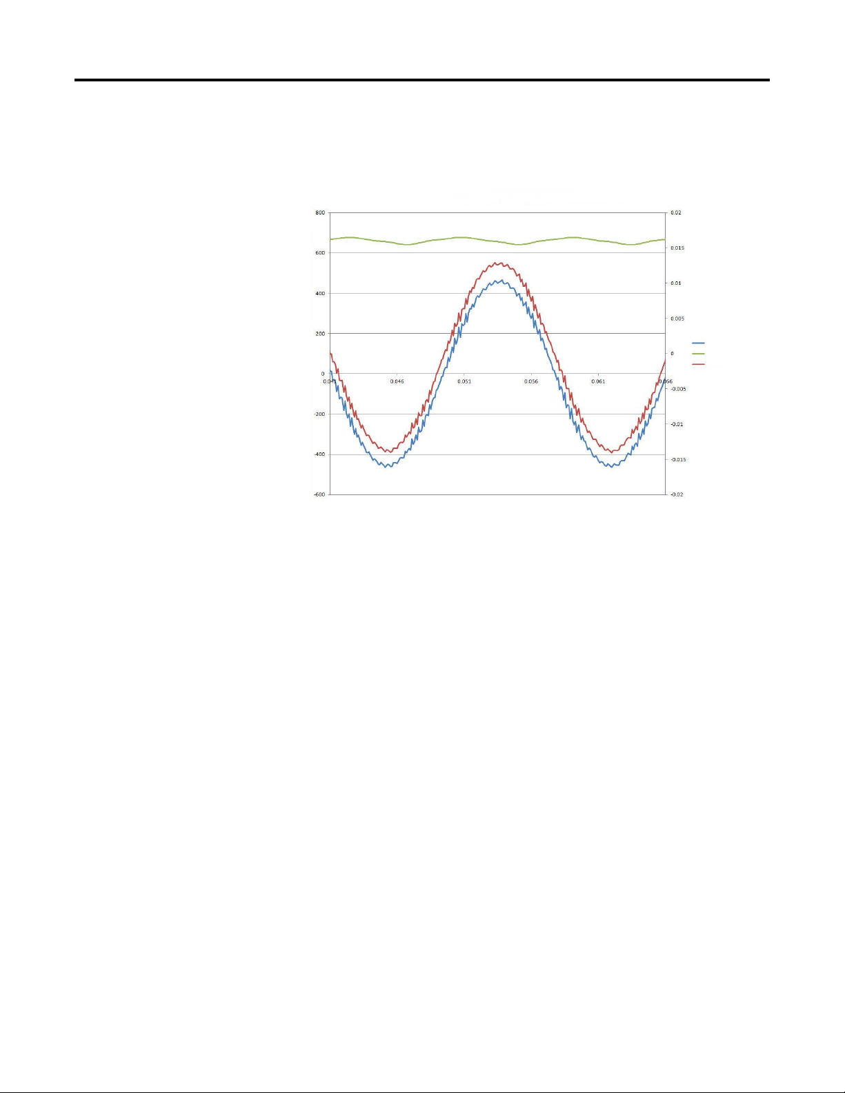
This is a plot showing output voltage, output current, and DC Bus voltage. Here
you can see the current following the voltage in a typical PWM output.
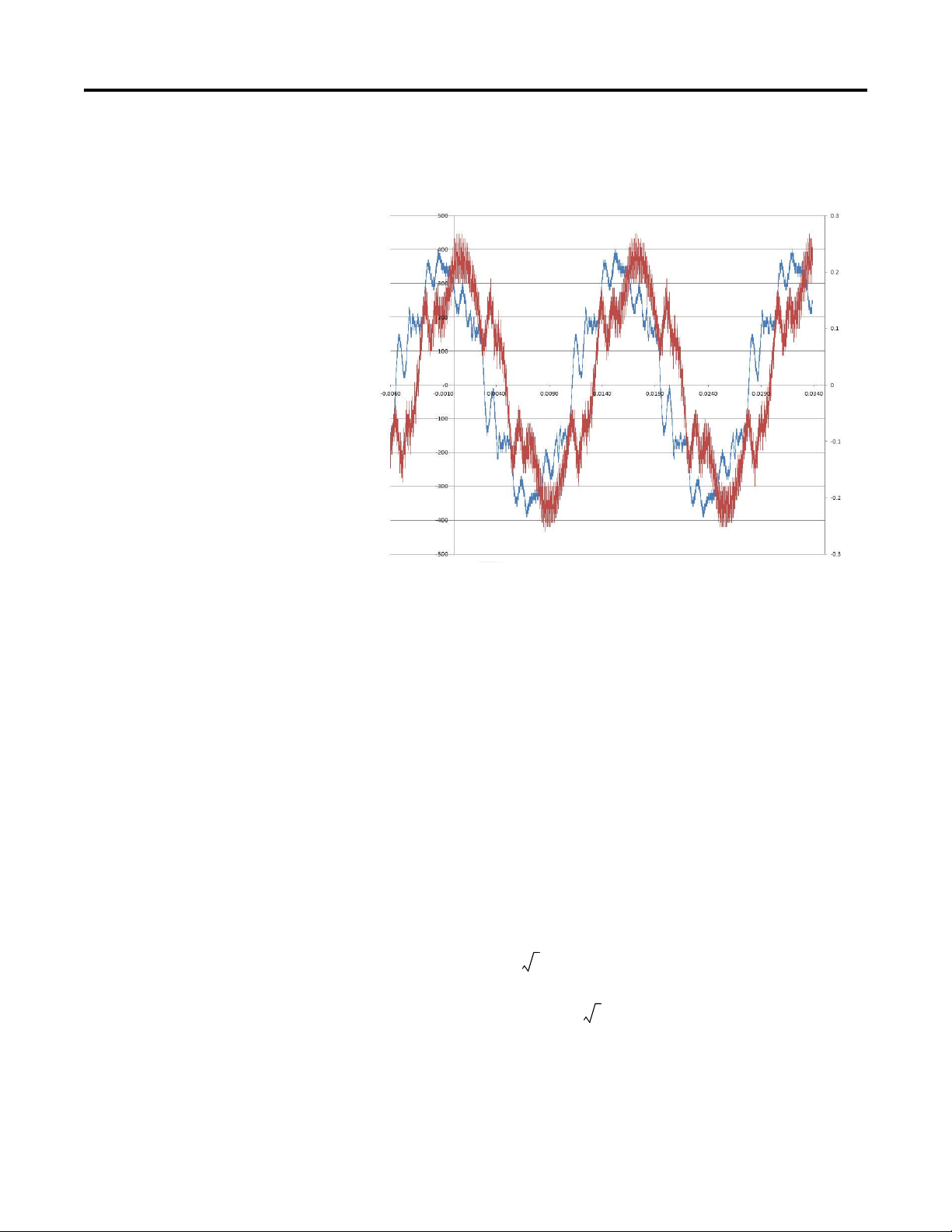
This plot enlarges some of the pulses to see the current and its shape.
Notice the tops have an abrupt change to them. Any rounding of the wave form
at the top is due to the type of resistor used. The resistors used for this plot are the
grid type resistors where the resistor element is coiled along its length, adding a
certain amount of inductance. This inductance helps round over the leading edge
of the current.
Rockwell Automation Publication 750-RM002B-EN-P - September 2013 21
Page 22
Chapter 1 Drive Configuration
Single Phase - PWM into Resistor - No Reactor
Vol tag e
DC Bus
Curren t
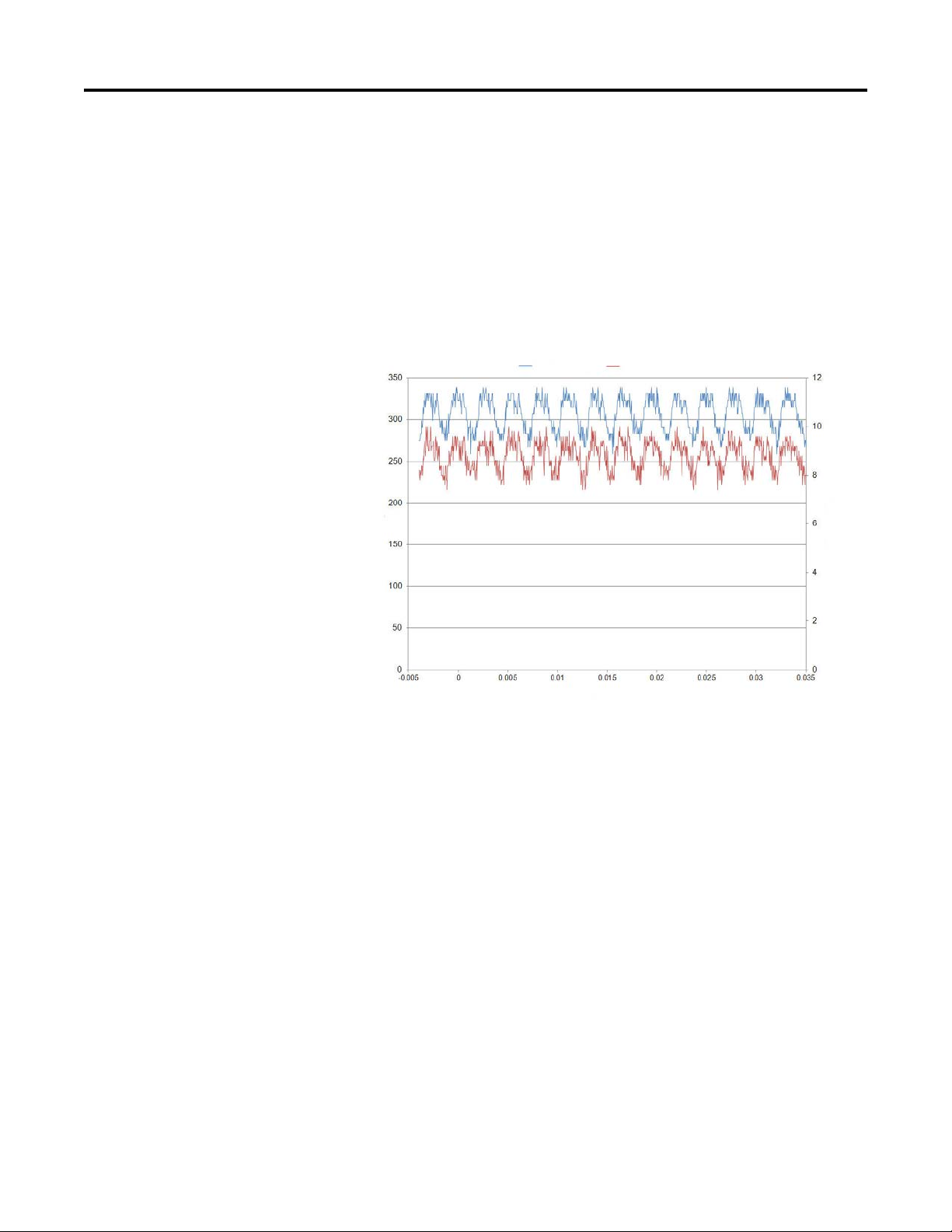
Below is the same plot with a reactor added in series. These waveform look like a
sine wave and that is a function of how much inductance is added. However, the
increased voltage drop must be accounted for.
Another option is to have a sine wave filter in the circuit. This lets unshielded
cable to be used without the worry of PWM generated noise being injected into
the facility. The cost of shielded cable versus a sine wave filter, Among other
factors, has to be weighed.
When using single phase operation, connect the load to the U and V phases. The
W phase is energized but is not used.
Enter your maximum current into the Motor NP Amps parameter. Also use this
value in the Current Limit parameter. When started the drive attempts to ramp
to the commanded voltage. If current limit is hit, the drive levels off or reduce the
voltage to satisfy the current limit.
Notice the DC Bus voltage ripple in two of the plots above. If this ripple is high
enough in magnitude, it can cause the drive to trip on an Input Phase Loss fault.
This is due to the drive monitoring the bus ripple and if a certain delta between
max volts and min volts exists for a certain amount of time, the drive assumes an
input phase was lost. This fault can be disabled by setting P462 [InPhase
LossActn] to option 0 “Ignore.”
Three Phase Output
If you are driving as resistive load, configure it in a three phase arrangement to
avoid using the single phase mode of adjustable voltage. Use a sine wave filter to
keep PWM off the resistors. If the resistors are of the ceramic type, it is possible to
crack the resistor using PWM.
22 Rockwell Automation Publication 750-RM002B-EN-P - September 2013
Page 23
Drive Configuration Chapter 1
XL 2 pi× f× H×=
XL12pi× 60× 1.2 1000⁄()× 0.45ohm==
XL22pi× 60× 5 1000⁄()× 1.88ohm==
XL32pi× 60× 5 1000⁄()× 1.88ohm==
XL42pi× 60× 3 1000⁄()× 1.13ohm==
IVXL 3×()⁄=
VIXL× 3×=
The following is a plot of voltage and current at the reactor. The output of the
drive is sent through a sine wave filter then to the reactor. The shape of the
waveform is determined by the amount of capacitance in the sine wave filter.
If you wanted to know what voltage you can expect at the three phase reactor,
consider an example where the user has four reactors in series. The inductance of
each is 1.2mH, 5mH, 5mH and 3mH. First item to calculate is XL for each
reactor. .
Now total it. XL1 + XL2 + XL3 + XL4 = 5.35 ohm.
For a three phase reactor the current is represented by the
equation,
Isolate the voltage.
The current value can be what the least rating of the reactors are or if the rating
are greater than the drive rating, use the drive rating. In this case the drive is rated
for 14 amps.
Rockwell Automation Publication 750-RM002B-EN-P - September 2013 23
Page 24
Chapter 1 Drive Configuration
V 14 5.35× 1.73× 129.8==
DC Voltage
Resistor Current
Times
DC Voltage
Resistor Current
So plug in the numbers.
So 14 amps is realized when the voltage is 129.8 on the output. A drive with a
voltage rating of 240V AC could be selected.
Below is a waveform of voltage and current at a resistor. The output of the drive
runs through a sine wave filter. Then this is connected to a one to one
transformer. This output is then sent to a bridge rectifier giving us pure DC.
With the use of a feedback board and the drives PI loop, the voltage at the resistor
was steady even if the resistance changed while running.
Other
Setting the frequency acceleration time to zero results in the drive outputting a
DC voltage waveform.
If the frequency accel time is set between 0 and 1, this could trigger and anomaly
24 Rockwell Automation Publication 750-RM002B-EN-P - September 2013
where the drive outputs a frequency not equal to the commanded frequency. The
Page 25
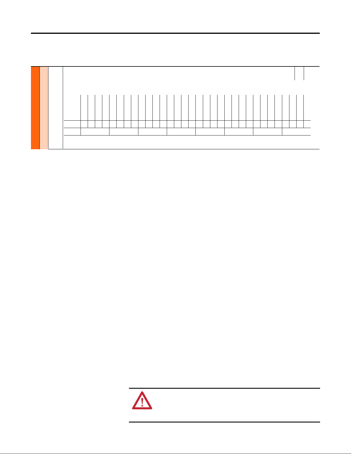
40 Mtr Options Cfg
Options
Reserved
Reserved
Reserved
Reserved
Reserved
Reserved
Reserved
Reserved
Reserved
Reserved
Reserved
Reserved
Reserved
Reserved
Reserved
Reserved
Jerk Select
Not Used
Common Mode
Xsistor Diag
Elect Stab
DB WhileStop
PWM FreqLock
AsyncPWMLock
PWM Type Sel
RS Adaption
Reflect Wave
Mtr Lead Rev
EnclsTrqProv
(1)
(1) 755 drives only.
Trq ModeJog
Trq ModeStop
Zero TrqStop
Default00000000000000000001100011100111
Bit 323029282726252423222120191817161514131211109876543210
Mtr Ctrl Options
MOTOR CONTROL
Drive Configuration Chapter 1
cause of this anomaly is the introduction of the jerk function. This bit needs to be
off during this condition.
RW 32-bit
Motor Options Configuration
Configuration of motor control-related functions. For motors abo ve 200 Hz, a carrier frequency of 8 kHz or higher is recommended. Consider drive derate and motor
lead distance restrictions.
Integer
When using single phase operation, connect the load to the U and V phases. The
W phase is energized but is not used.
Using a DC output can result in thermal issues. The drive may need to be
derated.
Auto Restart
Investigate Possible Derating
Derate drive for sine wave filter.
Motor or drive overload is not affected by adjustable voltage mode.
The Auto Restart feature provides the ability for the drive to automatically
perform a fault reset followed by a start attempt without user or application
intervention. Provided the drive has been programmed with a 2 wire control
scheme and the Run signal is maintained. This enables remote or unattended
operation. Only certain faults are allowed to be reset. Faults listed as NonResettable in the programming manual indicate possible drive component
malfunction and are not resettable.
Use caution when enabling this feature, because the drive attempts to issue its
own start command based on user selected programming.
Configuration
Setting P348 [Auto Rstrt Tries] to a value greater than zero enables the Auto
Restart feature. Setting the number of tries equal to zero disables the feature.
ATT EN TI ON : Equipment damage and/or personal injury may result if this
parameter is used in an inappropriate application. Do not use this function
without considering applicable local, national and international codes,
standards, regulations or industry guidelines.
Rockwell Automation Publication 750-RM002B-EN-P - September 2013 25
Page 26

Chapter 1 Drive Configuration
P349 [Auto Rstrt Delay] sets the time, in seconds, between each reset/run
attempt.
The auto reset/run feature supports the following status information.
• P936 [Drive Status 2] Bit 1 “AuRstrCntDwn” provides indication that an
Auto Restart attempt is presently counting down and the drive attempts to
start at the end of the timing event.
• P936 [Drive Status 2] Bit 0 “AutoRstr Act” indicates that the auto restart
has been activated.
Operation
The typical steps performed in an Auto Reset/Run cycle are as follows.
1. The drive is running and an Auto Reset Run fault occurs, thus initiating
the fault action of the drive.
2. After the number of seconds in P349 [Auto Rstrt Delay], the drive
automatically performs an internal Fault Reset, resetting the faulted
condition.
3. The drive then issues an internal Start command to start the drive.
4. If another Auto Reset Run fault occurs, the cycle repeats itself up to the
number of attempts set in P348 [Auto Rstrt Tries].
5. If the drive faults repeatedly for more than the number of attempts set in
P348 [Auto Rstrt Tries] with less than five minutes between each fault, the
Auto Reset/Run is considered unsuccessful and the drive remains in the
faulted state.
6. If the drive remains running for five minutes or more because the last
reset/run without a fault, or is otherwise stopped or reset, the Auto Reset/
Run is considered successful. The Auto Restart status parameters are reset,
and the process repeats if another auto resettable fault occurs.
See Aborting an Auto-Reset/Run Cycle for information on how the
Reset/Run cycle can be aborted.
Beginning an Auto-Reset/Run Cycle
The following conditions must be met when a fault occurs for the drive to begin
an Auto Reset/Run cycle:
• The fault type must be Auto Reset Run.
• P348 [Auto Rstrt Tries] setting must be greater than zero.
• The drive must have been running, not jogging, not auto tuning, and not
stopping, when the fault occurred. (A DC Brake state is part of a stop
sequence and therefore is considered stopping.)
26 Rockwell Automation Publication 750-RM002B-EN-P - September 2013
Page 27

Drive Configuration Chapter 1
Aborting an Auto-Reset/Run Cycle
During an Auto Reset/Run cycle the following actions/conditions abort the
reset/run attempt process.
• A stop command is issued from any source. (Removal of a 2-wire run-fwd
or run-rev command is considered a stop assertion.)
• A fault reset command is issued from any source.
• The enable input signal is removed.
• P348 [Auto Rstrt Tries] is set to zero.
• A Non-Resettable fault occurs.
• Power to the drive is removed.
• The Auto Reset/Run Cycle is exhausted.
After all [Auto Rstrt Tries] have been made and the drive has not successfully
restarted and remained running for five minutes or more, the Auto Reset/Run
cycle is considered exhausted and therefore unsuccessful. In this case the Auto
Reset/Run cycle terminates and an F33 “AuRsts Exhaust” fault is indicated by
P953 [Fault Status B] Bit 13 “AuRstExhaust.”
Auto/Manual
The purpose of the Auto/Manual function is to permit temporary override of
speed control and/or exclusive ownership of logic (start, run, direction) control.
A manual request can come from any port, including HIM, digital input or other
input module. However, only one port can own manual control and must release
the drive back to auto control before another port can be granted manual control.
When in Manual mode, the drive receives its speed reference from the port that
requested manual control, unless otherwise directed by the Alternate Manual
Reference Select.
The HIM can request Manual control by pressing the Controls key followed by
the Manual key. Manual control is released by pressing the Controls key followed
by Auto. When the HIM is granted manual control, the drive uses the speed
reference in the HIM. If desired, the auto speed reference can be automatically
preloaded into the HIM when entering HIM manual control, so that the
transition is smooth.
Manual control can also be requested through a digital input. To do this, a digital
input has to be set to request Manual control through P172 [DI Manual Ctrl].
Digital Input Manual control requests can be configured to use their own
alternative speed reference to control the drive. Digital inputs can also be used in
conjunction with Hand-Off-Auto Start to create a three way HOA switch that
incorporates Manual mode.
The Safe Speed Monitor Option Module uses Manual mode to control the speed
of the drive when entering Safe Limited Speed monitoring.
Rockwell Automation Publication 750-RM002B-EN-P - September 2013 27
Page 28

Chapter 1 Drive Configuration
Auto/Manual Masks
The port configuration of the Auto/Manual feature is performed through a set of
masks. Together, these masks set which ports can control the speed and/or logic
control of the drive as well as which ports can request Manual control. The masks
are configured by setting a 1 or 0 in the bit number that corresponds to the port
(Bit 1 for port 1, Bit 2 for port 2, and so forth). Digital Inputs are always
configured through Bit 0, regardless of what port the module physically resides
in. If both [Manual Ref Mask] and [Manual Cmd Mask] for a particular port are
set to 0, that port is unable to request manual control.
P324 [Logic Mask]
Logic Mask enables and disables the ports from issuing logic commands (such as
start and direction) in any mode. Stop commands from any port are not masked
and still stop the drive.
P325 [Auto Mask]
Auto Mask enables and disables the ports from issuing logic commands (such as
start and direction) while in Auto mode. Stop commands from any port are not
masked and still stop the drive.
P326 [Manual Cmd Mask]
Manual Command Mask enables and disables the ports from exclusively
controlling logic commands (such as start and direction) while in Manual mode.
If a port assumes Manual control, and the corresponding bit for the port in the
[Manual Cmd Mask] is set, no other port is able to issue logic commands. Stop
commands from any port are not masked and still stops the drive.
P327 [Manual Ref Mask]
Manual Reference Mask enables and disables the ports from controlling the
speed reference while in Manual mode. If a port assumes manual control, and the
corresponding bit for the port in the [Manual Ref Mask] is set, the drive is
commanded to the speed reference from that port. An alternate speed reference
can be commanded using P328 [Alt Man Ref Sel]. If the respective bit for the
manual control port is not set, then the drive follows its normal automatic speed
reference, even in Manual mode.
Alternate Manual Reference Select
By default, the speed reference used in Manual mode comes from the port that
requested manual control (For example, if a HIM in port 1 requests manual
control, the speed reference in Manual mode comes from port 1). If instead it is
desired to use an a different speed reference, P328 [Alt Man Ref Sel], can be used.
The port selected in the parameter is used for manual reference regardless of
which port requested manual control, as long as the port in manual control is
allowed to set the manual reference per P327 [Manual Ref Mask]. If P328 [Alt
Man Ref Sel] is an analog input, the maximum and minimum speeds can be
configured through P329 [Alt Man Ref AnHi] and P330 [Alt Man Ref AnLo].
28 Rockwell Automation Publication 750-RM002B-EN-P - September 2013
Page 29
Drive Configuration Chapter 1
ESC
REF
MANUAL
FBKREF
REMOVE
HIM
EDIT
REF
FWDREV
REF
JOG HELP
Control Sc reen Key Functio n Map
corresponds to Navigation/Number Keys
Stopped
0.00 Hz
AUTO
F
Stopped
0.00 Hz
MAN
F
00
Stopped
0.00 Hz
AUTO
Host Drive
240V 4.2A
20G...D014
ESC REF TEXT
F
PAR#
For analog input between the minimum and maximum, the drive derives the
speed from these parameters through linear interpolation.
The P328 [Alt Man Ref Sel] manual reference overrides all other manual speed
references, including P563 [DI ManRef Sel].
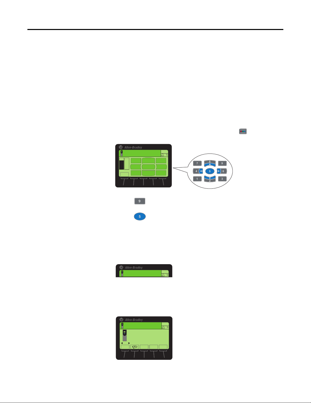
HIM Control
Manual Control can be requested through an HIM device attached to port 1, 2,
or 3. The proper bits must be set in the masks (P324 [Logic Mask], P326
[Manual Cmd Mask], and P327 [Manual Ref Mask]) for the port that the HIM
is attached. To request control through the HIM, press the (Controls) key
to display the Control screen.
Press the (Manual) key.
Press the (Edit) key to confirm that you want to switch to Manual mode.
If the request is accepted, the HIM displays “MAN” in the top right corner. The
display does not indicate if the drive is in Manual, but rather if that particular
HIM has Manual control. A HIM still displays “AUTO” if it does not have
ownership of the Manual mode, even if the drive itself is in Manual mode. To see
if the drive is in Manual mode, check P935 [Drive Status 1] Bit 9.
When a HIM has Manual control of the drive, the drive uses the speed reference
from the HIM unless overridden by P328 [Alt Man Ref Sel]. To change the speed
reference on the HIM, navigate to the Status screen and press the middle soft key
labeled REF.
Rockwell Automation Publication 750-RM002B-EN-P - September 2013 29
Page 30
Chapter 1 Drive Configuration
ESC
REF
MANUAL
FBKREF
REMOVE
HIM
EDIT
REF
FWDREV
REF
JOG HELP
Control Scre en Key Function Map
corresponds to Navigation/Number Keys
Stopped
0.00 Hz
AUTO
F
Current Speed
With Manual Preload
Without Manual Preload
Desired Speed
Set in HIM
Manual Mode
Requested
Desired Manual Speed
Last Speed Used in HIM
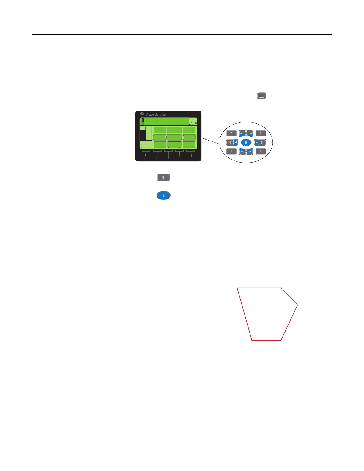
If the request is not accepted, a message indicates that “Manual Control is not
permitted at this time.” The most likely causes are that manual control is disabled
for the port or that another port currently has manual control. To check which
port has manual control, look at P924 [Manual Owner].
To release Manual mode from the HIM, press the (Controls) key to display
the Control screen.
Press the (Auto) key.
Press the (Edit) key to confirm that you want to switch to Auto mode.
HIM Preload
Before taking a manual control speed reference from a HIM, the drive can
preload its current speed into the HIM to provide a smooth transition. Without
this feature, the drive immediately transitions to whatever speed was last used in
the HIM, before the operator has a chance to make their adjustment. With this
feature, the drive maintains its current speed until the operator sets the speed to
the desired manual reference.
30 Rockwell Automation Publication 750-RM002B-EN-P - September 2013
The Auto/Manual HIM Preload is configured through P331 [Manual Preload].
Ports 1, 2, and 3 can be configured to have the speed reference preloaded into the
HIM by setting bits 1, 2, and 3 respectively.
Page 31

Drive Configuration Chapter 1
Manual Speed Reference HIM (DPI Port 1)
Manual Control (Port 5, Input 3)
Automatic Speed Reference (Port 14)
Example Scenario
The drive has a HIM in port 1 and a 24V DC I/O module in port 5. You want to
select manual control from a digital input 3 on the I/O module. You want the
embedded EtherNet/IP port to be the source for the speed reference in
Automatic mode, and the HIM to be the source for the speed reference in
Manual mode.
Required Steps
1. Set P172 [DI Manual Ctrl] to Port 5-I/O Module > 1-Dig In Sts > 3 –
Input 3.
2. Set P328 [Alt Man Ref Sel] = 871 Port 1 Reference 3. Set P331 [Manual
Preload] = 0000 0000 0000 0010, Bit 1 enables the preloading of the
speed feedback value to the HIM at port 1 when the HIM is granted
manual control.
Digital Input Control
A Digital Input can be configured to request manual control through P172 [DI
Manual Ctrl]. When setting up the Auto/Manual masks, digital inputs are
configured through Bit 0, regardless of what port the module physically resides
in.
Rockwell Automation Publication 750-RM002B-EN-P - September 2013 31
Page 32

Chapter 1 Drive Configuration
+24V
+10V
HA
O
XOO
OOX
XOO
DI 0: Stop
DI 1: HOA Start and
Manual Control
Analog IN 0: DI Manual
Speed Reference
Speed Potentiometer
A speed reference for Manual mode from a digital input can be set by selecting a
port in P328 [Alt Man Ref Sel]. This however causes all manual requests to use
that port as a reference, whether the request was from the digital input or from a
HIM. A separate manual reference port for use only when the request comes
from a digital input can be configured through P563 [DI ManRef Sel]. (To see
P564 [DI ManRef AnlgHi], set P301 [Access Level] to 1 “Advanced.”) If P328
[Alt Man Ref Sel] is configured, it overrides P563 [DI ManRef Sel] and provides
the manual reference.
If P563 [DI ManRef Sel] is an analog input, the maximum and minimum speeds
can be configured through P564 [DI ManRef AnlgHi] and P565 [DI ManRef
AnlgLo]. For analog input between the minimum and maximum, the drive
derives the speed from these parameters through linear interpolation.
Hand-Off-Auto
The Auto/Manual feature can be used in conjunction with a Hand-Off-Auto
Start to create a H-O-A switch that starts the drive and requests manual control
at the same time, allowing for a local speed reference to control the drive. See
Hand-Off-Auto
on page 64 for more details on the Hand-Off-Auto Start feature.
In the circuit below, a speed potentiometer was added to the analog input to
provide a speed reference to the drive. When the H-O-A switch is moved from
Auto to Hand, the digital input block requests manual control and issues a start
command to the drive. If the digital input port receives manual control, the drive
accelerates to the reference speed from the analog input. All attempts to change
the speed except from the analog input are blocked. If the drive is stopped while
in Hand, switch the H-O-A switch to Off and then back to Hand to restart the
drive.
If another port has manual control of the drive, but does not have exclusive
ownership of the logic commands (due to P326 [Manual Cmd Mask]), turning
the switch to Hand causes the drive to begin moving but for the analog input to
have no control over the speed.
32 Rockwell Automation Publication 750-RM002B-EN-P - September 2013
Page 33

Drive Configuration Chapter 1
For this circuit, set the following parameters (P301 [Access Level] must be set to
1 “Advanced” to see P563 [DI ManRef Sel]).
Number Parameter Name Value
158 DI Stop Digital Input 0
172 DI Manual Ctrl Digital Input 1
176 DI HOA Start Digital Input 1
324 Logic Mask xxxxxxxxxxxxxxx1 (Digital In)
326 Manual Cmd Mask xxxxxxxxxxxxxxx1 (Digital In)
327 Manual Ref Mask xxxxxxxxxxxxxxx1 (Digital In)
563 DI ManRef Sel Anlg In0 Value
The drive requests Manual mode, start, and tracks the reference speed coming
from the Analog Input when the H-O-A switches to Hand. (The HIM still reads
Auto. This display changes only when the HIM has control of Manual mode).
Safe Limited Speed
Safe Limited Speed through the PowerFlex Safe Speed Monitor option module
uses Manual mode to control the speed of the drive. When Safe Limited Speed
monitoring is enabled, the safety module requests manual control of the drive. If
the drive does not reach a safe speed, as defined on the option module by P55
[Safe Speed Limit] and within P53 [LimSpd Mon Delay], the drive faults.
While the option module uses the Manual mode, it has no way to provide a speed
reference or start the drive. The following parameters must thus be configured.
P326 [Manual Cmd Mask]
Turn off the bit corresponding to the safety option’s port to allow modules
installed in other ports to continue to control the drive when it is operating in
Manual mode. For example, if the safety option is installed in port 6, then turn
off Bit 6 in this parameter.
P327 [Manual Ref Mask]
Turn on the bit corresponding to the safety option’s port to allow the safety
option to command the drive to use its Manual Speed Reference when it is
operating in Manual mode. For example, if the safety option is installed in port 6,
then turn on Bit 6 in this parameter.
P328 [Alt Man Ref Sel]
Set this parameter to select the desired speed reference when the drive is
operating in Manual mode. For example, set this parameter to the value Port 0:
Preset Speed 1 to configure the drive to use P571 [Preset Speed 1] as the Manual
Speed Reference. In this case, P571 [Preset Speed 1] must be less than P55 [Safe
Speed Limit] in the safety option to avoid causing an SLS Speed Fault.
See the Safe Speed Monitor Option Module for PowerFlex 750-Series AC Drives
Safety Reference Manual, publication 750-RM001
Rockwell Automation Publication 750-RM002B-EN-P - September 2013 33
, for more information.
Page 34

Chapter 1 Drive Configuration
Automatic Device Configuration
Automatic Device Configuration (ADC) supports the automatic download of
configuration data to a Logix controller that has an EtherNet/IP connection to a
PowerFlex 755 drive (firmware 4.001 or later) and its associated peripherals
ADC is supported in the following:
• RSLogix 5000 software, version 20 or later
• Studio 5000 environment, version 21 or later
Project files (.ACD files) created with this software contain the configuration
settings for PowerFlex drives in the project. When the project is downloaded to
the controller, the configuration settings are transferred to controller memory.
Earlier programming software required a manual process to download
configuration settings to the controller.
ADC can also work in tandem with Firmware Supervisor. If Firmware Super visor
is set up and enabled for a drive (Exact Match keying must be used), the drive/
peripheral is automatically upgraded (if necessary) prior to any ADC operation
for that port.
Information on Automatic Device Configuration (ADC) can be found in the
PowerFlex 755 Embedded EtherNet/IP Adapter User Manual, publication
750COM-UM001
topics:
• Description of the ADC functionality
• How the Drive Add-On Profiles (AOPs) affect ADC
• Configuring a PowerFlex 755 Drive (firmware 4.001 or later) for ADC
• ADC and Logix Memory
• Storing the Drive’s and Peripherals’ Firmware in the Logix Controller
(Firmware Supervisor)
• Special Considerations When Using a DeviceLogix software Program
• Special Considerations When Using a 20-750-S1 Safe Speed Monitor
Module
• Monitoring the ADC Progress
• Examples of potential issues and solutions
, Chapter 4, Configuring the I/O includes the following
34 Rockwell Automation Publication 750-RM002B-EN-P - September 2013
Page 35

Drive Configuration Chapter 1
Autotune
The Autotune feature is used to measure motor characteristics. The Autotune
feature is made up of several individual tests, each of which is intended to identify
one or more motor parameters. These tests require motor nameplate information
to be entered into the drive parameters. Although some of the parameter values
can be changed manually, measured values of the motor parameters provide the
best performance. Each motor control mode requires its own set of tests to be
performed. The information obtained from these measurements is stored in the
drives non volatile memory for use during operation of the drive. The feature lets
these tests to be separated into tests that don’t require motor rotation (Static
Tune), all tests within the selected control mode (Rotate Tune), or if the control
mode requires the Inertia (Inertia Tune).
The Autotune tests are selected through the P70 [Autotune]. The feature
provides a manual or automatic method for setting P73 [IR Voltage Drop], P74
[Ixo Voltage Drop] and P75 [Flux Current Ref ]. Valid only when P35 [Motor
Ctrl Mode] is set to 1 “Induction SV,” 2 “Induct Econ,” or 3 “Induction FV.”
Other motor control modes such as Permanent Magnet and Interior Permanent
magnet, populate other parameters associated with those control modes. See the
autotune parameter set below.
Tes ts
Four Autotune selections are available in the PowerFlex 755 drive control. All
four selections are selected from the Autotune parameter.
P70 [Autotune]
• 0 = Ready
• 1 = Calculate
• 2 = Static Tune
• 3 = Rotate Tune
• 4 = Inertia Tune
Ready
Parameter returns to this setting following a Static Tune or Rotate Tune, at which
time another start transition is required to operate the drive in Normal mode. It
also permits manually setting P73 [IR Voltage Drop], P74 [Ixo Voltage Drop],
and P75 [Flux Current Ref ].
Rockwell Automation Publication 750-RM002B-EN-P - September 2013 35
Page 36

Chapter 1 Drive Configuration
IMPORTANT
Calcula te
When the Autotune parameter is set to Calculate (default), the drive uses motor
nameplate data to automatically set P73 [IR Voltage Drop], P74 [Ixo Voltage
Drop], P75 [Flux Current Ref ] and P621 [Slip RPM at FLA].
P73 [IR Volt Drop], P87 [PM IR Voltage], P79 [Encdrlss VltComp], P74 [Ixo
Voltage Drop], P75 [Flux Current Ref ], P93 [PM Dir Test Cur], and the Slip
Frequency parameters are updated based on nameplate parameter values. When a
nameplate parameter value is changed, the Autotune parameters are updated
based on the new nameplate values.
When using Calculate, updated values come from a lookup table.
Static Tune
When the Autotune parameter is set to Static, only tests that do not create motor
movement are run. A temporary command that initiates a non-rotational motor
stator resistance test for the best possible automatic setting of P73 [IR Voltage
Drop] in all valid modes and a non-rotational motor leakage inductance test for
the best possible automatic setting of P74 [Ixo Voltage Drop] in a Flux Vector
(FV) mode. A start command is required following initiation of this setting.
Used when motor cannot be rotated.
Rotate Tune
The actual tests performed when Static and Rotate Tune selections are made,
differ for the available motor control modes, Feedback Type and motor type
selected. The tests performed are dependent on the settings of P35 [Motor Ctrl
Mode], P125 [Pri Vel Fdbk Sel], and P70 [Autotune]. The parameters that are
updated are then dependent on the tests run and in some cases calculated values
for some parameters are used to update other parameters. Refer to Ta b l e 3
A temporary command initiates a Static Tune and is then followed by a rotational
test for the best possible automatic setting of P75 [Flux Current Ref ]. In Flux
Vector (FV) mode, with encoder feedback, a test for the best possible automatic
setting of P621 [Slip RPM at FLA] is also run. A start command is required
following initiation of this setting.
If using rotate tune for a Sensorless Vector (SV) mode, uncoupled the motor from the
load or results can be invalid. With a Flux Vector (FV) mode, either a coupled or
uncoupled load produces valid results. Caution must be used when connecting the
load to the motor shaft and then performing an autotune. Rotation during the tune
process can exceed machine limits.
.
36 Rockwell Automation Publication 750-RM002B-EN-P - September 2013
Page 37

Drive Configuration Chapter 1
Table 3 - Autotune Value Source
Control
Mode
VF Induction NA Static ON OFF OFF OFF OFF ON OFF OFF OFF OFF
FV Induction Encoder Static ON ON ON OFF OFF OFF OFF OFF OFF OFF
Motor
Type
PM NA Static ON OFF OFF OFF OFF OFF OFF OFF OFF OFF
Reluctance NA Static ON OFF OFF OFF OFF OFF OFF OFF OFF OFF
PM Encoder Static OFF OFF OFF OFF OFF OFF OFF OFF OFF OFF
Reluctance Encoder Static OFF OFF OFF OFF OFF OFF OFF OFF OFF OFF
Feedback
Select
EncoderlessStaticONONONONOFFOFFOFFOFFOFFOFF
Encoderless Static ON ON OFF OFF OFF OFF OFF OFF OFF OFF
Encoderless Static OFF OFF OFF OFF OFF OFF OFF OFF OFF OFF
Autotune Rs Xo Idlt Rslt Id Rsld Slip Encrls Cemf PmOffset
Dynamic ON OFF OFF OFF ON ON OFF OFF OFF OFF
Dynamic ON OFF OFF OFF OFF OFF OFF OFF OFF OFF
Dynamic ON OFF OFF OFF ON OFF OFF OFF OFF OFF
Dynamic ON ON OFF OFF ON OFF ON OFF OFF OFF
DynamicONONONONONONOFFONOFFOFF
Dynamic ON ON OFF OFF OFF OFF OFF OFF ON ON
Dynamic ON ON OFF OFF OFF OFF OFF OFF ON OFF
Dynamic OFF OFF OFF OFF OFF OFF OFF OFF OFF OFF
Dynamic OFF OFF OFF OFF OFF OFF OFF OFF OFF OFF
Inertia Tune
The Inertia Autotune selection involves only one test. Several parameters are
updated from the test results. Refer to the tables in the Individual Tests section.
A temporary command initiates an inertia test of the motor/load combination.
The motor ramps up and down while the drive measures the amount of inertia.
This option applies only to FV modes selected in P35 [Motor Ctrl Mode].
Obtain final test results with the load coupled to the motor as long as the rotation
won’t damage the machine.
Test Dependencies
When running the flux test, the selected accel rate is used unless it is less than 10
seconds. In this case, 10 seconds is forced. In the case of the Inertia test, a 0.1
second accel rate is used. The selected direction used during normal operation is
used for all rotation tests. Also, during any rotate test, the normal speed limits are
enforced.
The thermal manager is always being run in the 2 ms loop, which provides
protection during all of the Autotune tests.
Rockwell Automation Publication 750-RM002B-EN-P - September 2013 37
Page 38

Chapter 1 Drive Configuration
Tacc
WK2ΔN×
308 t()
-------------------------=
WK
2
Tacc 308 t()××
ΔN
--------------------------------------=
Individual Tests
Some of the following tests are executed during an Autotune.
Resistance Test
This test is a Static test whether Static or Rotate is selected. Used to measure
Stator resistance.
Inductance Tests
This test is a Static test whether Static or Rotate is selected. One test is used for
Induction motors and a another is used for PM motors. The result from the
Induction test is placed into the Ixo parameter and the PM test is placed into the
IXd and IXq parameters.
Flux Test
This test is a Rotate test that measures the current under a no load condition. The
results are used for the flux current. If a Static test is used, the resulting value is
from a lookup table.
Slip Test
This test is a Rotate test that measures the difference between the rotor speed and
the stator speed. This measurement is taken during acceleration.
PM Offset Test
This test can create a small amount of motor movement so it needs to be
performed with the Rotate selection. The test reads the encoder position when
the drive outputs zero hertz.
Inertia Test
This test is a stand alone test that is used to measure the system inertia.
The drive sets this value in P76 [Total Inertia] as seconds of inertia. This reflects
the time it takes to accelerate the load at 100% torque to base speed. This
2
information can be very useful in determining the total inertia (in lb•ft
connected to a motor shaft.
) that is
Using the following formula,
and rearranging it to
38 Rockwell Automation Publication 750-RM002B-EN-P - September 2013
Page 39

Drive Configuration Chapter 1
HP
T Speed×
5252
-------------------------=
T
HP 5252×
Speed
-----------------------=
T
10 5252×
1785
------------------- -=
WK
2
Tacc 308× t()×
ΔN
--------------------------------------=
we have a formula that isolates the connected inertia.
For the variables, Tacc is the 100% rating of the drive in lb•ft. Let’s say I’m using a
10 Hp drive with a 10 Hp motor. We can rearrange the Horsepower formula
below to solve for torque in lb•ft.
My motor is 10hp, 1785RPM,
and rearranging it to
So let’s plug in the numbers. T = lb•ft
And (t) comes from what the drive reports as seconds of inertia after running the
inertia tune. Let’s say that the drive reported 2.12 seconds of inertia. And now
organizing the variables we have
Tacc = 29.42
(t) = 2.12
N = 1785
2
plugging these into the formula, WK
After these calculations, one can conclude that the connected inertia is equal to
10.76 lb•ft
What effect can P71 [Autotune Torque] have on these calculations? Regardless
of the value entered here, the drive interpolates as if this value was 100%. So the
seconds of inertia reported by the drive always reflects 100% torque.
2
. Multiplying by 0.04214011 you get 0.453 kg•m2.
= 10.76
CEMF Test
This is a Rotate test used to measure a PM motors CEMF.
Autotune Parameters Information about some other Autotune Parameters not
covered above.
Rockwell Automation Publication 750-RM002B-EN-P - September 2013 39
Page 40

Chapter 1 Drive Configuration
Autotune Parameters
P71 [Autotune Torque]
Typically the default value of 50% is sufficient for most applications. You have the
option of increasing this value or decreasing the value.
P73 [IR Voltage Drop]
The voltage drop due to resistance.
P74 [Ixo Voltage Drop]
The voltage drop due to Inductance.
P75 [Flux Current Ref ]
The current necessary to flux up the motor. This value come from a lookup table
for Static tunes and is measured during a Rotate tune. Obviously a rotate tune
gives more accurate results.
P76 [Total Inertia]
Reported as seconds of inertia. See description above.
P77 [Inertia Test Lmt]
A number entered in this parameter limits the inertia tune test to a maximum
number of revolutions. If violated, the drive faults on F144 “Autotune Inertia.”
Also, when a value is entered and the drive determines that the number of
revolutions will be exceeded it goes into a decel and stops before the value is
exceeded.
P78 [Encdrlss AngComp] and P79 [Encdrlss VltComp]
These parameters are valid only for Flux Vector motor control mode and open
loop. P78 is populated only by a rotate tune. P79 is populated by a Static
measurement.
P80 [PM Cfg]
This configuration parameter enables certain tests to be performed based on the
motor connected.
Permanent Magnet Motors
Parameters P81 through P93 and P120 are all populated by an autotune when
the motor selected is permanent magnet. The value for these parameters are
determined only by a rotate tune.
Interior Permanent Magnet Motors
Parameters P1630 through P1647 are all populated by an autotune when the
motor selected is interior permanent magnet. The value for these parameters are
determined only by a rotate tune.
40 Rockwell Automation Publication 750-RM002B-EN-P - September 2013
Page 41

Drive Configuration Chapter 1
Motoring Regenerating
Auxiliary Power Supply
Bus Regulation
The optional Auxiliary Power Supply module, 20-750-APS, is designed to
provide power to a single drive’s control circuitry in the event incoming supply
power to the drive is removed or lost.
When connected to a user supplied 24V DC power source, the communication
network functions remain operational and on-line. A DeviceNet program can
also continue to run and control any associated input and outputs.
The auxiliary power supply module is designed to power all peripherals, I/O, and
connected feedback devices.
Some applications create an intermittent regeneration condition. The following
example illustrates such a condition. The application is hide tanning, in which a
drum is partially filled with tanning liquid and hides. When the hides are being
lifted (on the left), motoring current exists. However, when the hides reach the
top and fall onto a paddle, the motor regenerates power back to the drive,
creating the potential for an overvoltage fault.
When an AC motor regenerates energy from the load, the drive DC bus voltage
increases unless there is another means, of dissipating the energy, such as a
dynamic braking chopper/resistor, or the drive takes some corrective action prior
to the overvoltage fault value.
Rockwell Automation Publication 750-RM002B-EN-P - September 2013 41
Page 42

Chapter 1 Drive Configuration
Drive Output Shut Off
0V Fault @ V
bus
Max
DB Bus
Motor Speed
Output Frequency
With bus regulation disabled, the bus voltage can exceed the operating limit and
the drive faults to protect itself from excess voltage.
With bus regulation enabled, the drive can respond to the increasing voltage by
advancing the output frequency until the regeneration is counteracted. This
keeps the bus voltage at a regulated level below the trip point.
The bus voltage regulator takes precedence over acceleration/deceleration.
42 Rockwell Automation Publication 750-RM002B-EN-P - September 2013
Select bus voltage regulation in the Bus Reg mode parameter.
Page 43

Drive Configuration Chapter 1
Current Limit
Derivative Gain
Block
Magnitude
Calculator
PI Gain Block
Current Limit Level
U Phase Motor Current
W Phase Motor Current
SW 3
I Limit,
No Bus Reg
Proportional Channel
Integral Channel
0
Acc/Dec Rate
Jerk
Ramp
Jerk
Clamp
No Limit
SW 2
I Limit,
No Bus Reg
Bus Reg
Frequenc y
Ramp
(Integrator)
Output Frequency
Frequency
Limits
Frequenc y
Reference
SW 5
Speed
Control
Mode
Frequency Setpoint
Maximum Frequency, Minimum Speed, Maximum Speed, Overspeed Limit
Frequency Reference (to Ramp Control, Speed Ref, and so forth.)
Speed Control (Slip Comp, Process PI, and so forth.)
Bus Voltage Regulation Point, V
reg
Bus Voltage Regulator
Bus Voltage (V
bus
)
Integral Channel
Proportional Channel
SW 4
Bus Reg On
Derivative
Gain Block
PI Gain Block
Limit
No Limit
SW 1
Operation
Bus voltage regulation begins when the bus voltage exceeds the bus voltage
regulation setpoint V
shown.
Bus Regulation Limit Bus Reg Open Closed Don’t Care
Figure 1 - Bus Voltage Regulator, Current Limit, and Frequency Ramp
and the switches shown in Figure 1 move to the positions
reg
SW 1SW 2SW 3SW 4SW 5
Rockwell Automation Publication 750-RM002B-EN-P - September 2013 43
Page 44

Chapter 1 Drive Configuration
The derivative term senses a rapid rise in the bus voltage and activates the bus
regulator prior to actually reaching the bus voltage regulation setpoint V
reg
. The
derivative term is important because it minimizes overshoot in the bus voltage
when bus regulation begins thereby attempting to avoid an overvoltage fault. The
integral channel acts as the acceleration or deceleration rate and is fed to the
frequency ramp integrator. The proportional term is added directly to the output
of the frequency ramp integrator to form the output frequency. The output
frequency is then limited to a maximum output frequency.
ATT EN TI ON : The “adjust freq” portion of the bus regulator function is
extremely useful for preventing nuisance overvoltage faults resulting from
aggressive decelerations, overhauling loads, and eccentric loads. It forces the
output frequency to be greater than commanded frequency while the drive’s
bus voltage is increasing towards levels that would otherwise cause a fault.
However, it can also cause either of the following two conditions to occur.
1. Fast positive changes in input voltage (more than a 10% increase within 6
minutes) can cause uncommanded positive speed changes. However an
“OverSpeed Limit” fault occurs if the speed reaches [Max Speed] + [Overspeed
Limit]. If this condition is unacceptable, take action to 1) limit supply voltages
within the specification of the drive and, 2) limit fast positive input voltage
changes to less than 10%. If this operation is unacceptable and the necessary
actions cannot be taken, the “adjust freq” portion of the bus regulator function
must be disabled (see parameters 372 and 373).
2. Actual deceleration times can be longer than commanded deceleration times.
However, a “Decel Inhibit” fault is generated if the drive stops decelerating
altogether. If this condition is unacceptable, the “adjust freq” portion of the bus
regulator must be disabled (see parameters 372 and 373). In addition, installing a
properly sized dynamic brake resistor provides equal or better performance in most
cases. Important: These faults are not instantaneous. Test results have shown that
they can take between 2…12 seconds to occur.
Bus Regulation Modes
The drive can be programmed for one of five different modes to control the DC
bus voltage:
• Disabled
• Adjust Frequency
• Dynamic Braking
• Both with Dynamic Braking first
• Both with Adjust Frequency first
P372 [Bus Reg Mode A] is the mode normally used by the drive unless the “DI
BusReg Mode B” digital input function is used to switch between modes
instantaneously, in which case P373[Bus Reg Mode B] becomes the active bus
regulation mode.
44 Rockwell Automation Publication 750-RM002B-EN-P - September 2013
Page 45

Drive Configuration Chapter 1
DB Turn On
DB Turn Off
AC Volts
DC Volts
Bu
s
R
eg
C
u
r
v
e
#
1
Bu
s
R
eg
C
u
r
ve
#
2
Bu
s
Mem
o
r
y
DC Bus Voltage Speed Feedback
Over Voltage Trip Point
Stop Pressed Motor Coasts
Seconds
DC Bus Volts
10 Volts = Base Speed
The bus voltage regulation setpoint is determined from bus memory (a means to
average DC bus over a period of time). The following tables and figure describe
the operation.
Voltage Class DC Bus Memory DB On Setpoint DB Off Setpoint
480
<685V DC 750V DC
>685V DC Memory + 65V DC
880
815
750
685
650
On - 8V DC
509
453
320 360 460 484 528 576
Option 0 “Disabled”
If [Bus Reg Mode n] is set to 0 “Disabled” The Voltage Regulator is off and the
DB transistor is disabled. Energy returning to the DC bus increases the voltage
unchecked and trips the drive on over voltage once the voltage threshold is
reached.
Figure 2 - PowerFlex 750-Series Bus Regulation – Disabled
900
800
700
600
500
400
12
10
8
6
300
200
100
0
-0.2 0 0.2 0.4 0.6 0.8 1 1.2 1.4 1.6
4
2
0
Rockwell Automation Publication 750-RM002B-EN-P - September 2013 45
Page 46

Chapter 1 Drive Configuration
DC Bus Voltage Speed Feedback
DC bus is regulated under the over voltage trip point.
Motor stops in just under 7 seconds instead
of the programmed 1 second decel.
Seconds
DC Bus Volts
10 Volts = Base Speed
Option 1 “Adjust Freq”
If [Bus Reg Mode n] is set to 1 “Adjust Freq” The Bus Voltage Regulator is
enabled. The Bus Voltage Regulator setpoint follows “Bus Reg Curve 1” below a
DC Bus Memory of 650V DC and follows the “DB Turn On” above a DC Bus
Memory of 650V DC (Ta b l e 5
DC, the adjust frequency setpoint is 750V DC.
Below you can see the DC bus is being regulated as the speed is sacrificed to be
sure the drive does not trip on over voltage.
Figure 3 - PowerFlex 750-Series Bus Regulation – Adjust Frequency
). For example, with a DC Bus Memory at 684V
900
800
700
600
500
400
300
200
100
0
-1 0 1 2 3 4 5 6 7 8 9
12
10
8
6
4
2
0
Option 2 “Dynamic Brak”
If [Bus Reg Mode n] is set to 2 “Dynamic Brak” The Dynamic Brake Regulator is
enabled. In Dynamic Brake mode the Bus Voltage Regulator is turned off. The
“DB Turn On” and turn off curves apply. For example, with a DC Bus Memory at
684V DC, the Dynamic Brake Regulator turns on at 750V DC and turns back
off at 742V DC. The Dynamic Brake mode can operate differently depending
upon the setting of P382 [DB Resistor Type] either External or Internal.
46 Rockwell Automation Publication 750-RM002B-EN-P - September 2013
Page 47

Drive Configuration Chapter 1
DC Bus Voltage DC Current
DC Bus
Seconds
DC Bus Volts
10 Volts = Base Speed
Speed Fdbk
Over Voltage Trip
Motor Speed
Brake Current
DC Bus Voltage DC Current
DC Bus
Seconds
DC Bus Volts
10 Volts = Base Speed
Speed Fdbk
Motor Speed
Brake Current
Internal Resistor
If the drive is set up for an internal resistor, there is a protection scheme built into
the firmware such that if it is determined that too much power has been
dissipated into the resistor the firmware does not allow the DB transistor to fire
any longer. Thus the bus voltage rises and trips on over voltage.
Figure 4 - PowerFlex 750-Series Bus Regulation – Internal Dynamic Brake Resistor
900
800
700
600
500
400
300
200
100
0
-0.1 0 0.1 0.2 0.3 0.4 0.5 0.6 0.7
12
10
8
6
4
2
0
External Resistor
If the drive is set up for an external resistor and the resistor has been sized
correctly and the regenerative power limit is set to a value that enables the
regenerative power to be fully dissipated, the DB transistor continues to fire
throughout the decel time.
Figure 5 - PowerFlex 750-Series Bus Regulation – External Dynamic Brake Resistor
800
780
760
740
720
700
680
660
-0.2 0 0.2 0.4 0.6 0.8 1 1.2
Rockwell Automation Publication 750-RM002B-EN-P - September 2013 47
14
12
10
8
6
4
2
0
-2
Page 48

Chapter 1 Drive Configuration
The DB current seems as if it is decreasing toward the end of the decel. This is
just a result of the sweep time of the oscilloscope and instrumentation. After all,
it’s not known as “Ohm’s Suggestion.” The point is evident that the DB transistor
is pulsing through the decel.
Option 3 “Both DB 1st”
If [Bus Reg Mode n] is set to 3 “Both DB 1st” Both regulators are enabled, and
the operating point of the Dynamic Brake Regulator is lower than that of the Bus
Voltage Regulator. The Bus Voltage Regulator setpoint follows the “DB Turn
On” curve. The Dynamic Brake Regulator follows the “DB Turn On” and turn
off curves. For example, with a DC Bus Memory between 650 and 685V DC, the
Bus Voltage Regulator setpoint is 750V DC and the Dynamic Brake Regulator
turns on at 742V DC and back off at 734V DC.
It is possible that the drive can react differently between Flux Vector mode and
Sensorless Vector mode. The important thing to remember here is that in SV
control, the drive does not use the value entered into P426 [Regen Power Lmt]. If
left at default (-50%) and the decel is such that it creates a large amount of regen
power, the drive again attempts to protect the resistor.
Consider the plots below.
Option 4 “Both Frq 1st”
If [Bus Reg Mode n] is set to 4 “Both Frq 1st” Both regulators are enabled, and
the operating point of the Bus Voltage Regulator is lower than that of the
Dynamic Brake Regulator. The Bus Voltage Regulator setpoint follows the “Bus
Reg Curve 2” below a DC Bus Memory of 650V DC and follows the “DB Turn
Off ” curve above a DC Bus Memory of 650V DC (Ta b l e 4
Regulator follows the “DB Turn On” and turn off curves. For example, with a
DC Bus Memory at 684V DC, the Bus Voltage Regulator setpoint is 742V DC
and the Dynamic Brake Regulator turns on at 750V DC and back off at 742V
DC.
Figure 6
shows that upon a stop command the bus voltage rises immediately to a
point where the DB transistor turns on briefly bringing the voltage down to a
point where the bus regulator can regulate the bus by adjusting the output
frequency (speed).
). The Dynamic Brake
48 Rockwell Automation Publication 750-RM002B-EN-P - September 2013
Page 49

Figure 6 - PowerFlex 750-Series Bus Regulation – Both Adj First
DC Bus Voltage DC Current
DC Bus
Seconds
DC Bus Volts
10 Volts = Base Speed
Speed Fdbk
Motor Speed
Brake Current
DC Bus Voltage DC Current
DC Bus
Seconds
DC Bus Volts
10 Volts = Base Speed
Speed Fdbk
Motor Speed
Brake
Curren t
Drive Configuration Chapter 1
800
780
760
740
720
700
680
660
-0.2 0 0.2 0.4 0.6 0.8 1 1.2
12
10
8
6
4
2
0
-2
Flux Vector (FV) Control
With the Regen Power Limit left at default, and a decel time of 0.1 seconds, the
drive is limiting the amount of power to a point where the resistor could be
heating up due to duty cycle considerations. So the drive stops the DB transistor
from firing and switches to “Adjust Frequency” to regulate the bus and then
enables another DB pulse and then back to adjust frequency and so on until the
bus voltage remains below the trigger level.
Figure 7 - PowerFlex 750-Series Bus Regulation – Both DB First FV
900
800
700
600
500
400
300
200
100
0
-0.2 0 0.2 0.4 0.6 0.8 1 1.2 1.4 1.6 1.8
14
12
10
8
6
4
2
0
-2
If the Regen Power Limit is opened up to 100% for instance, the plot will look
exactly the same as the Sensorless Vector mode plot show below.
Rockwell Automation Publication 750-RM002B-EN-P - September 2013 49
Page 50

Chapter 1 Drive Configuration
DC Bus Voltage DC Current
DC Bus
PowerFlex 750-Series Bus Regulation – Both DB First SV
Seconds
DC Bus Volts
10 Volts = Base Speed
Speed Fdbk
Motor Speed
Brake Current
Sensorless Vector (SV) Control
Because the drive is not limiting the regen power the DB is able to dissipate the
power the entire decel time before duty cycle considerations limits the DB
capability.
900
800
700
600
500
400
300
200
100
0
-0.15 0.05 0.25 0.45 0.65 0.85 1.05 1.25 1.45
Table 4 - Bus Regulation Curves
Voltage Class DC Bus Memory Bus Reg Curve 1 Bus Reg Curve 2
< 650V DC Memory + 100V DC
480
> 685V DC Memory + 65V DC
Curve 1 - 8V DC650V DC ≤ DC Bus Memory ≤ 685V DC 750V DC
14
12
10
8
6
4
2
0
Level/Gains
The following parameters are Level/Gains related to bus regulation.
50 Rockwell Automation Publication 750-RM002B-EN-P - September 2013
P374 [Bus Reg Lvl Cfg]
Bus Regulation Level Configuration - Selects the reference used to determine the
bus voltage regulation level for the bus voltage regulator and the reference used
for the dynamic brake.
• “Bus Memory” (0) – References are determined based on P12 [DC Bus
Memory].
• “BusReg Level” (1) – References are determined based on the voltage set in
P375 [Bus Reg Level].
If coordinated operation of the dynamic brakes of a common bus system is
desired, use this selection and set the P375 [Bus Reg Level] to coordinate the
brake operation of the common bus drives.
Page 51

Drive Configuration Chapter 1
P375 [Bus Reg Level]
Bus Regulation Level - Sets the turn-on bus voltage level for the bus voltage
regulator and the dynamic brake.
Table 5 - Turn On Bus Voltage
P20 [Rated Volts] = Default Turn On Volts = Min/Max Setting =
< 252V 375V 375V / 389V
252…503V 750V 750 / 779V
504…629V 937V 937 / 974V
> 629V 1076V 1076 / 1118V
While the following parameters are listed and editable in the drive, they typically
do not need to be adjusted in any way. Take care when adjusting because
undesired operation can occur in another aspect of motor control.
P376 [Bus Limit Kp]
Bus Limit Proportional Gain - Enables a progressively faster decel when the drive
is behind the programmed decel time by making the bus limiter more responsive.
A higher value means the drive tries to decrease decel time.
This parameter is valid only in NON-Flux Vector modes.
P377 [Bus Limit Kd]
Bus Limit Derivative Gain - Lets you force the bus limit sooner. The higher the
value the quicker the bus limit is hit and regulation starts. This can cause
regulation below the typical setpoint (750VDC for 460V drive). Too high a
value and normal operation of the motor can be affected. (60…60.5 Hz
oscillation.)
This parameter is valid only in NON-Flux Vector modes.
P378 [Bus Limit ACR Ki]
Bus Limit Active Current Regulator Integral Gain - If you find your system
makes the regulator unstable or oscillatory, a lower value in this parameter settles
out the oscillations.
This parameter is valid only in NON-Flux Vector modes.
P379 [Bus Limit ACR Kp]
Bus Limit Active Current Regulator Proportional Gain - Determines the
responsiveness of the active current and therefore, regenerated power and bus
voltage. Raising this value can cause the output frequency (when in bus limit) to
become noisy or jittery. Too low a value can cause the bus limit function to
malfunction and result in a over voltage fault.
This parameter is valid only in NON-Flux Vector modes.
P380 [Bus Reg Ki]
Bus Regulator Integral Gain - When regulating the DC bus, the voltage tends to
swing above and below the voltage setpoint in what looks like a ringing
oscillation. This parameter affects that behavior. A lower the value reduces
oscillation.
This parameter is valid only in Flux Vector modes.
Rockwell Automation Publication 750-RM002B-EN-P - September 2013 51
Page 52

Chapter 1 Drive Configuration
P381 [Bus Reg Kp]
Bus Regulator Proportional Gain - This determines how fast the bus regulator is
activated. The higher the value the faster the drive reacts once the DC voltage
setpoint is reached.
This parameter is valid only in Flux Vector modes.
Once again, the likelihood of these parameters needing adjustment is highly
unlikely. In fact, some descriptions related to the functionality of these
parameters are intentionally left out of this text to eliminate undesired motor
operation when they are adjusted unwisely.
Configurable Human Interface Module Removal
With the PowerFlex 750-Series the drives response to a HIM communication
loss (removal) is configurable. This feature is available in drives with firmware
revision 3.0 or later.
It is used to prevent unintended stopping of the drive by disconnecting the HIM.
However, the HIM cannot be the sole source of a Stop command to enable this
feature.
The configuration is similar to the communication adapter communication loss
selections:
• 0 = Fault
• 1 = Stop
• 2 = Zero Data
• 3 = Hold Last
• 4 = Send Fault Config
The default setting is 0 “Fault.”
The HIM can be connected to one 1 of 3 ports per the parameters below. Each
port is configured separately:
• P865 [DPI Pt1 Flt Actn] to determine the fault action at port 1.
• P866 [DPI Pt2 Flt Actn] to determine the fault action at port 2.
• P867 [DPI Pt3 Flt Actn] to determine the fault action at port 3.
If “Send Flt Cfg” is to be selected for the fault action, then configure the
appropriate parameter below.
• P868 [DPI Pt1 Flt Ref ] to set the speed reference if the HIM at port 1 is
disconnected.
• P869 [DPI Pt2 Flt Ref ] to set the speed reference if the HIM at port 2 is
disconnected.
• P870 [DPI Pt3 Flt Ref ] to set the speed reference if the HIM at port 3 is
disconnected.
A constant value must be entered as the fault speed reference in this instance.
52 Rockwell Automation Publication 750-RM002B-EN-P - September 2013
Page 53

Drive Configuration Chapter 1
Droop Feature
Duty Rating
Droop is used to shed load and is usually used when a soft coupling of two motors
is present in an application. The master drive speed regulates and the follower
uses droop so it does not oppose the master. The input to the droop block is the
commanded motor torque. The output of the droop block reduces the speed
reference. P620 [Droop RPM at FLA] sets the amount of speed, in RPM, that
the speed reference is reduced when at full load torque. For example, when P620
[Droop RPM at FLA] is set to 50 RPM and the drive is running at 100% rated
motor torque, the droop block subtracts 50 RPM from the speed reference.
Applications require different amounts of overload current.
Normal Duty
Sizing the drive for Normal Duty enables the use of the highest continuous
output current rating of the drive and an overload rating of 110% for 60 seconds
(every 10 minutes) and 150% for 3 seconds (every minute).
Heavy Duty
For heavy duty applications, a drive one size larger than is required for the motor
is used in the application and therefore provides a larger amount of overload
current in comparison to the motor rating. Heavy Duty sizing provides at least
150% for 60 seconds (every 10 minutes) and 180% for 3 seconds (every minute).
Light Duty
The light duty setting, for a given normal duty rated drive, provides a higher
continuous output current but with limited overload capability. When in light
duty, the drive provides 110% for 60 seconds (every 10 minutes). The light duty
setting is only available on PowerFlex 755 drives, frame 8 and larger.
The overload percentages are with respect to the connected motor rating.
The duty rating is programmed in P306 [Duty Rating]. This parameter is reset to
the default setting if a Set Defaults “ALL” is executed. For drives rated under 7.5
kW (10 Hp) the normal duty and heavy duty continuous current ratings are the
same, and have the heavy duty overload settings.
When changing the [Duty Rating], review P422 [Current Limit 1] and P423
[Current Limit 2].
Refer to the PowerFlex 750-Series AC Drives Technical Data, publication 750-
TD001, for continuous and overload current ratings for each catalog number.
Rockwell Automation Publication 750-RM002B-EN-P - September 2013 53
Page 54

Chapter 1 Drive Configuration
Feedback Devices
Flying Start
There are three different feedback option modules available for PowerFlex 750Series AC Drives:
• Single Incremental Encoder (20-750-ENC-1)
• Dual Incremental Encoder (20-750-DENC-1)
• Universal Feedback (20-750-UFB-1)
The Dual Incremental Encoder and Universal Feedback modules each support
up to two encoders while the Single Incremental Encoder supports one encoder.
Multiple feedback option modules can be installed in the drive, however there is a
limit of two feedback modules if using Integrated Motion on EtherNet/IP.
For more information on the option modules, including specifications and wiring
information, see the PowerFlex 750-Series AC Drives Installation Instructions,
publication 750-IN001
For more information on encoder feedback options, including connections and
compatibility, see Appendix E of the PowerFlex 750-Series Programming
Manual, publication 750-PM001
The Flying Start feature is used to start into a rotating motor, as quick as possible,
and resume normal operation with a minimal impact on load or speed.
.
.
When a drive is started in its normal mode it initially applies a frequency of 0 Hz
and ramps to the desired frequency. If the drive is started in this mode with the
motor already spinning, large currents are generated. An over current trip can
result if the current limiter cannot react quickly enough. The likelihood of an
over current trip is further increased if there is a residual flux (back emf ) on the
spinning motor when the drive starts. Even if the current limiter is fast enough to
prevent an over current trip, it can take an unacceptable amount of time for
synchronization to occur and for the motor to reach its desired frequency. In
addition, larger mechanical stress is placed on the application.
In Flying Start mode, the drive’s response to a start command is to synchronize
with the motors speed (frequency and phase) and voltage. The motor then
accelerates to the commanded frequency. This process prevents an over current
trip and significantly reduce the time for the motor to reach its commanded
frequency. Because the drive synchronizes with the motor at its rotating speed
and ramps to the proper speed, little or no mechanical stress is present.
The Sweep function is currently not in the PowerFlex 750-Series drives frame 8
and larger.
54 Rockwell Automation Publication 750-RM002B-EN-P - September 2013
Page 55

Drive Configuration Chapter 1
Configuration
Flying Start can be configured by setting P356 [FlyingStart Mode] to the
following:
• 0 “Disabled”
• 1 “Enhanced”
• 2 “Sweep”
Disabled
Disables the feature.
Enhanced
An advanced mode that performs the motor reconnect quickly by using the
motor’s CEMF as a means of detection. This mode is the typical setting for this
feature.
Sweep
The Frequency Sweep mode is used with output sine wave filters. It attempts a
reconnect by outputting a frequency starting at P520 [Max Fwd Speed]+ P524
[Overspeed Limit] and decreasing according to a slope that is modified by P359
[FS Speed Reg Ki] until there is a change in the monitored current indicating the
speed of the spinning motor has been found. If the motor was not found from the
forward sweep, the drive sweeps in the reverse direction from P521 [Max Rev
Speed]+ P524 [Overspeed Limit].
Rockwell Automation Publication 750-RM002B-EN-P - September 2013 55
Page 56

Chapter 1 Drive Configuration
PowerFlex 753 Flying Start - Sweep Mode - Decelerating Load
Coasti ng Motor
Frequency Sweep
Start Pressed
Detection
Slope determined by P359
Frequenc y
Speed
Curren t
Scope Plots
Flying Start - Sweep Mode
This plot shows a coasting motor. When a start is commanded, the output
frequency jumps up to P520 [Max Fwd Speed]+ P524 [Overspeed Limit] at
some current. As the sweep frequency decreases the current is monitored. When
the sweep frequency matches the frequency of the coasting motor, the current
reverses and detection is complete. The motor is accelerated back to commanded
speed.
56 Rockwell Automation Publication 750-RM002B-EN-P - September 2013
Page 57

Drive Configuration Chapter 1
PowerFlex 753 Flying Start - Sweep Slope A
Note the slope of the frequency sweep.
Adjust P359 [FS Speed Reg Ki]
Frequenc y
Speed
Curren t
PowerFlex 753 Flying Start - Sweep Slope B
Note the slope of the frequency sweep.
Adjust P359 [FS Speed Reg Ki]
Frequenc y
Speed
Curren t
Flying Start - Sweep Slope A
This plot shows when the drive starts to sweep for the spinning motor, the
frequency sweep has a certain slope associated with it. By modifying P359 [FS
Speed Reg Ki] you can change the slope of this sweep.
Flying Start - Sweep Slope B
This plot shows the result of increasing P359 [FS Speed Reg Ki]. The slope is
extended.
Rockwell Automation Publication 750-RM002B-EN-P - September 2013 57
Page 58

Chapter 1 Drive Configuration
PowerFlex 753 Flying Start - Rotating Load - P360 = 1, Default = 75
Note current dip.
Frequency
Speed
Curren t
In the two samples shown above, the motor was decelerating. The sweep function
and slope manipulation work the same if the motor was spinning at some
constant speed.
Flying Start - Sweep Dip A
This plot shows the effect of modifying P360 [FS Speed Reg Kp]. In this plot a
motor is spinning at some constant speed when the drive is issued a start
command and the sweep routine is started. Note the current dip when the
parameter is set to its lowest value and the drive has determined the frequency of
the rotating motor. See the next plot when this parameter set to its highest
setting.
Flying Start - Sweep Dip B
This plot shows the effect of modifying P360 [FS Speed Reg Kp]. In this plot a
motor that is spinning at some constant speed when the drive is issued a start
58 Rockwell Automation Publication 750-RM002B-EN-P - September 2013
command and the sweep routine is started. Note the current dip when the
parameter is set to its highest value and the drive has determined the frequency of
Page 59

Drive Configuration Chapter 1
PowerFlex 753 Flying Start - Rotating Load - P360 = 9000, Default = 75
Note current dip.
Frequenc y
Speed
Curren t
PowerFlex 753 Flying Start - Rotating Reverse - Sweep Mode
Speed and Direction determined
Frequenc y
Speed
Current
Sweep Forward
Acceleration to
Commanded Speed
Controlled Decel
Sweep Reverse
Motor Spinning Reverse Drive is off
the rotating motor. See the previous plot when this parameter set to its lowest
setting.
Flying Start - Sweep Reverse Rotating Motor
This plot shows the Sweep mode when the motor is rotating opposite from the
commanded frequency. It starts the same as explained above. If it didn't detect the
motor’s speed as it reaches 3 Hz it begins to sweep in the opposite direction.
From here the process continues the same as before.
Flying Start - Enhanced Mode
Rockwell Automation Publication 750-RM002B-EN-P - September 2013 59
Page 60

Chapter 1 Drive Configuration
PowerFlex 753 Flying Start - Enhanced Mode
Frequenc y
Speed
TP 138 Current
Current pulses, motor excitation
Attempt to mea sure
counter EMF
Output Current
Motor “caught,” Normal Accel
This plot shows a very short time base of the Enhanced mode. If the drive detects
the counter EMF of the motor it can instantly re-connect to the motor and
accelerate to the commanded speed. If the drive cannot measure the CEMF (this
is where the plot picks up) it sends current pulses to the motor in an attempt to
excite the motor allowing the drive to detect the speed of the motor. This usually
happens only at very low speeds. Once the drive has detected the motor it
accelerates to the commanded speed.
60 Rockwell Automation Publication 750-RM002B-EN-P - September 2013
Page 61

Drive Configuration Chapter 1
PowerFlex 753 Flying Start - Rotating Reverse - Enhanced Mode
Frequenc y
Speed
Current
No Sweep necessary in Enhanced Mode
Flying Start - Enhanced Mode Reverse
Here is a motor spinning in the opposite direction of the commanded speed. In
Enhanced mode the detection takes a very short time and the motor is controlled
to zero speed and accelerated to the commanded speed.
P357 [FS Gain]
Sweep mode - The amount of time the detection signal (current) must be below
the setpoint. A very short time entered could cause false detections. Too long of a
time and detection could be missed.
Enhanced mode - It’s the Kp in the current regulator used in the detection
process. Used along with P358.
P358 [FS Ki]
Sweep mode - Integral term in voltage recovery, indirectly connected to time;
higher value can shorten recovery time but can cause unstable operation.
Enhanced mode - It’s the Ki in the current regulator used in the detection
process. Used along with P357.
P359 [FS Speed Reg Ki]
Sweep mode - The amount of time to sweep the frequency. A short time entered
produces a steep slope on the frequency. A higher value (longer time) produces a
flatter frequency sweep. Shown above.
Enhanced mode - It’s the Ki in the speed regulator used in the detection process.
Used along with P358.
Rockwell Automation Publication 750-RM002B-EN-P - September 2013 61
Page 62

Chapter 1 Drive Configuration
P360 [FS Speed Reg Kp]
Sweep mode - Sets level the current must drop below. A larger value requires less
change in current to indicate detection.
Enhanced mode - It’s the Kp in the speed regulator used in the detection process.
Used along with P357.
P361 [FS Excitation Ki]
Sweep mode - Integral term used to control the initial output voltage
Enhanced mode - Integral term used in the current regulator, which controls the
motor excitation if the detection process deemed it necessary to excite the motor.
P362 [FS Excitation Kp]
Sweep mode - Proportional term used to control the initial output voltage
Enhanced mode - Proportional term used in the current regulator, which controls
the motor excitation if the detection process deemed it necessary to excite the
motor.
P363 [FS Reconnect Dly]
Delay time used between the issued start command and the start of the reconnect
function. This is mainly used for power loss situations so the restart doesn't occur
too quickly causing possible faults.
P364 [FS Msrmnt CurLvl]
There are two different measurement methods used when in Enhanced mode. If
this parameter is set to zero the second method is cancelled and reconnect is
attempted after the first measurement. Any other level change in this parameter
could help the second measurement routine. Usually a higher number helps
more.
Cooling Tower Fans Application Example
In some applications, such as large fans, wind or drafts can rotate the fan in the
reverse direction when the drive is stopped. If the drive were started in the normal
manner, its output begins at zero Hz, acting as a brake to bring the reverse
rotating fan to a stop and then accelerating it in the correct direction. This
operation can be very hard on the mechanics of the system including fans, belts
and other coupling devices.
62 Rockwell Automation Publication 750-RM002B-EN-P - September 2013
Page 63

Drive Configuration Chapter 1
Draft/wind blows idle fans in reverse direction. Restarting at zero speed and
accelerating damages fans and could break belts. Flying start alleviates the
problem.
There could be occasions when the sweep as well as the CEMF detection fails at
low speeds. This is due to the low levels of motor detection signals. It has been
discovered that Sweep mode is more successful in these cases than Enhanced
mode.
When in Sweep mode the frequency is always swept in the direction of the
commanded frequency first.
Motor detection at low speeds can be difficult. Rather than get a false detection,
the sweep reverses at 3 Hz.
Rockwell Automation Publication 750-RM002B-EN-P - September 2013 63
Page 64

Chapter 1 Drive Configuration
+24V
HA
O
XOO
XOO
OOX
DI 0: Stop
DI 1: Start
Hand-Off-Auto
Many legacy drive installations included a circuit (such as a Hand-Off-Auto
switch) that provided 3-wire start and stop signals simultaneously to the drive.
PowerFlex 750-Series drives do not start unless there is a full input cycle between
the stop and start signals. P176 [DI HOA Start] adds a delay to the start signal,
allowing the required time interval between the start and stop signals. This
enables the use of a single 3-wire control circuit to start and stop the drive.
Hand-Off-Auto Start
If P161 [DI Start] and P176 [DI HOA Start] are both configured, a “DigIn Cfg
B” alarm results. You cannot use both Digital Input Start and Digital Input
Hand-Off-Auto Start at the same time.
Hand-Off-Auto Example
A Motor Control Cabinet has an Hand-Off-Auto switch wired as shown in the
figure below.
When the switch is turned to Off, the switch is open between the source and
Stop (DI:0) and between Stop and Start (DI:1). This causes the drive to be in an
asserted stop. When the switch is turned to Auto, the control signal reaches the
Stop input but not the Start. The drive can be stopped and started by another
location. When the switch is turned to Hand, both the Stop and Start ports are
energized.
In order for the drive to start, the Stop signal must be received prior to the Start.
With the wiring above, the signals are nearly simultaneous, too fast to be sure that
the drive is ready to start. This causes the switch to either be unreliable or not
work at all. This can be remedied by adding a time delay to the start signal. By
changing Digital Input 1 from DI Start to DI Hand-Off-Auto Start, the drive
64 Rockwell Automation Publication 750-RM002B-EN-P - September 2013
Page 65

Drive Configuration Chapter 1
+24V
HA
O
XOO
XOO
OOX
DI 0: Stop
DI 1: HOA Start
+24V
+10V
HA
O
XOO
OOX
XOO
DI 0: Stop
DI 1: HOA Start and
Manual Control
Analog IN 0: DI Manual
Speed Reference
Speed Potentiometer
automatically adds this time delay and makes sure that the system is ready to start
before it receives the command.
Using Hand-Off-Auto with Auto/Manual
To take control of the drive speed when switching from Auto to Hand on the HO-A switch, the Auto/Manual feature can be used. See Auto/Manual
for more on Auto/Manual Control.
on page 27
In the circuit below, a speed potentiometer was added to the analog input to
provide a speed reference to the drive. When the H-O-A switch is moved from
Auto to Hand, the digital input block requests manual control and issues a start
command to the drive. If the digital input port receives manual control, the drive
accelerates to the reference speed from the analog input. All attempts to change
the speed except from the analog input are blocked. If the drive is stopped while
in Hand, switch the H-O-A switch to Off and then back to Hand to restart the
drive.
If another port has manual control of the drive, but does not have exclusive
ownership of the logic commands (due to P326 [Manual Cmd Mask]), turning
the switch to Hand causes the drive to begin moving but for the analog input to
have no control over the speed.
Rockwell Automation Publication 750-RM002B-EN-P - September 2013 65
Page 66

Chapter 1 Drive Configuration
+24V
HA
O
XOO
OOX
DI 0: Stop
DI 1: HOA Start
Start Relay
+24V
HA
O
XOO
OOX
DI 0: Stop and
HOA Start
Start Relay
For this circuit, set the following parameters (P301 [Access Level] must be set to
1 “Advanced” to see P563 [DI ManRef Sel]).
Parameter No. Parameter Name Value
158 DI Stop Digital Input 0
172 DI Manual Control Digital Input 1
176 DI HOA Start Digital Input 1
324 Logic Mask xxxxxxxxxxxxxxx1 (Digital In)
326 Manual Cmd Mask xxxxxxxxxxxxxxx1 (Digital In)
327 Manual Ref Mask xxxxxxxxxxxxxxx1 (Digital In)
563 DI Manual Reference Select Anlg In0 Value
The drive requests Manual mode, starts and tracks the reference speed coming
from the Analog Input when the H-O-A switches to Hand. (The HIM still reads
Auto. This display changes only when the HIM has control of Manual mode).
Using Hand-Off-Auto with a Start Relay
The Hand-Off-Auto switch can also be wired to ability to start the drive through
a separate start relay.
In the circuit below, the run relay closes the circuit to both the stop and start
inputs when the H-O-A switch is in Auto. Using this option, the drive can be
started only if the H-O-A switch is in Hand or in Auto and the Run Relay is
energized. No network or HIM control of the drive is possible.
The above circuit can also be accomplished with a single digital input. Unlike
P161 [DI Start], P176 [DI HOA Start] can share the same physical input with
P158 [DI Stop]. The circuit can thus become the following.
66 Rockwell Automation Publication 750-RM002B-EN-P - September 2013
Page 67

Drive Configuration Chapter 1
+24V
HA
O
XOO
OOX
XOO
OOX
DI 0: Stop
Start Relay
DI 1: HOA Start
To use the H-O-A switch, the run relay and allow for network or HIM control,
the circuit can be wired as in the figure below.
Here, the stop input is high when the H-O-A switch is in the Hand or Auto
position. This eliminates the asserted stop caused when the stop input is low,
allowing for the drive to be started from several sources when the H-O-A switch
is in the Auto position.
Masks
A mask is a parameter that contains one bit for each of the possible ports for the
respective PowerFlex 750-Series drive. Each bit acts like a valve for issued
commands. Closing the valve (setting a bit value to 0) stops the command from
reaching the drive. Opening the valve (setting a bit value to 1) lets the command
pass through the mask into the drive.
Table 6 -
Mask Parameters and Functions
Parameter No. Parameter Name Description
222 Dig In Filt Mask
324 Logic Mask Enables/disables ports to control the logic command (such as start
325 Auto Mask Enables/disables ports to control the logic command (s uch as start
326 Manual Cmd Mask Enables/disables ports to control the logic command (such as start
327 Manual Ref Mask Enables/disables ports to control the speed reference while in
885 Port Mask Act
886 Logic Mask Act
(1)
(2)
(2)
Digital Input Filter Mask. Filters the selected digital input.
and direction). Does not mask Stop commands.
and direction), while in Auto mode. Does not mask Stop
commands.
and direction), while in Manual mode. Does not mask Stop
commands.
Manual mode. When a port is commanding Manual mode, the
reference is forced to the commanding port if the respective bit in
this parameter is set. If an alternate speed reference source is
desired, use P328 [Alt Man Ref Sel] to select the source.
Active status for port communication. Bit 15 “Security”
determines if network security is controlling the logic mask
instead of this parameter.
Active status of the logic mask for ports. Bit 15 “Security”
determines if network security is controlling the logic mask
instead of this parameter.
Rockwell Automation Publication 750-RM002B-EN-P - September 2013 67
Page 68

Chapter 1 Drive Configuration
Parameter No. Parameter Name Description
887 Write Mask Act
(2)
Active status of write access for ports. Bit 15 “Security” determines
if network security is controlling the write mask instead of this
parameter.
888 Write Mask Cfg Enables/disables write access (parameters, links, and so forth.) for
DPI ports. Changes to this parameter become effective only when
power is cycled, the drive is reset or Bit 15 of P887 [Write Mask
Actv], transitions from “1” to “0.”
2 Dig In Filt Mask
(1) Used only by the PowerFlex 753 main control board.
(2) Read only parameter.
(3) Used only by I/O Module models 20-750-2263C-1R2T and 20-750-2262C-2 R. (Modules with 24V DC inputs.)
(3)
Digital Input Filter Mask. Filters the selected digital input.
The individual bits for each parameter are as follows.
Table 7 - Mask Parameters with Bit Designations
P222 [Dig In
Filt Mask]
Bit 0 Reserved Digital In Digital In Digital In Digital In Digital In Digital In Reserved Reserved Input 0
Bit 1 Input 1 Port 1 Port 1 Port 1 Port 1 Port 1 Port 1 Port 1 Port 1 Input 1
Bit 2 Input 2 Port 2 Port 2 Port 2 Port 2 Port 2 Port 2 Port 2 Port 2 Input 2
Bit 3 Reserved Port 3 Port 3 Port 3 Port 3 Port 3 Port 3 Port 3 Port 3 Input 3
Bit 4 Reserved Port 4 Port 4 Port 4 Port 4 Port 4 Port 4 Port 4 Port 4 Input 4
Bit 5 Reserved Port 5 Port 5 Port 5 Port 5 Port 5 Port 5 Port 5 Port 5 Input 5
Bit 6 Reserved Port 6 Port 6 Port 6 Port 6 Port 6 Port 6 Port 6 Port 6 Reserved
Bit 7 Reserved Port 7 Reserved Reserved Reser ved Port 7 Reserved Port 7 Port 7 Reser ved
Bit 8 Reserved Port 8 Reserved Reserved Reser ved Port 8 Reserved Port 8 Port 8 Reser ved
Bit 9 Reserved Port 9 Reserved Reserved Reser ved Port 9 Reserved Port 9 Port 9 Reser ved
Bit 10 Reserved Port 10
Bit 11 Reserved Port 11
Bit 12 Reserved Reserved Reser ved Reserved Reser ved Reserved Reserved Reser ved Reserved Reserved
Bit 13 Reserved Port 13
Bit 14 Res erved Por t 14 Port 1 4 Port 14 Por t 14 Po rt 14 Por t 14 Po rt 14 Por t 14 Reser ved
Bit 15 Reserved Reserved Reser ved Reser ved Reserved Security Security Security Security Reser ved
(1) Used only by the PowerFlex 753 main control board.
(2) PowerFlex 755 Frame 8 drives and larger only.
(3) PowerFlex 755 drives only.
(4) Used only by I/O Module models 20-750-2263C-1R2T and 20-750-2262C-2 R. (Modules with 24V DC inputs.)
(1)
P324 [Logic
Mask]
(2)
(2)
(3)
P325 [Auto
Mask]
P326
[Manual
Cmd Mask]
P327
[Manual Ref
Mask]
P885 [Port
Mask Act]
Reserved Reserved Reser ved Port 10
Reserved Reserved Reser ved Port 11
Port 13
(3)
Port 13
(3)
Port 13
(3)
Port 13
P886 [Logic
Mask Act]
(2)
Reserved Port 10
(2)
Reserved Port 11
(3)
Port 13
(3)
P887 [Write
Mask Act]
(2)
(2)
(3)
Port 13
P888 [Write
Mask Cfg]
(2)
Port 10
(2)
Port 11
(3)
Port 13
P2 [Dig In
Filt Mask]
Reserved
Reserved
Reserved
(4)
68 Rockwell Automation Publication 750-RM002B-EN-P - September 2013
Page 69

Drive Configuration Chapter 1
Example
A PowerFlex 755 drive is controlled via the embedded ethernet (Port 13)
remotely by a PLC. Normal operation prevents any type of control from being
issued from the remote HIM (Port 2). However, the ability to manually control
the drive via the HIM is needed in some cases. To assure these two modes of
control, masks are set as follows.
This masks out (disables) the remote HIM (Port 2) to control the logic
command word (such as start, jog and direction) when the drive is in Auto mode
and lets (enables) the HIM to control the logic command word when the drive is
in Manual mode.
Rockwell Automation Publication 750-RM002B-EN-P - September 2013 69
Page 70

Chapter 1 Drive Configuration
Owners
An owner is a parameter that contains one bit for each of the possible port
adapters. The bits are set high (value of 1) when its adapter is currently issuing
that command, and set low (Value of 0) when its adapter is not issuing that
command.
Parameters and Functions
• P919 [Stop Owner] indicates which port is issuing a valid stop command.
• P920 [Start Owner] indicates which port is issuing a valid start command.
• P921 [Jog Owner] indicates which port is issuing a valid jog command.
• P922 [Dir Owner] indicates which port has exclusive control of direction
command.
• P923 [Clear Flt Owner] indicates which port is currently clearing a fault.
• P924 [Manual Owner] indicates which port has requested manual control
of all drive logic and reference functions.
• P925 [Ref Select Owner] indicates which port is issuing a valid reference
select.
The bits for each parameter can be broken down as follows.
Options
(1)
Reserved
Port 14
Port 13
Reserved
Reserved
Reserved
Reserved
Reserved
Reserved
Port 6
Port 5
Port 4
Port 3
Port 2
Port 1
Default0000000000000000
Bit 1514131211109876543210
(1) 755 drives only.
Digital In
Ownership falls into two categories.
Exclusive: Only one adapter at a time can issue the command and only one bit in
the parameter is high.
Non Exclusive: Multiple adapters can simultaneously issue the same command
and multiple bits can be high.
Some ownership must be exclusive; that is, only one adapter at a time can issue
certain commands and claim ownership of that function. For example, it is not
allowable to have one adapter command the drive to run in the forward direction
while another adapter is issuing a command to make the drive run in reverse.
Direction control ownership is exclusive.
Conversely, any number of adapters can simultaneously issue stop commands.
Stop control ownership is not exclusive.
70 Rockwell Automation Publication 750-RM002B-EN-P - September 2013
Page 71

Drive Configuration Chapter 1
Stop Asserted
0.00 Hz
AUTO
Port 00 Dev Param
Start Owner
x00x xxxx x000 0010
Bit 01 Port 1
ESC
920
F
PAR#
Stop Asserted
0.00 Hz
AUTO
Port 00 Dev Param
Stop Owner
x00x xxxx x000 0001
Bit 00 Digital In
ESC
919
F
PAR#
Ownership Example
The operator presses the HIM Stop button to stop the drive. When the operator
attempts to restart the drive by pressing the HIM Start button, the drive does not
restart. The operator needs to determine why the drive will not restart. The
operator first views the Start Owner to see if the HIM is issuing a valid Start.
When the start button on the HIM is pressed, a valid start is being issued as
shown below.
Because the start command is not maintained causing the drive to run, the
operator views the Stop Owner. Note that the status bar on the HIM indicates
that a stop has been asserted, but it does not indicate from which port the stop
command is originating. Notice that bit 0 is a value of “1,” indicating that the
Stop device wired to the Digital Input terminal block is open, issuing a Stop
command to the drive. Until this device is closed, a permanent Start Inhibit
condition exists and the drive will not restart.
Rockwell Automation Publication 750-RM002B-EN-P - September 2013 71
Page 72

Chapter 1 Drive Configuration
Power Loss
The drive contains a sophisticated algorithm to manage initial application of
power as well as recovery from a partial power loss event. The drive also has
programmable features that can minimize the problems associated with a loss of
power in certain applications.
Terms and Definitions
Term Definition
Vbus The instantaneous DC bus voltage.
Vmem The average DC bus voltage. A measure of the average bus voltage determined by heavily filtering bus
voltage. Just after the pre-charge relay is closed during the initial power-up bus pre-charge, bus memory
is se t equa l to bus voltage . Therea fter it is upda ted by r amping at a ver y slow rate towa rd Vbus. The fil tered
value ramps at 2.4V DC per minute (for a 480VAC drive). An increase in Vmem is blocked during
deceleration to prevent a false high value due to the bus being pumped up by regeneration. Any change to
Vmem is blocked during inertia ride through.
Vslew The rate of change of Vmem in volts per minute.
Vrecover The threshold for recovery from power loss.
Vtrigger The threshold to detect power loss.
The level is adjustable. The default is the value in the PowerFlex 750-Series Bus Level table. If “Pwr Loss
Lvl” is selected as an input functio n AND energ ized, Vtrigg er is set to Vmem minus [Pwr Loss Le vel]. Vopen
is normally 60V DC below Vtrigger (in a 480VAC drive). Both Vopen and Vtrigger are limited to a minimum
of Vmin. This is a factor only if [Pwr Loss Level] is set to a large value.
Important: When using a value of P451/P454 [Pwr Loss A/B Level] that is larger than default, you must
provide a minimum line impedance to limit inrush current when the power line recovers. Provide an input
impedance that is equal to or greater than the equivalent of a 5% transformer with a VA rating 5 times the
drive’s input VA rating.
Vinerti a The softwa re regulation re ference for Vbus during inertia ride through.
Vclose The threshold to close the pre-charge contactor.
Vopen The threshold to open the pre-charge contactor.
Vmin The minimum value of Vopen.
Voff The bus voltage below which the switching power supply falls out of regulation.
Table 8 - PowerFlex 750-Series Bus Levels
Class 200/240V AC 400/480V AC 600/690V AC
Vslew 1.2V DC 2.4V DC 3.0V DC
Vrecover Vmem – 30V Vmem – 60V Vmem – 75V
Vclose Vm em – 6 0V Vme m – 120V Vmem – 150V
Vtrigger1,2 Vmem – 60V Vmem – 120V Vmem – 150V
Vtrigger1,3 Vmem – P451/P454 [Power
Loss A/B Level]
Vopen Vmem – P451/P454 [Power
Loss A/B Level]
Vopen4 153V DC 305V DC 382V DC
Vmin 153V DC 305V DC 382V DC
Voff – 200V DC –
72 Rockwell Automation Publication 750-RM002B-EN-P - September 2013
Vmem – P451/P454 [Power
Loss A/B Level]
Vmem – P451/P454 [Power
Loss A/B Level]
Vmem – P451/P454 [Power
Loss A/B Level]
Vmem – P451/P454 [Power
Loss A/B Level]
Page 73

Drive Configuration Chapter 1
Recover
Closer
Tri gg er
Open
Recover
Closer
Trigger
Open
Recover
Closer
Tri gg er
Open
AC Input Volts AC Input Volts AC Input Volts
Line Loss Mode = Coast Line Loss Mode = Decel Line Loss Mode = Continue
DC Bus Volts
DC Bus Volts
DC Bus Volts
In the following diagram, the x-axis across the bottom indicates what the input
voltage is into the drive and the y-axis indicates the corresponding DC Bus
Voltage. Then the levels of each event are indicated in the graph. For example if I
measure at the input of my drive, 450 volts - phase to phase, I find that voltage
across the bottom. Now the various voltage levels can be derived according to that
voltage level.
Restart after Power Recovery
If a power loss causes the drive to coast, and power recovers, the drive returns to
powering the motor if it is in a Run Permit state. The drive is in a Run Permit
state if the following is true:
•3 Wire mode - it is not faulted and if all Enable and Not Stop inputs are
energized.
•2 Wire mode - it is not faulted and if all Enable, Not Stop, and Run inputs
are energized.
Power Loss Modes
The drive is designed to operate at a nominal input voltage. When voltage falls
below this nominal value by a significant amount, action can be taken to preserve
the bus energy and keep the drive logic alive as long as possible. The drive has
three methods of dealing with low bus voltages.
• “Coast” - Disable the drive and allow the motor to coast. (default)
• “Decel” - Decelerate the motor at a rate that regulates the DC bus until the
load’s kinetic energy can no longer power the drive.
• “Continue” - Allow the drive to power the motor down to 50% of the
nominal DC bus voltage. When power loss occurs, P959 [Alarm Status A]
Bit 0 turns on if the P449 [Power Loss Actn] is set to 1 “Alarm.”
If the P449 [Power Loss Actn] is set to 3 “FltCoastStop,” an F3 “Power Loss” fault
occurs when the power loss event exceeds P452/455 [Pwr Loss A/B Time].
Rockwell Automation Publication 750-RM002B-EN-P - September 2013 73
Page 74

Chapter 1 Drive Configuration
Bus Voltage
Motor Speed
Power Loss
Output Enable
Pre-Charge
Drive Fault
680V
620V
560V
500V
407V
305V
The drive faults with a F4 “UnderVoltage” fault if the bus voltage falls below
Vmin and the P460 [UnderVltg Action] is set to 3 “FltCoastStop.”
The pre-charge relay opens if the bus voltage drops below Vopen and closes if the
bus voltage rises above Vclose.
If the bus voltage rises above Vrecover for 20 ms, the drive determines the power
loss is over. The power loss alarm is cleared.
If the drive is in a Run Permit state, the reconnect algorithm is run to match the
speed of the motor. The drive then accelerates at the programmed rate to the set
speed.
Coast
This is the default mode of operation. The drive determines a power loss has
occurred if the bus voltage drops below Vtrigger. If the drive is running, the
inverter output is disabled and the motor coasts.
Decel
This mode of operation is useful if the mechanical load is high inertia and low
friction. By recapturing the mechanical energy, converting it to electrical energy
and returning it to the drive, the bus voltage is maintained. As long as there is
mechanical energy, the ride through time is extended and the motor remains fully
fluxed.
If AC input power is restored, the drive can ramp the motor to the correct speed
without the need for reconnecting. The drive determines a power loss has
occurred if the bus voltage drops below Vtrigger.
If the drive is running, the inertia ride through function is activated.
The load is decelerated at the correct rate so that the energy absorbed from the
mechanical load regulates the DC bus to the value Vinertia.
74 Rockwell Automation Publication 750-RM002B-EN-P - September 2013
Page 75

Drive Configuration Chapter 1
Bus Voltage
Motor Speed
Power Loss
Output Enable
Pre-Charge
Drive Fault
680V
620V
560V
500V
407V
305V
Bus Voltage
Motor Speed
Power Loss
Output Enable
Pre-Charge
Drive Fault
680V
620V
560V
365V
305V
The inverter output is disabled and the motor coasts if the output frequency
drops to zero or if the bus voltage drops below Vopen or if any of the Run Permit
inputs are de-energized.
If the drive is still in inertia ride through operation when power returns, the drive
immediately accelerates at the programmed rate to the set speed. If the drive is
coasting and it is in a Run Permit state, the reconnect algorithm is run to match
the speed of the motor. The drive then accelerates at the programmed rate to the
set speed.
Continue
This mode provides the maximum power ride through. The input voltage can
drop to 50% and the drive is still able to supply drive rated current (not drive
rated power) to the motor.
ATT EN TI ON : To guard against drive damage, a minimum line impedance must
be provided to limit inrush current when the power line recovers. Provide an
input impedance that is equal to or greater than the equivalent of a 5%
transformer with a VA rating 6 times the drive’s input VA rating.
Drive damage can occur if proper input impedance is not provided as explained
below. If the value for [Power Loss Level] is greater than 18% of [DC Bus Memory],
you must provide a minimum line impedance to limit inrush current when the
power line recovers. Provide input impedance that is equal to or greater than the
equivalent of a 5% transformer with a VA rating 5 times the drives input VA rating.
Rockwell Automation Publication 750-RM002B-EN-P - September 2013 75
Page 76

Chapter 1 Drive Configuration
0 Volts
Dancer Pot
P1072 [PID Fdbk Sel]
Master Speed Reference
Equilibrium Point
P1067 [PID Ref Sel]
10 Volts
Process PID Loop
The internal PID function provides closed loop process control with
proportional and integral control action. The function is designed to be used in
applications that require simple control of a process without the use of a separate
stand-alone loop controller.
The PID function reads a process variable input to the drive and compares it to a
desired setpoint stored in the drive. The algorithm then adjusts the output of the
PID regulator, changing drive output frequency to attempt zero error between
the process variable and the setpoint.
The Process PID can be used to modify the commanded speed or can be used to
trim torque. There are two ways the PID Controller can be configured to modify
the commanded speed.
• Speed Trim - The PID Output can be added to the master speed reference.
• Exclusive Control - PID can have exclusive control of the commanded
speed.
The mode of operation between speed trim, exclusive control, and torque trim is
selected in P1079 [PID Output Sel].
Speed Trim Mode
In this mode, the output of the PID regulator is summed with a master speed
reference to control the process. This mode is appropriate when the process needs
to be controlled tightly and in a stable manner by adding or subtracting small
amounts directly to the output frequency (speed). In the following example, the
master speed reference sets the wind/unwind speed and the dancer pot signal is
used as a PID Feedback to control the tension in the system. An equilibrium
point is programmed as PID Setpoint, and as the tension increases or decreases
during winding, the master speed is trimmed to compensate and maintain
tension near the equilibrium point.
76 Rockwell Automation Publication 750-RM002B-EN-P - September 2013
Page 77

Drive Configuration Chapter 1
+
+
+
+
Slip Adder
Spd Ref
PID Ref
PID Fbk
Process PID
Controller
PID Disabled Speed Control
Linear Ramp
and S Curve
Spd Cmd
Slip
Comp
Open
Loop
Process
PID
+
+
+
+
Slip Adder
Spd Ref
PID Ref
PID Fbk
Process PID
Controller
PID Enabled Speed Control
Linear Ramp
and S Curve
Spd Cmd
Slip
Comp
Open
Loop
Process
PID
When the PID is disabled the commanded speed is the ramped speed reference.
When the PID is enabled the output of the PID Controller is added to the
ramped speed reference.
Exclusive Mode
In this mode, the output of PID regulator is the speed reference, and does not
“trim” a master speed reference. This mode is appropriate when speed is
unimportant and the only thing that matters is satisfying the control loop. In the
pumping application example below, the reference or setpoint is the required
pressure in the system. The input from the transducer is the PID feedback and
changes as the pressure changes. The drive output frequency is then increased or
decreased as needed to maintain system pressure regardless of flow changes. With
Rockwell Automation Publication 750-RM002B-EN-P - September 2013 77
Page 78

Chapter 1 Drive Configuration
Pressure
Tra ns du ce r
PID Feedback
Motor
Pump
Desired Pressure
P1067 [PID Ref Sel]
+
+
Slip Adder
Spd Ref
PID Ref
PID Fbk
Process PID
Controller
PID Disabled Speed Control
Linear Ramp
and S Curve
Spd Cmd
Slip
Comp
Open
Loop
Process
PID
+
+
Slip Adder
Spd Ref
PID Ref
PID Fbk
Process PID
Controller
PID Enabled Speed Control
Linear Ramp
and S Curve
Spd Cmd
Slip
Comp
Open
Loop
Process
PID
the drive turning the pump at the required speed, the pressure is maintained in
the system.
However, when additional valves in the system are opened and the pressure in the
system drops, the PID error alters its output frequency to bring the process back
into control. When the PID is disabled the commanded speed is the ramped
speed reference.
When the PID is enabled, the speed reference is disconnected and PID Output
has exclusive control of the commanded speed, passing through the linear ramp
and S curve.
78 Rockwell Automation Publication 750-RM002B-EN-P - September 2013
Page 79

Drive Configuration Chapter 1
Options
Reserved
Reserved
Reserved
Reserved
Reserved
Reserved
Reserved
Reserved
Reserved
Perce nt Ref
Anti Windup
Stop Mode
Fdbk Sqrt
Zero Clamp
Ramp Ref
Preload Int
Default0000000000000000
Bit 1514131211109876543210
0 = Disabled
1 = Enabled
PID Output Select
Parameter 1079 [PID Output Sel]
• “Not Used” (0) - PID output is not applied to any speed reference.
• “Speed Excl” (1) - PID output is the only reference applied to the speed
reference.
• “Speed Trim” (2) - PID output is applied to speed reference as a trim value.
(Default)
• “Torque Excl” (3) - PID output is only reference applied to torque
reference.
• “Torque Trim” (4) - PID output is applied to torque reference as a trim
value.
• “Volt Excl” (5) - PID output is only reference applied to voltage reference.
• “Volt Trim” (6) - PID output is applied to voltage reference as a trim value.
PID Configuration
No. Display Name
File
Group
1065 PID Cfg
Process PID
APPLICATIONS
Parameter 1065[PI Cfg] is a set of bits that select various modes of operation.
The value of this parameter can only be changed while the drive is stopped.
Full Na me
Description
PID Configuration
Main configuration of the Process PID controller.
PID Preload
This feature steps the PID Output to a preload value for better dynamic response
when the PID Output is enabled. Refer to the diagram below. If PID is not
enabled, the PID Integrator can be initialized to the PID Preload Value or the
current value of the commanded speed. The operation of Preload is selected in
the PID Configuration parameter. By default, Preload Command is off and the
PID Load Value is zero, causing a zero to be loaded into the integrator when the
PID is disabled. As shown in Diagram A below, when the PID is enabled the PID
output starts from zero and regulates to the required level. When PID is enabled
with PID Load Value is set to a non-zero value the output begins with a step as
shown in Diagram B below. This can result in the PID reaching steady state
Values
Read-Write
Data Type
RW 16-bit
Integer
Rockwell Automation Publication 750-RM002B-EN-P - September 2013 79
Page 80

Chapter 1 Drive Configuration
Diagram A Diagram B
PID Enabled
PID Output
Speed Command
PID Preload Value = 0 PID Preload Value > 0
PID Preload Value
PID Enabled
PID Output
Speed Command
Preload to Command Speed
Start at Speed Command
sooner, however if the step is too large the drive can go into current limit and
extend the acceleration.
Preload command can be used when the PID has exclusive control of the
commanded speed. With the integrator preset to the commanded speed there is
no disturbance in commanded speed when PID is enabled. After PID is enabled
the PID output is regulated to the required level.
When the PID is configured to have exclusive control of the commanded speed
and the drive is in current limit or voltage limit the integrator is preset to the
commanded speed so that it knows where to resume when no longer in limit.
Ramp Ref
The PID Ramp Reference feature is used to provide a smooth transition when
the PID is enabled and the PID output is used as a speed trim (not exclusive
80 Rockwell Automation Publication 750-RM002B-EN-P - September 2013
control). When PID Ramp Reference is selected in the PID Configuration
parameter, and PID is disabled, the value used for the PID reference is the PID
feedback. This causes the PID error to be zero. Then when the PID is enabled the
value used for the PID reference ramps to the selected value for PID reference at
the selected acceleration or deceleration rate. After the PID reference reaches the
selected value the ramp is bypassed until the PID is disabled and enabled again. Scurve is not available as part of the PID linear ramp.
Page 81

Drive Configuration Chapter 1
Normalized Feedback
Normalized SQRT (Feedback)
Zero Clamp
This feature limits the possible drive action to one direction only. Output from
the drive is from zero to maximum frequency forward or zero to maximum
frequency reverse. This removes the chance of doing a “plugging” type operation
as an attempt to bring the error to zero. This bit is active only in trim mode.
The PID has the option to limit operation so that the output frequency always
has the same sign as the master speed reference. The zero clamp option is selected
in the PID Configuration parameter. Zero clamp is disabled when PID has
exclusive control of speed command.
For example, if master speed reference is +10 Hz and the output of the PID
results in a speed adder of –15 Hz, zero clamp limits the output frequency to not
become less than zero. Likewise, if master speed reference is –10 Hz and the
output of the PID results in a speed adder of +15 Hz, zero clamp limits the
output frequency to not become greater than zero.
Feedback Square Root
This feature uses the square root of the feedback signal as the PID feedback. This
is useful in processes that control pressure, because centrifugal fans and pumps
vary pressure with the square of speed.
The PID has the option to take the square root of the selected feedback signal.
This is used to linearize the feedback when the transducer produces the process
variable squared. The result of the square root is normalized back to full scale to
provide a consistent range of operation. The option to take the square root is
selected in the PID configuration parameter.
100.0
75.0
50.0
25.0
0.0
-25.0
-50.0
-75.0
-100.0
-100.0 -75.0 -50.0 -25.0 0.0 25.0 50.0 75.0 100.0
Rockwell Automation Publication 750-RM002B-EN-P - September 2013 81
Page 82

Chapter 1 Drive Configuration
Stop Mode
When P370/371 [Stop Mode A/B] is set to 1 “Ramp” and a Stop command is
issued to the drive, the PID loop continues to operate during the decel ramp until
the PID output becomes more than the master reference. When set to 0 “Coast,”
the drive disables PID and performs a normal stop. This bit is active in Trim
mode only.
Anti-Wind Up
When P1065 [PID Cfg] Bit 5 “Anti Windup” is set to 1 “Enabled” the PID loop
automatically prevents the integrator from creating an excessive error that could
cause loop instability. The integrator is automatically controlled without the
need for PID Reset or PID Hold inputs.
Percent Ref
When using Process PID control the output can be selected as percent of the
Speed Reference. This works in Speed trim mode only, not in Torque Trim or
Exclusive mode.
Examples
Percent Ref selected, Speed Reference = 43 Hz, PID Output = 10%, Maximum
Frequency = 130 Hz. 4.3 Hz is added to the final speed reference.
Percent Ref not selected, Speed Reference = 43 Hz, PID Output = 10%,
Maximum Frequency = 130 Hz. 13.0 Hz is added to the final speed reference.
PID Control
P1066 [PID Control] is a set of bits to dynamically enable and disable the
operation of the process PID controller. When this parameter is interactively
written to from a network it must be done through a data link so the values are
not written to EEprom.
PID Enable
The PID loop can be enabled/disabled. The Enabled status of the PID loop
determines when the PID regulator output is part or all of the commanded
speed. The logic evaluated for the PID Enabled status is shown in the following
ladder diagram.
82 Rockwell Automation Publication 750-RM002B-EN-P - September 2013
Page 83

Drive Configuration Chapter 1
Running Running
DigInCfg
.PI_Enable
DigInCfg
.PI_Enable
DigIn
.PI_Enable
PI_Control
.PI_Enable
PI_Status
.Enable
Signal Loss
DigInCfg
.PI_Enable
PI_Control
.PI_Enable
DigInCfg
.PI_Hold
PI_Status
.PI_Hold
DigIn
.PI_Hold
DigInCfg
.PI_Hold
PI_Control
.PI_Hold
Current Lmt
or Volt Lmt
The drive must be in Run before the PID Enabled status can turn on. The PID
remains disabled when the drive is jogged. The PID is disabled when the drive
begins a ramp to stop, except when it is in Trim mode and the Stop mode bit in
P1065 [PID Cfg] is enabled.
When a digital input is configured as “PI Enable,” the PID Enable bit of P1066
[PID Control] must be turned On for the PID loop to become enabled. If a
digital input is not configured as “PI Enable” and the PID Enable bit in [PID
Control] is turned On, then the PID loop can become enabled. If the PID Enable
bit of [PID Control] is left continuously, then the PID can become enabled as
soon as the drive goes into Run. If analog input signal loss is detected, the PID
loop is disabled.
PID Hold
The Process PID Controller has the option to hold the integrator at the current
value so if some part of the process is in limit the integrator maintains the present
value to avoid windup in the integrator. The logic to hold the integrator at the
current value is shown in the following ladder diagram. There are three
conditions under which Hold turns on.
• If a digital input is configured to provide PID Hold and that digital input
is turned on then the PID integrator stops changing. Note that when a
digital input is configured to provide PID Hold that takes precedence over
the PID control parameter.
• If a digital input is not configured to provide PID Hold and the PID Hold
bit in the PID Control parameter is turned on the PID integrator stops
changing.
• If the current limit or voltage limit is active then the PID is put into Hold.
Rockwell Automation Publication 750-RM002B-EN-P - September 2013 83
Page 84

Chapter 1 Drive Configuration
PI Reset
This feature holds the output of the integral function at zero. The term “anti
windup” is often applied to similar features. It can be used for integrator
preloading during transfer and can be used to hold the integrator at zero during
“manual mode.”
For example a process whose feedback signal is below the reference point,
creating error. The drive increases its output frequency in an attempt to bring the
process into control. If, however, the increase in drive output does not zero the
error, additional increases in output is commanded. When the drive reaches
programmed Maximum Frequency, it is possible that a significant amount of
integral value has been “built up” (windup). This can cause undesirable and
sudden operation if the system were switched to manual operation and back.
Resetting the integrator eliminates this windup.
Invert Error
This feature changes the “sign” of the error, creating a decrease in output for
increasing error and an increase in output for decreasing error. An example of this
is an HVAC system with thermostat control. In Summer, a rising thermostat
reading commands an increase in drive output because cold air is being blown. In
Winter, a falling thermostat commands an increase in drive output because warm
air is being blown. The PID has the option to change the sign of PID Error. This
is used when an increase in feedback needs to cause an increase in output. The
option to invert the sign of PID Error is selected in the PID Configuration
parameter.
84 Rockwell Automation Publication 750-RM002B-EN-P - September 2013
Page 85

No. Display Name
Options
Reserved
Reserved
Reserved
Reserved
Reserved
Reserved
Reserved
Reserved
Reserved
Reserved
Reserved
Reserved
PID In Limit
PID Reset
PID Hold
PID Enabled
Default0000000000000000
Bit 1514131211109876543210
0 = Condition False
1 = Condition True
File
Group
1089 PID Status
Process PID
APPLICATIONS
PID Status
P1089 [PID Status] parameter is a set of bits that indicate the status of the
process PID controller.
Full Na me
Description
PID Status
Status of the Process PI regulator.
Bit 0 “PID Enable” – PID controller is enabled.
Bit 1 “PID Hold” – Hold PID integrator.
Bit 2 “PID Reset” – Reset PID integrator.
Bit 3 “PID In Limit” – PID in limit.
Values
Drive Configuration Chapter 1
Read-Write
Data Type
RO 16-bit
Integer
PID Reference and Feedback
The selection of the source for the reference signal is entered in P1067 [PID Ref
Sel]. The selection of the source for the feedback signal is selected in P1072 [PID
Fdbk Sel]. The reference and feedback have the same limit of possible options.
Options include DPI adapter ports, MOP, preset speeds, analog inputs, pulse
input, encoder input and PID setpoint parameter.
The value used for reference is displayed in P1090 [PID Ref Meter] as a read only
parameter. The value used for feedback is displayed in P1091 [PID Fdbk Meter]
as a read only parameter. These displays are active independent of PID Enabled.
Full scale is displayed as ±100.00%.
PID Reference and Feedback Scaling
The analog PID reference can be limited by using P1068 [PID Ref AnlgHi] and
P1069 [PID Ref AnlgLo]. [PID Ref AnlgHi] determines the high value, in
percent, for the analog PID reference. [PID Ref AnlgLo] determines the low
value, in percent, for the PID reference.
Rockwell Automation Publication 750-RM002B-EN-P - September 2013 85
The analog PID feedback can be limited by using P1068 [PID Ref AnlgHi] and
P1069 [PID Ref AnlgLo]. [PID Ref AnlgHi] determines the high value, in
percent, for the PID feedback. [PID Ref AnlgLo] determines the low value, in
percent, for the PID feedback.
Page 86

Chapter 1 Drive Configuration
Example
Display P1090 [PID Ref Meter] and P1091 [PID Fdbk Meter] as positive and
negative values. Feedback from our dancer comes into Analog Input 2 as a 0-10V
DC signal.
• P1067 [PID Ref Sel] = 0 “PI Setpoint”
• P1070 [PID Setpoint] = 50%
• P1072 [PID Fdbk Sel] = 2 “Analog In 2"
• P1068 [PID Ref AnlgHi] = 100%
• P1069 [PID Ref AnlgLo] = –100%
• P1073 [PID Fdbk AnlgHi] = 100%
• P1074 [PID Fdbk AnlgLo] = 0%
• P61 [Anlg In1 Hi] = 10V
• P62 [Anlg In2 Lo] = 0V
PI Feedback Scaling
• P675 [Trq Ref A Sel] = “Analog In 1”
• P61 [Anlg In1 Hi] = 10V
• P62 [Anlg In2 Lo] = 0V
• P1073 [PID Fdbk AnlgHi] = 100%
• P1074 [PID Fdbk AnlgLo] = 0%
Now 5V corresponds to 50% on the PID Feedback, and we try to maintain a PID
setpoint of 50% (5V).
PID Setpoint
This parameter can be used as an internal value for the setpoint or reference for
the process. If P1067 [PID Ref Sel] points to this parameter, the value entered
here becomes the equilibrium point for the process.
PID Error
The PID Error is then sent to the Proportional and Integral functions, which are
summed together.
PID Error Filter P1084 [PID LP Filter BW] sets up a filter for the PID Error.
This is useful in filtering out unwanted signal response, such as noise in the PID
loop feedback signal. The filter is a Radians/Second low pass filter.
86 Rockwell Automation Publication 750-RM002B-EN-P - September 2013
Page 87

Drive Configuration Chapter 1
PID Gains
Parameters P1086 [PID Prop Gain], P1087 [PID Int Time], and P1088 [PID
Deriv Time] determine the response of the PID.
Proportional control (P) adjusts output based on size of the error (larger error =
proportionally larger correction). If the error is doubled, then the output of the
proportional control is doubled. Conversely, if the error is cut in half then the
output of the proportional output is cut in half. With only proportional control
there is always an error, so the feedback and the reference are never equal. [PID
Prop Gain] is unit less and defaults to 1.00 for unit gain. With [PID Prop Gain]
set to 1.00 and PID Error at 1.00% the PID output is 1.00% of maximum
frequency.
Integral control (I) adjusts the output based on the duration of the error. (The
longer the error is present, the harder it tries to correct). The integral control by
itself is a ramp output correction. This type of control gives a smoothing effect to
the output and continues to integrate until zero error is achieved. By itself,
integral control is slower than many applications require and therefore is
combined with proportional control (PI). [PID Int Time] is entered in seconds.
If [PID Int Time] is set to 2.0 seconds and PI Error is 100.00% the PI output
integrates from 0 to 100.00% in 2.0 seconds.
Derivative Control (D) adjusts the output based on the rate of change of the error
and, by itself, tends to be unstable. The faster that the error is changing, the larger
change to the output. Derivative control is usually used in torque trim mode and
is usually not needed in speed mode.
For example, winders using torque control rely on PD control not PI control.
Also, P1084 [PID LP Filter BW] is useful in filtering out unwanted signal
response in the PID loop. The filter is a Radians/Second low pass filter.
PID Lower and Upper Limits/Output Scaling
The output value produced by the PID is displayed as ±100% in P1093 [PID
Output Meter].
P1082 [PID Lower Limit] and P1081 [PID Upper Limit] are set as a percentage.
In exclusive or speed trim mode, they scale the PID Output to a percentage of
P37 [Maximum Freq]. In torque trim mode, they scale the PID Output as a
percentage of rated motor torque.
Rockwell Automation Publication 750-RM002B-EN-P - September 2013 87
Page 88

Chapter 1 Drive Configuration
Stopped
0.00 Hz
AUTO
Host Drive
240V 4.2A
20G...D014
ESC REF TEXT
F
PAR#
Example
Set the PID lower and Upper limits to ±10% with Maximum Frequency set to
100 Hz. This lets the PID loop adjust the output of the drive ±10 Hz.
P1081 [PID Upper Limit] must always be greater than P1082 [PID Lower
Limit].
Once the drive has reached the programmed Lower and Upper PID limits, the
integrator stops integrating and no further “windup” is possible.
PID Output Mult
P1080 [PID Output Mult] enables additional scaling of the PID loop output.
Example
The application is a velocity controlled winder. As the roll builds up, the output
gain can be reduced to allow the dancer signal to be properly reacted to by the
PID loop without changing tuning of the PID loop.
Reset Parameters to Factory Defaults
PID Deadband
P1083 [PID Deadband] conditions the PID reference. If the PID reference has
undesired rapid changes, the deadband can help smooth out these transitions.
1. Access the Status Screen on the 20-HIM-A6 or 20-HIM-CS6 Human
Interface Module.
00
2. Use the left-right arrow keys to scroll to the port of the device whose
parameters you want to set to factory defaults (for example, Port 00 for the
Host Drive or the respective port number for the drive’s connected
peripherals).
3. Press the Folder key next to the green Start key to display its last-viewed
folder.
4. Use the left-right arrow keys to scroll to the Memory folder.
88 Rockwell Automation Publication 750-RM002B-EN-P - September 2013
Page 89

5. Use the up-down arrow keys to select Set Defaults.
00
ESC
MEMORY
HIM CopyCat
Set Defaults
Stopped
0.00 Hz
AUTO
F
Stopped
0.00 Hz
AUTO
ESC
F
Port 00 Set Defaults
Host and Ports (Preferred)
This Port Only
INFO
Stopped
0.00 Hz
AUTO
ESC
F
Port xx Set Defaults
This Port Only
INFO
For Host Drive
For Connecte d Peripheral
Stopped
0.00 Hz
AUTO
F
WARNING
Sets most parameters in the
Host device and all ports
to factory defaults.
Continue?
ESC
ENTER
Stopped
0.00 Hz
AUTO
F
MOSTALL
WARNING
Use MOST to reset typical ▲
settings on this port
(preferred). Use ALL to
reset all settings. ▼
ESC
Drive Configuration Chapter 1
6. Press the Enter (5) key to display the Set Defaults screen.
7. Use the up-down arrow keys select the appropriate action.
• Host and Ports (Preferred): Selects the Host device and all ports for a
factory default action.
• This Port Only: Selects only this port for a factory default action. (For
a description of a selected menu item, press the INFO soft key)
8. Press the Enter (5) key to display the warning pop-up box to reset defaults.
Host and Ports (preferred) Pop-up Box
This Port Only Pop-up Box
Press the ENTER soft key to affirm and set most parameters
for the Host Drive and port devices to factory defaults. In this
case, refer to the Host Drive and port device user manuals for
the settings that will NOT be restored—or press the ESC soft
key to cancel.
Press the MOST soft key to set MOST settings for the selected
port device to factory defaults. In this case, refer to the Host
Drive User Manual for the settings that will NOT be restored.
Press the ALL soft key to set ALL settings for the selected port
device to factory defaults—or press the ESC soft key to cancel.
A pop-up Fault warning display follows the parameter changes. This can be reset
by pressing the clear soft key. And the following confirm pop-up box can be
cleared by pressing the enter soft key. Pressing the escape key twice returns the
display to the Status screen.
Refer to the PowerFlex 20-HIM-A6/-C6S HIM (Human Interface Module)
User Manual, publication 20HIM-UM001
HIM and the resetting of parameters.
Rockwell Automation Publication 750-RM002B-EN-P - September 2013 89
, for further information on using the
Page 90

Chapter 1 Drive Configuration
Drive
Run
Sleep/Wake
Functio n
Start
Stop
Sleep Timer
Satisfied
Sleep Level
Satisfied
Wake Timer
Satisfied
Wake Level
Satisfied
Wake Level
Sleep Level
Analog Signal
Example Conditions
Wake T ime = 3 Secon ds
Sleep Time = 3 Seconds
Wake
Time
Sleep
Time
Wake
Time
Sleep
Time
Sleep/Wake Mode
The purpose of the sleep/wake function is to Start (wake) the drive when an
SleepWake RefSel signal is greater than or equal to the value in P354 [Wake
Level], and Stop (sleep) the drive when an analog signal is less than or equal to the
value in P352 [Sleep Level]. Setting P350 [Sleep Wake Mode] to 1 “Direct”
enables the sleep/wake function to work as described.
An Invert mode also exists that changes the logic so that an analog value less than
or equal to P354 [Wake Level] starts the drive and an SleepWake RefSel signal
greater than or equal to P352 [Sleep Level] stops the drive.
Related Sleep/Wake parameters noted below.
Parameter No. Parameter Name Description
350 Sleep Wake Mode Enables/disables the Sleep/Wake function.
351 SleepWake RefSel Selects the source of the input controlling the sleep/wake function.
352 Sleep Level Defines the SleepWake RefSel signal level that stops the drive.
353 Sleep Time Defines the amount of time at or below 352 [Sleep Level] before a Stop is
issued.
354 Wake Level Defines the SleepWake RefSel signal level that starts the drive.
355 Wake Time Defines the amount of time at or above 354 [Wake Level] before a Start is
issued.
Sleep/Wake Operation
90 Rockwell Automation Publication 750-RM002B-EN-P - September 2013
Page 91

Drive Configuration Chapter 1
Requirements
In addition to enabling the sleep function with P350 [Sleep Wake Mode], the
following conditions must be met:
• A proper value must be programmed for P352 [Sleep Level] and P354
[Wake Level].
• A sleep/wake reference must be selected in P351 [SleepWake RefSel].
• At least one of the following must be programme d (and input closed ) in
P155 [DI Enable], P158 [DI Stop], P163 [DI Run], P164 [DI Run
Forward], or P165 [DI Run Reverse].
Conditions to Start/Restart
ATT EN TI ON : Enabling the sleep/wake function can cause unexpected machine
operation during the Wake mode. Equipment damage and/or personal injury
can result if this parameter is used in an inappropriate application. Do not use
this function without considering the Ta bl e 9
national and international codes, standards, regulations or industry guidelines.
below and applicable local,
Table 9 - Conditions Required to Start Drive
Input After Powerup After a Drive Fault After a Stop Command
(4)
Stop
Enable Enable Closed
Run
Run Forward
Run Reverse
(1) When power is cycled, if all conditions are present after power is restored, restart occurs.
(2) If all conditions are present when [Sleep-Wake Mode] is “enabled,” the drive star ts.
(3) The active speed reference. The Sleep/Wake function and the speed reference can be assigned to the same input.
(4) Cannot use P159 [DI Cur Lmt Stop] or P160 [DI Coast Stop] as the only Stop Input. This causes the drive to go into a Sleep Cfg Alarm - Event No. 161.
(5) Command must be issued from HIM, TB or network.
(6) Run Command must be cycled.
(7) SleepWake Ref Sel signal does not need to be greater than the wake level.
(8) SleepWake Ref Sel signal does not need to be less than the wake level.
Stop Closed
Wake Sig nal
New Start or Run Command
Wake Sig nal
Run Closed
Wake Sig nal
(1) (2) (3)
Reset by HIM or Software “Stop” Reset by HIM, Network/Software, or
Stop Closed
Wake Sign al
(5)
New Start or Run Command
Enable Closed
Wake Sign al
New Start or Run Command
New Run Command
Wake Sign al
(5)
(5)
(6)
Digital Input “Clear Faults”
Stop Closed
Wake Sign al
Enable Closed
Wake Sign al
Run Closed
Wake Sign al
HIM, Network/Software or Digital Input
“Stop”
Stop Closed
Direct mode
SleepWake RefSel Signal > Sleep Level
Invert mode:
SleepWake RefSel Signal < Sleep Level
New Start or Run Command
Enable Closed
Direct mode
SleepWake RefSel Signal > Sleep Level
Invert mode:
SleepWake RefSel Signal < Sleep Level
New Start or Run Command
New Run Command
Direct mode:
SleepWake RefSel Signal > Sleep Level
Invert mode:
SleepWake RefSel Signal < Sleep Level
:
:
(7)
(8)
(5)
(7)
(8)
(5)
(7)
(8)
Rockwell Automation Publication 750-RM002B-EN-P - September 2013 91
Page 92

Chapter 1 Drive Configuration
For Invert function, refer to the [Anlg Inn LssActn] parameter.
Normal operation requires that P354 [Wake Level] be set greater than P352
[Sleep Level]. However, there are no limits that prevent the parameter settings
from crossing, but the drive will not start until such settings are corrected. These
levels are programmable while the drive is running. If P352 [Sleep Level] is made
greater than P354 [Wake Level] while the drive is running, the drive continues to
run as long as the P351 [SleepWake RefSel] signal remains at a level that doesn’t
trigger the sleep condition. P353 [Sleep Time] is also factored into this as well.
Once the drive goes to sleep in this situation, it is not allowed to restart until the
level settings are corrected (increase P354 [Wake Level], or decrease P352 [Sleep
Level]). If however, the levels are corrected prior to the drive going to sleep,
normal Sleep/Wake operation continues.
Timers
P353 [Sleep Time]
P355 [Wake Time]
Timers determine the length of time required for Sleep/Wake levels to produce
true functions. These timers start counting when the Sleep/Wake levels are met
and count in the opposite direction whenever respective level is not met. If the
timer counts all the way to the user specified time, it creates an edge to toggle the
Sleep/Wake function to the respective condition (sleep or wake). On powerup,
timers are initialized to the state that does not permit a start condition. When the
analog signal satisfies the level requirement, the timers start counting.
Interactive Functions
Separate start commands are also honored (including a digital input start), but
only when the sleep timer is not satisfied. Once the sleep timer times out, the
sleep function acts as a continuous stop. There are two exceptions that ignore the
Sleep/Wake function.
1. When a device is commanding local control, that is HIM in Manual mode
or a digital input programmed to P172 [DI Manual Ctrl].
2. When a jog command is being issued.
When a device is commanding local control, the port that is commanding it has
exclusive start control (in addition to ref select), essentially overriding the Sleep/
Wake function, and allowing the drive to run in the presence of a sleep situation.
This holds true even for the case if digital input is programmed to P172 [DI
Manual Ctrl], a digital input start or run is able to override a sleep situation.
92 Rockwell Automation Publication 750-RM002B-EN-P - September 2013
Page 93

Drive Configuration Chapter 1
Sleep/Wake Sources
The P351 [SleepWake RefSel] signal source for the sleep/wake function can be
any analog input, whether it is being used for another function or not, a
DeviceLogix software source (P90 [DLX Real OutSP1] thru P97 [DLX Real
OutSP8]), or a valid numeric edit configuration. Configuring the sleep/wake
source is done through P351 [SleepWake RefSel].
Also, [Anlg Inn Hi] and [Anlg Inn Lo] parameters have no effect on the function,
however, the factory calibrated result, [Anlg Inn Value] parameter, is used. In
addition, the absolute value of the calibrated result is used, thus making the
function useful for bipolar direction applications.
The analog in loss function, configured by the [Anlg Inn LssActn] parameter, is
unaffected and therefore operational with the sleep/wake function, but not tied
to the sleep or wake levels and is triggered off the [Anlg Inn Raw Value]
parameter.
Refer to the PowerFlex 750-Series Programming Manual, publication 750-
PM001, for more details.
Rockwell Automation Publication 750-RM002B-EN-P - September 2013 93
Page 94

Chapter 1 Drive Configuration
Start Permissives
Start permissives are conditions required to permit the drive to start in any mode,
such as run, jog, or auto-tune. When all permissive conditions are met, the drive
is considered ready to start. The ready condition is confirmed through the ready
status in P935 [Drive Status 1].
Permissive Conditions
• No faults can be active.
• No Type 2 alarms can be active.
• The DI Enable input, if configured, must be closed.
• The DC bus precharge logic must indicate it is a start permissive.
• All Stop inputs must be negated nor any drive functions are issuing a stop.
• No configuration changes (parameters being modified) can be in-progress.
• The drive’s safety option module logic must be satisfied.
If a CIP Motion connection is active and if alignment is set to “Not Aligned”
then the “CommutNotCfg” bit is high (on). To clear this start inhibit, from the
Axis Properties within the Logix Designer application, run a Commutation Test,
enter the proper value into the Offset and then set the Alignment to “Controller
Offset.”
94 Rockwell Automation Publication 750-RM002B-EN-P - September 2013
Page 95

No. Display Name
Options
Reserved
Reserved
Reserved
Reserved
Reserved
Reserved
Reserved
Reserved
Reserved
Reserved
Reserved
Reserved
Reserved
Reserved
Reserved
Reserved
Reserved
Reserved
Reserved
Reserved
Reserved
CommutNotCfg
Profiler
(1)
(1) PowerFlex 755 drives only.
Sleep
Safety
Startup
Database
Stop
Precharge
Enable
Alarm
Faul ted
Default00000000000000000000000000000000
Bit 313029282726252423222120191817161514131211109876543210
0 = False, 1 = True
Options
Reserved
Reserved
Reserved
Reserved
Reserved
Reserved
Reserved
Reserved
Reserved
Reserved
Reserved
Reserved
Reserved
Reserved
Reserved
Reserved
Reserved
Reserved
Reserved
Reserved
Reserved
CommutNotCfg
Profilier
Sleep
Safety
Startup
Database
Stop
Precharge
Enable
Alarm
Fau lted
Default00000000000000000000000000000000
Bit 313029282726252423222120191817161514131211109876543210
0 = False, 1 = True
File
Group
933 Start Inhibits
Status
DIAGNOSTICS
934 Last StrtInhibit
Drive Configuration Chapter 1
If all permissive conditions are met, a valid start, run or jog command starts the
drive. The status of all current inhibit conditions are reflected in P933 [Start
Inhibits] and the last inhibit conditions are reflected in P934 [Last StrtInhibit]
details are shown below.
Values
Full Na me
Description
Start Inhibits
Indicates which condition is preventing the drive from starting or running.
Bit 0 “Faulted” – Drive is in a faulted state. See P951 [Last Fault Code].
Bit 1 “Alarm” – A Type 2 alarm exists. See P961 [Type 2 Alarms].
Bit 2 “Enable” – An Enable input is open.
Bit 3 “Precharge” – Drive is in precharge. See P321 [Prchrg Control], P11 [DC Bus Volts].
Bit 4 “Stop” – Drive is receiving a stop signal. See P919 [Stop Owner].
Bit 5 “Database” – Database is performing a download operation.
Bit 6 “Startup” – Startup is active and preventing a start. Go to Start-Up Routine and abort.
Bit 7 “Safety” – Safety option module is preventing a start.
Bit 8 “Sleep” – Sleep function is issuing a stop. See P 350 [Sleep Wake Mode], P351 [SleepWake RefSel].
Bit 9 “Profiler” – Profiler function is issuing a stop. See P1210 [Profile Status].
Bit 10 “CommutNotCfg” – The associated PM motor commutation function has not been configured for use.
Last Start Inhibit
Displays the Inhibit that prevented the last Start signal from starting the drive. Bits are cleared after the next successful start sequence.
See parameter 933
[Start Inhibits] for bit descriptions.
Read-Write
Data Type
RO 32-bit
Integer
RO 32-bit
Integer
Rockwell Automation Publication 750-RM002B-EN-P - September 2013 95
Page 96

Chapter 1 Drive Configuration
Stop Modes
Stop Mode A/B can be configured as a method of stopping the drive when a stop
command is given. A normal stop command and the run input changing from
true to false results in a normal stop command. However, when using
TorqueProve, P1100 [Trq Prove Cfg] with Bit 0 enabled, [Stop Mode A/B] must
be set to 1 “Ramp.”
P392 [Stop Dwell Time] can also be used with a stop command. This can be used
to set an adjustable time between detecting zero speed and turning off the drive
output.
The PowerFlex 750 series offers several methods for stopping a load. The stop
method or mode is defined by parameters 370/371 [Stop Mode A/B] These
modes include the following:
• Coast
• Ramp
• Ramp to Hold
• DC Brake
• DC Brake Auto Off
• Current Limit
• Fast Brake
Additionally, P388 [Flux Braking In] can be selected separately (not part of the
Stop mode selection) to provide additional braking during a Stop command or
when reducing the speed command. For Stop commands, this provides additiona l
braking power during “Ramp” or “Ramp to Hold” selections only. If “Fast Brake”
or “DC Brake” is used, “Flux Braking” is active only during speed changes (if
enabled).
A “Ramp” selection always provides the fastest stopping time if a method to
dissipate the required energy from the DC bus is provided (that is Dynamic
Braking resistor, regenerative brake, and so forth.). The PowerFlex Dynamic
Braking Selection Guide presented in Appendix A of the Reference Manual,
explains Dynamic Braking in detail.
The alternative braking methods to external hardware brake requirements, can be
enabled if the stopping time is not as restrictive. Each of these methods dissipates
energy in the motor (use care to avoid motor overheating).
96 Rockwell Automation Publication 750-RM002B-EN-P - September 2013
Page 97

Drive Configuration Chapter 1
Bus Voltage
Output Voltage
Output Current
Motor Speed
Command Speed
Time
Coast Time is load dependent
Stop Command
Braking Methods
Method Use when application Requires Braking Power
Coast Power is removed from the motor and it coasts to zero speed None
Ramp The fastest stopping time or fastest ramp time for speed changes (external
brake resistor or regenerative capability required for ramp times faster than
the methods below). High duty cycles, frequent stops or speed changes. (The
other methods can result in excessive motor heating).
Ramp to Hold Same as ramp above only when zero speed is reach the drive outputs a DC
brake current to be sure the motor shaft doesn't move after it has stopped.
This continues until the drive is started again.
DC Brake DC braking is immediately applied (does not follow programmed decel ramp).
May have to adjust P397 [DC Brake Kp].
DCBrkAutoOff Applies DC braking until zero speed is reached or DC brake time is reached,
whichever is shorter.
Current Lmt Max torque / current applied until zero speed Big Stuff
Fast Brake High slip braking for maximum braking performance above base speed. More than DC
The most
Same as “Ramp”
Less than Ramp or
Fast Brake
Less than Ramp or
Fast Brake
Brake / DC Brake
Auto Off
Coast
Coast is selected by setting P370/371 [Stop Mode A/B] to 0 “Coast.” When in
Coast to Stop, the drive acknowledges the Stop command by shutting off the
output and releasing control of the motor. The load/motor will coast or free spin
until the kinetic energy is dissipated.
• On Stop, the drive output goes immediately to zero (off ).
• No further power is supplied to the motor. The drive has released control.
• The motor coasts for a time that is dependent on the mechanics of the
system (Inertia, friction, and so forth).
Rockwell Automation Publication 750-RM002B-EN-P - September 2013 97
Page 98

Chapter 1 Drive Configuration
Bus Voltage
Output Voltage
Output Current
Motor Speed
Command Speed
Time
DC Hold Time
Stop Command
(B) (C) (A)
DC Brake
This method uses DC injection of the motor to Stop and/or hold the load. DC
Brake is selected by setting P370/371 [Stop Mode A/B] to 3 “DC Brake.” You
can also choose the amount of time the braking is applied and the magnitude of
the current used for braking with P395 [DC Brake Time] and P394 [DC Brake
Level]. This mode of braking generates up to 40% of rated motor torque for
braking and is typically used for low inertia loads with infrequent Stop cycles:
• On Stop, 3 phase drive output goes to zero (off ).
• Drive outputs DC voltage on the last used phase to provide the current
level programmed in P394 [DC Brake Level]. This voltage causes a
stopping brake torque. If the voltage is applied for a time that is longer
than the actual possible stopping time, the remaining time is used to
attempt to hold the motor at zero speed (decel profile “B” on the diagram
above).
• DC voltage to the motor continues for the amount of time programmed in
P395 [DC BrakeTime]. Braking ceases after this time expires.
• After the DC Braking ceases, no further power is supplied to the motor.
The motor/load may or may not be stopped. The drive has released
control of the motor/load (decel profile “A” on the diagram above).
• The motor, if rotating, coasts from its present speed for a time that is
dependent on the remaining kinetic energy and the mechanics of the
system (inertia, friction, and so forth).
• Excess motor current and/or applied duration, could cause motor damage.
Motor voltage can exist long after the Stop command is issued. The right
combination of Brake Level and Brake Time must be determined to
provide the safest, most efficient stop (decel profile “C” on the diagram
above).
98 Rockwell Automation Publication 750-RM002B-EN-P - September 2013
Page 99

Ramp
Bus Voltage
Output Voltage
Output Current
Motor Speed
Command Speed
Time
DC Hold Time
Stop Command Zero Command Speed
Output Voltage
Output Current
DC
Hold
Level
This method uses drive output reduction to stop the load.
Drive Configuration Chapter 1
Ramp To Stop is selected by setting parameters 370/371[Stop Mode A/B] to 1
“Ramp.” The drive ramps the frequency to zero based on the deceleration time
programmed into parameters 537/538 [Decel Time 1/2]. The normal mode of
machine operation can utilize [Decel Time 1]. If the machine Stop requires a
faster deceleration than desired for normal deceleration, [Decel Time 2] can be
activated with a faster rate selected. When in Ramp mode, the drive
acknowledges the Stop command by decreasing or ramping the output voltage
and frequency to zero in a programmed period (Decel Time), maintaining
control of the motor until the drive output reaches zero. The drive output is then
shut off. The load/motor follows the decel ramp. Other factors such as bus
regulation and current limit can alter the actual decel rate.
Ramp mode can also include a timed hold brake. Once the drive has reached zero
output hertz on a Ramp-to-Stop and both parameters 395 [DC Brake Time] and
P394 [DC Brake Level] are not zero, the drive applies DC to the motor
producing current at the DC Brake Level for the DC Brake Time:
• On Stop, drive output decreases according to the programmed pattern
from its present value to zero. The pattern can be linear or squared. The
output decreases to zero at the rate determined by the programmed P520
[Max Fwd Speed] or P521 [Max Rev Speed] and the programmed active
(Decel Time n).
• The reduction in output can be limited by other drive factors such as bus
or current regulation.
• When the output reaches zero the output is shut off.
• The motor, if rotating, coasts from its present speed for a time that is
dependent on the mechanics of the system (inertia, friction, and so forth).
Rockwell Automation Publication 750-RM002B-EN-P - September 2013 99
Page 100

Chapter 1 Drive Configuration
Bus Voltage
Output Voltage
Output Current
Motor Speed
Command Spe ed
Time
DC Hold for
indeterminate
amount of time.
Stop Command Zero Command Speed
Output Voltage
Output Current
DC
Hold
Level
Bus Voltage
Output Voltage
Output Current
Motor Speed
Command Speed
Start Command
Ramp to Hold
This method combines two of the methods above. It uses drive output reduction
to stop the Load and DC injection to hold the load at zero speed once it has
stopped:
• On Stop, drive output decreases according to the programmed pattern
from its present value to zero. The pattern can be linear or squared. The
output decreases to zero at the rate determined by the programmed P37
[Maximum Freq] and the programmed active P537/538 [Decel Time 1/2]
• The reduction in output can be limited by other drive factors such as bus
or current regulation.
• When the output reaches zero 3 phase drive output goes to zero (off ) and
the drive outputs DC voltage on the last used phase to provide the current
level programmed in P394 [DC Brake Level]. This voltage causes a
holding brake torque.
• DC voltage to the motor continues until a Start command is reissued or
the drive is disabled.
• If a Start command is reissued, DC Braking ceases and the drive returns to
normal AC operation. If an Enable command is removed, the drive enters a
Not Ready state until the enable is restored.
100 Rockwell Automation Publication 750-RM002B-EN-P - September 2013
 Loading...