

Page 1
Installation Instructions
Bulletin 2097 Shunt Resistor
Catalog Numbers 2097-R2, 2097-R3, 2097-R4, 2097-R6, 2097-R7
Topi c Pag e
About the Shunt Resistor 1
Important User Information 2
Shunt Resistor Specifications 6
Additional Resources 7
About the Shunt Resistor
This publication provides installation instructions for the Bulletin 2097 shunt resistor. The
2097-Rx shunt resistor applies to Kinetix® 300 and Kinetix 350 servo drives. Use these
instructions for installing and wiring your shunt resistor. For more information, refer to the user
manual available for your drive listed in Additional Resources
on page 7.
Page 2
2 Bulletin 2097 Shunt Resistor
Important User Information
Solid-state equipment has operational characteristics differing from those of electromechanical equipment. Safety Guidelines for the
Application, Installation and Maintenance of Solid State Controls (publication SGI-1.1
sales office or online at http://www.rockwellautomation.com/literature/
equipment and hard-wired electromechanical devices. Because of this difference, and also because of the wide variety of uses for
solid-state equipment, all persons responsible for applying this equipment must satisfy themselves that each intended application of
this equipment is acceptable.
In no event will Rockwell Automation, Inc. be responsible or liable for indirect or consequential damages resulting from the use or
application of this equipment.
The examples and diagrams in this manual are included solely for illustrative purposes. Because of the many variables and
requirements associated with any particular installation, Rockwell Automation, Inc. cannot assume responsibility or liability for actual
use based on the examples and diagrams.
No patent liability is assumed by Rockwell Automation, Inc. with respect to use of information, circuits, equipment, or software
described in this manual.
Reproduction of the contents of this manual, in whole or in part, without written permission of Rockwell Automation, Inc., is
prohibited.
Throughout this manual, when necessary, we use notes to make you aware of safety considerations.
WARNIN G: Identifies information about practices or circumstances that can cause an explosion in a hazardous
environment, which may lead to personal injury or death, property damage, or economic loss.
) describes some important differences between solid-state
available from your local Rockwell Automation
ATTENTION: Identifies information about practices or circumstances that can lead to personal injury or death,
property damage, or economic loss. Attentions help you identify a hazard, avoid a hazard and recognize the
consequences.
SHOCK HAZARD: Labels may be on or inside the equipment, for example, a drive or motor, to alert people that
dangerous voltage may be present.
BURN HAZARD: Labels may be on or inside the equipment, for example, a drive or motor, to alert people that
surfaces may reach dangerous temperatures.
IMPORTANT Identifies information that is critical for successful application and understanding of the product.
Rockwell Automation Publication 2097-IN002E-EN-P - March 2013
Page 3
Bulletin 2097 Shunt Resistor 3
TIP
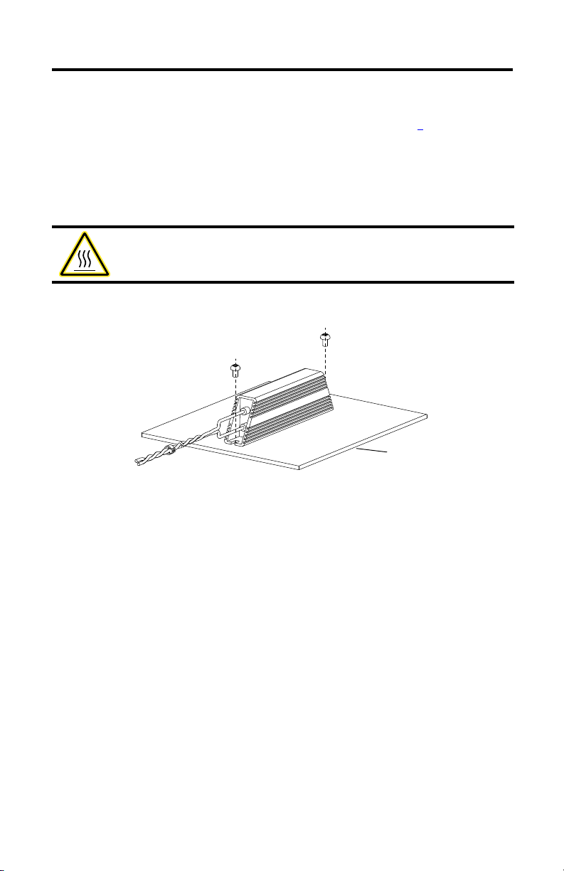
Heat Sink
Install the Shunt Resistor
Install your 2097-Rx shunt resistor by using the dimension drawing on page 4 and two
M4 (#6-32) steel machine screws. Torque to 1.1 N•m (9.8 lb•in).
The shunt resistor can operate at its full power rating if it is mounted vertically on a
200 x 200 x 3 mm (7.9 x 7.9 x 0.12 in.) heat sink at 25 ºC (77 ºF) with a clearances of 12 mm
(0.5 in.) on the sides and 50 mm (2.0 in.) above and below. If you’re not using a heat sink, refer to
the derating information in the user manual.
ATTENTION: The shunt resistor surface temperature can reach up to 200 ºC (392 ºF). Do not
touch during operation. Do not install near flammable material. We recommend that you
install in a manner that prevents user contact.
Mount Shunt Resistor to Heat Sink
Mounting holes are not equally spaced. Carefully lay out hole pattern before drilling holes in the
mounting surface.
Rockwell Automation Publication 2097-IN002E-EN-P - March 2013
Page 4

4 Bulletin 2097 Shunt Resistor
Long Flying Leads, 2.5 mm2 (14 AWG)
Shunt Resistor Dimensions
a
b
500 (19.68)
Cat. No.L1L2L3H D1
2097-R2 210 (8.3) 197 (7.7) 170 (6.7) 41 (1.6) 4.3 (0.17) 10 (0.39) 12 (0.47)
2097-R3 210 (8.3) 197 (7.7) 170 (6.7) 41 (1.6) 4.3 (0.17) 10 (0.39) 12 (0.47)
2097-R4 150 (5.9) 137 (5.4) 110 (4.3) 41 (1.6) 4.3 (0.17) 10 (0.39) 12 (0.47)
2097-R6 210 (8.3) 197 (7.7) 170 (6.7) 41 (1.6) 4.3 (0.17) 10 (0.39) 12 (0.47)
2097-R7 150 (5.9) 137 (5.4) 110 (4.3) 41 (1.6) 4.3 (0.17) 10 (0.39) 12 (0.47)
(1) D1 dimension is ± 0.3 mm (0.012 in.).
L2 ± 0.8
L3 ± 1.5
L1 ± 1.5
(1)
D1
b
a
H ± 0.5
W = a + b
ab
Rockwell Automation Publication 2097-IN002E-EN-P - March 2013
Page 5

Bulletin 2097 Shunt Resistor 5
TIP
+
+
SH
-
-
SHUNT/
DC BUS
To S hu nt
Resistor
3
2
1
Kinetix 300
Drive Shown
Wire the Shunt Resistor
The shunt resistor is wired into connector BC, a 7-pin quick-connect terminal block, which is
plugged into the Shunt/DC Bus terminal on the front of the drive. The shunt resistor connects
between the Positive DC Bus (either BC-1 or 2) and BC-4.
BC Connector Wiring Specifications
BC Pin Description Signal Strip Length Torque Value
1 and 2 Positive DC bus/shunt resistor +
7 mm (0.28 in.) 0.5 N•m (4.5 lb•in)4 Shunt resistor SH
6 and 7 Negative DC bus -
Replacement connector sets (catalog number 2097-CONN1) are available. Set includes
general purpose power input (IPD) header, back-up power (BP) header, shunt resistor and DC
bus (BC) header, motor power (MP) header, and safe torque off (STO) header.
Route shunt wires per user manual instructions. For general guidelines when laying out your
panel and mounting your shunt resistor, refer to the System Design for Control of Electrical
Noise Reference Manual, publication GMC-RM001
Shunt Resistor Terminal and Connector
Item Description
1 Front lower panel of drive
2 7-pin quick-connect terminal block
3 Shunt/DC bus connector (BC)
.
Rockwell Automation Publication 2097-IN002E-EN-P - March 2013
Page 6

6 Bulletin 2097 Shunt Resistor
Shunt Resistor Specifications
Cat. No. Resistance
2097-R2 20 150 0.29 (0.64)
2097-R3 30 150 0.29 (0.64)
2097-R4 40 80 0.19 (0.42)
2097-R6 75 150 0.29 (0.64)
2097-R7 150 80 0.19 (0.42)
Ω
Continuous Power
W
Weight, approx.
kg (lb)
Refer to the Kinetix Servo Drives Specifications Technical Data, publication GMC-TD003, for
drive and shunt resistor combinations. Use Motion Analyzer software to evaluate shunt resistor
selection. Motion Analyzer software uses your motion control profile and load requirements to
determine regeneration needs. Download Motion Analyzer software at
http://www.rockwellautomation.com/en/e-tools/configuration.html.
Rockwell Automation Publication 2097-IN002E-EN-P - March 2013
Page 7

Bulletin 2097 Shunt Resistor 7
Additional Resources
These documents contain additional information concerning related products from Rockwell
Automation.
Resource Description
Kinetix 300 EtherNet/IP Indexing Servo Drives User
Manual, publication 2097-UM001
Kinetix 350 Single-axis EtherNet/IP Servo Drives User
Manual, publication 2097-UM002
Kinetix 300 EtherNet/IP Indexing Servo Drives Installation
Instructions, publication 2097-IN001
Kinetix 350 Single-axis EtherNet/IP Servo Drives
Installation Instructions, publication 2097-IN008
Kinetix Servo Drives Specifications Technical Data,
publication GMC-TD003
Provides instructions on mounting and programming the drive and
lists technical specifications.
Provides instructions on mounting the drive and lists technica l
specifications.
Provides technical specifications for Kinetix servo drive products and
accessories.
You can view or download publications at http://www.rockwellautomation.com/literature
. To
order paper copies of technical documentation, contact your local Allen-Bradley distributor or
Rockwell Automation sales representative
Rockwell Automation Publication 2097-IN002E-EN-P - March 2013
Page 8

Rockwell Automation Support
Rockwell Automation provides tec hnical information on the Web to assist you in using its products.
At http://www.rockwellautomation.com/support
links to software service packs, and a MySupport feature that you can customize to make the best use of these tools. You can also visit
our Knowledgebase at http://www.rockwellautomation.com/knowledgebase
forums, software updates, and to sign up for product notification updates.
For an additional level of technical phone support for installation, configuration and troubleshooting, we offer TechConnect
support programs. For more information, contact your local distributor or Rockwell Automation representative, or visit
http://www.rockwellautomation.com/support/
Installation Assistance
If you experience a problem within the first 24 hours of installation, please review the information that's contained in this manual.
You can also contact a special Customer Support number for initial help in getting your product up and running.
United States or Canada 1.440.646.3434
Outside United States or
Canada
Use the Worl dwide Locato r
http://www.rockwellautomation.com/support/americas/phone_en.html
Rockwell Automation representative.
New Product Satisfaction Return
Rockwell Automation tests all of its products to help ensure that they are fully operational when shipped from the manufacturing
facility. However, if your product is not functioning and needs to be returned, follow these procedures.
, you can find technical manuals, technical and application notes, sample code and
for FAQs, technical information, support chat and
SM
.
at
, or contact your local
United States
Outside United States Please contact your local Rockwell Automation representative for the return procedure.
Contact your distributor. You must provide a Customer Support case number (call the phone number
above to obtain one) to your distributor to complete the return process.
Documentation Feedback
Your comments will help us serve your documentation needs better. If you have any suggestions on how to improve this document,
complete this form, publication RA-DU002
Allen-Bradley, Kinetix, Rockwell Software, Rockwell Automation, and TechConnect are trademarks of Rockwell Automation, Inc.
Trademarks not belonging to Rockwell Automation are property of their respective companies.
Rockwell Otomasyon Ticaret A.Ş., Kar Plaza İş Merkezi E Blok Kat:6 34752 İçerenköy, İstanbul, Tel: +90 (216) 5698400
Publication 2097-IN002E-EN-P - March 2013 PN-187134
Supersedes Publication 2097-IN002D-EN-P - November 2011 Copyright © 2013 Rockwell Automation, Inc. All rights reserved. Printed in the U.S.A.
, available at http://www.rockwellautomation.com/literature/.
 Loading...