

Page 1
Quick Start
1
4
2
3
Bulletin 2097 Memory Module Programmer
Catalog Number 2097-PGMR
Topi c Pag e
About the Memory Module Programmer 1
Parts List 3
Batteries Operation 4
Using Memory Module Programmer 6
Switch On/Off Memory Module Programmer 7
Configure the Memory Module Programmer 8
Menu Overview 10
Copy Memory Modules 11
Display Status Messages 11
Troubleshooting 13
Dimensions 14
Additional Resources 16
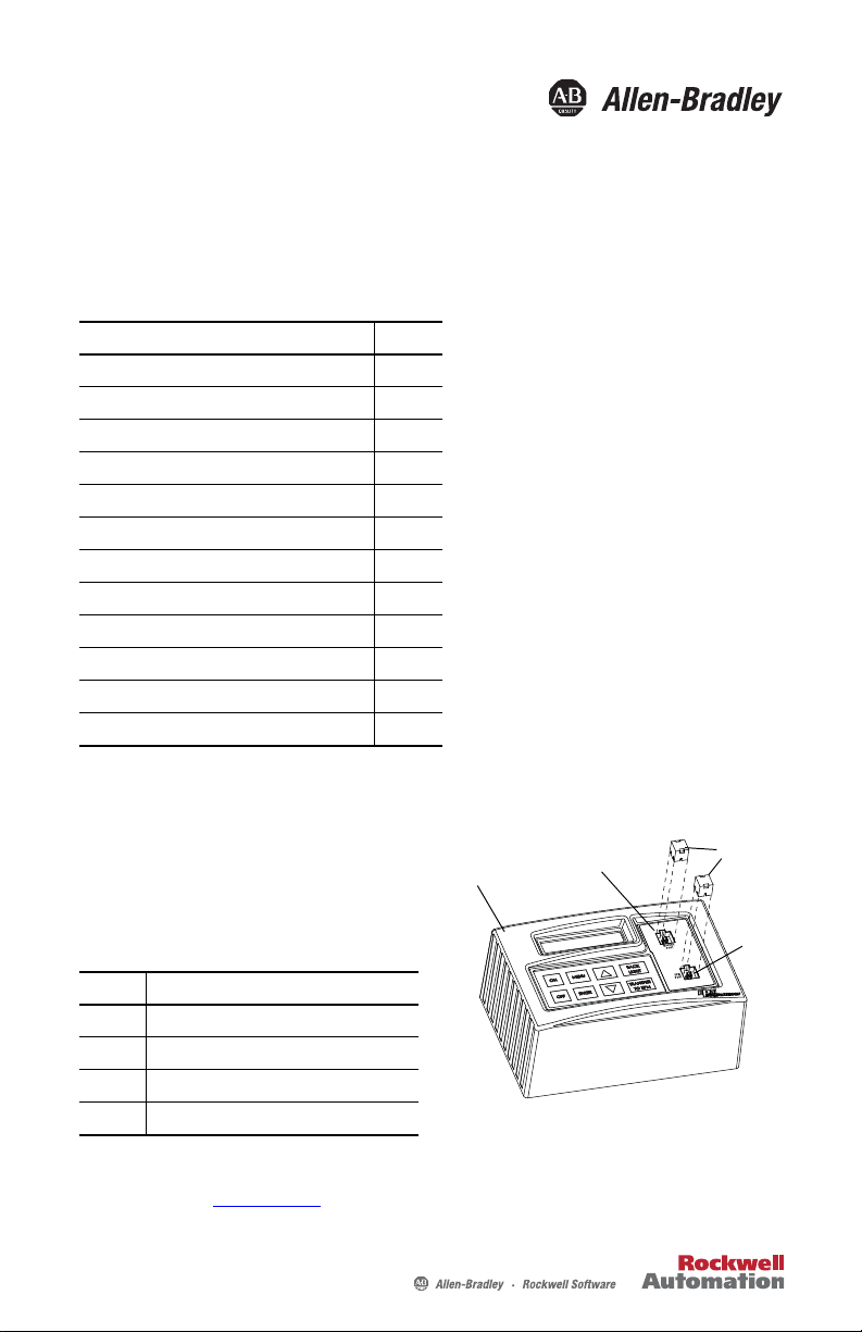
About the Memory Module Programmer
The 2097-PGMR memory module
programmer enables you to easily duplicate the
configuration of Kinetix® 300 and Kinetix 350
drives and reduces down-time and
troubleshooting.
Item Description
1 Memory module programmer
2Master port
3 EPM port
4 Bulletin 2097 memory modules, sold separately
For complete product specifications, refer to the Kinetix Servo Drives Specifications Technical
Data, publication GMC-TD003
.
Page 2
2 Bulletin 2097 Memory Module Programmer
IMPORTANT
Important User Information
Solid state equipment has operational characteristics differing from those of electromechanical equipment. Safety Guidelines for
the Application, Installation and Maintenance of Solid State Controls (Publication SGI-1.1
Automation® sales office or online at http://www.rockwellautomation.com/literatu re/
between solid state equipment and hard-wired electromechanical devices. Because of this difference, and also because of the
wide variety of uses for solid state equipment, all persons responsible for applying this equipment must satisfy themselves that
each intended application of this equipment is acceptable.
In no event will Rockwell Automation, Inc. be responsible or liable for indirect or consequential damages resulting from the use or
application of this equipment.
The examples and diagrams in this manual are included solely for illustrative purposes. Because of the many variables and
requirements associated with any particular installation, Rockwell Automation, Inc. cannot assume responsibilit y or liability for
actual use based on the examples and diagrams.
No patent liability is assumed by Rockwell Automation, Inc. with respect to use of information, circuits, equipment, or software
described in this manual.
Reproduction of the contents of this manual, in whole or in part, without written permission of Rockwell Automation, Inc., is
prohibited.
Throughout this manual, when necessary, we use notes to make you aware of safety considerations.
WARNING: Identifies information about practices or circumstances that can cause an explosion in a
hazardous environment, which may lead to personal injury or death, property damage, or economic loss.
available from your local Rockwell
) describes some important differences
ATTENTION: Identifies information about practices or circumstances that can lead to personal injury or
death, property damage, or economic loss. Attentions help you identify a hazard, avoid a hazard and
recognize the consequences.
SHOCK HAZARD: Labels may be on or inside the equipment, for example, a drive or motor to alert people
that dangerous voltage may be present.
BURN HAZARD: Labels may be on or inside the equipment, for example, drive or motor to alert people that
surfaces may reach dangerous temperatures.
Identifies information that is critical for successful application and understanding of the product.
Publication 2097-QS001D-EN-P - November 2011
Page 3
Bulletin 2097 Memory Module Programmer 3
1
23
Before You Begin
Before programming your 2097-MEM module by using the 2097-PGMR memory module
programmer, read this quick start carefully and follow all the instructions.
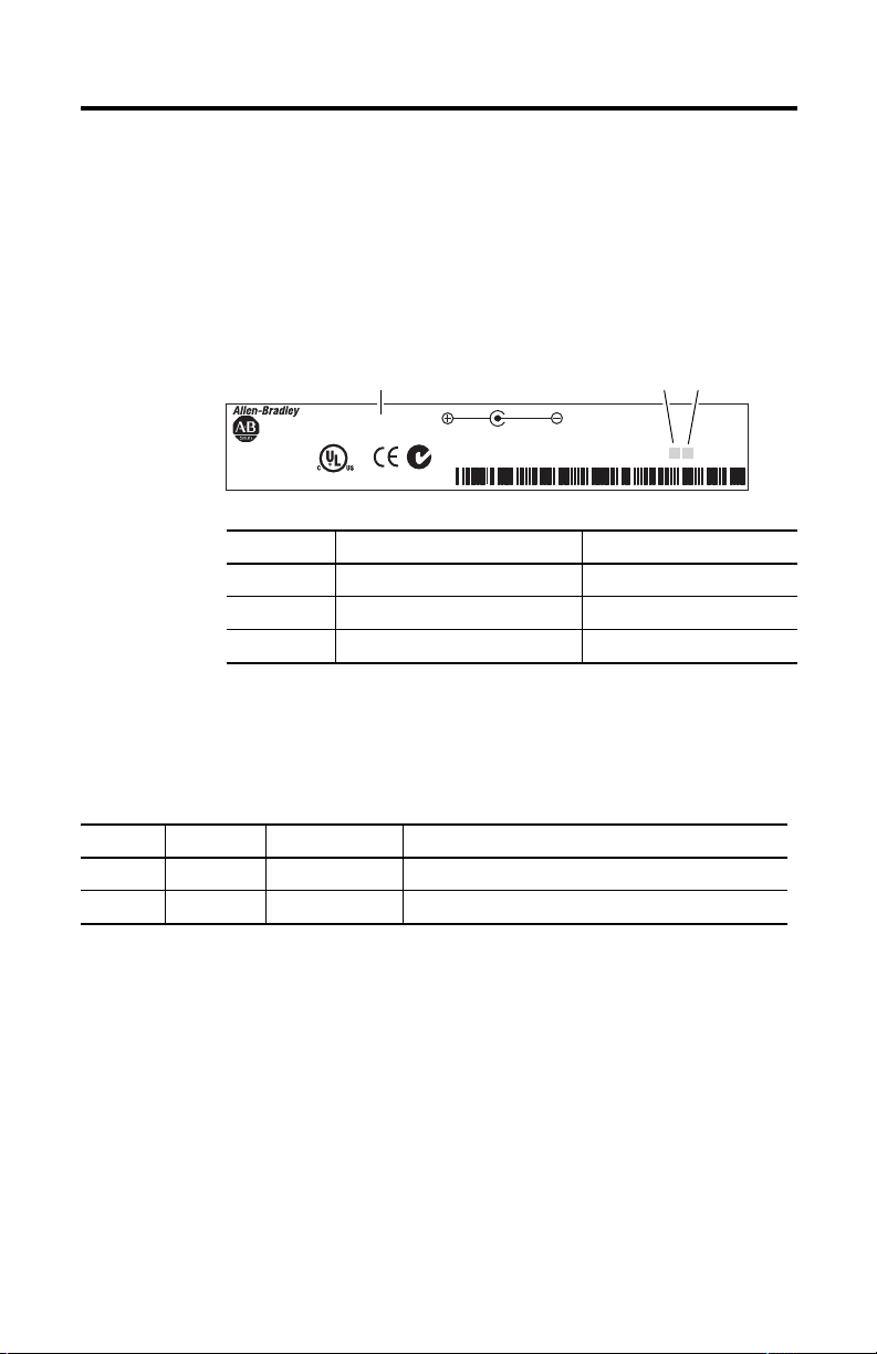
Hardware Requirements
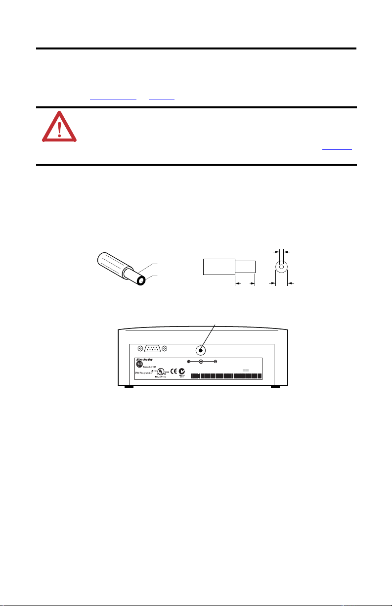
This documentation applies to the memory module programmer version 1A 10. The
identification label is on the back of the memory module programmer.
For detailed information
Product of USA
EPM Programmer
CAT. NO. 2097-PGMR
LISTED
CONT EQ
IND.
5D81
6V DC 150 mA min
Power Supply
(FRIWO 7207/06 1.0791 MPP15)
N10104
Z519
Item Description Value
1 Catalog number 2097-PGMR
2 Hardware revision 1A
3Software version 10
refer to instruction
manual
SN: 2097-PGMR012345678
HW/SW REV:1A 10
Parts List
The following items come with the memory module programmer.
Quantity Cat. No. Publication No. Description
1 2097-PRGM — Memory module programmer with 4 batteries installed.
1 — 2097-QS001 Memory module programmer quick start.
Inspect the memory module programmer and verify that it is damage free. Any damage or
suspected damage should be immediately documented. Claims for damage due to shipment are
usually made against the transportation company. Contact Rockwell Automation for further
advice:
• Compare the purchase order with the packing slip.
• Check that the quantity of memory modules received matches your job requirements.
Memory modules are ordered separately.
Publication 2097-QS001D-EN-P - November 2011
Page 4
4 Bulletin 2097 Memory Module Programmer
Pb
Power Supplies
The memory module programmer ships with 4 (1.5V mono-cells) batteries preinstalled, and is
ready for use. It can also be operated with an external power supply.
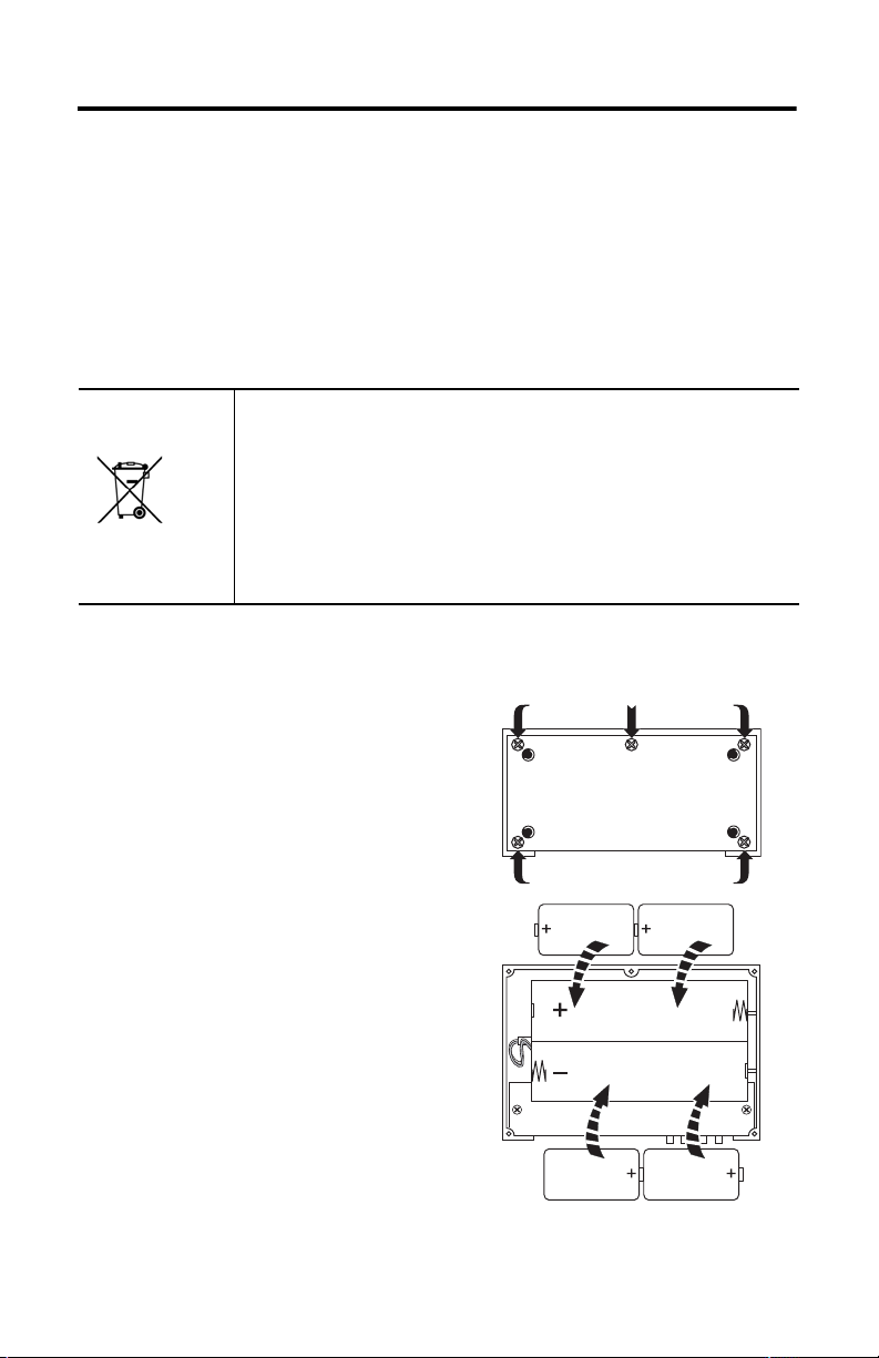
Batteries Operation
For battery operation, you need 4 mono-cell (D size) with 1.5V each. To access the battery
compartment, open the housing on the bottom of memory module programmer.
ATT EN TIO N: This product contains a sealed lead acid battery which may need to be
replaced during the life of the product.
At the end of its life, the battery contained in this product should be collected
separately from any unsorted municipal waste. The ‘Pb’ symbol indicates the presence
of lead.
The collection and recycling of batteries helps protect the environment and
contributes to the conservation of natural resources as valuable materials are
recovered.
Battery Replacement
1. Remove the five screws and base plate.
2. Insert the batteries following correct
polarity.
3. Replace the base plate and secure with the
five screws.
Publication 2097-QS001D-EN-P - November 2011
Page 5
Bulletin 2097 Memory Module Programmer 5
TIP
+6V DC
–
9.5
(0.37)
5.5
(0.22)
2.1
(0.08)
Dimensions are in mm (in.).
CAT. NO. 2097-PGMR
For detailed information
refer to instruction
manual
HW/SW REV:1A 10
SN: 2097-PGMR012345678
6V DC 150 mA min
Power Supply
(FRIWO 7207/06 1.0791 MPP15)
External Power Supply Connector
Operation with External Power Supply
You can operate the memory module programmer with a customer-supplied external power
supply. Refer to Specifications
ATTENTION: The memory module programmer contains electrostatic discharge (ESD) sensitive
parts and assemblies. You are required to follow static-control precautions when you use it. If you
do not follow ESD control procedures, components can be damaged. If you are not familiar with
static control procedures, refer to Guarding Against Electrostatic Damage, publication 8000-4.5.2
or any other applicable ESD awareness handbook.
You can remedy occasional memory module programmer anomalies by turning it off and on.
To use the memory module programmer with your external power supply, the power supply
requires an extra-low voltage plug with the following dimensions.
on page 15 for power supply requirements.
,
Publication 2097-QS001D-EN-P - November 2011
Page 6

6 Bulletin 2097 Memory Module Programmer
OFF ENTER
ON MENU
BACK
LIGHT
COPY
TO EPM
12
34
ENTER
Using Memory Module Programmer
.
Key Functions
Key Level Function
Item Description Function
1 Display Command st atus.
2Master port
Plug-in-station for memory
module from which the data is
to be read.
Plug-in-station for memory
3 EPM port
Operator
4
keypad
module memory chip on
which the data is to be
written.
Comma nd entry.
ON
OFF
Menu Select menu, quit submenu
MENU
Param eter
Menu Select subm enu, execute menu command
Param eter
Menu Select subm enu/file
Param eter
Menu Select subm enu/file
Parameter Enter a lower value
BACK
LIGHT
COPY
TO EPM
Publication 2097-QS001D-EN-P - November 2011
Switch on memory module programmer
Switch off memory module programmer
Return to the main menu without saving changes
Select parameter to enter a value, accept a value entered
Enter a higher value
Switch on/off background illumination for the display
Copy data to EPM port
Page 7

Bulletin 2097 Memory Module Programmer 7
TIP
TIP
Switch On/Off Memory Module Programmer
Switch On
Step Display
ON
Press .
The following is displayed in sequence.
The parameter version that the memory module programmer is configured with (for example,
400) is displayed.
The parameter version of the memory modul e (for example, 400) plugged into the master port
is displayed.
The name of the parameter file (for example, DEFAULTS) stored in the memory module plugged
into the master port is displayed.
If no memory module is plugged into the master port, this message is displayed. MASTER MISSING!
After the initialization, the main menu shown last is automatically called up.
Switch Off
Step Displayed
OFF
Press .
The shutdown process takes 5 seconds.
If you press any key within these 5 seconds, the shutdown process is aborted.
EPM PROGRAMMER
INTERN CFG 400
MASTER CFG 400
MSTFILE#DEFAULTS
SHUTDOWN.. 5SEC
The memory module programmer automatically turns off after 5 minutes, if no operation
takes place during this time.
Publication 2097-QS001D-EN-P - November 2011
Page 8

8 Bulletin 2097 Memory Module Programmer
TIP
Configure the Memory Module Programmer
Although several menus may be displayed, the configuration of the memory module program is
limited to background illumination and display contrast. The function for language selection is
limited to English and setting the password has no effect on functions available for the Bulletin
2097 memory module.
Switch On/Off Display Background Illumination
Step Display
BACK
LIGHT
1. Press .
The background illumination is switched on.
BACK
LIGHT
2. Press .
The background illumination is switched off.
If you operate the memory module programmer with a power supply unit, the background
illumination will always be switched on.
Publication 2097-QS001D-EN-P - November 2011
Page 9

Bulletin 2097 Memory Module Programmer 9
MENU
MENU
Contrast Setting
With this function, you can adjust the viewing angle for the memory module programmer
display.
Step Display
1. Press until the DISPLAY CONTRAST menu appears in the display.
ENTER
2. Press .
The currently set value is indicated, for example, MEDIUM.
ENTER
3. Press .
The cursor is blinking in the display on the right.
4. Use to select the desired setting.
ENTER
5. Press .
The setting selected, for example LOW, is accepted. The cursor stops blinking.
6. Press .
Returns to the main menu.
DISPLAY CONTRAST
CONTR AST MEDIU M
CONTR AST MEDIU M
CONTR AST LOW
CONTR AST MEDIU M
CONTR AST HIGH
CONTR AST LOW
DISPLAY CONTRAST
Publication 2097-QS001D-EN-P - November 2011
Page 10

10 Bulletin 2097 Memory Module Programmer
TIP
MENU
MENU
MENU
MENU
MENU
MENU
MENU
MENU
MENU
MASTER -> EPM
FILE -> EPM
EDIT EPM
EDIT FILE
CREATE NEW FILE
DELETE FILE
LOAD CFG EPM
MISCELLANEOUS
DISPLAY CONTRAST
See page
11.
See page
11.
See page
9.
Not available for
memory module.
Not available for
memory module.
Not available for
memory module.
Not available for
memory module.
Not available for
memory module.
Not available for
memory module.
Menu Overview
After power is switched on and the initialization screens have been displayed, the primary
functions of the memory module programmer are accessed by pressing . The programmer
has many menus and functions that are accessible, however most functions do not work on the
memory modules used with the Kinetix 300 or Kinetix 350 drives.
MENU
When copying to a memory module by using MASTER->EPM, all data on the target memory
Publication 2097-QS001D-EN-P - November 2011
module will be overwritten.
Page 11

Bulletin 2097 Memory Module Programmer 11
MENU
COPY
TO EPM
ENTER
MENU
MENU
Copy Memory Modules
With this function, it is possible to copy a parameter file directly from one memory module, a
Master, to another memory module.
Step Display
1. Plug the memory module containing the parameter file you want to copy into the master port. –
2. Plug the mem ory module, to which you want to copy the parameter file, into the EPM por t. –
3. Press until MASTER –> EPM appears in the display.
MASTER –> EPM
ENTER
4. Press .
The name of the parameter file (for example, DEFAULTS) of the memory module in the master
#DEFAULTS(400)>>
port is displayed. The parameter version of the file is shown in parenthesis.
5. Press .
The parameter file is copied.
The parameter version of the file does not correspond with the parameter version of the
memory module in the EPM port.
TRANSFERRING 0%
DAT=400 EPM=312
CONFIRM= [ENTER]
A security check takes place concerning the existing data on the memory m odule.
6. Press to overwrite the existing data or press , if you want to abort the process.
ENTER
7. Press .
MENU
The parameter file will be copied.
8. Press .
–
TRANSFERRING 100%
#DEFAULTS(400)>>
MASTER –> EPM
Returns to the main menu.
Display Status Messages
With this function, you can view important information about the memory module
programmer.
Step Display
1. Press until the MISCELLANEOUS menu appears in the display.
ENTER
2. Press to access the submenu.
The software vers ion of the
For example, 1.00.
memory module programmer is displayed.
3. Press to select the status messages.
MISCELLANEOUS
S/W VERSION X.XX
–
Publication 2097-QS001D-EN-P - November 2011
Page 12

12 Bulletin 2097 Memory Module Programmer
Step Display
4. Press .
Shows the parameter version that the memory module programmer is configured for.
For example, 4 00.
5. Press .
This function is not available for Bulletin 2097 memory module s.
6. Press .
The current voltage level of the four internal batteries is displayed. To guarantee safe operation,
the battery voltage must not fall below 3.6V DC.
7. Press .
The set password for the access protection (factory setting: 0000) is displayed. Entering and
changing has no effect on the use of Bulletin 2097 memory modules.
MENU
8. Press .
Returns to the main menu.
INTERN CFG 400
F ILES: 1
BATTERY: 5.8VDC
PASSWORD: 0000
MISCELLANEOUS
Publication 2097-QS001D-EN-P - November 2011
Page 13

Bulletin 2097 Memory Module Programmer 13
Troubleshooting
Troubleshooting
Description Possible Cause Corrective Action
CHANGE BATTERY! The battery voltage is <3.6V. This message is
FILE VER INCOMP! Attempted to edit a memory module. Function not available.
READ ONLY FILE! You have tried to edit or delete a file. Function not available.
EPM DAMAGED! The memory module in the EPM port is
EPM MISSING! There is no memory module in the EPM port to
EPM TOO SMALL! The memory module in the EPM port does not
INTERNAL ERROR! Internal device error. Contact your Rockwell Automation
INVALID INT CFG Attempting to reconfigure the memory module
WRONG PASSWORD Password protection is activated and you have
MASTER DAMAGED! The memory module in the master port is
MASTER MISSING Seen on powerup if there is no memory module
INVALID MASTER! The memory module you are attempting to
NAME EXISTS! Defective memory module programmer. Contact Rockwell Automation Technical
MEMORY FULL The internal memory of the memory module
displayed after switching on the memory
module programmer.
defective.
The memory module is not placed correctly in
the EPM port.
which you are attempting to transfer data or
edit.
have sufficient memory for the file you are
attempting to co py.
programmer.
entered the wrong password after switch-on.
defective.
The memory module is not placed correctly in
the master port.
in the master port.
Programmer is trying to read data from the
master port but cannot detect a memory
module in this port.
read in the master port is defective or has no
valid data.
programmer is full.
Change the batteries; see page 4.
Contact Rockwell Automation technical support
or exchange the defective memory module.
Plug the memory module correctly in the port.
Press Menu now to return to the main menu.
Plug a memory module in the EPM port.
Contact Rockwell Automation technical
support.
representative.
Function not available.
The password function has no affect on the
ability to duplicate Bulletin 2097 memor y
modules. No action is required.
Press Menu to return to the main menu. Plug a
memory module in the master port.
The message does not indicate an error but only
serves as a note.
The message is displayed only for a short time.
Information only.
Insert a valid memory module into the master
port.
Press Menu now to return to the main menu.
Exchange the memory module in the master
port.
Support.
Contact Rockwell Automation Technical
Support.
Publication 2097-QS001D-EN-P - November 2011
Page 14

14 Bulletin 2097 Memory Module Programmer
COPY
105
(4.1)
76
(3.0)
155
(6.1)
4
(0.16)
Dimension are in mm (in.).
Troubleshooting (continued)
Description Possible Cause Corrective Action
TRANSFER FAILED Error in the data transmission to the EPM port,
INVALID OPTION! Attempted to create a new file from a servo
INVALID EPM! Attempted to edit a memory module. Function not available.
NO FILES Attempting to edit, delete, or create a file, but
CFG EPM MISSING! Attempted to LOAD CFG EPM. Function not available.
because the memory chip is defec tive, or is not
placed correctly in the port.
Attempted MASTER -> EPM transfer when the
memory size of the master memory module is
different from that of the target.
Error in the data transmission to the EPM port,
because of an internal error in the memory
module programmer.
drive memory module in the master port.
there are no stored files in the memory module
programmer.
Exchange the defective memory module or plug
the memory module correctly in the port.
Replace the memory module in the EPM port
with a memory module of the same color as the
master.
Contact your Rockwell Automation
representative.
Function not available.
Function not available.
Dimensions
Publication 2097-QS001D-EN-P - November 2011
Page 15

Bulletin 2097 Memory Module Programmer 15
Specifications
Technical Specifications -Catalog Number 2097-PRGM
Attribute 2097-PRGM
DC voltage supply 6V DC, 150 mA min
Internal batteries 4 mono-cells (type D), 1.5V DC each
External power supply unit 6V DC, 300 mA, stabil ized
Display Type LCD
Display format Text
Lines x characters 1 x 16
Contrast setting Via menu
Memory Data memory Up to 120 parameter files for inverter drive controllers
Serial interface DB9 connector RS232
Environmental Specifications - Catalog Number 2097-PRGM
Attribute 2097-PRGM
Type of protection IP20
Permissible temperature ratings Operation 0…50 °C (32…122 °F)
Humidity <85%, without condensation
Weight, approx. 1.3 kg (2.87 lb), with batteries
Applied standards Noise emission to EN 50081-2: 1993
Approvals UL 508C Underwriters Laboratories
Conformity CE EMC Directive (89/336/CEE)
Transport -20…60 °C (-4…140 °F)
Storage -20…60 °C (-4…140 °F)
Noise immunity to EN 61000-6-2: 1999
Power Conversion Equipment
Publication 2097-QS001D-EN-P - November 2011
Page 16

Additional Resources
These documents contain additional information concerning related products from Rockwell
Automaiton.
Resource Description
Kinetix 300 EtherNet/IP Indexing Servo Drives User
Manual, publication 2097-UM001
Kinetix 350 Single-axis EtherNet/IP Ser vo Drives User
Manual, publication 2097-UM002
Kinetix 300 EtherNet/IP Indexing Servo Drives
Installation Instructions, publication 2097-IN001
Kinetix 350 Single-axis EtherNet/IP Ser vo Drives
Installation Instructions, publication 2097-IN008
Kinetix 300 Memory Module Installation Instruc tions,
publication 2097-IN007
Provides instructions on mounting and programming the drive and lists
technical specifications.
Provides instructions on mounting the drive and lists technical
specifications.
Provides diagrams on how to install and remove the memory module in
the drive.
You can view or download publications at http://www.rockwellautomation.com/literature
. To
order paper copies of technical documentation, contact your local Allen-Bradley® distributor or
Rockwell Automation sales representative.
Allen-Bradley, Kinetix, Rockwell Software, and Rockwell Automation are trademarks of Rockwell Automation, Inc.
Trademarks not belonging to Rockwell Automation are property of their respective companies.
Publication 2097-QS001D-EN-P - November 2011 PN-124738
Supersedes Publication 2097-QS001C-EN-P - June 2010 Copyright © 2011 Rockwell Automation, Inc. All rights reserved. Printed in the U.S.A.
 Loading...