

Page 1
Installation Instructions
Bulletin 2097 AC Line Filters
Catalog Numbers 2097-F1, 2097-F2, 2097-F4, 2097-F5, 2097-F6
Topi c Pag e
About the AC Line Filters 1
Important User Information 2
Before You Begin 3
Install the AC Line Filter (side-mount) 4
Install the AC Line Filter (rear-mount) 5
Bulletin 2097 AC Line Filter Specifications 8
Additional Resources 8
About the AC Line Filters
This publication provides installation instructions for the Bulletin 2097 AC Line Filters. The
2097-Fx AC Line Filters apply to Kinetix 300 and Kinetix 350 servo drives. Use these
instructions for installing and wiring your AC Line Filter. For more information refer to the user
manual available for your drive listed in Additional Resources
on page 8.
Page 2
2 Bulletin 2097 AC Line Filters
IMPORTANT
Important User Information
Solid state equipment has operational characteristics differing from those of electromechanical equipment. Safety
Guidelines for the Application, Installation and Maintenance of Solid State Controls (Publication SGI-1.1
local Rockwell Automation® sales office or online at http://ww w.rockwellautomation.com/literature/
important differences between solid state equipment and hard-wired elec tromechanical devices. Because of this difference,
and also because of the wide variety of uses for solid state equipment, all persons responsible for applying this equipment
must satisfy themselves that each intended application of this equipment is a cceptable.
In no event will Rockwell Automation, Inc. be responsible or liable for indirect or consequential damages resulting from the
use or application of this equipment.
The examples and diagrams in this manual are included solely for illustrative purposes. Because of the many variables and
requirements associated with any particular installation, Rockwell Automation, Inc. cannot assume responsibility or liability
for actual use based on the examples and diagrams.
No patent liability is assumed by Rockwell Automation, Inc. with respect to use of information, circuits, equipment, or
software described in this manual.
Reproduction of the contents of this manual, in whole or in part, without written permission of Rockwell Automation, Inc., is
prohibited.
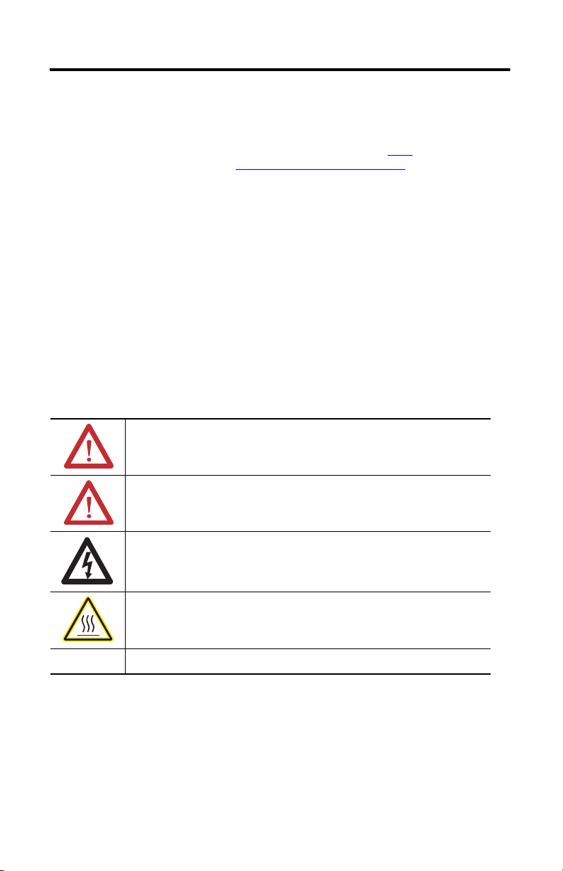
Throughout this manual, when necessary, we use notes to make you aware of safety considerations.
WARNIN G: Identifies information about practices or circumstances that can cause an explosion in a
hazardous environment, which may lead to personal injury or death, property damage, or economic
loss.
available from your
) describes some
ATTENTION: Identifies information about practices or circumstances that can lead to personal injur y or
death, property damage, or economic loss. Attentions help you identify a hazard, avoid a hazard and
recognize the consequences.
SHOCK HAZARD: Labels may be on or inside the equipment, for exa mple, drive or motor to alert
people that dangerous voltage may be present.
BURN HAZARD: Labels may be on or inside the equipment, for exampl e, drive or motor to alert
people that surfaces may reach dangerous temperatures.
Identifies information that is critical for successful application and understanding of the product.
Publication 2097-IN003D-EN-P - November 2011
Page 3

Bulletin 2097 AC Line Filters 3
Before You Begin
For general guidelines when laying out your panel and mounting your AC line filter, refer to the
System Design for Control of Electrical Noise Reference Manual, publication GMC-RM001.
For guidelines specific to your application, refer to Additional Resources
manual.
ATTENTION: To avoid personal injury or damage to equipment due to hazardous voltages, follow
these guidelines when installing your AC line filter. NEC and local regulations always take
precedence.
• Disconnect mains power prior to installation.
• Verify that the rated voltage is compatible with the local supply voltage.
• Connect the earth ground connection first when making connections.
page 8 for the user
Publication 2097-IN003D-EN-P - November 2011
Page 4

4 Bulletin 2097 AC Line Filters
Input Power
Install the AC Line Filter (side-mount)
The following steps apply to the installation of AC line filter, catalog numbers 2097-F1 and
2097-F2.
1. Use Fig ure 2 on pag e 7
install your side-mount AC line filter.
Adjust drive location as necessary.
2. Mount the AC line filter to the drive with two M4 x 0.7 steel machine screws and torque
to 1.1 N•m (9.8 lb•in).
3. Mount drive and filter assembly to the cabinet panel by using three M4 x 0.7 steel
machine screws and torque to 1.1 N•m (9.8 lb•in).
to determine the space required on the right side of your drive to
Publication 2097-IN003D-EN-P - November 2011
Page 5

Bulletin 2097 AC Line Filters 5
Input Power
Install the AC Line Filter (rear-mount)
The following steps apply to the installation of your AC line filter, catalog numbers 2097-F4,
2097-F5, and 2097-F6.
1. Use Fig ure 3 on pag e 7
rear-mount AC line filter.
Rear-mount AC line filters require additional cabinet depth; adjust cabinet as necessary.
2. Mount the AC line filter to the panel with three M4 x 0.7 steel machine screws and
torque to 1.1 N•m (9.8 lb•in).
3. Mount the drive to the AC line filter with three M4 x 0.7 steel machine screws and
torque to 1.1 N•m (9.8 lb•in).
to determine the cabinet space required to install your
4. Mount the drive and AC line filter assembly on the panel.
Publication 2097-IN003D-EN-P - November 2011
Page 6

6 Bulletin 2097 AC Line Filters
TIP
Bonded Cabinet
Ground Bar
AC Line Fi lters
Input Fusing
Line, AC Mains
Kinetix 300 Drive
Input Power (IPD)
Connecti ons
Line Load
Ground Terminals
Wire the AC Line Filter
Connect the AC line filter as shown in these examples. Refer to the System Design for Control
of Electrical Noise Reference Manual, publication GMC-RM001, for proper high-frequency
(HF) bonding techniques to improve overall system performance.
Replacement connector sets (catalog number 2097-CONN1) are available. Sets include
general purpose power input (IPD) header, back-up power (BP) header, shunt resistor and DC
bus (BC) header, motor power (MP) header, and safe torque off (STO) header.
Figure 1 Wiring Example for the AC Line Filter
IPD Connector Wiring Specifications
Cat. No. Input Power
2097-F1
2097-F2
2097-F4
2097-F5
2097-F6
240/480V AC
IPD-4 (L3)
IPD-3 (L2)
IPD-2 (L1)
IPD-1 (PE)
Connects to Terminals
Pin Signal
IPD-1
IPD-2
IPD-3
IPD-4
PE
L1
L2
L3
240/480V
Recommended
Wire Size mm2 (AWG)
14 AWG (2.5mm
L3’
L2’
L1’
PE
2
L3
L2
L1
Strip Length
mm (in.)
) 7 (0.28) 0.5 (4.5)
Torq ue Val ue
N•m (lb•in)
Publication 2097-IN003D-EN-P - November 2011
Page 7

Bulletin 2097 AC Line Filters 7
Dimension are in mm (in.).
This connector comes prewired to
the AC line filter.
4.1
(0.16)
219.1
(8.62)
4.6 ø
(0.18)
4.6
(0.18)
68.6
(2.70)
48.0
(1.89)
38.1
(1.50)
15.2
(0.60)
211.0
(8.31)
Dimension are in mm (in.).
This connec tor comes prewired to
the AC line filter.
AC Line Filter Dimensions
Mounting dimensions for side and rear-mount AC line filters.
Figure 2 AC Line Filter (side-mount) Dimensions Catalog Numbers 2097-F1 and 2097-F2
165.6
(6.52)
149.9
(5.90)
33 0
(1.30)
35.8
(1.41)
Figure 3 AC Line Filter (rear-mount) Dimension Catalog Numbers 2097-F4, 2097-F5, and
2097-F6
Publication 2097-IN003D-EN-P - November 2011
Page 8

Bulletin 2097 AC Line Filter Specifications
Cat. No. Installation Current A Weight, approx kg (lb)
2097-F1 Side-mount 24.0 0.6 (0.13)
2097-F2 Side-mount 10.0 0.6 (0.13)
2097-F4 Rear-mount 4.4 0.8 (0.18)
2097-F5 Rear-mount 6.9 0.8 (0.18)
2097-F6 Rear-mount 15.0 0.8 (0.18)
Additional Resources
These documents contain additional information concerning related products from Rockwell
Automation.
Resource Description
Kinetix 300 EtherNet/IP Indexing Servo Drives User Manual,
publication 2097-UM001
Kinetix 350 Single-axis EtherNet/IP Ser vo Drives User Manual,
publication 2097-UM002
Kinetix 300 EtherNet/IP Indexing Servo Drives Installation
Instructions, publication 2097-IN001
Kinetix 350 Single-axis EtherNet/IP Ser vo Drives Installation
Instructions, publication 2097-IN008
Kinetix Servo Drives Specifications Technical Data, publication
GMC-TD003
Provides instructions on mounting and programming the
drive and lists technical specifications.
Provides instructions on mounting the drive and lists
technical specifications.
Provides techinal specifications for Kinetic servo drive
products and accessories.
You can view or download publications at http://www.rockwellautomation.com/literature. To
order paper copies of technical documentation, contact your local Allen-Bradley® distributor or
Rockwell Automation sales representative.
Allen-Bradley, Kinetix, Rockwell Software, and Rockwell Automation are trademarks of Rockwell Automation, Inc.
Trademarks not belonging to Rockwell Automation are property of their respective companies.
Publication 2097-IN003D-EN-P - November 2011 PN-124734
Supersedes Publication 2097-IN003C-EN-P - June 2010 Copyright © 2011 Rockwell Automation, Inc. All rights reserved. Printed in the U.S.A.
 Loading...