

Page 1

Installation Instructions
Kinetix 6000M Integrated Drive-Motor Power Interface Module
Catalog Number
Topi c Pag e
Important User Information 2
Catalog Number Explanation 3
Before You Begin 4
Install the IPIM Module 4
Determining Mounting Order 5
Feature and Connector Identification 8
Wirin g 9
Dimensions 12
Additional Resources 13
2094-SEPM-B24-S
About the Integrated Drive-Motor Power Interface Module
The Kinetix® 6000M Integrated Drive-Motor (IDM) system uses the 2094-SEPM-B24-S IDM
Power Interface Module (IPIM) to connect IDM units to 400V-class Kinetix 6000 or
Kinetix 6200 multi-axis drive systems. The IDM Power Interface Module occupies a single slot
on Kinetix 6000 power rails.
The IDM system is controlled by a real-time sercos II network. The sercos II fiber-optic cables
connect to the IPIM module, which passes real time data to the IDM units by a daisy chained
network cable. A network terminator is required at the last IDM unit.
A hybrid cable provides a means to pass inter-module communication signals and power to each
IDM unit. The network cable and hybrid cable are daisy chained from one IDM unit to another,
with a terminator required at the last IDM unit (see IPIM and IDM Interconnect
Up to 16 IDM units may be daisy chained to an IPIM module (depending on load conditions).
Terminator connectors for the hybrid and network connections are included with each IPIM.
on page 3).
Mount the IPIM module on the power rail in order of decreasing power utilization. See
Determining Mounting Order
Refer to the Kinetix 6000M Integrated Drive-Motor System User Manual, publication
2094-UM003
integration with ControlLogix®, CompactLogix™, or SoftLogix™ controller platforms.
, for detailed information on wiring, applying power, troubleshooting, and
on page 5 for detailed information.
Page 2
2 Kinetix 6000M Integrated Drive-Motor Power Interface Module
Important User Information
Solid-state equipment has operational characteristics differing from those of electromechanical equipment. Safety Guidelines for the
Application, Installation and Maintenance of Solid State Controls (publi cation SGI-1.1
sales office or online at http://www.rockwellautomation.com/literature/
equipment and hard-wired electromechanical devices. Because of this difference, and also because of the wide variety of uses for
solid-state equipment, all persons responsible for applying this equipment must satisfy themselves that each intended application of
this equipment is acceptable.
In no event will Rockwell Automation, Inc. be responsible or liable for indirect or consequential damages resulting from the use or
application of this equipment.
The examples and diagrams in this manual are included solely for illustrative purposes. Because of the many variables and
requirements associated with any particular installation, Rockwell Automation, Inc. cannot assume responsibility or liability for actual
use based on the examples and diagrams.
No patent liability is assumed by Rockwell Automation, Inc. with respect to use of information, circuits, equipment, or software
described in this manual.
Reproduction of the contents of this manual, in whole or in part, without written permission of Rockwell Automation, Inc., is
prohibited.
Throughout this manual, when necessary, we use notes to make you aware of safety considerations.
WARNIN G: Identifies information about practices or circumstances that can cause an explosion in a hazardous
environment, which may lead to personal injury or death, property damage, or economic loss.
available from your local Rockwell Automation®
) describes some important differences between solid-state
ATTENTION: Identifies information about practices or circumstances that can lead to personal injury or death,
property damage, or economic loss. Attentions help you identify a hazard, avoid a hazard and recognize the
consequences.
SHOCK HAZARD: Labels may be on or inside the equipment, for example, a drive or motor, to alert people that
dangerous voltage may be present.
BURN HAZARD: Labels may be on or inside the equipment, for example, a drive or motor, to alert people that
surfaces may reach dangerous temperatures.
IMPORTANT Identifies information that is critical for successful application and understanding of the product.
Publication 2094-IN016A-EN-P - February 2012
Page 3
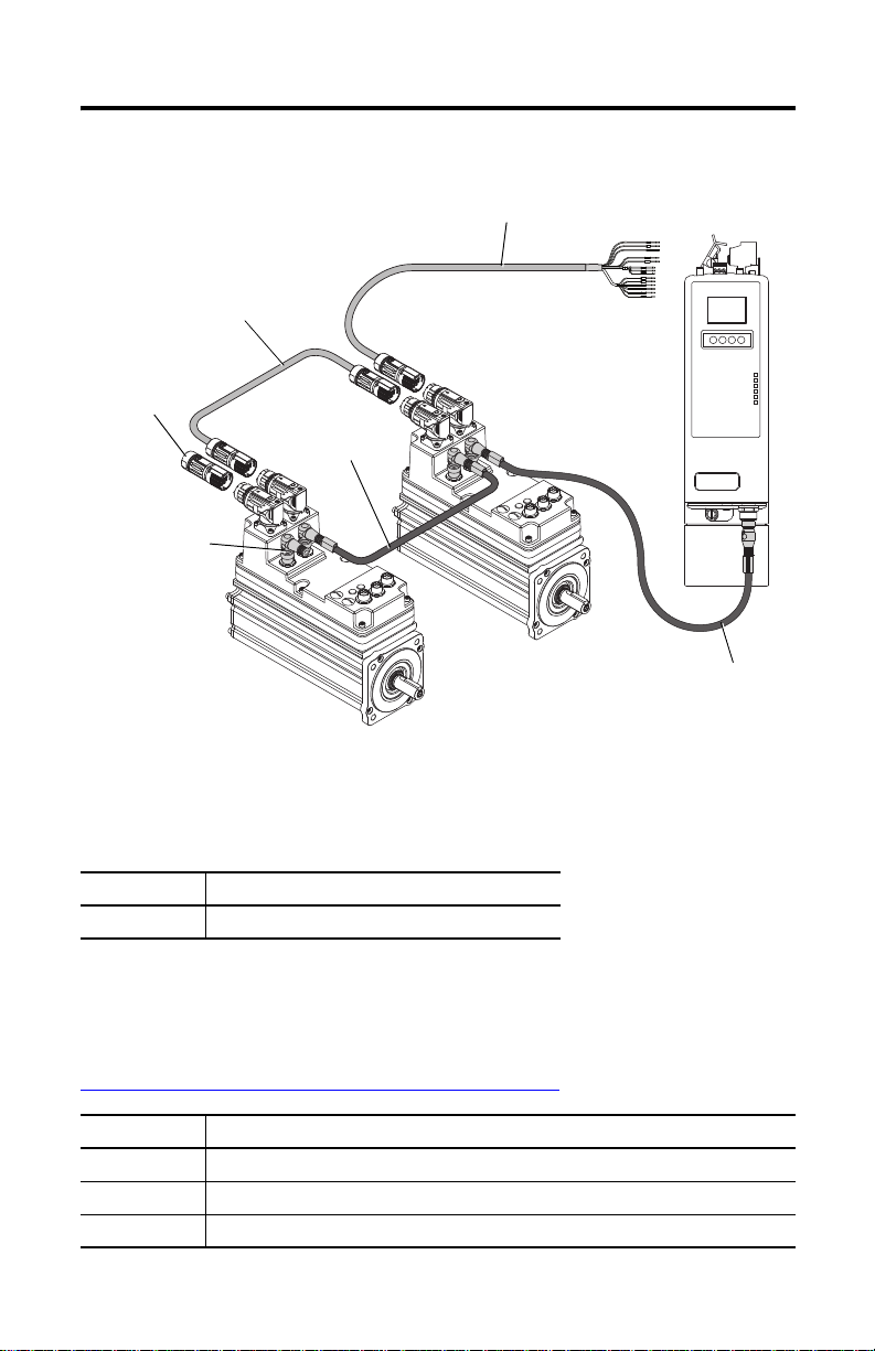
IPIM and IDM Interconnect
PORT 1 PORT 2 NETWORK
IDM to IDM Hybrid Cable
(2090-CHBP8S8-12AAxx)
IPIM Module
IDM Unit
IDM Unit
Network Terminator
Last IDM Unit
(2090-CTSRP)
Network Cable
(2090-CNSRPRS-AAxx)
Network Cable to First
IDM
(2090-CNSSPRS-AAxx)
Hybrid Terminator
Last IDM Unit
(2090-CTHP8)
IPIM to IDM Hybrid Cable
(2090-CHBIFS8-12AAxx)
(Catalog numbers are in parenthesis.)
Kinetix 6000M Integrated Drive-Motor Power Interface Module 3
Catalog Number Explanation
This publication applies to the following Kinetix 6000M system component.
Cat. No. Description
2094-SEPM-B24-S 400V-class IDM Power Interface Module with sercos interface
Software and Firmware Requirements
You must have this version of software/firmware, which can be downloaded from:
http://www.rockwellautomation.com/support/downloads.html
Product Version
RSLogix™ 5000 20.00 or later. If you are using version 20.00, you need version 1.x of the add-on profile.
Kinetix 6000 1.123 or later
Kinetix 6200 1.045 or later
Publication 2094-IN016A-EN-P - February 2012
Page 4
4 Kinetix 6000M Integrated Drive-Motor Power Interface Module
Before You Begin
Remove all packing material, wedges, and braces from within and around the components. After
unpacking, check the item nameplate catalog number against the purchase order.
Parts List
Component Ships with
IPIM module • Wiring plug connector set for DC bus, enable, and hybrid power/communication
• Wiring plug header and motion-allowed jumper for safe-off connector
• A 2090-CTHP8 hybrid terminator and 2090-CTSRP network terminator
• These installation instructions, publication 2094-IN016
Install the IPIM Module
This procedure assumes you have prepared your panel, mounted your Bulletin 2094 power rail,
and understand how to bond your system. For installation instructions regarding equipment and
accessories not included here, refer to the instructions that came with those products.
SHOCK HAZARD: To avoid hazard of electrical shock, perform all mounting and wiring of the
Bulletin 2094 power rail and drive modules prior to applying power. Once power is applied,
connector terminals may have voltage present even when not in use.
ATTENTION: Plan the installation of your system so that you can perform all cutting, drilling,
tapping, and welding with the system removed from the enclosure. Because the system is of the
open type construction, be careful to keep any metal debris from falling into it. Metal debris or
other foreign matter can become lodged in the circuitry, which can result in damage to
components.
The Bulletin 2094 power rail comes in lengths to support one IAM module and up to seven
additional modules. A maximum of four IPIM modules can be mounted to a single power rail.
The connector pins for each slot are covered by a protective cover. The cover is designed to
protect the pins from damage and make sure that no foreign objects lodge between the pins
during installation. Refer to the Kinetix 6000 Power Rail Installation Instructions, publication
2094-IN003
Publication 2094-IN016A-EN-P - February 2012
, when installing your power rail.
ATTENTION: To avoid damage to the power rail during installation, do not remove the protective
covers until the module for each slot is ready for mounting.
Page 5
Kinetix 6000M Integrated Drive-Motor Power Interface Module 5
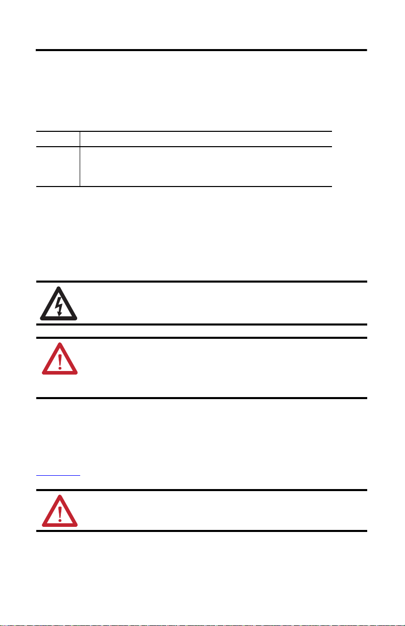
Highest Power Utilization Lowest Power Utilization
Integrated Axis
Module
Axis Modules
Shunt
Module
Slot Filler
Module
IPIM Module
Axis Modules
Determining Mounting Order
Refer to the Module Mounting Order Example diagram below and mount the modules in the
order (left to right) shown. Install modules according to power utilization (highest to lowest)
from left to right starting with the highest power utilization. If power utilization is unknown,
position modules (highest to lowest) from left to right based on the IPIM or AM module
continuous power rating (kW).
Power utilization is the average power (kW) consumed by a servo axis. If the servo axis has been
sized by using Motion Analyzer software, version 6.000 or later, the calculated axis power
required can be used for power utilization. If the servo axis has not been sized in Motion
Analyzer, the following table showing the maximum continuous power for IPIM and AM
modules can be used to determine desired location on a power rail.
Module Type and Continuous Power Output
2094-BM05-S
Axis Module
22.0 kW 15.0 kW 13.5 kW 6.6 kW 3.9 kW 1.8 kW
The IPIM module may be installed on a power rail with an IAM module configured as a
common bus follower, but you will be responsible for configuring the leader for the appropriate
additional capacitance in the follower power rail, including the IPIM module.
Module Mounting Order Example
2094-SEPM-B24-S
IPIM Module
2094-BM03-S
Axis Module
2094-BM02-S
Axis Module
2094-BM01-S
Axis Module
2094-BMP5-S
Axis Module
Publication 2094-IN016A-EN-P - February 2012
Page 6

6 Kinetix 6000M Integrated Drive-Motor Power Interface Module
IMPORTANT
Slots for Additional Modules
Power R ail Slo t
Mounting Bracket
Power R ail
The IAM must be positioned in the leftmost slot of the power rail. Position your other modules
to the right of the IAM module.
Mount modules according to power utilization (highest to lowest) from left to right starting
with the highest power utilization. If power utilization is unknown, position modules (highest
to lowest) from left to right based on continuous power rating (kW). Refer to page 5
The shunt module must be installed to the right of the last module. Install only slot-filler
modules to the right of the shunt module.
Do not mount the shunt module on power rails with a follower IAM module. Common bus
follower IAM modules disable the internal, rail mounted, and external shunt modules.
SHOCK HAZARD: To avoid personal injury due to electrical shock, place a 2094-PRF slot-filler
module in all empty slots on the power rail. Any power rail connector without a module installed
will disable the drive system, however, control power will still be present.
Mount the IPIM Module
All modules mount to the power rail by using the same technique.
1. Remove the protective covers from the power rail connectors.
2. Determine the next available slot and module for mounting.
3. Inspect the module connector pins and power rail connectors and remove any foreign
objects.
.
Publication 2094-IN016A-EN-P - February 2012
ATT EN TI ON : To avoid damage to the pins located on the back of the module and to
make sure that module pins mate properly with the power rail, hang modules as shown.
4. Hang the module mounting bracket from the slot on the power rail.
Page 7

Kinetix 6000M Integrated Drive-Motor Power Interface Module 7
Guide Pin Hole
Rear View Side View
Power R ail
Guide Pin
Pivot module downward
and align with pin.
Power R ail
Bracket Secured in Slot
Flat
2.26 N•m (20 lb•in)
5. Pivot module downward and align the guide pin on the power rail with the guide pin
hole in the back of the module.
Fuse Access
See User Manual Before Removing
6. Gently push the module against the power rail connectors and into the final mounting
position.
7. Tighten the mounting screws.
8. Repeat the above steps for each module being installed.
Publication 2094-IN016A-EN-P - February 2012
Page 8

8 Kinetix 6000M Integrated Drive-Motor Power Interface Module
➋
➊
➌
➏
➍
➎
➒
➑
➐
➓
Feature and Connector Identification
SH1
42+
42-
SH2
CN-
CN+
OUT
RTN
SH3
SE1
SE-
SE2
ETHERNET 1
ETHERNET 2
NETWORK
Item Description Item Description
Hybrid cable DC bus connector
➊
Hybrid cable communication signals connector
➋
Safe-off connector
➌
Enable connector
➍
Sercos RX and TX fiber-optic connectors Fuse holder
➎
LCD display Hybrid cable shield clamp
➏
(1) Refer to th e Kinetix 6000M Integrated Drive-Motor System User Manual, publication 2094-UM003, for details.
➐
➑
➒
➓
ATTENTION: To avoid damage to the sercos RX and TX connectors, use only finger-tight torque
when attaching the fiber-optic cables to the modules. Do not use a wrench or any other
mechanical assistance. For more information, refer to Fiber-optic Cable Installation and Handling
Instructions, publication 2090-IN010
.
Publication 2094-IN016A-EN-P - February 2012
Navigation buttons
Status indicators
EtherNet/IP ports
IDM network cable connector
(1)
(1)
Page 9

Kinetix 6000M Integrated Drive-Motor Power Interface Module 9
PORT 1 PORT 2 NETWORK
2090-CNSSPRS-AAxx or
2090-CNSSPSS-AAxx
2090-CNSSPRS-AAxx
2090-CNSSPSS-AAxx
Wiring
ATTENTION: To avoid personal injury and/or equipment damage, make sure that installation
complie s with specifications regarding wire types, conductor sizes, branch circuit protection, and
disconnect devices. The National Electrical Code (NEC) and local codes outline provisions for safely
installing electrical equipment.
Interconnecting the IPIM Module and IDM Units
A hybrid cable, catalog number 2090-CHBIFS8-12AAxx, transfers DC bus power and
inter-module communication signals from the IPIM module to the first IDM unit. Additional
IDM units are daisy chained by using a 2090-CHBP8S8-12AAxx cable as shown in IPIM and
IDM Interconnect on page 3.
DC+
DC+ (brown)
PE
PE (green)
DC-
DC- (grey)
42-
42- (white/blue)
42+
CN-
CN+
SH2
RTN
OUT
SE1
SE2
SE-
SH3
42+ (blue)
CN- (blue)
CN+ (white)
SH2 (drain)
RTN (pink)
OUT (white/pink)
SE1 (orange)
SE2 (yellow)
SE- (violet)
SH3 (drain)
DC Bus
Power Communication
Control
The IDM system network is routed by using
2090-CNSxPxS-AAxx cables. A 2090-CNSSPRS-AAxx
or 2090-CNSSPSS-AAxx cable is required for connection
to the IPIM module.
When installing network cables, torque the connector plug to 0.8…1.2 N•m (7.1…10.6 lb•in) to
fully seat the contacts and secure the connection.
Publication 2094-IN016A-EN-P - February 2012
Page 10

10 Kinetix 6000M Integrated Drive-Motor Power Interface Module
Wiring the Connectors
You can wire the connectors by using the following guidelines.
Hybrid Cable DC Bus Connector
DC-
1
This connector supplies the DC bus voltage. Three wires from the Hybrid
Power and Communication cable (catalog number 2090-CHBIFS8-12AAxx)
are used to extend this voltage to the first IDM unit.
Terminal Description Signal Strip Length
mm (in.)
1 DC Bus Supply (-) DC- DC- 9.7 (0.38) 0.75 (6.6)
2 PE Ground PE PE
3 DC bus supply (+) DC+ DC+
Hybrid Cable Communication Signals Connector
1
The hybrid communication connector extends control power,
Shield
Tor que
N•m (lb•in)
42+
42-
SH2
CN-
CN+
OUT
RTN
SH3
communication, and safety signals to the first IDM unit. The
2090-CHBIFS8-12AAxx cable interfaces with this connector.
Terminal Description Signal Strip Length
mm (in.)
1 Shield – – 6.4 (0.25) 0.235 (2.0)
2 Control Power +42V DC 42+ 42+
3 Control Power -42V DC 42- 42-
4 CAN Bus Shield IDM CAN SHIELD SH2
5 IDM CAN Bus Lo IDM CAN LO CN-
6 IDM CAN Bus Hi IDM CAN HI CN+
7 System OK out to ID Ms IDM SYSOKOUT OUT
8 System OK return from IDMs IDM SYSOKRTN RTN
9 Safety Shield SAFETY SHIELD SH3
10 Safety Enable Input 1 SAFETY ENABLE 1+ SE1
11 Safety Enable Common SAFETY ENABLE- SE-
12 Safety Enable Input 2 SAFETY ENABLE 2+ SE2
Tor que
N•m (lb•in)
PE
DC+
SE1
SE-
SE2
Publication 2094-IN016A-EN-P - February 2012
Page 11

Kinetix 6000M Integrated Drive-Motor Power Interface Module 11
1
F2+
F2-
F1+
F1-
SE2
SE-
SE1
24+
24-
Motion-allowed Jumper
(not installed)
Wirin g Plug He ader
Safe-off Connector
Each IPIM module ships with the wiring-plug
header and motion-allowed jumper installed in the
Safe-off Connector. With the jumper installed, the
safe-off feature is not used.
This connector extends the safe-off signals for use in
wiring single and multiple safe-off drive
configurations, or to jumper around (not use) the safe-off feature. Refer to the Integrated
Drive-Motor System User Manual, publication 2094-UM003
, for further information.
Terminal Description Signal Strip
Length
mm (in.)
Tor que
N•m (lb•in)
Min/Max
Wire Size
mm2 (AWG)
(1)
1 Feedback Monitoring 2+ FDBK2+ F2+ 7.0 (0.275) 0.235 (2.0) 0.14…1.5
2 Feedback Monitoring 2- FDBK2- F2-
(30…14)
3 Feedback Monitoring 1+ FDBK1+ F1+
4 Feedback Monitoring 1- FDBK1- F1-
5 Safety Enable Input 2 SAFETY ENABLE2+ SE2
6 Safety Enable Common SAFETY ENABLE- SE-
7 Safety Enable Input 1 SAFETY ENABLE1+ SE1
8 Safety Bypass Supply, +24V DC,
24+ 24+
320 mA max
9 Safety Bypass supply, Common 24V COM 24-
(1) Maximum/minimum that the connector will accept—these are not recommendations.
Enable Input
+
EN
1
-
One digital input is supplied to enable all connected IDM units. The enable
status is transmitted to all of the IDM units through the CAN bus.
Terminal Description Signal Strip Length
mm (in.)
1 +24V DC Enable Supply ENABLE 24V+ + 7.0 (0.275) 0.235 (2.0) 0.14…1.5
2 Enable Input ENABLE INPUT EN
Publication 2094-IN016A-EN-P - February 2012
3 24V DC Common ENABLE 24V COM -
(1) Maximum/minimum that the connector will accept—these are not recommendations.
Tor que
N•m (lb•in)
Min/Max
Wire Size
mm2 (AWG)
(30…14)
(1)
Page 12

12 Kinetix 6000M Integrated Drive-Motor Power Interface Module
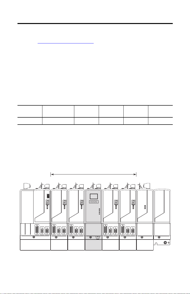
PORT 1 PORT 2 NETWORK
249 (9.8)
256
(10.1)
70 (2.76)
263 (10.3)
Fuse Access
See User Manual Before Removing
287
(11.3)
Power R ail
Power R ail
Dimensions
Publication 2094-IN016A-EN-P - February 2012
Page 13

Kinetix 6000M Integrated Drive-Motor Power Interface Module 13
Additional Resources
These documents contain additional information concerning related products from
Rockwell Automation.
Resource Description
Kinetix 6000M Integrated Drive-Motor User Manual,
publication 2094-UM003
Kinetix 6000 Multi-axis Servo Drive User Manual, publication
2094-UM001
Kinetix 6200 and Kinetix 6500 Multi-axis Ser vo Drive User
Manual, publication 2094-UM002
Kinetix 6000 Power Rail Installation Instructions, publication
2094-IN003
Kinetix 6000 Shunt Module Installation Instructions,
publication 2094-IN004
Line Interface Module Installation Instructions, publication
2094-IN005
2094 Mounting Bracket Installation Instructions, publication
2094-IN008
System Design for Control of Electrical Noise Reference Manual,
publication GMC-RM001
EMC Noise Management DVD, publication GMC-SP001
Kinetix Safe-off Feature Safety Reference Manual, publication
GMC-RM002
Kinetix Rotary Motion Technical Data, publication GMC-TD001
Rockwell Automation Configuration and Selection Tools,
website http://rockwellautomation.com/en/e-tools
Rockwell Automation Product Certification, website
http://rockwellautomation.com/products/certification
National Electrical Code, published by the National Fire
Protection Association of Boston, MA
Rockwell Automation Industrial Automation Glossary,
publication AG-7.1
Information on installing, configuring, startup,
troubleshooting, and applications for your IDM drive system.
Information on installing, configuring, startup,
troubleshooting, and applications for your Kinetix 6000 servo
drive system.
Information on installing, configuring, startup,
troubleshooting, and applications for your Kinetix 6200 or
Kinetix 6500 servo drive system.
Information on the installation of your Bulletin 2094 Power
Rail.
Information on the installation of your Bulletin 2094 Shunt
Module.
Information on the installation and troubleshooting of your
Bulletin 2094 Line Interface Module (LIM).
Information on the installation of Bulletin 2094 Mounting
Brackets.
Information, examples, and techniques designed to minimize
system failures caused by electrical noise.
Information on wiring and troubleshooting your Kinetix 6000
safety drive.
Catalog number information and specifications for
Allen-Bradley rotary motors.
Online product selection and system configuration tools,
including AutoCAD (DXF) drawings.
For declarations of conformity (DoC) currently available from
Rockwell Automation.
An article on wire sizes and types for grounding electrical
equipment.
A glossary of industrial automation terms and abbreviations.
You can view or download publications at http://www.rockwellautomation.com/literature/
. To
order paper copies of technical documentation, contact your local Allen-Bradley distributor or
Rockwell Automation sales representative.
Publication 2094-IN016A-EN-P - February 2012
Page 14

14 Kinetix 6000M Integrated Drive-Motor Power Interface Module
Notes:
Publication 2094-IN016A-EN-P - February 2012
Page 15

Notes:
Kinetix 6000M Integrated Drive-Motor Power Interface Module 15
Publication 2094-IN016A-EN-P - February 2012
Page 16

Rockwell Automation Support
Rockwell Automation provides tec hnical information on the Web to assist you in using its products.
At http://www.rockwellautomation.com/support
links to software service packs, and a MySupport feature that you can customize to make the best use of these tools. You can also visit
our Knowledgebase at http://www.rockwellautomation.com/knowledgebase
forums, software updates, and to sign up for product notification updates.
For an additional level of technical phone support for installation, configuration and troubleshooting, we offer TechConnect
programs. For more information, contact your local distributor or Rockwell Automation representative, or visit
http://www.rockwellautomation.com/support/
Installation Assistance
If you experience a problem within the first 24 hours of installation, please review the information that's contained in this manual.
You can also contact a special Customer Support number for initial help in getting your product up and running.
United States or Canada 1.440.646.3434
Outside United States or
Canada
Use the Wor ldwi de Loc ator
http://www.rockwellautomation.com/support/americas/phone_en.html
Rockwell Automation representative.
New Product Satisfaction Return
Rockwell Automation tests all o f its products to ensure that they are fully operational when shipped from the manufacturing facility.
However, if your product is not functioning and needs to be returned, follow these procedures.
, you can find technical manuals, technical and application notes, sample code and
for FAQs, technical information, support chat and
sm
support
.
at
, or contact your local
United States
Outside United States Please contact your local Rockwell Automation representative for the return procedure.
Contact your distributor. You must provide a Customer Support case number (call the phone number
above to obtain one) to your distributor to complete the return process.
Documentation Feedback
Your comments will help us serve your documentation needs better. If you have any suggestions on how to improve this document,
complete this form, publication RA-DU002
Allen-Bradley, Rockwell Software, Rockwell Automation, CompactLogix, ControlLogix, Kinetix, SoftLogix, RSLogix, and TechConnect are
trademarks of Rockwe ll Automation, Inc.
Trademarks not belonging to Rockwell Automation are property of their respective companies.
Rockwell Otomasyon Ticaret A.Ş., Kar Plaza İş Merkezi E Blok Kat:6 34752 İçerenköy, İstanbul, Tel: +90 (216) 5698400
Publication 2094-IN016A-EN-P - February 2012 PN-138110
Copyright © 2012 Rockwell Automation, Inc. All rights reserved. Printed in the U.S.A.
, available at http://www.rockwellautomation.com/literature/.
 Loading...