

Page 1
Installation Instructions
Kinetix 6000 Power Rail
Catalog Numbers 2094-PRS1, 2094-PRS2, 2094-PRS3,
2094-PRS4, 2094-PRS5, 2094-PRS6, 2094-PRS7, 2094-PRS8,
2094-PR1, 2094-PR2, 2094-PR4, 2094-PR6, 2094-PR8
Top ic Pa ge
About the Kinetix 6000 Power Rail 1
Important User Information 2
Catalog Number Explanation 3
Before You Begin 3
Install the Kinetix 6000 Power Rail 4
Product Dimensions 6
Additional Resources 8
About the Kinetix 6000 Power Rail
The Kinetix 6000 power rail provides power and control signals from the Bulletin 2094
integrated axis (IAM) converter module to adjacent axis (AM) inverter, shunt, and slot-filler
modules. The Bulletin 2094 IAM and AM modules, and Kinetix 6000 shunt and slot-filler
modules mount on the Kinetix 6000 power rail.
For detailed information on wiring, applying power, troubleshooting, and integration
with ControlLogix, CompactLogix, and SoftLogix controller platforms, refer to
Additional Resources
Refer to the System Design for Control of Electrical Noise Reference Manual, publication
GMC-RM001
on page 8, for the appropriate Bulletin 2094 servo drive user manual.
, for greater detail on reducing electrical noise when installing your power rail.
Page 2
2 Kinetix 6000 Power Rail
IMPORTANT
Important User Information
Solid state equipment has operational characteristics differing from those of electromechanical equipment.
Safety Guidelines for the Application, Installation and Maintenance of Solid State Controls (publication
SGI-1.1
available from your local Rockwell Automation sales office or online at
http://www.rockwellautomation.com/literature
equipment and hard-wired electromechanical devices. Because of this difference, and also because of the
wide variety of uses for solid state equipment, all persons responsible for applying this equipment must
satisfy themselves that each intended application of this equipment is acceptable.
In no event will Rockwell Automation, Inc. be responsible or liable for indirect or consequential damages
resulting from the use or application of this equipment.
The examples and diagrams in this manual are included solely for illustrative purposes. Because of the many
variables and requirements associated with any particular installation, Rockwell Automation, Inc. cannot
assume responsibility or liability for actual use based on the examples and diagrams.
No patent liability is assumed by Rockwell Automation, Inc. with respect to use of information, circuits,
equipment, or software described in this manual.
Reproduction of the contents of this manual, in whole or in part, without written permission of Rockwell
Automation, Inc., is prohibited.
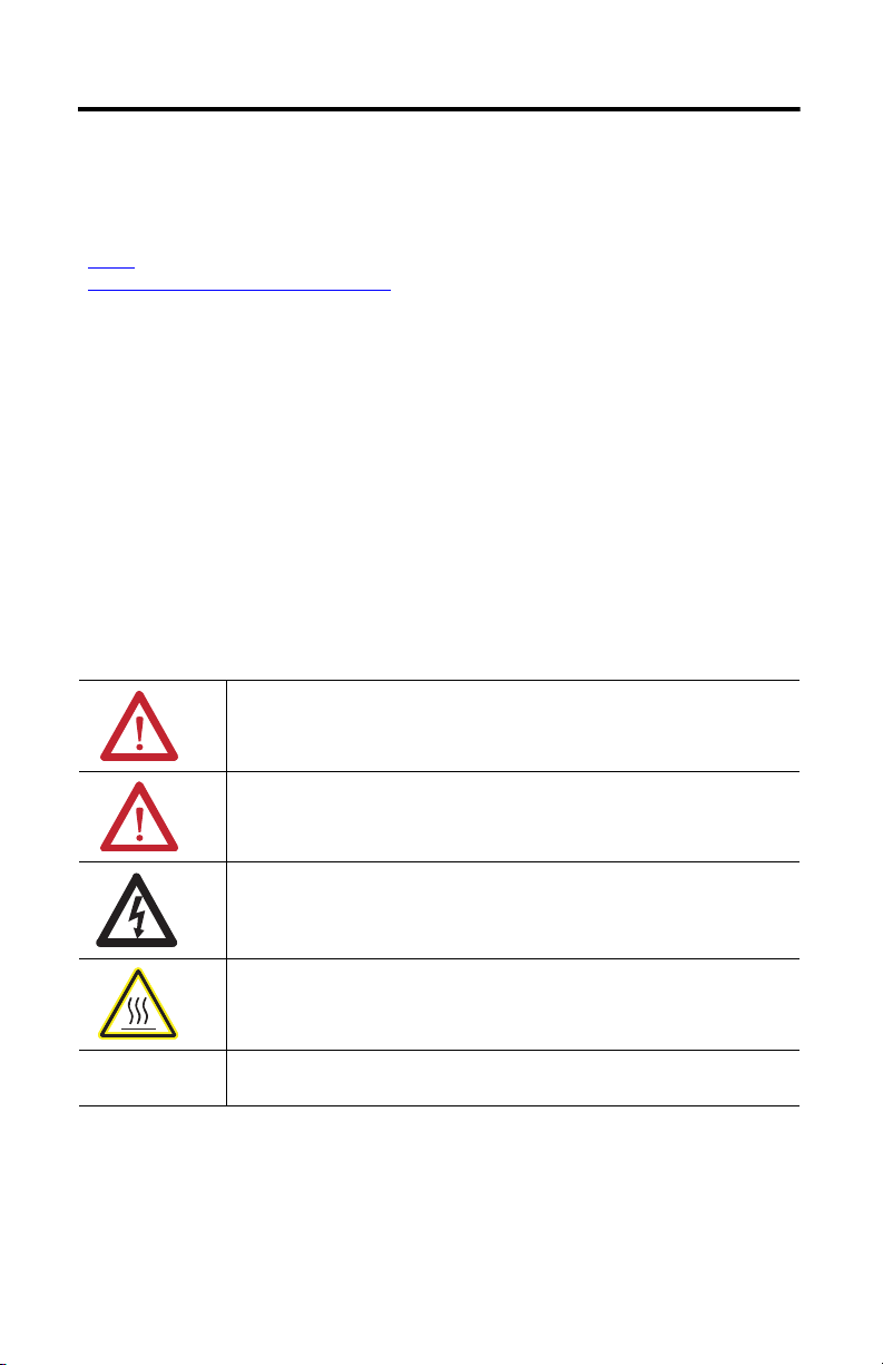
Throughout this manual, when necessary, we use notes to make you aware of safety considerations.
WARNING: Identifies information about practices or circumstances that can cause an
explosion in a hazardous environment, which may lead to personal injury or death,
property damage, or economic loss.
) describes some important differences between solid state
Publication 2094-IN003D-EN-P - November 2010
ATTENTION: Identifies information about practices or circumstances that can lead to
personal injury or death, property damage, or economic loss. Attentions help you
identify a hazard, avoid a hazard and recognize the consequences.
SHOCK HAZARD: Labels may be on or inside the equipment (for example, drive or
motor) to alert people that dangerous voltage may be present.
BURN HAZARD: Labels may be on or inside the equipment (for example, drive or
motor) to alert people that surfaces may reach dangerous temperatures.
Identifies information that is critical for successful application and understanding of
the product.
Page 3
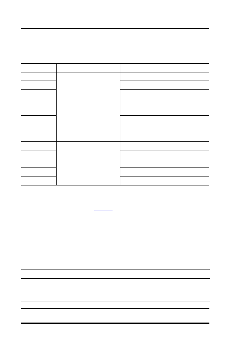
Catalog Number Explanation
IMPORTANT
This publication applies to the following Bulletin 2094 power rails.
Kinetix 6000 Power Rail 3
Cat. No. Description Module Capacity
2094-PRS1
2094-PRS2 1 IAM module and up to 1 additional module
2094-PRS3 1 IAM module and up to 2 additional modules
2094-PRS4 1 IAM module and up to 3 additional modules
2094-PRS5 1 IAM module and up to 4 additional modules
2094-PRS6 1 IAM module and up to 5 additional modules
2094-PRS7 1 IAM module and up to 6 additional modules
2094-PRS8 1 IAM module and up to 7 additional modules
2094-PR1
2094-PR2 1 IAM module and up to 1 additional module
2094-PR4 1 IAM module and up to 3 additional modules
2094-PR6 1 IAM module and up to 5 additional modules
2094-PR8 1 IAM module and up to 7 additional modules
(1) Module capacity is reduced when using double-wide IAM and AM modules. The 2094-AC32-M05-x, 2094-BC04-M03-x, and
2094-BC07-M05-x double-wide IAM modules each require one converter slot and two inverter slots. All other (single-wide)
IAM modules require one converter slot and one inverter slot. The 2094-BM03-x and 2094-BM05-x double-wide AM
modules each require two inverter slots. All other (single-wide) AM modules require one inverter slot. Refer to the Kinetix
Motion Control Selection Guide, publication GMC-SG001
Power rail (slim),
230V or 460V drive systems
Power rail,
230V or 460V drive systems
1 IAM module and no additional modules
1 IAM module and no additional modules
, for more information on selecting Bulletin 2094 power rails.
(1)
Before You Begin
Remove all packing material, wedges, and braces from within and around the components. After
unpacking, check the item nameplate catalog number against the purchase order.
Parts List
Drive Component Ships With
Power Rail
• One braided 100 mm (3.9 in.) ground strap
• Protective covers (one covering each of the power rail connectors)
• These installation instructions, publication 2094-IN003
To improve the bond between the power rail and subpanel, construct your
subpanel out of zinc plated (paint free) steel.
Publication 2094-IN003D-EN-P - November 2010
Page 4

4 Kinetix 6000 Power Rail
Install the Kinetix 6000 Power Rail
This procedure assumes that you have prepared your panel and understand how to bond your
system. For installation instructions regarding equipment and accessories not included here, refer
to the instructions that came with those products.
SHOCK HAZARD: To avoid hazard of electrical shock, perform all mounting and
wiring of the Bulletin 2094 power rail and drive modules prior to applying power.
Once power is applied, connector terminals may have voltage present even when
not in use.
ATTENTION: Plan the installation of your system so that you can perform all
cutting, drilling, tapping, and welding with the system removed from the enclosure.
Because the system is of open type construction, be careful to keep any metal
debris from falling into it. Metal debris or other foreign matter can become lodged
in the circuitry, which can result in damage to components.
Using Bulletin 2094 Mounting Brackets
Bulletin 2094 mounting brackets can be used to mount the power rail over the AC line filter.
Refer to the 2094 Mounting Brackets Installation Instructions, publication 2094-IN008, when
using mounting brackets with your Kinetix 6000 drive system.
Mount the Kinetix 6000 Power Rail
The Kinetix 6000 power rail comes in lengths to support one IAM module, and up to seven
additional AM modules or up to six additional AM modules and one shunt module. The
connector pins for each slot are covered by a protective cover. The cover is designed to protect
the pins from damage and make sure that no foreign objects lodge between the pins during
installation.
ATTENTION: To avoid damage to power-rail connector pins during installation, do
not remove the protective covers until the module for each slot is ready for
mounting.
Publication 2094-IN003D-EN-P - November 2010
Page 5

Kinetix 6000 Power Rail 5
IMPORTANT
LIM
PRS
PR
Bonded Cabinet Ground Bus
2094-PRSx or 2094-PRx Power Rail
(2094-PRS8 power rail is shown)
2094-PRSx or 2094-PRx Power Rail
on Bulletin 2094 Mounting Brackets
(2094-PRSx power rail is shown)
Ground Grid or Power
Distribution Ground
Braided Ground Strap, 100 mm (3.9 in.)
Braided Ground Strap, 100 mm (3.9 in.)
Ground Stud
Ground Stud
2094-XNBRKT-1 Mounting Bracket
Bonded Cabinet Ground Bus
Ground Grid or Power
Distribution Ground
Follow these steps to mount your 2094-PRSx or 2094-PRx power rail.
1. Lay out the position for your power rail in the enclosure.
Refer to your servo drive user manual for panel layout recommendations. Mounting hole
dimensions for the power rail are shown in the figures on page 6.
2. Attach the power rail to the cabinet.
The recommended mounting hardware is M6 metric (1/4x20) bolts. Refer to the System
Design for Control of Electrical Noise Reference Manual, publication GMC-RM001
for HF bonding techniques.
To improve the bond between the power rail and subpanel, construct
your subpanel out of zinc plated (paint-free) steel.
3. Tighten all mounting fasteners.
Apply 5.08 N•m (45.0 lb•in) torque.
4. Attach the braided grounding strap from the grounding stud to the bonded cabinet
ground.
,
Publication 2094-IN003D-EN-P - November 2010
Page 6

6 Kinetix 6000 Power Rail
Dimensions are in mm (in.)
Dimensions are in mm (in.)
Product Dimensions
These are the mounting dimensions for the Bulletin 2094 power rail.
2094-PRS1 (Slim) Power Rail
134.6
69.9
(2.75)
88.9
(3.5)
(5.3)
Ø 7.95
(O.313) TYP.
12.4
(0.50)
25.4
(1.0)
22.9
(0.90)
35.1
231
(1.4)
(9.1)
190.5
(7.5)
2094-PRS2, 2094-PRS3, 2094-PRS4, 2094-PRS5, 2094-PRS6, 2094-PRS7, and
2094-PRS8 (Slim) Power Rails
22.9
231
(9.1)
190.5
(7.5)
(0.90)
35.1
(1.4)
Ø 7.95
(O.313) TYP.
C
Cat. No. Description Dimension A
2094-PRS2 2-axis power rail 205.7 (8.10) 124.5 (4.90) N/A
A
B
mm (in.)
Dimension B
mm (in.)
Dimension C
mm (in.)
2094-PRS3 3-axis power rail 276.9 (10.90) 195.6 (7.70) N/A
2094-PRS4 4-axis power rail 348.0 (13.70) 266.7 (10.50) N/A
2094-PRS5 5-axis power rail 419.1 (16.50) 337.8 (13.30) 195.6 (7.70)
2094-PRS6 6-axis power rail 490.2 (19.30) 408.9 (16.10) 195.6 (7.70)
2094-PRS7 7-axis power rail 561.3 (22.10) 480.1 (18.90) 266.7 (10.50)
2094-PRS8 8-axis power rail 632.5 (24.90) 551.2 (21.70) 266.7 (10.50)
Publication 2094-IN003D-EN-P - November 2010
12.4
(0.50)
25.4
(1.0)
Page 7

Kinetix 6000 Power Rail 7
25.4
(1.0)
12.7
(0.50)
198.1
(7.80)
A
B
C
12.2
(0.48)
Ø 15.88
(O.625) TYP.
Ø 7.95
(O.313) TYP.
25.4
(1.0)
146.05
(5.75)
Dimensions are in mm (in.)
2094-PR1, 2094-PR2, 2094-PR4, 2094-PR6, and 2094-PR8 Power Rails
Cat. No. Description Dimension A
mm (in.)
Dimension B
mm (in.)
2094-PR1 1-axis power rail 185.42 (7.30) 160.02 (6.30) N/A
2094-PR2 2-axis power rail 256.54 (10.10) 231.14 (9.10) N/A
2094-PR4 4-axis power rail 398.78 (15.70) 373.38 (14.70) N/A
2094-PR6 6-axis power rail 541.02 (21.30) 515.62 (20.30) 302.26 (11.90)
2094-PR8 8-axis power rail 683.26 (26.90) 657.86 (25.90) 373.38 (14.70)
Publication 2094-IN003D-EN-P - November 2010
Dimension C
mm (in.)
Page 8

Additional Resources
These documents contain additional information concerning related Rockwell Automation
products.
Resource Description
Kinetix 6000 Multi-axis Servo Drive User Manual,
publication 2094-UM001
Kinetix 6200 and Kinetix 6500 Multi-axis Servo Drive User
Manual, publication 2094-UM002
Kinetix 6000 Shunt Module Installation Instructions,
publication 2094-IN004
Kinetix 6000 Slot-filler Module Installation Instructions,
publication 2094-IN006
2094 Mounting Bracket Installation Instructions,
publication 2094-IN008
System Design for Control of Electrical Noise Reference
Manual, publication GMC-RM001
EMC Noise Management DVD, publication GMC-SP001
Kinetix Motion Control Selection Guide,
publication GMC-SG001
Rockwell Automation Configuration and Selection Tools,
website http://www.ab.com/e-tools
Rockwell Automation Product Certification, website
http://www.rockwellautomation.com/products/certification
National Electrical Code, published by the National Fire
Protection Association of Boston, MA
Rockwell Automation Industrial Automation Glossary,
publication AG-7.1
Information on installing, configuring, startup,
troubleshooting, and wiring diagrams for your
Bulletin 2094 servo drive system.
Information on the installation of your Bulletin
2094 shunt module.
Information on the installation of your Bulletin
2094 slot-filler module.
Information on the installation of Bulletin 2094
mounting brackets.
Information, examples, and techniques
designed to minimize system failures caused
by electrical noise.
Specifications, motor/servo-drive system
combinations, and accessories for Kinetix
Motion Control products.
Online product selection and system
configuration tools, including AutoCAD (DXF)
drawings.
For declarations of conformity (DoC) currently
available from Rockwell Automation.
An article on wire sizes and types for
grounding electrical equipment.
A glossary of industrial automation terms and
abbreviations.
You can view or download publications at http://www.rockwellautomation.com/literature. To
order paper copies of technical documentation, contact your local Rockwell Automation
distributor or sales representative.
Allen-Bradley, CompactLogix, ControlLogix, Kinetix, Rockwell Software, Rockwell Automation, Rockwell Software, and SoftLogix are
trademarks of Rockwell Automation, Inc.
Trademarks not belonging to Rockwell Automation are property of their respective companies.
Rockwell Otomasyon Ticaret A.Ş., Kar Plaza İş Merkezi E Blok Kat:6 34752 İçerenköy, İstanbul, Tel: +90 (216) 5698400
Publication 2094-IN003D-EN-P - November 2010 PN-93743
Supersedes Publication 2094-IN003C-EN-P - June 2008 Copyright © 2010 Rockwell Automation, Inc. All rights reserved. Printed in the U.S.A.
 Loading...