

Page 1
Installation Instructions
Low-profile Connector Kit for I/O, Safety,
and Auxiliary Feedback Signals
Catalog Number 2090-K6CK-D44M
About the Low-profile Connector Kit
This low-profile 44-pin connector kit provides termination points for I/O, safety, and auxiliary
feedback connections on the IOD connector of Kinetix® 6200 and Kinetix 6500 drives.
This kit also includes a motion-allowed jumper that you install when the safe torque-off
functionality of 2094-xx02x-M0x-S0 control modules is not desired. The jumper does not apply
to 2094-xx02x-M0x-S1 control modules.
These documents contain additional information for wiring the I/O, safety, and auxiliary
feedback connections on Kinetix 6200 and Kinetix 6500 servo drives.
Resource Description
Kinetix 6200 and Kinetix 6500 Modular Multi-axis Ser vo Drive
User Manual, publication 2094-UM002
Kinetix 6200 and Kinetix 6500 Safe Speed Monitoring Servo
Drives Safety Reference Manual, publication 2094-RM001
Kinetix 6200 and Kinetix 6500 Safe Torque-off Servo Drives
Safety Reference Manual, publication 2094-RM002
Provides information on wiring digital inputs, registration
inputs, and auxiliary feedback (IOD) connections.
Provides information on wiring the safety (IOD) connections on
2094-xx02x-M0x-S1 control modules.
Provides information on wiring the safety (IOD) connections on
2094-xx02x-M0x-S0 control modules.
Page 2
2 Low-profile Connector Kit for I/O, Safety, and Auxiliary Feedback Signals
28 27 26 25 24 23 22 21 20 19 18 17 15 14 0
AUX FEEDBACK
0 11 10 9 8 7 6 5 4 3 2 1
0 39 41 40 39 42 40 39 43 40 39 44 40
INPUTS
0 38 37 36 35 34 33 32 31 30 29 28 27 28 27 28 27 28 27
S1 ONLY
S1 ONLY
S0&S1 W/S0 DISABLED
28 27 26 25 24 23 22 21 20 19 18 17 15 14 0
AUX FEEDBACK
0 11 10 9 8 7 6 5 4 3 2 1
0 39 41 40 39 42 40 39 43 40 39 44 40
INPUTS
0 38 37 36 35 34 33 32 31 30 29
28 27 28 27 28 27 28 27
S1 ONLY
S1 ONLY
S0&S1 W/S0 DISABLED
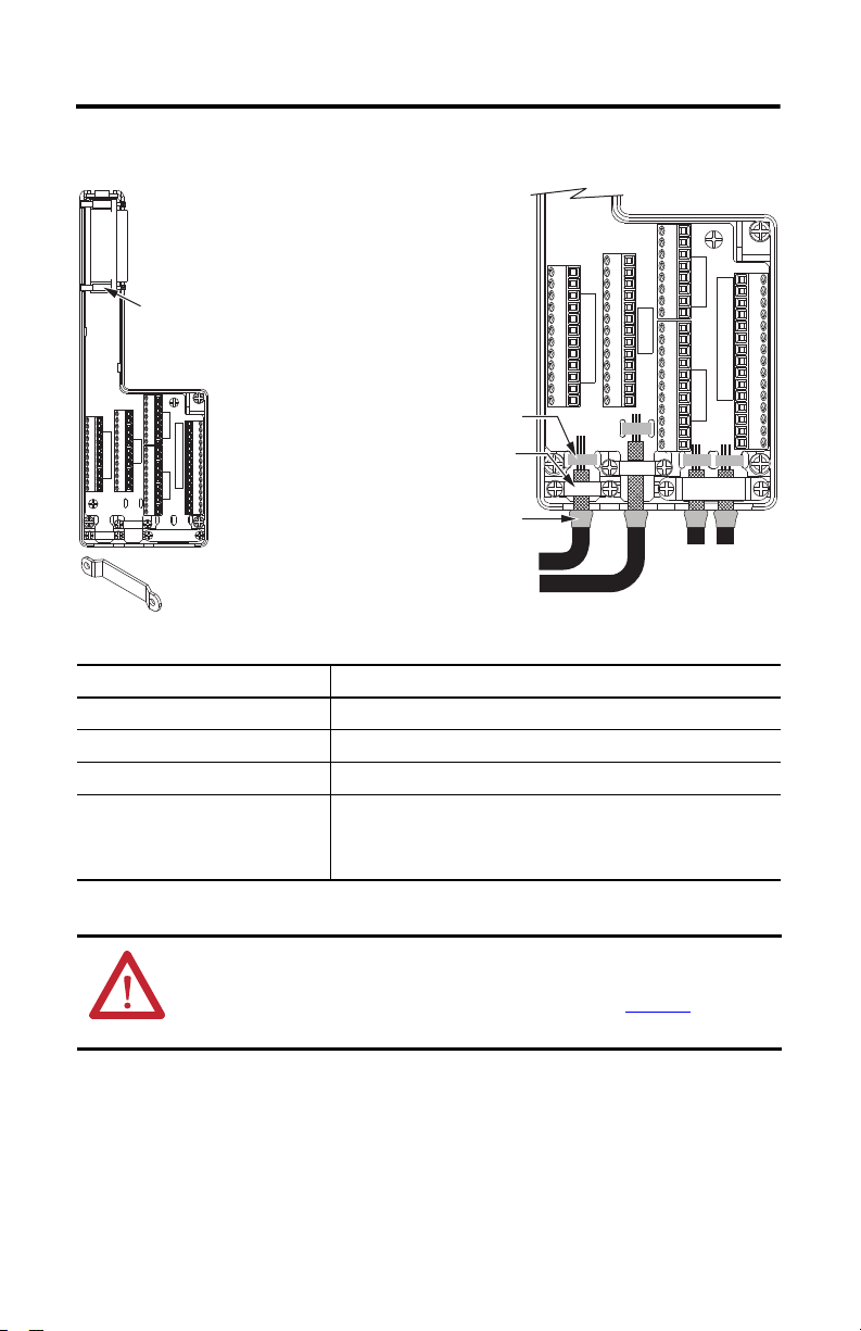
Follow these steps to form a compact connection.
1. Push the insulation down-and-over itself.
2. Move the insulation so it butts against the
outside wall of cover.
3. Tape or shrink-wrap the end of the insulation
to the cable.
Mounting
Screw (2)
If necessary, turn clamp over to hold
small wires secure.
Shrink-wrapped Insulation
Use shield clamps (3) to maximize contact with
cable shield for high-frequency bonding.
Use tie wraps (4) for stress relief.
Aux. Feedback and
I/O Wires and Cables
Safety Wires
and Cables
Install the Low-profile Connector Kit
Attribute 2090-K6CK-D44M
Cable diameter 4…10 mm (0.16…0.39 in.)
2
Screw terminal wire size 0.06…1.31 mm
Recommended wire strip length 5 mm (0.2 in.) single conductor
Recommended torque
Mounting screw
Ter mi nal scr ew s
Clamp and cover screws
0.4 N•m (3.5 lb•in)
0.2 N•m (2.1 lb•in)
0.4 N•m (3.5 lb•in)
(30…16 AWG)
ATTENTION: This connector kit contains electrostatic discharge (ESD) sensitive parts that can be
damaged if you do not follow ESD control procedures. If you are unfamiliar with ESD control
procedures, refer to Guarding Against Electrostatic Damage, publication 8000-4.5.2
Rockwell Automation Publication 2090-IN021C-EN-P - July 2013
applicable ESD protection handbook.
, or any other
Page 3

Connector Data
Motion-allowed Jumper Installation
(applies to 2094-xx02x-M0x-S0
control modules)
Kit pin numbering corresponds to the
IOD connector. Pins 27, 28, 39, and 40
are given multiple terminals to
accommodate additional connections.
AUX FEEDBACK
0 11 10 9 8 7 6 5 4 3 2 1
0 39 41 40 39 42 40 39 43 40 39 44 40
S0&S1 W/S0 DISABLED
S1 ONLY
28 27 28 27 28 27 28 27
INPUTS
S1 ONLY
0 38 37 36 35 34 33 32 31 30 29
Low-profile Connector Kit for I/O, Safety, and Auxiliary Feedback Signals 3
28 27 26 25 24 23 22 21 20 19 18 17 15 14 0
28 27 26 25 24 23 22 21 20 19 18 17 15 14 0
IOD Pin
(1)
Signal IOD Pin
(1)
Signal
0Shield 9EPWR_5V
1
2
3
4
5
6
7 AUX_CLK+ 22 (44) SS_OUT_CH1
8 AUX_CLK– 23 (S52) SLS_IN_CH0
(1) Designators in parentheses refe r to the Guardmaster® MSR57P safety relay and PowerFlex® 750-S eries safety option terminals.
(2) Use this supply to power the Safety 24V (SPWR/SCOM) input. Do not connect this 24V to any external safety device. These pins do not apply to
2094-xx02x-M0x-S1 control modules.
AUX_SIN + 10 ECOM
AUX_A+ 11 EPWR_9V
AUX_SIN – 12 –
AUX_A– 13 –
AUX_COS+ 14 24VPWR
AUX_B+ 15 24VCOM
(2)
(2)
AUX_COS– 16 –
AUX_B– 17 (A1) SPWR
AUX_DATA+ 18 (A2) SCOM
AUX_I+ 19 (S12) SS_IN_CH0
AUX_DATA+ 20 (S22) SS_IN_CH1
AUX_I+ 21 (34) SS_OUT_CH0
Rockwell Automation Publication 2090-IN021C-EN-P - July 2013
Page 4

Connector Data
Motion-allowed Jumper Installation
(applies to 2094-xx02x-M0x-S0
control modules)
Kit pin numbering corresponds to the
IOD connector. Pins 27, 28, 39, and 40
are given multiple terminals to
accommodate additional connections.
AUX FEEDBACK
0 11 10 9 8 7 6 5 4 3 2 1
0 39 41 40 39 42 40 39 43 40 39 44 40
(continued)
S0&S1 W/S0 DISABLED
S1 ONLY
28 27 28 27 28 27 28 27
INPUTS
S1 ONLY
0 38 37 36 35 34 33 32 31 30 29
28 27 26 25 24 23 22 21 20 19 18 17 15 14 0
28 27 26 25 24 23 22 21 20 19 18 17 15 14 0
IOD Pin
(1)
Signal IOD Pin
(1)
Signal
24 (S62) SLS_IN_CH1 35 (51) DC_OUT_CH0
25 RESET_REF 36 (52) DC_OUT_CH1
26 (S34) RESET_IN 37 (S72) ESM_IN_CH0
27 (S11) TEST_OUT_0 38 (S82) ESM_IN_CH1
28 (S21) TEST_OUT_1 39 24VPWR
29 (68) SLS_OUT_CH0 40 24VCOM
(2)
(2)
30 (78) SLS_OUT_CH1 41 INPUT 1
31 (S32) DM_IN_CH0 42 INPUT 2
32 (S42) DM_IN_CH1 43 INPUT 3
33 (X32) LM_IN_CH0 44 INPUT 4
34 (X42) LM_IN_CH1
(1) Designators in parentheses refer to the Guardmaster MSR57P safety relay and PowerFlex 750-Series safety option terminals.
(2) Use these signals as a 24V DC source to ope rate the digital inputs (50 mA maximum per input).
Allen-Bradley, Guardmaster, Kinetix, PowerFlex, Rockwell Software, and Rockwell Automation are trademarks of Rockwell Automation, Inc.
Trademarks not belonging to Rockwell Automation are property of their respective companies.
Rockwell Otomasyon Ticaret A.Ş., Kar Plaza İş Merkezi E Blok Kat:6 34752 İçerenköy, İstanbul, Tel: +90 (216) 5698400
Publication 2090-IN021C-EN-P - July 2013 PN-213380
Supersedes Publication 2090-IN021B-EN-P - August 2010 Copyright © 2013 Rockwell Automation, Inc. All rights reserved. Printed in the U.S.A.
 Loading...