

Page 1
Installation Instructions
WARNING
IMPORTANT
ATTENTION
ATTENTION
ATTENTION
WARNING
ATTENTION
WARNING
WARNING
AVERTISSEMENT
FLEX I/O AC Digital Output Modules
Cat. No. 1794-OA8, 1794-OA8K, 1794-OA8I, 1794-OA16
(Modules with catalog numbers that end in K are conformally coated to meet
noxious gas requirements of ISA/ANSI-71.040-1985 Class G3 Environment.)
Important User Information
Solid state equipment has operational characteristics diff ering from those of electromechanical equipment.
Safety Guidelines for the Application, Installation and Maintenan ce of Solid State Controls (Publication
SGI-1.1 available from your local Rockwell Automation sales office or online at
http://www.literature.rockwellautomation.com) describes some important differen ces between solid state
equipment and hard-wired electromechanica l devices. Because of this difference, and also because of the
wide variety of uses for solid state equipme nt, all persons responsible for applying this equipment must
satisfy themselves that each intended application of t his equipment is acceptable.
In no event will Rockwell Automation , Inc. be responsible or liable for indirect or consequential damages
resulting from the use or application of this equipment.
The examples and diagrams in this manual are included solely for illustrative purposes. Because of the many
variables and requirements associated with a ny particular installation, Rockwell Automation, Inc. cannot
assume responsibility or liability for actual use based o n the examples and diagrams.
No patent liability is assumed by Rockwell Automation, Inc. with respect to use of informat ion, circuits,
equipment, or software described in this manua l.
Reproduction of the contents of this manual , in whole or in part, without written permission of Rockwell
Automation, Inc. is prohibited.
Throughout this manual we use notes to make you awar e of safety considerations.
Identifies information about practices or circumstances t hat can cause an explosion in
a hazardous environment, which m ay lead to personal injury or death, property
damage, or economic loss.
Identifies information that is critical for successful application and understanding of
the product.
Identifies information about practices or circumstances that can lead to personal
injury or death, property damage, or eco nomic loss. Attentions help you identify a
hazard, avoid a hazard, or recognize the con sequence
Environment and Enclosure
This equipment is intended for use in a Pollution Degree 2 industrial environment, in
overvoltage Category II applications (as d efined in IEC 60664-1), at altitudes up to 2000
m (6562 ft) without derating.
This equipment is considered Group 1, Class A ind ustrial equipment according to
IEC/CISPR 11. Without appropriate precaution s, there may be difficulties with
electromagnetic compatibility in residential and other environments due to co nducted
and radiated disturbances.
This equipment is supplied as open-ty pe equipment. It must be mounted within an
enclosure that is suitably designed for those specific environmental conditions that
will be present and appropriately de signed to prevent personal injury resulting from
accessibility to live parts. The enclosure must have suitab le flame-retardant properties
to prevent or minimize the spread of flame, complying with a flame spread rating of
5VA, V2, V1, V0 (or equivalent) if non-metallic. The interior of the enclosure must be
accessible only by the use of a tool. Subsequ ent sections of this publication may
contain additional information reg arding specific enclosure type ratings that are
required to comply with certain product safety certifications.
In addition to this publication, see:
• Industrial Automation Wiring and Gro unding Guidelines, publication 1770-4.1,
for additional installation requirement s
• NEMA Standard 250 and IEC 60529, as appli cable, for explanations of the
degrees of protection provided by en closures
Do not remove or replace a term inal base unit while power is applied. Interruption of
the backplane can result in uninten tional operation or machine motion.
This product is grounded through the DIN rail to chassis ground. Use zinc plated
yellow-chromate steel DIN rail to assure proper grounding. The use of other DIN rail
materials (for example, aluminum or pla stic) that can corrode, oxidize, or are poor
conductors, can result in improper or i ntermittent grounding. Secure DIN rail to
mounting surface approximately every 200 mm (7.8 in.) a nd use end-anchors
appropriately.
For Class I Division 2 applications, use only Class I Division 2 listed or recog nized
accessories and modules approved for used within the 1794 platform.
North American Hazardous Location Approval
The following output modules are North American Hazardous Location approved:
1794-OA8, 1794-OA8K, 1794-OA8I and 1794-OA16.
The following information applies when operating this
equipment in hazardou s locations:
Products marked “CL I, DIV 2, GP A, B, C, D” are suitable for use in
Class I Division 2 Groups A, B, C, D, Hazardous Locations and
nonhazardous locations only. Each product is supplied with
markings on the rating nameplate indicating the hazardous location
temperature code. When combining products within a system, the
most adverse temperature code (lowest “T” number) may be used
to help determine the overall temperature code of the system.
Combinations of equipment in your system are subject to
investigation by the local Authority Having Jurisdiction at the time
of installation.
EXPLOSION HAZARD
• Do not disconnect equipment unless
power has been removed or the area
is known to be nonhazardous.
• Do not disconnect connections to
this equipment unless power has
been removed or the area is known
to be nonhazardous. Secure any
external connections that mate to
this equipment by using screws,
sliding latches, threaded connectors,
or other means provided with this
product.
• Substitution of components may
impair suitability for Class I, Division
2.
• If this product contains batteries,
they must only be changed in an area
known to be nonhazardous.
Informations sur l’utilisation de cet équipement en
environnements dangereux :
Les produits marqués "CL I, DIV 2, GP A, B, C, D" ne
conviennent qu’à une utilisation en environnements de
Classe I Division 2 Groupes A, B, C, D dangereux et non
dangereux. Chaque produit est livré avec des marquages
sur sa plaque d’identification qui indiquent le code de
température pour les environnements dangereux. Lorsque
plusieurs produits sont combinés dans un système, le code
de température le plus défavorable (code de température le
plus faible) peut être utilisé pour déterminer le code de
température global du système. Les combinaisons
d’équipements dans le système sont sujettes à inspection
par les autorités locales qualifiées au moment de
l’installation.
RISQUE D’EXPLOSION
• Couper le courant ou s’assurer
que l’environnement est classé
non dangereux avant de
débrancher l'équipement.
• Couper le courant ou s'assurer
que l’environnement est classé
non dangereux avant de
débrancher les connecteurs.
Fixer tous les connecteurs
externes reliés à cet
équipement à l'aide de vis,
loquets coulissants,
connecteurs filetés ou autres
moyens fournis avec ce produit.
• La substitution de composants
peut rendre cet équipement
inadapté à une utilisation en
environnement de Classe I,
Division 2.
• S’assurer que l’environnement
est classé non dangereux avant
de changer les piles.
European Hazardous Location Approval
The following module is European Zone 2 approved: 1794-OA8K.
The following applies when the product bears the Ex Marking:
This equipment is intended for use in pot entially explosive atmospheres as defined by European Union
Directive 94/9/EC and has been found to comply with the Essential Health and Safety Requirements relating
to the design and construction of Cat egory 3 equipment intended for use in Zone 2 potentially explosive
atmospheres, given in Annex II to this Directive.
Compliance with the Essential Health and Saf ety Requirements has been assured by compliance with EN
60079-15 and EN 60079-0.
If you connect or disconnect wiring while the f ield side power is on, an electrical arc
can occur. This could cause an explosion in hazardous location installat ions. Be sure
that power is removed or the area is n onhazardous before proceeding.
Publication 1794-IN103B-EN-P - May 2011
Page 2
2
WARNING
ATTENTION
WARNING
WARNING
2
3
4
5
6
7
1
45284
IMPORTANT
ATTENTION
Observe the following additional Zone 2 certification
requirements.
• This equipment is not resistant to sunlight o r other sources of UV
radiation.
• This equipment must be installed in an enclosure providing at least
IP54 protection when applied in Zone 2 e nvironments.
• This equipment shall be used within its specified rat ings defined by
Rockwell Automation.
• Provision shall be made to prevent the rated voltage from being
exceeded by transient disturbances of more th an 40% when
applied in Zone 2 environments.
• This equipment must be used only wi th ATEX certified
Rockwell Automation terminal bases.
• Secure any external connections that mate to this equipment by
using screws, sliding latches, threaded connecto rs, or other means
provided with this product.
• Do not disconnect equipment unless power h as been removed or
the area is known to be nonhazardous.
Prevent Electrostatic Discharge
This equipment is sensitive to electrostatic disch arge, which can cause
internal damage and affect normal o peration. Follow these guidelines
when you handle this equipment:
• Touch a grounded object to discharge potential static.
• Wear an approved grounding wriststrap.
• Do not touch connectors or pins on compon ent boards.
• Do not touch circuit components inside the e quipment.
• Use a static-safe workstation, if available.
• Store the equipment in appropriate static-safe packaging when not
in use.
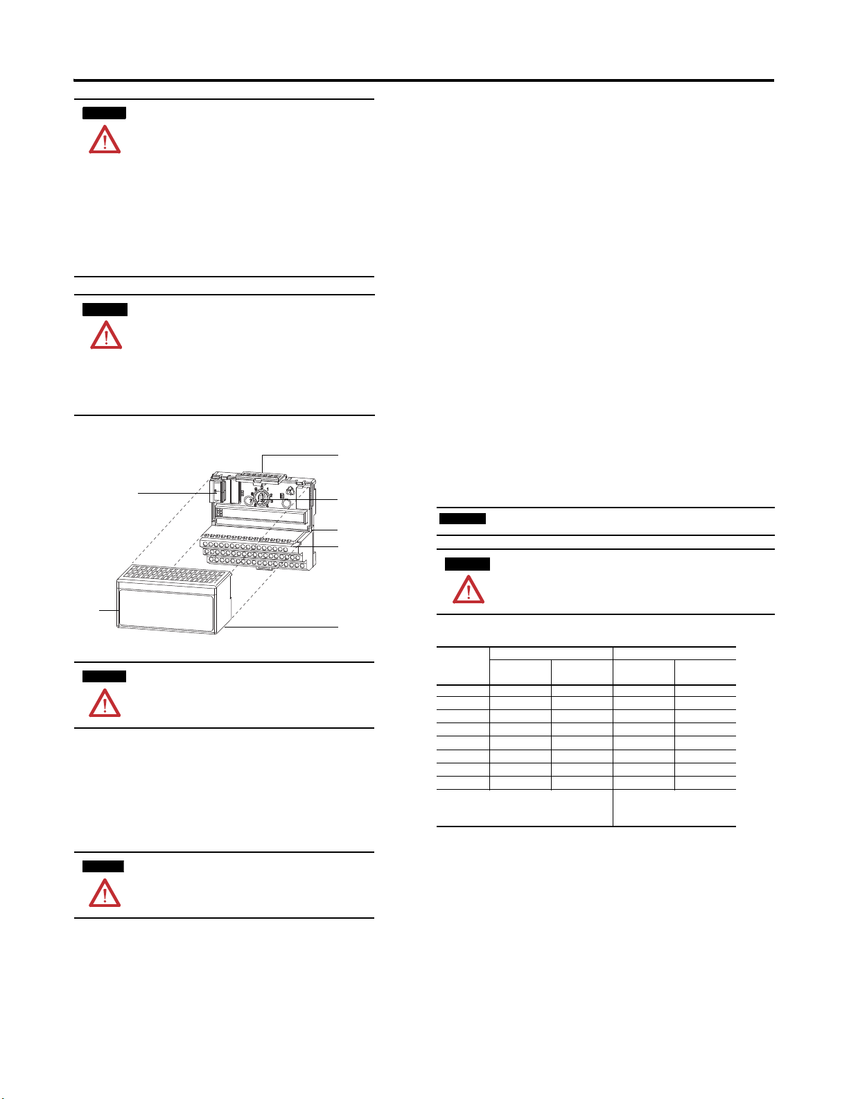
Install Your FLEX I/O AC Digital Output Module
5. Press firmly and evenly to seat the module in the terminal base unit. The
module is seated when the latching mechanism (2) is locked into the
module.
Connecting Wiring for the 1794-OA8 and 1794-OA8K
1. For 1794-TB2, 1794-TB3, or 1794-TB3S: Connect individual output
wiring to even numbered terminals on the 0…15 row (A) as indicated in
the table, Wiring Connections for the 1794-OA8 and 1794-OA8K.
For 1794-TBN or 1794-TBNF: Connect individual output wiring to even
numbered terminals on the 16…33 row (B) as indicated in the table below.
2. For 1794-TB2, 1794-TB3, or 1794-TB3S: Connect the associated V AC
common (L2) lead of the output device to the corresponding odd
numbered terminal on the 0…15 row (A) for each output as indicated in
the table below; or to the corresponding terminal on the 16…33 row (B).
(The V AC common (L2) terminals of row (B) and the odd numbered
terminals of row (A) are internally connected together.)
For 1794-TBN or 1794-TBNF: Connect the associated V AC common
(L2) lead of the output device to the corresponding odd numbered
terminal on the 34…51 row (C) for each output as indicated in the table
below. (The odd numbered terminals of row (C) are internally connected
together to V AC L2 common.)
3. Connect V AC power L1 to terminal 34 on the 34…51 row (C).
4.
Connect V AC common L2 to terminal 16 on the 16…33 row (B).
5. If daisychaining V AC power (L1) to the next terminal base, connect a
jumper from terminal 51 (V AC L1) on this base unit to ter minal 34 on the
next base unit.
6. If continuing V AC common (L2) to the next base unit, connect a jumper
from terminal 33 (V common L2) on this base unit to terminal 16 on the
next base unit.
Total current draw through terminal base connection is limited to 10A. Separate power
connections to each terminal base may be necessary.
The module mounts on a 1794 terminal base.
1794-TBNF and 1794-TBNFK are not approved f or Class I Division 2
Applications.
1. Rotate the keyswitch (3) on the terminal base (4) clockwise to position 8 as
required for this type of module.
2. Make certain the FlexBus connector (1) is pushed all the way to the left to
connect with the neighboring terminal base/adapter. You cannot install
the module unless the connector is fully extended.
3. Make sure the pins on the bottom of the module are straight so they will
align properly with the connector in the terminal base.
If you insert or remove the module while backplane power is on , an
electrical arc can occur. This could cause an explosion in hazardous location
installations. Be sure that power is rem oved or the area is nonhazardous
before proceeding.
4. Position the module (7) with its alignment bar (6) aligned with the groove
(5) on the terminal base.
If multiple power sources are used for 1794-OA8I, do n ot exceed the specified isolation
voltage.
Wiring Connections for the 1794-OA8 and 1794-OA8K
(1)
Output
0 A-0 A-1/B-17 B-0 C-1
1 A-2 A-3/B-19 B-2
2 A-4 A-5/B-21 B-4
3 A-6 A-7/B-23 B-6
4 A-8 A-9/B-25 B-8
5 A-10 A-11/B-27 B-10
6 A-12 A-13/B-29 B-12
7 A-14 A-15/B-31 B-14
A = Output terminals (Even numbered terminals 0…14)
B = Common terminals
C = Power terminals (C-34 and C-51 on 1794-TB2; C-34…C-51 on
1794-TB3 and 1794-TB3S)
(1)
(2)
1794-TB2, 1794-TB3, 1794-TB3S 1794-TBN, 1794-TBNF
Output Terminal Common
A-1, 3, 5, 7, 9, 11, 13 and 15 on the 1794-TB2, 1794-TB3 and 1794-TB3S are internally connected in the
module to 120V AC common (L2).
C-1, 3, 5, 7, 9, 11, 13 and 15 on the 1794-TBN and 1794-TBNF are internally connected in the module to
120V AC common (L2).
Terminal (L2)
Output Terminal Common
(1)
B = Even numbered output terminals 0…14, AC
common terminals 16 and 33
C = Power terminals C-34 and C-51, and odd
numbered output terminals 1…15
Terminal (L2)
C-3
C-5
C-7
C-9
C-11
C-13
C-15
(2)
Publication 1794-IN103B-EN-P - May 2011
Page 3

3
IMPORTANT
17 18 19 20 21 22 23 24 25 26 27 28 29 30 31 32 33
0 1 2 3 4 5 6 7 8 9 10 11 12 13 14 15
16
35 36 37 38 39 40 41 42 43 44 45 46 47 48 49 50 51
34
Commons
(1794-TB3 shown)
Connect 120V AC common L2 to terminal B-16.
Connect 120V AC power L1 to terminal C-34.
L2 IN L2 OUT
Voltage
A
B
C
(Use B-33 and C-51 for daisy-chaining power to the next terminal base unit.)
L1 IN L1 OUT
(Terminals C-35…C-50 are not present on the 1794-TB2.)
45671
16
0
1
2
3
4
5
6789101112
13
14
15
51
33
34
B
C
Even Numbered I/O Terminals 0…14
Odd Numbered I/O Terminals 1…15
Connect 120V AC (L2) to terminal B-16
Connect 120V AC power (L1) to terminal C-34
Use B-33 and C-51 for daisychaining to the next terminal base
L1
L2
L1
L2
45672
IMPORTANT
45673
45674
1794-TB2, 1794-TB3 and 1794-TB3S Terminal Base Wiring for the
1794-OA8
1794-TBN and 1794-TBNF Terminal Base Wiring for the 1794-OA8
Connecting Wiring for the 1794-OA8I
1. For 1794-TB2, 1794-TB3, or 1794-TB3S
the even numbered terminals on the 0…15 row (A).
For 1794-TBN or 1794-TBNF: Connect individual output wiring to the
even numbered terminals on the 16…33 row (B).
2. For 1794-TB2, 1794-TB3, or 1794-TB3S: Connect the associated V AC
power lead (L1) to the corresponding odd numbered terminal on the
0…15 row (A) for each output as indicated in the table below.
For 1794-TBN or 1794-TBNF: Connect the associated V AC pow er (L1)
lead to the odd numbered terminals on row (C).
Individual isolated 120V AC common (L2) lead s must be run externally to each
output device.
Wiring Connections for the 1794-OA8I
(1)
1794-TB2, 1794-TB3, 1794-TB3S 1794-TBN, 1794-TBNF
Output
Output
Terminal
0 A-0
1 A-2
2 A-4
3 A-6
4 A-8
5 A-10
6 A-12
7 A-14
(1)
A = Even numbered terminals 0…14 for customer connections; corresponding odd numbered 120V AC
supply L1 terminals 1…15 for customer connections from isolated power supply.
(2)
B = Even numbered terminals 0…14 for customer connections; C = Odd numbered 120V AC supply L1
terminals 1…15 for custome r connections from isolated power supply.
120V AC
Supply
A-1
A-3
A-5
A-7
A-9
A-11
A-13
A-15
(1)
: Connect individual output wiring to
Output
Terminal
B-0 C-1
B-2
B-4
B-6
B-8
B-10
B-12 C-13
B-14 C-15
120V AC
Supply
C-3
C-5
C-7
C-9
C-11
(2)
1794-TB2, 1794-TB3, 1794-TB3S Terminal Base Wiring for 1794-OA8I
0 1 2 3 4 5 6 7 8 9 10 11 12 13 14 15
17 18 19 20 21 22 23 24 25 26 27 28 29 30 31 32 33
16
35 36 37 38 39 40 41 42 43 44 45 46 47 48 49 50 51
34
Connect outputs to even numbered terminals on row (A)
Connect isolated 120V AC (L1) to odd numbered terminals on row (A)
Individual isolated 120V AC common (L2) must be run externally to each of the output devices
(Terminals C-35…C-50 are not available on the 1794-TB2.)
A
B
C
(1794-TB3 shown)
1794-TBN and 1794-TBNF Terminal Base Wiring for the 1794-OA8I
COM
16
Connect outputs to even numbered terminals on row (B).
Connect isolated 120V AC (L1) to odd numbered terminals on row (C).
Individual isolated 120V AC common (L2) must be run externally to each
of the output devices.
Even Numbered I/O Terminals 0...14
2
0
34
3
1
+V
Odd Numbered I/O Terminals 1...15
4
6789101112
5
COM
14
33
B
13
51
15
C
+V
Connecting Wiring for the 1794-OA16
1. For 1794-TB2, 1794-TB3, or 1794-TB3S: Connect individual output
wiring to numbered terminals on the 0…15 row (A) as indicated in the
table below.
For 17 94-TBN: Connect individual output wiring to terminals 0…15 on
rows B and C.
2. For 1794-TB2, 1794-TB3 or 1794-TB3S: Connect the associated V AC
common (L2) lead of the output device to the corresponding numbered
terminal on the 16…33 row (B) for each output as indicated in the table
below. (The V AC common terminals of row (B) are internally connected
together.)
For 17 94-TBN: Auxiliary terminal blocks are required to connect the
associated L2 common for each channel. Connect the L2 side of the load
together and then connect to L2 on the power supply.
3.
Connect 120V AC power L1 to terminal 34 on the 34…51 row (C).
4. Connect 120V AC common L2 to terminal 16 on the 16…33 row (B).
5. If daisychaining power to the next terminal base, connect a jumper from
terminal 51 (120V AC L1) on this base unit to terminal 34 on the next base
unit.
6. If continuing 120V AC common (L2) to the next base unit, connect a
jumper from terminal 33 (120V AC common L2) on this base unit to
terminal 16 on the next base unit.
Total current draw through terminal base connection is limited to 10 A.
Separate power connections to each terminal base may be necessar y.
Wiring Connections for 1794-OA16
Output
1794-TB2, 1794-TB3, 1794-TB3S 1794-TBN
Channel
Output Terminal 120V AC Common (L2)
0 A-0 B-17 B-0
1 A-1 B-18 C-1
2 A-2 B-19 B-2
3 A-3 B-20 C-3
4 A-4 B-21 B-4
5 A-5 B-22 C-5
6 A-6 B-23 B-6
7 A-7 B-24 C-7
8 A-8 B-25 B-8
9 A-9 B-26 C-9
Output Terminal
(1)
Publication 1794-IN103B-EN-P - May 2011
Page 4

4
17 18 19 20 21 22 23 24 25 26 27 28 29 30 31 32 33
0 1 2 3 4 5 6 7 8 9 10 11 12 13 14 15
16
35 36 37 38 39 40 41 42 43 44 45 46 47 48 49 50 51
34
Commons
(1794-TB3 shown)
Connect 120V AC common L2 to terminal B-16.
Connect 120V AC power L1 to terminal C-34.
L2 IN L2 OUT
Voltage
A
B
C
(Use B-33 and C-51 for daisy-chaining power to the next terminal base unit.)
L1 IN L1 OUT
(Terminals C-35…C-50 are not present on the 1794-TB2.)
Outputs
45675
16
0
1
2
3
4
5
6789101112
13
14
15
51
33
34
B
C
Even Numbered I/O Terminals 0…14
Odd Numbered I/O Terminals 1…15
Connect 120V AC (L2) to terminal B-16
Connect 120V AC power (L1) to terminal C-34
Use B-33 and C-51 for daisychaining to the next terminal base
L1
L2
L1
L2
45676
Wiring Connections for 1794-OA16
Output
1794-TB2, 1794-TB3, 1794-TB3S 1794-TBN
Channel
Output Terminal 120V AC Common (L2)
10 A-10 B-27 B-10
11 A-11 B-28 C-11
12 A-12 B-29 B-12
13 A-13 B-30 C-13
14 A-14 B-31 B-14
15 A-15 B-32 C-15
120V AC L1
Connect V AC L1 to C-34.
power
1794-TB3, 1794-TB3S – Power terminals C-34…C-51 are internally connected together.
1794-TB2 and 1794-TBN – C-34 and C-51 are internally connected together.
120V AC L2
Connect 120V AC common L2 to terminal B-16.
common
1794-TB3, 1794-TB3S – 120V AC common L2 terminals B-16…B-33 are internally connected together.
1794-TB2, 1794-TBN – 120V AC common L2 terminals B-16 and B-33 internally connected together.
(1)
Auxiliary terminal blocks are required to connect the associated L2 common for each channel when
using a 1794-TBN terminal base with the 1794-OA16.
Output Terminal
(1)
1794-TB2, 1794-TB3, 1794-TB3S Terminal Base Wiring for 1794-OA16
1794-TBN Terminal Base Wiring for 1794-OA16
Image Table Memory Map for the 1794-OA16
Dec 15 14 13 12 11 10 09 08 7 6 5 4 3 2 1 0
Oct 17 16 15 14 13 12 11 10 7 6 5 4 3 2 1 0
Read Not used - set to 0
Write O15 O14 O13 O12 O11 O10 O9 O8 O7 O6 O5 O4 O3 O2 O1 O0
Where: O = Output number
Specifications
Specifications for 1794-OA8, 1794-OA8K and 1794-OA8I
Attribute
Number of outputs 8, (1 group of 8), nonisolated 8, isolated
Module location 1794-TB2, 1794-TB3, 1794-TB3S, 1794-TBN and 1794-TBNF
Output voltage range 85V AC, min
Output current rating 4.0A (8 outputs @ 500 mA)
On-state current
Voltage drop,
on-state, max
Leakage current,
off-state, max
Surge current 7A for 40 ms, repeatable every 8 s
Output signal delay
Off to On
On to Off
Power dissipation, max
Thermal dissipation 14.0 BTU/hr @ 0.5 A
FlexBus current 80 mA @5V DC
(2)
Fusing
(1)
Output signal delay is the time from receipt of an output on or off command to the output actually
turning on or off.
(2)
Module outputs are not fused. Fusing is recommended. If fusing is desired, you must supply external
fusing or use the 179 4-TBNF terminal base, if recommended.
1794-OA8, 1794-OA8K 1794-OA8I
120V AC, nom
132V AC, max
5.0 mA per output min
500 mA per output max @ 55 °C (sufficient to operate an Allen-Bradley
Bulletin 500 NEMA size 3 motor starter)
750 mA per output max @ 35 °C
1.0A on 4 nonadjacent outputs, 500 mA on the remaining 4 outputs @ 30 °C
NOTE
: Below 50 mA the voltage drop across the module will be higher and
the voltage waveform may have some small oscillation (less than 5V).
1.0V @ 0.5A
2.25 mA
(1)
1/2 cycle, max
1/2 cycle, max
4.1W @ 0.5A
6.3W @ 0.75A
6.3W @ 1.0A
21.2 BTU/hr @ 0.75 A
21.4 BTU/hr @ 1.0 A
1.6A, 250V AC slow-blow, Littelfuse 23901.6; San-O SD6-1.6 (1.6A fuses
come preinstalled in 1794-TBNF terminal base un its.)
Configure the FLEX I/O AC Output Module
Image Table Memory Map for the 1794-OA8, 1794-OA8K and 1794-OA8I
Dec 15 14 13 12 11 10 9 8 7 6 5 4 3 2 1 0
Oct 17 16 15 14 13 12 11 10 7 6 5 4 3 2 1 0
Read Not used – set to 0
Write Not used – set to 0 O7 O6 O5 O4 O3 O2 O1 O0
Where: O = Output number
Publication 1794-IN103B-EN-P - May 2011
Specifications for 1794-OA16
Attribute
Number of outputs 16, nonisolated
Module location
Mounting See derating curve
Output voltage range 74V AC min, 47…63 Hz
Output current rating 4.0A (16 outputs @ 250 mA)
On-state current 5.0 mA per output, min
On-state voltage drop, max 1.5V @ 0.5 A
Off-state leakage current, max 2.25 mA
Surge current 7 A for 40 ms, repeatable every 8 s
Off to On
On to Off
(1)
Output signal delay
Power dissipation, max 4.7W @ 0.5A
Thermal dissipation 16.1 BTU/hr @ 0.5 A
FlexBus current 80 mA @ 5V DC
(2)
Fusing
Valu e
1794-TB2, 1794-TB3, 1794-TB3S and 1794 -TBN3
120V AC nom, 47…63 Hz
132V AC max, 47…63 Hz
Attention: If using 0.5A outputs, alternate wi ring so that no
two 0.5 A outputs are next to each other.
500 mA per output @ 55 °C, max
NOTE: Below 50 mA the voltage drop across the module will
be higher and the voltage waveform m ay have some small
oscillation (less than 5V).
1/2 cycle, max
1/2 cycle, max
2.5A, 150V AC normal blow, MQ2
(3)
Page 5

5
0
72
10 20 30 40 50 55 60
V
in
On-state
Voltage
(V AC)
Ambient Temperature
o
C
The area within the curve represents the safe operating range for the module under
various conditions of user supplied 120V AC supply voltages and ambient temperatures.
= Other mounting positions (including inverted horizontal, vertical)
safe operating range
80
88
96
102
110
115
120
132
51
= Normal mounting safe operating range. Includes
130
45677
(1)
Auxiliary terminal blocks are required to connect the associated 120V AC common for each channel
when using the 1794-TBN terminal base with the 1794-OA16.
(2)
Output signal delay is the time from receipt of an output on or off command to the output actually
turning on or off.
(3)
Module outputs are not fused. Fusing is recommended. If fusing is desired, you must supply external
fusing or use the 1794-TBNF terminal base, if recommended.
General Specifications
Attribute
Terminal base screw torque Determined by installed terminal base
Dimensions (with module
installed), HxWxD
Indicators (field side
indication, logic driven)
Supply voltage or
voltage ranges
Isolation voltage 120V (continuous), Basic Insulation Type, field side to backplane
Pilot Duty Rating 5 A Inrush
Keyswitch position 8
Enclosure type rating None (open-style)
North American Temp Code T4A – for 1794-OA8, 1794-OA8K, 1794- OA8I only
IEC temp code T4 – for 1794-OA8K only
Wire size Determined by installed terminal base
Wiring
(1)
Category
(1)
Use this Conductor Category information for planning conductor routing. Refer to Industrial Automation
Wiring and Grounding Guidelines, publication 1770-4.1
Environmental Specifications
Attribute Value
Temperature,
operating
Temperature,
nonoperating
Temperature,
surrounding air, max
Relative humidity IEC 60068-2-30 (Test Db, Unpackaged Damp Heat):
Vibration IEC60068-2-6 (Test Fc, Operating):
Shock, operating IEC 60068-2-27 (Test Ea, Unpackaged Shock):
Shock, nonoperating IEC 60068 -2-27 (Test Ea, Unpackaged Shock):
Emissions CISPR 11:
ESD immunity IEC 61000-4- 2:
Radiated RF
immunity
Vibration IE C 60068-2-6 (Test Fc, Operating):
EFT/B immunity IEC 61000-4-4:
IEC 60068-2-1 (Test Ad, Operating Cold),
IEC 60068-2-2 (Test Bd, Operating Dry Heat),
IEC 60068-2-14 (Test Nb, Operating Thermal Shock):
0…55 °C (32…131 °F)
IEC 60068-2-1 (Test Ab, Un-packaged Non-operating Cold),
IEC 60068-2-2 (Test Bb, Un-packaged Non-operating Dry Heat),
IEC 60068-2-14 (Test Na, Un-packaged Non-operating Thermal Shock):
-40…85 °C (-40…185 °F)
55 °C (131 °F)
5…95% noncondensing
5 g @ 10…500 Hz
30 g
50 g
Group 1, Class A (with appropriate enclosure)
4 kV contact discharges
8 kV air discharges
(1794-OA8, 1794-OA8K)
IEC 61000-4-3:
10V/m with 1 kHz sine-wave 80% AM fr om 30…2000 MHz
10V/m with 200 Hz 50% Pulse 100% AM @ 900 MHz
1V/m with 1 kHz sine-wave 80% AM from 2000…2700 MHz
(1794-OA8I)
IEC 61000-4-3:
10V/m with 1 kHz sine-wave 80% AM fr om 30…2000 MHz
1V/m with 1 kHz sine-wave 80% AM from 2000…2700 MHz
(1794-OA16)
IEC 61000-4-3:
10V/m with 1 kHz sine-wave 80% AM fr om 80…2000 MHz
10V/m with 200 Hz 50% Pulse 100% AM @ 900 MHz
10V/m with 200 Hz 50% Pulse 100% AM @ 1890 MHz
3V/m with 1 kHz sine-wave 80% AM from 2000…2700 MHz
5 g @ 10…500 Hz
±2 kV at 5 kHz on signal ports
Value
94 x 94 x 69 mm
(3.7 x 3.7 x 2.7 in.)
8 yellow status indicators – for 1794-OA8, 1794-OA8K
8 yellow status indicators – for 1794-OA8I
16 yellow status indicators – for 1794-OA16
FlexBus: 5V DC, 80 mA
Output: 120V AC, 50/60 Hz, 0.5 A, Pilot Duty, 4 A total
No isolation between individual channels
Type tested @ 1250V AC for 60 s
T4 – for 1794-OA16 only
2 – on signal ports
.
Environmental Specifications
Attribute Value
Surge transient
immunity
Conducted RF
immunity
Oscillatory surge
withstand
IEC 61000-4-5:
±1 kV line-line(DM) and ±2 kV line-earth(CM) on sig nal ports
(1794-OA8, 1794-OA8K, 1794-OA8I)
IEC 61000-4-6:
10V rms with 1 kHz sine-wave 80% AM from 150 kHz…30 MHz
(1794-OA16)
IEC 61000-4-6
10V rms with 1 kHz sine-wave 80% AM from 150 kHz…80 MHz
IEEE C37.90.1:
2.5 kV
Certifications
Certifications
(when product is
(1)
marked)
UL UL Listed Industrial Control Equipment. See U L File E65584.
CSA
(for 1794-OA8,
1794-OA8K, and
1794-OA8I only)
CSA
(for 1794-OA16 only)
CE European Union 2004/108/EC EMC Dire ctive, compliant with:
C-Tick Australian Radiocommunications Act, compliant with:
Ex
(for 1794-OA8K only)
(1)
See the Product Certi fication link at http://www.ab.com for Declaration s of Conformity, Certificates,
and other certification details.
Valu e
CSA Certified Process Control Equipment. See CSA File LR5468 9C.
CSA Certified Process Control Equipment for Class I, Division 2
Group A,B,C,D Hazardous Locations. See CSA File LR69960C.
CSA Certified Process Control Equipment. See CSA File LR9370 1.
CSA Certified Process Control Equipment for Class I, Division 2
Group A,B,C,D Hazardous Locations. See CSA File LR93701.
EN 61326-1; Meas./Control/Lab., Industr ial Requirements
EN 61000-6-2; Industrial Immu nity
EN 61000-6-4; Industrial Emissions
EN 61131-2; Programmable Controllers (Cl ause 8, Zone A & B)
European Union 2006/95/EC LVD, compliant with:
EN 61131-2; Programmable Controllers (Clause 11)
AS/NZS CISPR 11; Industrial Emissions
European Union 94/9/EC ATEX Directive, compliant with:
EN 60079-15; Potentially Explosive Atmospheres, Pr otection "n"
EN 60079-0; General Requirement s
II 3 G Ex nA nC IIC T4 X
Derating Curve for 1794-OA16
Mounting Temperature, max.
Normal horizontal 55 °C
Other mounting positions (including inve rted horizontal, vertical) 51 °C
Publication 1794-IN103B-EN-P - May 2011
Page 6
Rockwell Otomasyon Ticaret A.Ş., Kar Plaza İş Merkezi E Blok Kat:6 34752 İçerenköy, İstanbul, Tel: +90 (216) 5698400
Rockwell Automation Support
Rockwell Automation provides technical information on the Web to assist you in using its products.
At http://www.rockwellautomation.com/support/
application notes, sample code and links to software service packs, and a MySupport feature that you can customize to make the
best use of these tools.
For an additional level of technical phone support for installation, configuration, and troubleshooting, we offer TechConnect
support programs. For more information, contact your local distributor or Rockwell Automation representative,
or visit http://www.rockwellautomation.com/support/
Installation Assistance
If you experience a problem within the first 24 hours of installation, review the information that is contained in this manual.
You can contact Customer Support for initial help in getting your product up and running.
United States or Canada 1.440.646.3434
Outside United States or
Canada
Use the Worldwide Locator
your local Rockwell Automation representative.
, you can find technical manuals, a knowledge base of FAQs, technical and
.
at http://www.rockwellautomation.com/support/americas/phone_en.html, or contact
New Product Satisfaction Return
Rockwell Automation tests all of its products to ensure that they are fully operational when shipped from the manufacturing facility.
However, if your product is not functioning and needs to be returned, follow these procedures.
United States Contact your distributor. You must provide a Customer Support case number (call the phone number above to obtain
Outside United States Please contact your local Rockwell Automation representative for the return procedure.
one) to your distributor to complete the return process.
Documentation Feedback
You r co mme nts will help us serve your documentation needs better. If you have any suggestions on how to improve this document,
complete this form, publication RA-DU002
, available at http://www.rockwellautomation.com/literature/.
Publication 1794-IN103B-EN-P - May 2011 PN-113124
Supersedes publication - 1794-IN103A -EN-P - June 204 Copyright © 2011 Rockwell Automation, In c. All rights reserved. Printed in the U.S.A.
 Loading...