

Page 1

Installation Instructions
FlexLogix Controller System
Catalog numbers 1794-L33, 1794-L34, 1794-FLA
Use this document as a guide for installing your FlexLogix™ controller system. This
document provides installation instructions for both the FlexLogix controller
(1794-L33, -L34) and the FlexLogix extended-local I/O adapter (1794-FLA). You
should already be familiar with the FlexLogix system components. See the
documentation references for additional information.
You must FLASH upgrade the firmware on your FlexLogix controller before you
can use it. The controller ships with firmware revision 1.x but must be upgraded to
match the version of RSLogix 5000 that you are using (e.g. if you are using
RSLogix 5000 V11, you must upgrade your FlexLogix controller firmware to revision
11.x before using it). For more information on upgrading your controller’s
firmware, see page 22.
Tools That You Need
You need the following tools to install your FlexLogix controller system.
• slotted screwdriver
• phillips screwdriver
• mounting hardware (for mounting a DIN rail)
• drill (for mounting a DIN rail)
• needle-nose pliers
Obtain a User Manual
This product also has a user manual (pub. no. 1794-UM001). To view it, visit:
www.theautomationbookstore.com. To purchase a manual, you can:
• contact your local distributor or Rockwell Automation representative
• visit www.theautomationbookstore.com and place an order
• call 800.963.9548 (USA/Canada) or 001.320.725.1574 (outside USA/Canada)
Publication 1794-IN002G-EN-P - January 2004
Page 2
2 FlexLogix Controller System
Important User Information
Solid state equipment has operational characteristics differing from those of electromechanical equipment.
Safety Guidelines for the Application, Installation and Maintenance of Solid State Controls (Publication
SGI-1.1 available from your local Rockwell Automation sales office or online at
http://www.ab.com/manuals/gi) describes some important differences between solid state equipment and
hard-wired electromechanical devices. Because of this difference, and also because of the wide variety of
uses for solid state equipment, all persons responsible for applying this equipment must satisfy themselves
that each intended application of this equipment is acceptable.
In no event will Rockwell Automation, Inc. be responsible or liable for indirect or consequential damages
resulting from the use or application of this equipment.
The examples and diagrams in this manual are included solely for illustrative purposes. Because of the many
variables and requirements associated with any particular installation, Rockwell Automation, Inc. cannot
assume responsibility or liability for actual use based on the examples and diagrams.
No patent liability is assumed by Rockwell Automation, Inc. with respect to use of information, circuits,
equipment, or software described in this manual.
Reproduction of the contents of this manual, in whole or in part, without written permission of Rockwell
Automation, Inc. is prohibited.
Throughout this manual we use notes to make you aware of safety considerations.
WARNING
Identifies information about practices or circumstances that can cause an explosion in a
hazardous environment, which may lead to personal injury or death, property damage,
or economic loss.
IMPORTANT
ATTENTION
SHOCK HAZARD
BURN HAZARD
Identifies information that is critical for successful application and understanding of the
product.
Identifies information about practices or circumstances that can lead to personal injury
or death, property damage, or economic loss. Attentions help you:
• identify a hazard
• avoid a hazard
• recognize the consequence
Labels may be located on or inside the drive to alert people that dangerous voltage may
be present.
Labels may be located on or inside the drive to alert people that surfaces may be
dangerous temperatures.
Publication 1794-IN002G-EN-P - January 2004
Page 3
Environment and Enclosure
FlexLogix Controller System 3
ATTENTION
This equipment is intended for use in a Pollution Degree 2
industrial environment, in overvoltage Category II applications
(as defined in IEC publication 60664-1), at altitudes up to 2000
meters without derating.
This equipment is considered Group 1, Class A industrial
equipment according to IEC/CISPR Publication 11. Without
appropriate precautions, there may be potential difficulties
ensuring electromagnetic compatibility in other environments
due to conducted as well as radiated disturbance.
This equipment is supplied as "open type" equipment. It must be
mounted within an enclosure that is suitably designed for those
specific environmental conditions that will be present and
appropriately designed to prevent personal injury resulting from
accessibility to live parts. The interior of the enclosure must be
accessible only by the use of a tool. Subsequent sections of this
publication may contain additional information regarding specific
enclosure type ratings that are required to comply with certain
product safety certifications.
NOTE: See NEMA Standards publication 250 and IEC publication
60529, as applicable, for explanations of the degrees of
protection provided by different types of enclosure. Also, see the
appropriate sections in this publication, as well as the
Allen-Bradley publication 1770-4.1 ("Industrial Automation
Wiring and Grounding Guidelines"), for additional installation
requirements pertaining to this equipment.
Prevent Electrostatic Discharge
ATTENTION
This equipment is sensitive to electrostatic discharge, which can
cause internal damage and affect normal operation. Follow these
guidelines when you handle this equipment:
• Touch a grounded object to discharge potential static.
• Wear an approved grounding wriststrap.
• Do not touch connectors or pins on component boards.
• Do not touch circuit components inside the equipment.
• If available, use a static-safe workstation.
• When not in use, store the equipment in appropriate
static-safe packaging.
Publication 1794-IN002G-EN-P - January 2004
Page 4
4 FlexLogix Controller System
European Hazardous Location Approval
European Zone 2 Certification (The following applies when the product
bears the EEx Marking)
This equipment is intended for use in potentially explosive atmospheres as
defined by European Union Directive 94/9/EC.
The LCIE (Laboratoire Central des Industries Electriques) certifies that this
equipment has been found to comply with the Essential Health and Safety
Requirements relating to the design and construction of Category 3 equipment
intended for use in potentially explosive atmospheres, given in Annex II to this
Directive. The examination and test results are recorded in confidential report
No. 28 682 010.
Compliance with the Essential Health and Safety Requirements has been
assured by compliance with EN 50021.
IMPORTANT
When using this product, also consider the following:
• This equipment is not resistant to sunlight or other
sources of UV radiation.
• The secondary of a current transformer shall not be
open-circuited when applied in Class I, Zone 2
environments.
• Equipment of lesser Enclosure Type Rating must be
installed in an enclosure providing at least IP54 protection
when applied in Class I, Zone 2 environments.
• This equipment shall be used within its specified ratings
defined by Allen-Bradley.
• Provision shall be made to prevent the rated voltage from
being exceeded by transient disturbances of more than
40% when applied in Class I, Zone 2 environments.
Publication 1794-IN002G-EN-P - January 2004
Page 5
FlexLogix Controller System 5
North American Hazardous Location Approval
The following information applies
when operating this equipment in
hazardous locations:
Products marked “CL I, DIV 2, GP A,
B, C, D” are suitable for use in Class I
Division 2 Groups A, B, C, D,
Hazardous Locations and
nonhazardous locations only. Each
product is supplied with markings on
the rating nameplate indicating the
hazardous location temperature code.
When combining products within a
system, the most adverse temperature
code (lowest “T” number) may be
used to help determine the overall
temperature code of the system.
Combinations of equipment in your
system are subject to investigation by
the local Authority Having
Jurisdiction at the time of installation.
Informations sur l’utilisation de
cet équipement en
environnements dangereux :
Les produits marqués "CL I, DIV 2,
GP A, B, C, D" ne conviennent qu’à
une utilisation en environnements de
Classe I Division 2 Groupes A, B, C,
D dangereux et non dangereux.
Chaque produit est livré avec des
marquages sur sa plaque
d’identification qui indiquent le code
de température pour les
environnements dangereux. Lorsque
plusieurs produits sont combinés
dans un système, le code de
température le plus défavorable
(code de température le plus faible)
peut être utilisé pour déterminer le
code de température global du
système. Les combinaisons
d’équipements dans le système sont
sujettes à inspection par les autorités
locales qualifiées au moment de
l’installation.
Publication 1794-IN002G-EN-P - January 2004
Page 6
6 FlexLogix Controller System
The following information applies
when operating this equipment in
hazardous locations:
WARNING
EXPLOSION
HAZARD
• Do not disconnect
equipment unless
power has been
removed or the
area is known to
be nonhazardous.
• Do not disconnect
connections to this
equipment unless
power has been
removed or the
area is known to
be nonhazardous.
Secure any external
connections that
mate to this
equipment by
using screws,
sliding latches,
threaded
connectors, or
other means
provided with this
product.
• Substitution of
components may
impair suitability
for Class I, Division
2.
• If this product
contains batteries,
they must only be
changed in an area
known to be
nonhazardous.
Informations sur l’utilisation de
cet équipement en
environnements dangereux :
AVERTISSEMENT
RISQUE
D’EXPLOSION
• Couper le courant
ou s’assurer que
l’environnement est
classé non
dangereux avant de
débrancher
l'équipement.
• Couper le courant
ou s'assurer que
l’environnement est
classé non
dangereux avant de
débrancher les
connecteurs. Fixer
tous les
connecteurs
externes reliés à cet
équipement à l'aide
de vis, loquets
coulissants,
connecteurs filetés
ou autres moyens
fournis avec ce
produit.
• La substitution de
composants peut
rendre cet
équipement
inadapté à une
utilisation en
environnement de
Classe I, Division 2.
• S’assurer que
l’environnement est
classé non
dangereux avant de
changer les piles.
Publication 1794-IN002G-EN-P - January 2004
Page 7
FlexLogix Controller System 7
Removal and Insertion Under Power
The FlexLogix controller, the extended-local I/O adapter, the communication
daughtercards, and the I/O terminal bases cannot be removed or inserted
under power..
However, you can remove and insert FLEX I/O modules while backplane power is
applied and the system is operating.
WARNING
Be sure that power is removed or the area is nonhazardous before proceeding.
If you insert or remove the module while backplane power is
on, an electrical arc can occur. This could cause an explosion
in hazardous location installations.
Other Considerations
ATTENTION
Also consider the following before you install your
FlexLogix controller:
• This product is grounded through the DIN rail to chassis
ground. Use zinc plated yellow-chromate steel DIN rail to
assure proper grounding. The use of other DIN rail materials
(e.g. aluminum, plastic, etc.) that can corrode, oxidize, or are
poor conductors, can result in improper or intermittent
grounding.
• Power connection length should be less than 10 meters.
Publication 1794-IN002G-EN-P - January 2004
Page 8

8 FlexLogix Controller System
What You Need to Do
Before you can install a FlexLogix controller or extended-local adapter, you must:
Install steel, 35 x 7.55mm DIN rails (A-B part number 199-DR1; 46277-3)
✓
where you want to place the FlexLogix system components.
The DIN rails for all FlexLogix system components, including all local and
extended-local I/O modules, must be mounted on a common, conductive
surface to ensure proper electromagnetic interference (EMI) performance.
See 24 and 25 for approximate mounting dimensions and mounting
clearances.
For more information about mounting DIN rails and splitting I/O across DIN
rails, see the FLEX I/O Product Data, publication 1794-2.1
Use DIN rail locks (A-B catalog number 1492-EA35) to meet the shock and
✓
vibrations specifications listed on 26. A pair of DIN locks comes with
the controller.
Mount an appropriate power supply on an appropriate DIN rail. See the
✓
specifications on 26.
To install a FlexLogix controller:
Step 1: Verify That You Have All the Components, see page 9.
Step 2: Install the Battery, see page 10.
Step 3: Install Communication Daughtercards (optional), see page 11
Step 4: Install the Controller, see page 12.
Step 5: Install the Extended-Local Adapter (optional), see page 15.
After you install the FlexLogix controller, you can:
Make an RS-232 Connection to the Controller, see page 18.
Select the Operating Mode of the Controller see page 21.
Monitor the Controller LEDs, see page 22.
Publication 1794-IN002G-EN-P - January 2004
Page 9
FlexLogix Controller System 9
Step 1: Verify That You Have All the Components
These components ship with the FlexLogix controller:
• 1756-BA1 battery and label
• key
• one spring-clip connector plug for 24V power connection
• one screw-terminal connector plug for 24V power connection
• two 1492-EA35 DIN rail locks
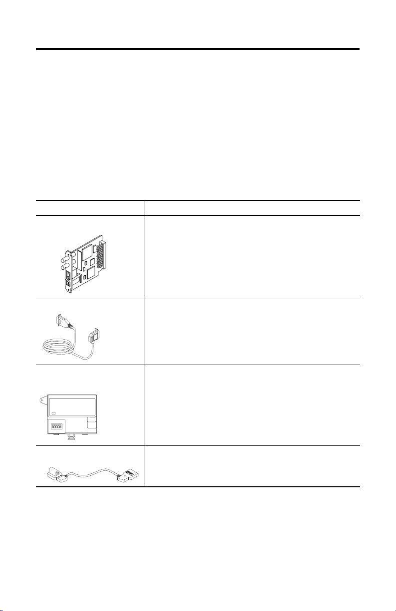
The system components you have depend on your application. You might have:
FlexLogix System Component: Description:
communication card
1788-CNC, -CNCR for ControlNet communications
1788-CNF, -CNFR for ControlNet communications
1788-DNBO for DeviceNet communications
1788-ENBT for EtherNet/IP communications
serial cable
FlexLogix extended-local
adapter
extended- local I/O cable
1756-CP3
You can also use the 1747-CP3 cable from the SLC product family.
1794-FLA
1794-CE1 (1 foot)
1794-CE3 (3 foot)
Publication 1794-IN002G-EN-P - January 2004
Page 10

10 FlexLogix Controller System
Step 2: Install the Battery
ATTENTION
WARNING
Only install a 1756-BA1 battery. If you install a different battery,
you may damage the controller.
For safety information on the handling of lithium batteries, including the handling and disposal of leaking batteries, see Guide-
lines for Handling Lithium Batteries, publication AG-5.4.
Store batteries in a cool, dry environment. We recommend 25°C
with 40% to 60% relative humidity. You may store batteries for
up to 30 days between -45° to 85°C, such as during transportation. To avoid possible leakage, do not store batteries above 60°C
for more than 30 days.
When you connect or disconnect the battery an electrical arc can
occur. This could cause an explosion in hazardous location installations. Be sure that power is removed or the area is nonhazardous before proceeding.
For Safety information on the handling of lithium batteries, including handling and
disposal of leaking batteries, see Guidelines for Handling Lithium Batteries,
publication AG 5-4.
1. Install a 1756-BA1 battery.
Attach label here.
This jumper is for service use
only. Do not use this jumper.
Attach battery here.
top red lead (+)
middle black lead (-)
bottom no connection
2. Attach the battery label:
a. Write on the battery label the date you install the battery.
b. Attach the label to the inside of the battery compartment.
Publication 1794-IN002G-EN-P - January 2004
Page 11

FlexLogix Controller System 11
Step 3: Install Communication Daughtercards (optional)
WARNING
For specific information about configuring the communication card (such as setting
a node address), see the installation instructions for the communication card.
1. Turn off power to the controller.
2. If necessary, remove the blank cover from the communication slot.
3. Slide the communication card into the communication slot. Be sure to line
up the card with the card guides in the controller.
4. Record which slot you use for the communication card. You need the slot
number when you develop your controller application.
5. Secure the card with the screws to ensure proper grounding. Do not
over-tighten the screws. The maximum torque for the card screws is 4.8 to
5.2 inch pounds (0.5 to 0.6 Nm)
6. After the controller is installed (see page 12), connect the network cable.
If you insert or remove the card while host power is on, an
electrical arc can occur. This could cause an explosion in hazardous location installations.
slot 1
slot 2
31032-M
Removing a Communication Card
If you need to remove a communication card from the controller:
1. Turn off power to the controller.
2. Disconnect all cables from the communication card.
3. Loosen the card screws from the communication card.
4. Remove the card from the controller.
5. Replace the card with a blank cover or a different communication card.
Publication 1794-IN002G-EN-P - January 2004
Page 12

12 FlexLogix Controller System
Step 4: Install the Controller
1. Position the FlexLogix controller on the DIN rail at a 5° angle and rotate the
controller onto the DIN rail.
A
A
locking tabs
IMPORTANT
You can mount the FlexLogix controller either vertically or
horizontally (as shown).
2. Press the controller down onto the DIN rail until flush. The locking tabs will
snap into position and lock the controller onto the DIN rail.
If the controller does not lock in place, use a screwdriver or similar device to
move the locking tabs down while pressing the controller onto the DIN rail.
Release the locking tabs to lock the controller in place. If necessary, push up
on the locking tabs to lock.
3. Ground the controller. The DIN rail and the common, conductive surface
behind the DIN rail provide functional ground for the controller. Use the
grounding stud to meet safety ground requirements.
grounding stud
nuts with captive
star washer
Equipment grounding conductor (ground lug
with 2.08 sq. mm [#14 AWG] wire) to ground bus
For information about wiring and grounding, see the Industrial Automation
Wiring and Grounding Guidelines publication 1770-4.1.
Publication 1794-IN002G-EN-P - January 2004
Page 13

FlexLogix Controller System 13
4. Make sure power is not applied to the power supply.
5. Connect the power supply to the controller. The graphic below and its
related instructions describe a 1794-PS13 power supply.
WARNING
If you connect or disconnect wiring while the field-side power
is on, an electrical arc can occur. This could cause an explosion
in hazardous location installations. Be sure that power is removed or the area is nonhazardous before proceeding.
+
_
+
_
A
B
C
D
FE
HG
a. Connect +24V dc input to the top of the controller connector, terminal A,
to the bottom, left power connector, terminal G.
b. Connect -24V common to top controller connector, terminal B, to the top,
left power connector, terminal E.
c. Use connections C and D on the controller and connection F and H on
the power supply to pass 24V dc power and common to the next module
in the series, if required.
Use the screw-terminal connector plug that comes with the controller to
meet the requirements for installations in Class I, Division 2 locations.
Publication 1794-IN002G-EN-P - January 2004
Page 14

14 FlexLogix Controller System
6. Mount the I/O terminal bases on the DIN rail.
A
B
A
31036-M
For information about I/O terminal bases, see the FLEX I/O Terminal Base
Installation Instructions, publication 1794-IN092.
7. Install the I/O modules.
To install an I/O module, see the installation instructions for that module.
Removing the controller
If you need to remove the controller, follow these steps:
1. Turn off power to the controller.
2. Disconnect all cables from the controller.
3. Remove the I/O module that is adjacent to the controller.
4. On the terminal base adjacent to the controller, slide the FLEXBUS connector
away from the controller and remove the I/O terminal base.
5. Remove the controller from the DIN rail.
Publication 1794-IN002G-EN-P - January 2004
Page 15

FlexLogix Controller System 15
Step 5: Install the Extended-Local Adapter (optional)
1. Position the 1794-FLA extended-local I/O adapter on the DIN rail at a 30°
angle and rotate the adapter onto the DIN rail.
2. Press the adapter down onto the DIN rail until flush. The locking tab will
snap into position and lock the adapter onto the DIN rail.
If the adapter does not lock in place, use a screwdriver or similar device to
move the locking tab down while pressing the adapter onto the DIN rail.
Release the locking tab to lock the adapter in place. If necessary, push up on
the locking tab to lock.
3. Ground the adapter. The adapter is grounded through the steel DIN rail and
the common, conductive surface behind the DIN rail. Additionally, use the
grounding stud.
grounding stud
nuts with captive
star washer
Equipment grounding conductor (ground lug with
2.08 sq. mm [#14 AWG] wire) to ground bus
Publication 1794-IN002G-EN-P - January 2004
Page 16

16 FlexLogix Controller System
4. Make sure power is not applied to the power supply. Connect the
power supply to the adapter. This diagram and its related instructions
describe a 1794-PS13 power supply.
a. Connect +24V dc input to the left adapter connector, terminal A, to the
bottom, left power connector, terminal G.
b. Connect -24V common to left adapter connector, terminal B, to the top,
left power connector, terminal E.
c. Use connections C and D on the adapter and connection F and H on the
power supply to pass 24V dc power and common to the next module in
the series, if required.
Use the screw-terminal connector plug that comes with the adapter to meet
the requirements for installations in Class I, Division 2 locations.
5. Connect I/O terminal bases and I/O modules to the adapter the same way
you connect them to the controller.
6. Remove the plastic spacer from both ends of the extended-local I/O cable
(1794-CE1 or 1794-CE3).
plastic spacer
Publication 1794-IN002G-EN-P - January 2004
Page 17

7. Connect the adapter to the controller.
FlexLogix Controller System 17
1794-CE1 or
1794-CE3 cable
LOCAL2 rail
31039-M
The following diagram shows how you can also use the 1794-CE1, -CE3
cable to split a rail of I/O. You can split each rail only once. You can split a
rail right after the controller (or adapter) or after any I/O module. For more
information about the 1794-CE1, -CE3 cables, see the Interconnect Cable
Installation Instructions, publication 1794-5.12.
1794-CE1 or
1794-CE3 cable
LOCAL rail
1794-CE1 or
1794-CE3 cable
1794-CE1 or
1794-CE3 cable
Removing the extended-local adapter
If you need to remove the adapter, follow these steps:
1. Turn off power to the adapter.
2. Disconnect all cables from the adapter.
3. Remove the I/O module that is adjacent to the adapter.
4. On the terminal base adjacent to the adapter, slide the FLEXBUS connector
away from the adapter and remove the I/O terminal base.
5. Remove the adapter from the DIN rail.
Publication 1794-IN002G-EN-P - January 2004
Page 18

18 FlexLogix Controller System
Make an RS-232 Connection to the Controller
The RS-232 port is a non-isolated serial port built-in to the front of the controller.
serial port
To connect to the serial port:
1. Determine whether you need an optical isolator.
If you connect the controller to a device outside of the system’s enclosure,
consider installing an isolator between the controller and device.
One possible isolator is the 1761-NET-AIC interface converter.
baud rate selector switch
port 1: DB-9 RS-232, DTE
Publication 1794-IN002G-EN-P - January 2004
port 2: mini-DIN 8 RS-232
dc power source selector switch
terminals for external 24V
dc power supply
Page 19
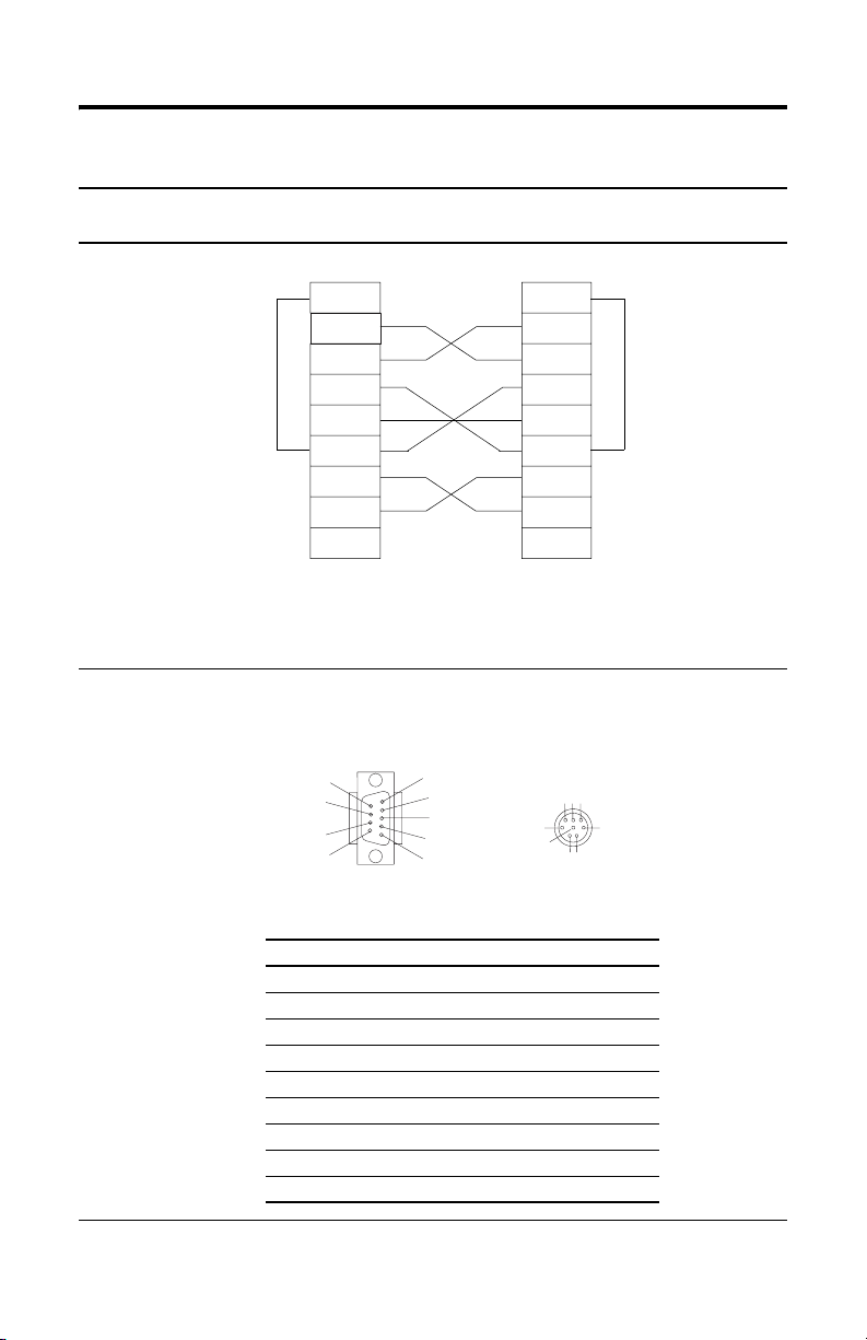
2. Select the appropriate cable.
5
8
Are you using
an isolator?
no The 1756-CP3 cable attaches the controller directly to the controller.
Use this cable:
FlexLogix Controller System 19
1 CD
2 RDX
3 TXD
4 DTR
COMMON
6 DSR
7 RTS
8 CTS
9
1 CD
2 RDX
3 TXD
4 DTR
COMMON
6 DSR
7 RTS
8 CTS
9
If you make your own cable, it must be shielded and the shields must be tied to the metal
shell (that surrounds the pins) on both ends of the cable.
You can also use a 1747-CP3 cable (from the SLC product family). This cable has a taller
right-angle connector housing than the 1756-CP3 cable.
yes The 1761-CBL-AP00 cable (right-angle connector to controller) or the 1761-CBL-PM02 cable
(straight connector to the controller) attaches the controller to port 2 on the 1761-NET-AIC
isolator. The mini-DIN connector is not commercially available, so you cannot make
this cable.
6
7
9
1
2
3
4
5
678
3
4
12
DB-9 right-angle or straight cable end 8-pin, mini-DIN cable end
Pin: DB-9 end: Mini-DIN end:
1DCD DCD
2RxD RxD
3TxD TxD
4DTR DTR
5 ground ground
6DSR DSR
7RTS RTS
8CTS CTS
9na na
Publication 1794-IN002G-EN-P - January 2004
Page 20

20 FlexLogix Controller System
3. Connect the appropriate cable to the serial port on the controller.
WARNING
Be sure that power is removed or the area is nonhazardous before
proceeding.
4. If necessary, attach the controller to the isolator.
If you connect or disconnect the serial cable with power
applied to this module or the serial device on the other end of
the cable, an electrical arc can occur. This could cause an
explosion in hazardous location installations.
system enclosure
1761 cable
1761-NET-AIC
isolator
user-supplied modem cable
Publication 1794-IN002G-EN-P - January 2004
modem
Page 21

FlexLogix Controller System 21
Select the Operating Mode of the Controller
1. Use this table to determine the operating mode of the controller:
If you want to: Select one of these modes:
Run Program Remote
Run Program Test
turn outputs to the state commanded by
the logic of the project
turn outputs to their configured state for
Program mode
execute (scan) tasks YES YES YES
change the mode of the controller
through software
download a project YES YES
schedule a ControlNet network YES YES
while online, edit the project YES YES YES YES
2. Turn the key on the front panel of the controller to select the mode.
YES YES
YES YES YES
YES YES YES
keyswitch
To select: Turn the key to:
Remote Run RUN and then to REM
Remote Program PROG and then to REM
Remote Test REM and then go online and select Test mode via the programming software
Publication 1794-IN002G-EN-P - January 2004
Page 22

22 FlexLogix Controller System
Monitor the Controller LEDs
Indicator: Color: Description:
RUN off
green
OK off no power applied
red flashing after initially installing the controller - the controller requires a
red
green controller OK
BATTERY off battery will support memory
red
I/O off
green communicating to all devices
green flashing one or more devices are not responding
LOCAL
and
LOCAL2
RS232 off no activity
FORCE off no forces present
off rail is inhibited
green communicating to all devices on that rail
green flashing one or more devices on that rail not responding
red flashing no modules exist on that rail
green data being received or transmitted
amber forces present
• no task(s) running
• controller in Program mode
• one or more tasks are running
• controller is in Run mode
FLASH upgrade to the proper firmware revision; see below.
after the controller is operating - recoverable fault
• controller faulted
• clear faults, clear memory, or replace the controller
• battery may not support memory
• replace battery
• controller project not downloaded (the condition after power up)
• no I/O or communications configured
FLASH Upgrade the Controller’s Firmware Revision
To update the firmware of a controller, first install a firmware upgrade kit.
• An upgrade kit ships on a supplemental CD along with RSLogix 5000
software.
• To download an upgrade kit, go to http://support.rockwellautomation.com.
Choose Firmware Updates.
Publication 1794-IN002G-EN-P - January 2004
Page 23
Update the Controller
FlexLogix Controller System 23
TIP
1. Connect the controller to the same network as your workstation.
2. Start ControlFLASH software.
3. Choose N
4. Select the catalog number of the controller and choose Next >.
5. Expand the network until you see the controller. If the required network is
not shown, first configure a driver for the network in RSLinx software.
6. Select the controller and choose OK.
RSLogix 5000 software, revision 10.0 or later, lets you update
controller firmware as part of the download sequence. To
update the controller, download your project and follow the
prompts of the software.
ext >.
42900
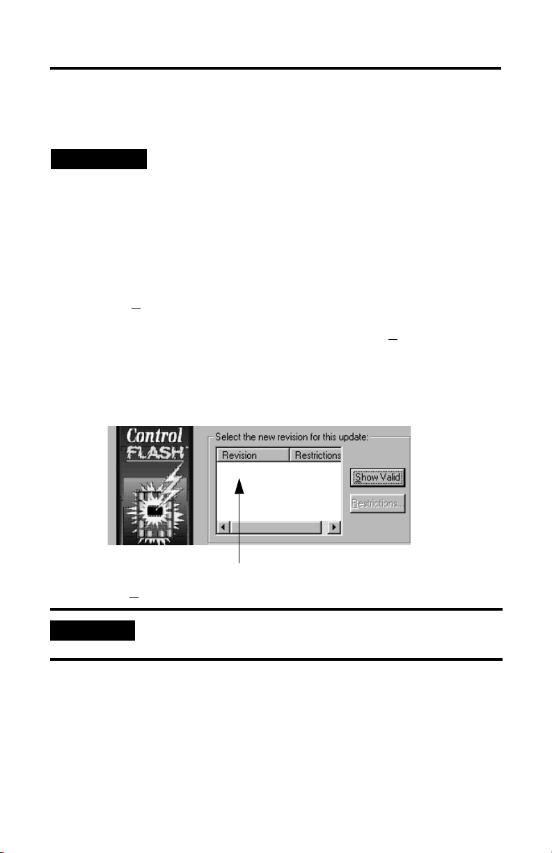
7. Select the revision level to which you want to update the controller and
choose N
IMPORTANT
8. To start the update of the controller, choose Finish and then Yes.
After the controller is updated, the status box displays Update complete.
9. Choose OK.
10. To close ControlFLASH software, choose Cancel and then Yes.
ext >.
If the Revision list is empty, download a new upgrade kit. Some
older upgrade kits do not work with new controllers.
Publication 1794-IN002G-EN-P - January 2004
Page 24

24 FlexLogix Controller System
FlexLogix Controller Approximate Mounting Dimensions
104.57mm (4.12in)
8.85mm
(0.35in)
199.49mm (7.85in)
185.3mm (7.30in)
84.9mm (3.34in)
50.43mm
(1.99in)
6.4mm
(0.25in)
6.0mm
(0.24in)
121.97mm
(4.81in)
101.6mm
(4.00in)
13.5mm
(0.53in)
182.96mm (7.203in)
88.57mm
(3.49in)
87.24mm
(3.43in)
80.14mm
(3.16in)
92.96mm
(3.66in)
88.57mm
(3.49in)
8.25mm
(0.33in)
105.96mm
(4.17in)
centerline of
64.36mm
(2.53in)
centerline
of DIN rail
101.49mm
(3.99in)
MTG Hole
Publication 1794-IN002G-EN-P - January 2004
Page 25

FlexLogix Controller System 25
FlexLogix Extended-Local I/O Adapter Approximate Mounting Dimensions
94mm
(3.7in)
117.12mm
(4.61in)
88.94mm
(3.5in)
Approximate Mounting Clearance
25.4 mm (1 in)
25.4 mm (1 in)
25.4 mm (1 in)
25.4 mm (1 in)
69mm
(2.72in)
81.06mm
(3.19in)
25.4 mm (1 in)
25.4 mm (1 in)
25.4 mm (1 in)
Publication 1794-IN002G-EN-P - January 2004
Page 26

26 FlexLogix Controller System
Other Publications
You can use the following manuals with this product:
Documents required for installation details: Publication number:
Industrial Automation Wiring and Grounding Guidelines 1770-4.1
Flex 1794-PS3 Power Supply Installation Instructions 1794-5.71
Flex 1794-PS13 Power Supply Installation Instructions 1794-5.69
Flex I/O Terminal Base Installation Instructions 1794-5.16
1794-CE1, -CE3 Interconnect Cable Installation Instructions 1794-5.12
FLEX I/O and FLEX Integra I/O Technical Data 1794-2.1
Documents available for further reference Publication number:
FlexLogix System User Manual 1794-UM001
Logix5000 Controllers Common Procedures Reference Manual 1756-PM001
Logix5000 Controllers General Instruction Set Reference Manual 1756-RM003
Guidelines for Handling Lithium Batteries AG-5.4
You can obtain manuals at www.theautomationbookstore.com.
Specifications
Category: FlexLogix controller
user memory 1794-L33 64 KBytes
input voltage
rating (nominal)
range
isolation voltage
(continuous-voltage
withstand rating)
input current
power dissipation
backplane (FLEXBUS)
current output
thermal dissipation 87BTU/hour @ 19.2V 25.6BTU/hour @ 19.2V
weight 1794-L33 .71 kg (1.56 lbs oz.)
(1)
(2)
(1794-L33, -L34)
1794-L34 512 KBytes
24V dc
19.2V to 31.2V dc (includes 5% ac ripple)
30V dc
Qualification tested to withstand 850V dc for 60 seconds
1.33A maximum at 19.2V dc
0.85A maximum at 24V dc
25.5W maximum at 19.2V
20.4W maximum at 24V dc
653mA maximum @ 5.1V dc 653mA maximum @ 5.1V dc
1794-L34 .75 g (1.66 lbs.)
(no communication cards installed)
FlexLogix extended-local I/O
adapter (1794-FLA)
na
0.39A maximum at 19.2V dc
0.25A maximum at 24V dc
7.5W maximum at 19.2V
6.0W maximum at 24V dc
.28 kg (.62 lbs.)
Publication 1794-IN002G-EN-P - January 2004
Page 27

FlexLogix Controller System 27
Category: FlexLogix controller
(1794-L33, -L34)
FlexLogix extended-local I/O
adapter (1794-FLA)
power supply 1794-PS3 or 1794-PS13 – In applications that must be compliant with CSA
!
requirements, use a Separated Extra-Low Voltage (SELV) power supply that is
compliant with IEC 61010.1, Annex H
power conductors 60° C (140° F) minimum, copper
#22 to #14 AWG (0.324 to 2.08 sq. mm) stranded
3/64 inch (1.2mm) insulation maximum
length 10m or less
category 3
(2)
power connector torque 5 to 7 inch-pounds (0.6 to 0.8Nm)
battery 1756-BA1 (AB part number 94194801)
na
0.59g lithium
serial cable 1761-CBLPM02 to 1761-NET-AIC
na
1761-CBLPA00 to 1761-NET-AIC
1756-CP3 directly to controller
1747-CP3 directly to controller
category 3
(4)
extended local I/O cable 1794-CE1 cable (1 foot)
1794-CE3 cable (3 feet)
category 3
(2)
DIN rail steel, 35 x 7.55mm DIN rail
A-B part number 199-DR1; 46277-3; EN 50022
operating temperature IEC 60068-2-1 (Test Ad, Operating Cold),
IEC 60068-2-2 (Test Bd, Operating Dry Heat),
IEC 60068-2-14 (Test Nb, Operating Thermal Shock):
0 to 60°C (32 to 140°F)
storage temperature IEC 60068-2-1 (Test Ab, Un-packaged Non-operating Cold),
IEC 60068-2-2 (Test Bb, Un-packaged Non-operating Dry Heat),
IEC 60068-2-14 (Test Na, Un-packaged Non-operating Thermal Shock):
–40 to 85°C (–40 to 185°F)
relative humidity IEC 60068-2-30 (Test Db, Un-packaged Non-operating Damp Heat):
5 to 95% non-condensing
vibration
(3)
shock
(3)
operating
non-operating
IEC60068-2-6 (Test Fc, Operating): 5g @ 10-500Hz
IEC60068-2-27: (Test Ea, Unpackaged shock):
30g
50g
emissions CISPR 11:
Group 1, Class A (with appropriate enclosure)
ESD immunity IEC 61000-4-2:
6kV contact discharges
8kV air discharges
Publication 1794-IN002G-EN-P - January 2004
Page 28

Category: FlexLogix controller
(1794-L33, -L34)
FlexLogix extended-local I/O
adapter (1794-FLA)
radiated RF immunity IEC 61000-4-3:
10V/m with 1kHz sine-wave 80%AM from 30MHz to 2000MHz
10V/m with 200Hz 50% Pulse 100%AM at 900Mhz
EFT/B immunity IEC 61000-4-4:
±4kV at 2.5kHz on power ports
±2kV at 5kHz on communications ports
surge transient immunity IEC 61000-4-5:
±2kV line-earth (CM) on shielded ports
conducted RF immunity IEC 61000-4-6:
10Vrms with 1kHz sine-wave 80%AM from 150kHz to 80MHz
enclosure type rating none (open-style)
Certifications:
(when product is marked)
UL UL Listed Industrial Control Equipment
c-UL-us UL Listed for Class I, Division 2 Group A,B,C,D Hazardous
Locations, certified for U.S. and Canada
CSA CSA Certified Process Control Equipment
CSA CSA Certified Process Control Equipment for Class I, Division 2
Group A,B,C,D Hazardous Locations
(5)
CE
European Union 89/336/EEC EMC Directive, compliant with:
EN 50082-2; Industrial Immunity
EN 61326; Meas./Control/Lab., Industrial Requirements
EN 61000-6-2; Industrial Immunity
EN 61000-6-4; Industrial Emissions
(5)
C-Tick
Australian Radiocommunications Act, compliant with:
AS/NZS CISPR 11; Industrial Emissions
(5)
EEx
European Union 94/9/EEC ATEX Directive, compliant with:
EN 50021; Potentially Explosive Atmospheres, Protection "n"
(Zone 2)
(1)
This specification is also known as Power Consumption.
(2)
This specification is also known as Heat Dissipation.
(3)
To maintain these vibration and shock specifications, you must use DIN rail locks.
(4)
Use this Conductor Category information for planning conductor routing. Refer to Publication 1770-4.1, "Industrial
Automation Wiring and Grounding Guidelines".
(5)
See the Product Certification link at www.ab.com for Declarations of Conformity, Certificates, and other certification
details.
Publication 1794-IN002G-EN-P - January 2004 PN 957867-01
Supersedes Pub lication 1794-IN002F-E N-P - October 2002 Copyright © 20 04 Rockwell Automatio n, Inc. All rights reser ved. Printed in the U.S.A.
 Loading...