

Page 1
Installation Instructions
FLEX I/O Remote I/O Adapter Module
1794-ASBLT Series D
WARNING
Important User Information
Solid state equipment has operational characteristics differing from those of
electromechanical equipment. Safety Guidelines for the Application, Installation and
Maintenance of Solid State Controls (Publication SGI-1.1 available from your local
Rockwell Automation sales office or online at
http://www.literature.rockwellautomation.com) describes some important differences
between solid state equipment and hard-wired electromechanical devices. Because of
this difference, and also because of the wide variety of uses for solid state equipment, all
persons responsible for applying this equipment must satisfy themselves that each
intended application of this equipment is acceptable.
In no event will Rockwell Automation, Inc. be responsible or liable for indirect or
consequential damages resulting from the use or application of this equipment.
The examples and diagrams in this manual are included solely for illustrative purposes.
Because of the many variables and requirements associated with any particular
installation, Rockwell Automation, Inc. cannot assume responsibility or liability for actual
use based on the examples and diagrams.
No patent liability is assumed by Rockwell Automation, Inc. with respect to use of
information, circuits, equipment, or software described in this manual.
Reproduction of the contents of this manual, in whole or in part, without written
permission of Rockwell Automation, Inc. is prohibited.
Throughout this manual we use notes to make you aware of safety considerations.
WARNING
IMPORTANT
ATTENTION
SHOCK HAZARD
Use the 1794-ASBLT Series D adapter when
communicating with Classic PLC-5/15 or
PLC-5/25 via Remote I/O. The 1794-ASBLT
Series D adapter is a replacement for the
1794-ASB Series D adapter only when
communicating with PLC-5/15 or PLC5/25.
Identifies information about practices or circumstances that can
cause an explosion in a hazardous environment, which may lead
to personal injury or death, property damage, or economic loss.
Identifies information that is critical for successful application
and understanding of the product.
Identifies information about practices or circumstances that can
lead to personal injury or death, property damage, or economic
loss. Attentions help you:
• identify a hazard
• avoid a hazard
• recognize the consequence
Labels may be located on or inside the equipment (e.g., drive or
motor) to alert people that dangerous voltage may be present.
ATTENTION
WARNING
WARNING
ATTENTION
ATTENTION
Environment and Enclosure
This equipment is intended for use in a Pollution Deg ree 2 industrial
environment, in overvoltage Category II applications (as defined in
IEC publication 60664-1), at altitudes up to 2000 meters without
derating.
This equipment is considered Group 1, Class A industrial equipment
according to IEC/CISPR Publication 11. Without appropriate
precautions, there may be potential difficulties ensuring
electromagnetic compatibility in other environments due to
conducted as well as radiated disturbance.
This equipment is supplied as "open type" equipment. It must be
mounted within an enclosure that is suitably designed for those
specific environmental conditions that will be present and
appropriately designed to prevent personal injury resulting from
accessibility to live parts. The interior of the enclosure must be
accessible only by the use of a tool. Subsequent sections of this
publication may contain additional information regarding specific
enclosure type ratings that are required to comply with certain
product safety certifications.
See NEMA Standards publication 250 and IEC publication 60529, as
applicable, for explanations of the degrees of protection provided by
different types of enclosure. Also, see the appropriate sections in this
publication, as well as the Allen-Bradley publication 1770-4.1
("Industrial Automation Wiring and Grounding Guidelines"), for
additional installation requirements pertaining to this equipment.
When you insert or remove the module while backplane power is on,
or connect or disconnect the serial cable with power applied to this
module or the serial device on the other end of the cable, an
electrical arc can occur. This could cause an explosion in hazardous
location installations. Be sure that power is removed or the area is
nonhazardous before proceeding.
If you connect or disconnect wiring while the field-side power is on,
an electrical arc can occur. This could cause an explosion in
hazardous location installations. Be sure that power is removed or
the area is nonhazardous before proceeding.
FLEX I/O is grounded through the DIN rail to chassis ground. Use
zinc plated yellow-chromate steel DIN rail to assure proper
grounding. The use of other DIN rail materials (e.g. aluminum,
plastic, etc.) that can corrode, oxidize, or are poor conductors, can
result in improper or intermittent grounding.
Preventing Electrostatic Discharge
This equipment is sensitive to electrostatic discharge, which can
cause internal damage and affect normal operation. Follow these
guidelines when you handle this equipment:
• Touch a grounded object to discharge potential static.
• Wear an approved grounding wriststrap.
• Do not touch connectors or pins on component boards.
• Do not touch circuit components inside the equipment.
• If available, use a static-safe workstation.
BURN HAZARD
Labels may be located on or inside the equipment (e.g., drive or
motor) to alert people that surfaces may be dangerous
temperat ures.
Publication 1794-IN110A-EN-P - August 2005
Page 2
2
A
North American Hazardous Location Approval
The following information applies when
operating this equipment in hazardous
locations:
Products marked “ CL I, DIV 2, GP A, B, C, D” are
suitable for use in C lass I Division 2 Groups A, B, C,
D, Hazardous Locations and nonhazar dous locations
only. Each product is supp lied with markings on the
rating namepla te indicating the ha zardous location
temperature co de. When combining produ cts within
a system, the most adverse temperature code
(lowest “T” number ) may be used to help deter mine
the overall temperatur e code of the system.
Combinations of equipment in your sys tem are
subject to investiga tion by the local Authority
Having Jurisdic tion at the time of in stallation.
WARNING
EXPLOSION HAZARD
• Do not disconnect
equipment unless power has
been remove d or the area is
known to be nonha zardous.
• Do not disconnect
connections to this equipment
unless power has been
removed or the area is known
to be nonhazard ous. Secure
any external connections that
mate to this eq uipment by
using screws, sliding latches,
threaded connectors, or other
means provided with this
product.
• Substitution of components
may impair suitability for Class
I, Division 2.
• If this product contains
batteries, they must only be
changed in an ar ea known to
be nonhazardous .
Informations sur l’utilisation de cet équipement en
environnements dangereux :
Les produits marq ués "CL I, DIV 2, GP A, B, C, D " ne
conviennent qu’à une utilisation en environnements de
Classe I Division 2 Groupes A, B, C, D d angereux et non
dangereux. Chaq ue produit est livré avec des marquages sur
sa plaque d’iden tification qui indiqu ent le code de
température pour les environnements dangereux. Lorsque
plusieurs produits sont combinés dans un système, le code
de température le plus défavorable (code de température le
plus faible) peut ê tre utilisé pour détermine r le code de
température global du syst ème. Les combinaisons
d’équipements dans le système sont su jettes à inspection
par les autorités locales qualifiées au moment de
l’installation.
VERTISSEME NT
RISQUE D’EXPLOSION
• Couper le cour ant ou s’assurer
que l’environnem ent est classé
non dangereux a vant de
débrancher l'éq uipement.
• Couper le cour ant ou s'assurer
que l’environnem ent est classé
non dangereux a vant de
débrancher les connecteurs. Fixer
tous les con necteurs externes
reliés à cet équip ement à l'aide de
vis, loquets coulissants,
connecteurs filetés ou autres
moyens fournis avec ce produit.
• La substitution de composants
peut rendre c et équipement
inadapté à une ut ilisation en
environnement de Classe I,
Division 2.
• S’assurer que l’ environnement
est classé non dan gereux avant de
changer les piles.
Remote I/O Adapter, Cat. No. 1794-ASBLT Series D
These adapters are shipped configured for standard addressing mode. In
Standard Addressing Mode, the 1794-ASBLT series D adapter can be used as a
replacement for 1794-ASB series A and B remote I/O adapters.
1
2
1794-ASBLT
3
4, 5
6
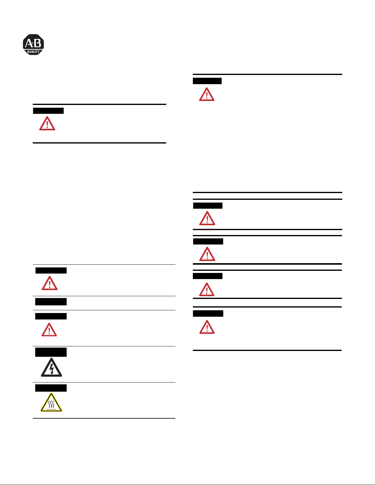
Component Identification
1 Remote I/O Adapter Module
2 Indicators
3 Communication reset button (PRL)
4 Access door to switches S1 and S2
5 Switches S1 and S2 (behind door)
6 Remote I/O cable connector
7 +V dc connections
8 -V common connections
9 Flexbus connector
9
8
7
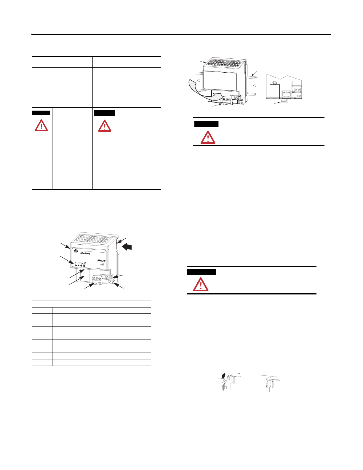
Install Your Adapter Module
A
B
C
ATTENTION
During mounting of all devices, be sure that all
debris (such as metal chips or wire strands) is kept
from falling into the module. Debris that falls into
the module could cause damage on power up.
Mount on a DIN Rail Before Installing the Terminal Base Units
1. Hook the lip on the rear of the adapter onto the top of the DIN rail,
and rotate the adapter module onto the rail.
2. Press the adapter module down onto the DIN rail until flush. Locking
tab C will snap into position and lock the adapter module to the DIN
rail.
3. If the adapter module does not lock in place, use a screwdriver or
similar device to move the locking tab down while pressing the
adapter module flush onto the DIN rail, and release the locking tab to
lock the adapter module in place. If necessary, push up on the locking
tab to lock.
4. Connect the adapter wiring as shown under “Wiring” later in this
document.
Mount (or Replace) the Adapter on an Existing System
1. Remove the RIO plug-in connector from the front of the adapter.
2. Disconnect any wiring jumpered to the adjacent terminal base.
WARNING
3. Open the module latching mechanism and remove the module from
the base unit to which the adapter will be attached.
4. Push the flexbus connector toward the right side of the terminal base
to unplug the backplane connection. (When fully retracted, you will
see a raised dot on the connector.)
5. Release the adapter locking tab and remove the adapter module.
6. Before installing the new adapter, notice the notch on the right rear of
the adapter. This notch accepts the hook on the terminal base unit.
The notch is open at the bottom. The hook and adjacent connection
point keep the terminal base and the adapter tight together, reducing
the possibility of a break in communication over the backplane.
If you connect or disconnect wiring while the field-side
power is on, an electrical arc can occur. This could cause
an explosion in hazardous location installations. Be sure
that power is removed or the area is nonhazardous before
proceeding.
C
7. Complete the adapter mounting as shown below.
Publication 1794-IN110A-EN-P - August 2005
Page 3

3
Push down and in at the same
time to lock the adapter to the
DIN rail.
C
When the adapter is locked onto the DIN
rail, gently push the flexbus connector into
the adapter to complete the backplane
20127
8. If the adapter module does not lock in place, use a screwdriver or
similar device to move the locking tab down while pressing the
adapter module flush onto the DIN rail, and release the locking tab to
lock the adapter module in place. If necessary, push up on the locking
tab to lock.
9. Reinstall the module in the adjacent terminal base unit.
Connect Wiring
WARNING
1. Connect the remote I/O cable to the removable remote I/O
ATTENTION
1SH2
If you connect or disconnect the communications
cable with power applied to this module or any
device on the network, an electrical arc can occur.
This could cause an explosion in hazardous location
installations.
connector.
Connect To terminal
Blue Wire - RIO 1
Shield Wire - RIO SH
Clear Wire - RIO 2
If this is the last adapter, you must terminate the
remote I/O link here. Use a terminating resistor
connected across terminals 1 and 2. Refer to your
processor manual for information on the size of the
resistor.
Allen-Bradley
ADAPTER
LOCAL
ACTIVE FAULT
FAULT
PWR
Termination resistor (if required)
82 W or 150 W (refer to your
processor documentation for size and usage)
1794-ASBLT
B
A
COM
24V
20131_LT
ATTENTION
To reduce susceptibility to noise, power analog
modules and digital modules from separate power
supplies. Do not exceed a total length of 32.8 ft
(10m) for dc power cabling.
Set the Addressing Mode Switches
87654321
87654321
Flip
open
cover
ATTENTION
on
on
S1
S2
Some switches on this adapter differ from the
switches on previous versions. Make certain that
you identify each switch before setting.
1. Lift the hinged switch cover on the front of the adapter to expose the
switches.
2. Set the switches as shown below.
3. Cycle power to the adapter after setting the switches.
8 and 16-point Mode Switch Settings
When using this
addressing
mode
Standard (as
shipped
Compact 8-point modules OFF ON OFF
Complementary See complementary table below.
Primary Chassis 8-point modules OFF OFF ON
Complementary
Chassis
Complementary See complementary table below.
Primary Chassis 16-point modules OFF OFF OFF
Complementary
Chassis
1 In Standard mode, this switch retains its function as switch position 1 of
C
D
rack addressing. In standard mode, the module is functionally
interchangeable with 1794-ASB series A or B adapters.
2 In compact mode, 32-point modules appear as 8 or 16-point modules.
3 When programming block transfers, address analog modules as module 0
if switch S1-1 is on; module 1 if switch S1-1 is off.
And Mode
8 and/or 16-point
modules
Switch 2
S1-1
See note 1ON ON
Mode
Switch 1
S2-5
Mode
Switch 0
S2-8
16-point modules ON ON OFF
ON OFF ON
ON OFF OFF
2. Connect +V dc power to the left side of the lower connector, terminal
A.
3. Connect -V common to the left side of the upper connector, terminal
B.
4. Connections C and D are used to pass +V dc power (D) and -V
common (C) to the next module in the series (if required).
Publication 1794-IN110A-EN-P - August 2005
Page 4

4
Mode Switch 0
First I/O
Group
I/O Rack
Number
Mode Switch 2
87654321
S1 S2
First I/O Group
S1-8 S1-7 I/O Group S1-6 thru S1-1
ON ON 0 (1st) Refer to addressing
OFF ON 2 (2nd)
ON OFF 4 (3rd)
OFF OFF 6 (4th)
87654321
Hold Inputs
Rack Fault Select
Mode Switch 1
Communication Rate Switches
Processor Restart Lockout
Hold Last State
onon
I/O Rack Number
mode tables.
Complementary I/O Rack Number Switch Settings for PLC-5
Processors
Refer to your processor documentation for all other
processors.
Primary Rack
Rack
Number
PLC-5/15 PLC-5/25
Not Valid Not Valid ON ON ON ON ON OFF
Rack 1 Rack 1 OFF ON ON ON ON OFF
Rack 2 Rack 2 ON OFF ON ON ON OFF
Rack 3 Rack 3 OFF OFF ON ON ON OFF
Rack
S1 Switch Position
Number
6 5 4 3 2 1
Rack 4 ON ON OFF ON ON OFF
Rack 5 OFF ON OFF ON ON OFF
Rack 6 ON OFF OFF ON ON OFF
Rack 7 OFF OFF OFF ON ON OFF
S2-8 Mode Switch 0
Refer to mode selection switches, above.
S2-7 Hold Inputs S2-6 Rack Fault Select
ON Hold inputs ON Disabled (default)
OFF Reset inputs OFF Enabled
S2-5 Mode Switch 1
Refer to mode selection switches, above.
Communication Rate Processor
Hold Last State
Restart Lockout
S2-4 S2-3 Bits/s S2-2 S2-1
ON ON 57.6 k ON Restart ON Reset Outputs
OFF ON
ON OFF
OFF OFF
1
PLC5/15 and PLC5/25 can only support 57.6 kbps.
115.2 k
230.4 k
230.4 k
1
OFF Locked out OFF Hold Last State
1
1
I/O Rack Number Switch Settings
Rack Number S1 Switch Position
PLC5/15 PLC-5/25 6 5 4 3 2 1
Not Valid Rack 0 ON ON ON ON ON ON
Rack 0 Rack 1 OFF ON ON ON ON ON
Rack 1 Rack 2 ON OFF ON ON ON ON
Rack 2 Rack 3 ON ON OFF ON ON ON
Rack 3 Rack 4 ON ON ON OFF ON ON
Rack 5 OFF ON OFF ON ON ON
Rack 6 ON OFF OFF ON ON ON
Rack 7 OFF OFF OFF ON ON ON
Complementary Rack
Rack
Number
PLC-5/15 PLC-5/25
Not Valid Not Valid ON ON ON OFF ON ON
Rack 1 Rack 1 OFF ON ON OFF ON ON
Rack 2 Rack 2 ON OFF ON OFF ON ON
Rack 3 Rack 3 OFF OFF ON OFF ON ON
Refer to your processor documentation for all other processors.
Rack
S1 Switch Position
Number
6 5 4 3 2 1
Rack 4 ON ON OFF OFF ON ON
Rack 5 OFF ON OFF OFF ON ON
Rack 6 ON OFF OFF OFF ON ON
Rack 7 OFF OFF OFF OFF ON ON
Publication 1794-IN110A-EN-P - August 2005
Page 5

5
Specifications
Specifications - Remote I/O Adapter, Cat. No. 1794-ASBLT/D
I/O Capacity 8 modules
Power Supply Power supply must be cap able of providing a turn-on inrush surge
Input Voltage Rating 24V dc nominal
Communication Rate 57.6 kbps
Indicators Power - green
Flexbus Output Current 640 mA maximum
Isolation Voltage 50V continuous
Current Draw 330 m A at 24V dc; 450 mA maximum
Power Dissipation 4.6 W maximum @ 31.2V dc
Thermal Dissipation Maximum 1.7 BTU/hr @ 31.2V dc
General Specifications
Dimensions 3.4H x 2.7W x 2.7D inches
Environmental Conditions
Operating Temperature IEC 60068-2-1 (Test Ad, Operating Cold),
Storage Temperature IEC 60068-2-1 (Test Ab, Unpackaged Nonoperating Cold),
Relative Humidity IEC 600 68-2-30 (Test Db, Unpackaged Nonoperating
Vibration IEC60068-2-6 (Test Fc, Operating):
Shock IEC60068-2-27 (Test Ea, Unpackaged shock):
Emissions CISPR 11:
ESD Immunity IEC 61000-4-2:
Radiated RF Immunity IEC 61000- 4-3:
EFT/B Immunity IEC 61000-4-4:
Surge Transient
Immunity
Conducted RF Immunity IEC 61000-4-6:
Enclosure Type Rating None (open-style)
Conductors Wire Size
Category
Terminal Screw Torque 7 pound-inches (0.8 Nm)
Remote I/O Cable Belden 9463 as specifie d in publication ICCG-2.2
current of 23 A (at 24V dc) for 2 ms for each adapter connected to
the power supply.
19.2V to 31.2 V dc (includes 5% ac rippl e)
115.2 kbps
230 kbps
NOTE: PLC5/15 and PLC5/25 can only support 57.6 kbps
Adapter Active - green
Adapter Fault - red
Local Fault - red
Tested at 850V dc for 1 s between user power and flexbus
87H x 69W x 69D mm
IEC 60068-2-2 (Test Bd, Operating Dry Heat),
IEC 60068-2-14 (Test Nb, Operating Thermal Shock):
0 to 55 °C (32 to 131 °F)
IEC 60068-2-2 (Test Bb, Unpackaged Nonoperating Dry Heat),
IEC 60068-2-14 (Test Na, Unpackaged Nonoperating Therma l
Shock):
–40 to 85 °C (–40 to 185 °F)
Damp Heat):
5 to 95% non-condensing
5g @ 10-500 Hz
Operating 30g
Non-operating 50g
Group 1, Class A (with appropriate e nclosure)
4 kV contact discharges
8 kV air discharges
10V/m with 1kHz sine-wave 80%AM f rom 30MHz to 2000MHz
10V/m with 200Hz 50% Pulse 100%A M at 900Mhz
10V/m with 200Hz 50% Pulse 100%A M at 1890Mhz
±2 kV at 5 kHz on power ports
±2 kV at 5 kHz on communications ports
IEC 61000-4-5:
±2 kV line-earth(CM) on commu nications ports
10Vrms with 1 kHz sine-wave 80%A M from 150 kHz to 80 MHz
Communications:
12 AWG (2.5mm2) …22 AWG (0.34mm2) solid or stranded copper
wire rated at 75°C or greater, 3/64 inch (1.2mm) insulation
maximum.
Power:
12 AWG (2.5mm2) …22 AWG (0.34mm2) solid or stranded copper
wire rated at 75°C or greater, 3/64 inch (1.2mm) insulation
maximum."
1
2 on communication ports
3 on power ports
Remote I/O connector Plug Part Number 942029- 03
Certifications (when
product is marked)
1 You use this ca tegory information fo r planning conductor routing as described in Allen-Bradley
publication 177 0-4.1, Industrial Autom ation Wiring and Groundin g Guidelines.
2 For the latest up-to-date informa tion, see the Product C ertification link at ww w.ab.com for Declaration s of
Conformity, Certificate s and other certification de tails.
CULUS UL Listed Industrial Control Equi pment, certified for US
2
and Canada
CULUS UL Listed for Class I, Divisi on 2, Groups A, B, C and D
Hazardous locations, cer tified for US and Canada
CSA CSA certified Process Control Equipment
CSA CSA certified Process Control Equipment for Class I ,
Division 2, Groups A, B, C and D Ha zardous locations
CE European Union 89/336/EEC EMC Directive,
compliant with:
EN 61000-6-4; Industrial Emissio ns
EN 50082-2; Industrial Immu nity
EN 61326; Meas./Control/Lab., Indu strial Requirements
EN 61000-6-2; Industrial Immunity
C-Tick Australian Radiocommunicati ons Act compliant with
AS/NZS CISPR 11, Industrial Emissions
Mounting Dimensions
Inches
(Millimeters
)
.83 (21)
3.2
(80)
3.4
(87)
A
= Mounting hole dimensions for optional wall/panel mounting kit
B
= DIN rail
= Secure DIN rail approximately every 200mm
C
(
A
1.4
(35)
2.7
(68)
1794-ASBLT/D
3.4H x 2.7W x 2.7D
(87H x 68W x 69D)
1794-ASBLT
(59)
2.3
2.0
(50)
1.2
(30)
B
C
Publication 1794-IN110A-EN-P - August 2005
Page 6

Publication 1794-IN110A-EN-P - August 2005 6 PN 957974-12
Copyright © 2005 Rockwell Automation, Inc . All rights reserved. Printed in the U.S.A.
 Loading...