

Page 1

User Manual
FLEX I/O Dual Port EtherNet/IP Adapter Modules
Catalog Numbers
1794-AENTR, 1794-AENTRXT
Page 2
Important User Information
IMPORTANT
Solid-state equipment has operational characteristics differing from those of electromechanical equipment. Safety
Guidelines for the Application, Installation and Maintenance of Solid State Controls (publication SGI-1.1
your local Rockwell Automation sales office or online at http://www.rockwellautomation.com/literature/
important differences between solid-state equipment and hard-wired electromechanical devices. Because of this difference,
and also because of the wide variety of uses for solid-state equipment, all persons responsible for applying this equipment
must satisfy themselves that each intended application of this equipment is acceptable.
In no event will Rockwell Automation, Inc. be responsible or liable for indirect or consequential damages resulting from
the use or application of this equipment.
The examples and diagrams in this manual are included solely for illustrative purposes. Because of the many variables and
requirements associated with any particular installation, Rockwell Automation, Inc. cannot assume responsibility or
liability for actual use based on the examples and diagrams.
No patent liability is assumed by Rockwell Automation, Inc. with respect to use of information, circuits, equipment, or
software described in this manual.
Reproduction of the contents of this manual, in whole or in part, without written permission of Rockwell Automation,
Inc., is prohibited.
Throughout this manual, when necessary, we use notes to make you aware of safety considerations.
WARNING: Identifies information about practices or circumstances that can cause an explosion in a hazardous
environment, which may lead to personal injury or death, property damage, or economic loss.
available from
) describes some
ATTENTION: Identifies information about practices or circumstances that can lead to personal injury or death,
property damage, or economic loss. Attentions help you identify a hazard, avoid a hazard, and recognize the
consequence
SHOCK HAZARD: Labels may be on or inside the equipment, for example, a drive or motor, to alert people that
dangerous voltage may be present.
BURN HAZARD: Labels may be on or inside the equipment, for example, a drive or motor, to alert people that
surfaces may reach dangerous temperatures.
Identifies information that is critical for successful application and understanding of the product.
Allen-Bradley, Rockwell Automation, FLEX I/O, ControlLogix, RSlogix, R SLinx, and TechConnect are trademarks of Rockwell Automation, Inc.
Trademarks not belonging to Rockwell Automation are property of their respective companies.
Page 3

Preface
Read this preface to familiarize yourself with the rest of the manual. It provides
information concerning:
• who should use this manual
• the purpose of this manual
• related documentation
• conventions used in this manual
Who Should Use this Manual
Purpose of this Manual
This manual is intended for control engineers and technicians who are installing,
configuring, and maintaining a redundant EtherNet/IP control system that
communicates with FLEX I/O through a 1794-AENTR or 1794-AENTRXT
adapter.
We assume you have a good understanding of Ethernet and the TCP/IP protocol.
If you do not, refer to your software user manuals or online help before
attempting to use these modules.
This manual describes how you can use your FLEX I/O EtherNet/IP adapter
with your controller. The manual helps you install, program, and troubleshoot
your module.
For Information About See
Overview of FLEX I/O and Your Redundant EtherNet/IP Adapter
Module
Install Your FLEX I/O Adapter Chapter 2
Configure the Adapter for Your EtherNet/IP Network Chapter 3
Rack Optimized Discrete I/O Chapter 4
Analog I/O with Direct Connection Chapter 5
Chapter 1
Interpret Status Indicators Appendix A
Specifications Appendix B
Configure the RSLinx Ethernet Communication Driver Appendix C
Adapter Web Dialogs Appendix D
iii Publication 1794-UM066A-EN-P - February 2012
Page 4

iv Preface
Related Documentation
The following documents contain additional information concerning Rockwell
Automation products.
Resource Description
FLEX I/O Selection Guide, publication 1794-SG002
FLEX I/O Dual Port EtherNet/IP Adapter Modules,
publication 1794-IN131
ControlLogix System User Manual,
publication 1756-UM001
FLEX I/O DC Power Supply Installation Instructions,
publication 1794-IN069
EtherNet/IP Embedded Switch Technology Application
Guide, publication ENET-AP005
EtherNet/IP Modules in Logix5000 Control Systems User
Manual, publication ENET-UM001
Interconnect Cable Installation Instructions, publication
1794-5.12
Industrial Automation Wiring and Grounding Guidelines,
publication 1770-4.1
Allen-Bradley Industrial Automation Glossary,
publication AG-7.1
You can view or download publications at
http://www.rockwellautomation.com/literature/
technical documentation, contact your local Rockwell Automation distributor or
sales representative.
A description and overview of the 1794 series FLEX I/O, FLEX I/O XT and
FLEX Ex modules and compatible control platforms.
Information on how to install the FLEX I/O redundant EtherNet/IP adapter
modules
Catalog No. 1794-AENTR, 1794-AENTRXT
Detailed information on how to install, configure and troubleshoot the
ControlLogix Sequence of Events module in your ControlLogix application.
Information on how to install the FLEX I/O DC Power Supply
Catalog No. 1794-PS13, 1794-PS3
Information on how to install, configure and maintain linear and Device-level
Ring (DLR) networks using Rockwell Automation EtherNet/IP devices with
embedded switch technology.
Detailed information on how to use EtherNet/IP modules with Logix5000
controllers and communicate with various devices on the Ethernet network.
Information on how to install the extension cables.
Catalog No. 1794-CE1, 1794-CE3
In-depth information on grounding and wiring Allen-Bradley programmable
controllers.
A glossary of industrial automation terms and abbreviations.
. To order paper copies of
Common Techniques Used in this Manual
Publication 1794-UM066A-EN-P - February 2012
The following conventions are used throughout this manual:
• Bulleted lists such as this one provide information, not procedural steps.
• Numbered lists provide sequential steps or hierarchical information.
• Italic type is used for emphasis.
Page 5

Table of Contents
Preface
Who Should Use this Manual . . . . . . . . . . . . . . . . . . . . . . . . . . . . . . . . . . . . . . iii
Purpose of this Manual . . . . . . . . . . . . . . . . . . . . . . . . . . . . . . . . . . . . . . . . . . . . iii
Related Documentation. . . . . . . . . . . . . . . . . . . . . . . . . . . . . . . . . . . . . . . . iv
Common Techniques Used in this Manual . . . . . . . . . . . . . . . . . . . . . . . . . . iv
Table of Contents
Chapter 1
Overview of FLEX I/O and Your
Redundant EtherNet/IP Adapter
Module
Install Your FLEX I/O Adapter
Overview . . . . . . . . . . . . . . . . . . . . . . . . . . . . . . . . . . . . . . . . . . . . . . . . . . . . . . . . . 1
The FLEX I/O System. . . . . . . . . . . . . . . . . . . . . . . . . . . . . . . . . . . . . . . . . . . . . 1
Adapter Features . . . . . . . . . . . . . . . . . . . . . . . . . . . . . . . . . . . . . . . . . . . . . . . . . . 2
Types of Adapters . . . . . . . . . . . . . . . . . . . . . . . . . . . . . . . . . . . . . . . . . . . . . . . . . 2
Hardware and Software Compatibility . . . . . . . . . . . . . . . . . . . . . . . . . . . . . . 2
What the Adapter Does. . . . . . . . . . . . . . . . . . . . . . . . . . . . . . . . . . . . . . . . . . . . 3
Use of the Control and Information Protocol (CIP) . . . . . . . . . . . . . . . . . 3
Understanding the Producer/Consumer Model. . . . . . . . . . . . . . . . . . . . . . 3
Specifying the Requested Packet Interval (RPI) . . . . . . . . . . . . . . . . . . . . . . 4
Support of Rack Optimized and Direct Connections . . . . . . . . . . . . . . . . . 4
Mixing Rack Optimized and Direct Connections . . . . . . . . . . . . . . . . 5
Chapter Summary. . . . . . . . . . . . . . . . . . . . . . . . . . . . . . . . . . . . . . . . . . . . . . . . . 5
Chapter 2
Overview . . . . . . . . . . . . . . . . . . . . . . . . . . . . . . . . . . . . . . . . . . . . . . . . . . . . . . . . . 7
Module Components . . . . . . . . . . . . . . . . . . . . . . . . . . . . . . . . . . . . . . . . . . . . . . 7
Mount Your Adapter on a DIN Rail . . . . . . . . . . . . . . . . . . . . . . . . . . . . . . . . 8
Mount on a Panel or Wall . . . . . . . . . . . . . . . . . . . . . . . . . . . . . . . . . . . . . . 9
Connect Wiring . . . . . . . . . . . . . . . . . . . . . . . . . . . . . . . . . . . . . . . . . . . . . . 11
Set the Network Address . . . . . . . . . . . . . . . . . . . . . . . . . . . . . . . . . . . . . . 12
Mounting Dimensions . . . . . . . . . . . . . . . . . . . . . . . . . . . . . . . . . . . . . . . . 13
Chapter 3
Configure the Adapter for Your
EtherNet/IP Network
v Publication 1794-UM066A-EN-P - February 2012
Overview . . . . . . . . . . . . . . . . . . . . . . . . . . . . . . . . . . . . . . . . . . . . . . . . . . . . . . . . 15
Configuration Requirements . . . . . . . . . . . . . . . . . . . . . . . . . . . . . . . . . . . . . . 15
IP Address . . . . . . . . . . . . . . . . . . . . . . . . . . . . . . . . . . . . . . . . . . . . . . . . . . . 15
Gateway Address . . . . . . . . . . . . . . . . . . . . . . . . . . . . . . . . . . . . . . . . . . . . . 16
Subnet Mask . . . . . . . . . . . . . . . . . . . . . . . . . . . . . . . . . . . . . . . . . . . . . . . . . 17
Use the Rockwell BootP/DHCP Utility . . . . . . . . . . . . . . . . . . . . . . . . . . . 18
Save the Relation List . . . . . . . . . . . . . . . . . . . . . . . . . . . . . . . . . . . . . . . . . 21
Configure Your Adapter using DHCP Software . . . . . . . . . . . . . . . . . . . . 21
Chapter Summary. . . . . . . . . . . . . . . . . . . . . . . . . . . . . . . . . . . . . . . . . . . . . . . . 22
Page 6

vi Table of Contents
Rack Optimized Discrete I/O
Analog I/O with Direct
Connection
Chapter 4
Overview . . . . . . . . . . . . . . . . . . . . . . . . . . . . . . . . . . . . . . . . . . . . . . . . . . . . . . . . 23
Set Up the Hardware . . . . . . . . . . . . . . . . . . . . . . . . . . . . . . . . . . . . . . . . . . . . . 23
Create the Example Application . . . . . . . . . . . . . . . . . . . . . . . . . . . . . . . . . . . 24
Configure the I/O. . . . . . . . . . . . . . . . . . . . . . . . . . . . . . . . . . . . . . . . . . . . . . . . 26
Add the Local EtherNet/IP Bridge to the I/O Configuration . . . . 26
Add the FLEX I/O Adapter to the I/O Configuration. . . . . . . . . . . 27
Add the FLEX I/O Modules to the I/O Configuration . . . . . . . . . . 29
Create the Ladder Program. . . . . . . . . . . . . . . . . . . . . . . . . . . . . . . . . . . . . . . . 34
Download the Program to the Controller. . . . . . . . . . . . . . . . . . . . . . . 34
Test the Example Application . . . . . . . . . . . . . . . . . . . . . . . . . . . . . . . . . . . . . 35
Chapter Summary. . . . . . . . . . . . . . . . . . . . . . . . . . . . . . . . . . . . . . . . . . . . . . . . 36
Chapter 5
Overview . . . . . . . . . . . . . . . . . . . . . . . . . . . . . . . . . . . . . . . . . . . . . . . . . . . . . . . . 37
Set Up the Hardware . . . . . . . . . . . . . . . . . . . . . . . . . . . . . . . . . . . . . . . . . . . . . 37
Create the Example Application . . . . . . . . . . . . . . . . . . . . . . . . . . . . . . . . . . . 38
Add the Analog Modules to the I/O Configuration . . . . . . . . . . . . . . . . . 39
Add the Analog Input Module to the I/O Configuration . . . . . . . . 39
Add the Analog Output Module to the I/O Configuration. . . . . . . 42
Edit the Controller Tags . . . . . . . . . . . . . . . . . . . . . . . . . . . . . . . . . . . . . . . . . . 45
Modify the Ladder Program . . . . . . . . . . . . . . . . . . . . . . . . . . . . . . . . . . . . . . . 47
Download the Program . . . . . . . . . . . . . . . . . . . . . . . . . . . . . . . . . . . . . . . 47
Test the Example Application . . . . . . . . . . . . . . . . . . . . . . . . . . . . . . . . . . . . . 48
Chapter Summary. . . . . . . . . . . . . . . . . . . . . . . . . . . . . . . . . . . . . . . . . . . . . . . . 49
Interpret Status Indicators
Specifications
Configure the RSLinx Ethernet
Communication Driver
Adapter Web Dialogs
Publication 1794-UM066A-EN-P - February 2012
Appendix A
Overview . . . . . . . . . . . . . . . . . . . . . . . . . . . . . . . . . . . . . . . . . . . . . . . . . . . . . . . . 51
Status Indicators . . . . . . . . . . . . . . . . . . . . . . . . . . . . . . . . . . . . . . . . . . . . . . . . . 51
1794-AENTR, 1794-AENTRXT Module. . . . . . . . . . . . . . . . . . . . . . 51
Chapter Summary. . . . . . . . . . . . . . . . . . . . . . . . . . . . . . . . . . . . . . . . . . . . . . . . 52
AppendixB
Overview . . . . . . . . . . . . . . . . . . . . . . . . . . . . . . . . . . . . . . . . . . . . . . . . . . . . . . . . 53
Appendix C
Overview . . . . . . . . . . . . . . . . . . . . . . . . . . . . . . . . . . . . . . . . . . . . . . . . . . . . . . . . 57
About the Etherner Communication Driver. . . . . . . . . . . . . . . . . . . . . . . . 57
Install the RSLinx Software . . . . . . . . . . . . . . . . . . . . . . . . . . . . . . . . . . . . . . . 57
Configure the AB_ETH Driver . . . . . . . . . . . . . . . . . . . . . . . . . . . . . . . . . . . 57
Appendix D
Overview . . . . . . . . . . . . . . . . . . . . . . . . . . . . . . . . . . . . . . . . . . . . . . . . . . . . . . . . 61
Page 7

Table of Contents vii
Work with the Home Page. . . . . . . . . . . . . . . . . . . . . . . . . . . . . . . . . . . . . . . . 61
Work with the Diagnostics Pages . . . . . . . . . . . . . . . . . . . . . . . . . . . . . . . . . . 63
Use the Diagnostic Overview Page . . . . . . . . . . . . . . . . . . . . . . . . . . . . . 64
Use the Network Settings Page . . . . . . . . . . . . . . . . . . . . . . . . . . . . . . . . 65
Use the Ethernet Statistics Page. . . . . . . . . . . . . . . . . . . . . . . . . . . . . . . . 66
Use the I/O Connections Page. . . . . . . . . . . . . . . . . . . . . . . . . . . . . . . . . 67
Work with the Configuration Pages . . . . . . . . . . . . . . . . . . . . . . . . . . . . . . . 68
Use the Device Identity Page . . . . . . . . . . . . . . . . . . . . . . . . . . . . . . . . . . 69
Use the Network Configuration Page . . . . . . . . . . . . . . . . . . . . . . . . . . 70
Use the Device Services Page. . . . . . . . . . . . . . . . . . . . . . . . . . . . . . . . . . . 72
Index
Publication 1794-UM066A-EN-P - December 2012
Page 8

viii Table of Contents
Notes:
Publication 1794-UM066A-EN-P - February 2012
Page 9
Chapter
Adapter I/O moduleTerminal base
1113
1112
45821
Overview of FLEX I/O and Your Redundant
EtherNet/IP Adapter Module
1
Overview
The FLEX I/O System
This chapter provides a description of the FLEX I/O dual port EtherNet/IP
adapter modules and an overview of how they communicate with
programmable controllers.
Topic Page
The FLEX I/O System 1
Adapter Features 2
Types of Adapters 2
Hardware and Software Compatibility 2
What the Adapter Does 3
Use of the Control and Information Protocol (CIP) 3
Understanding the Producer/Consumer Model 3
Specifying the Requested Packet Interval (RPI) 4
Support of Rack Optimized and Direct Connections 4
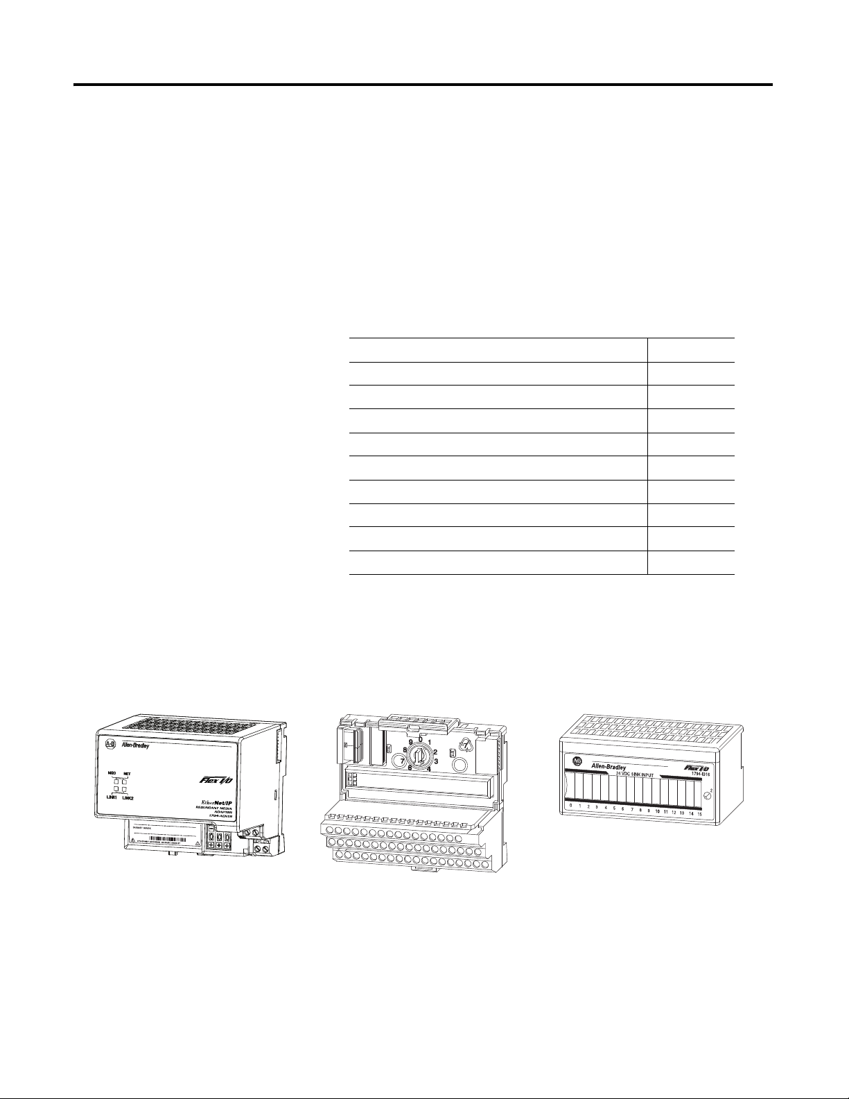
The FLEX I/O system is a small, modular I/O system for distributed
applications that performs all of the functions of rack-based I/O. The FLEX I/O
system contains the following components:
• Adapter – transfers read and write configuration data to and from the
I/O module
• Terminal base – contains a terminal strip to terminate wiring for two- or
three-wire devices
• I/O module – contains the bus interface and circuitry needed to perform
specific functions related to your application
1 Publication 1794-UM066A-EN-P - February 2012
Page 10

2 Overview of FLEX I/O and Your Redundant EtherNet/IP Adapter Module
The FLEX system consists of an adapter module, terminal base unit, DIN rail,
power supply, and adapter cabling components. You can use up to 8 terminal
bases per adapter module.
For detailed instructions on how to set up and install your module, refer to the
topic, Install Your FLEX I/O Adapter on page 7.
Adapter Features
Types of Adapters
The 1794-AENTR and 1794-AENTRXT adapter features include:
• use of EtherNet/IP messages encapsulated within standard TCP/UDP/IP
protocol
• common application layer with ControlNet and DeviceNet
• interfacing via Category 5 rated twisted pair cable
• half/full duplex 10 Mbit or 100 Mbit operation
• DIN rail mounting
• communication to and from other FLEX I/O modules on the same
DIN rail
• communication supported by RSLinx software
• IP address assigned via standard BootP/DHCP tools
• I/O configuration via RSLogix 5000 software
• no network scheduling required
• no routing tables required
The adapter refers to the following catalogs.
Catalog Voltage Module
Capacity
1794-AENTR 24V DC 8, max. Dual port EtherNet/IP adapter
1794-AENTRXT 24V DC 8, max. Dual port EtherNet/IP adapter with extended
Description
temperatures range
Hardware and Software Compatibility
Publication 1794-UM066A-EN-P - February 2012
The adapters and the applications described in this manual are compatible with
the following firmware versions and software releases. Contact Rockwell
Automation if you need software or firmware upgrades to use this equipment.
Hardware and Software Compatibility
Product Firmware Version/
Software Release
1794-AENTR/1794-AENTRXT adapter 1.xx or higher
Logix 557x Controller 20 or higher
RSLogix 5000 Software 20 or higher
RSLinx software 2.59 or higher
Page 11
Overview of FLEX I/O and Your Redundant EtherNet/IP Adapter Module 3
L
5
5
7
2
EtherNet/IP network
E
N
2
T
R
Other
network
devices
A
E
N
T
R
FLEX
I/O
E
N
2
T
R
ControlLogix
I/O
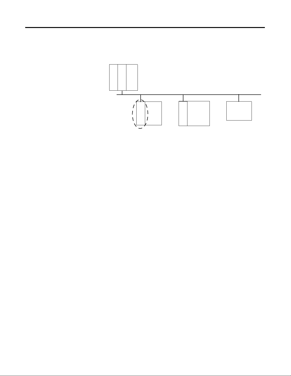
What the Adapter Does
Use of the Control and Information Protocol (CIP)
The 1794-AENTR and 1794-AENTRXT adapters perform two primary tasks:
• Control of real time I/O data (implicit messaging). The adapter serves as a
bridge between I/O modules and the network.
• Support of messaging data for configuration and programming
information(explicit messaging).
The 1794-AENTR and 1794-AENTRXT adapters use the Control and
Information Protocol (CIP). CIP is the application layer protocol specified for
EtherNet/IP, the Ethernet Industrial Protocol, as well as for ControlNet and
DeviceNet. It is a message-based protocol that implements a relative path to send
a message from the producing device in a system to the consuming devices.
The producing device contains the path information that steers the message
along the proper route to reach its consumers. Since the producing device holds
this information, other devices along the path simply pass this information; they
do not need to store it.
This has two significant benefits:
• You do not need to configure routing tables in the bridging modules,
which greatly simplifies maintenance and module replacement.
• You maintain full control over the route taken by each message, which
enables you to select alternative paths for the same end device.
Understanding the Producer/Consumer Model
The CIP producer/consumer networking model replaces the old
source/destination (master/slave) model. The producer/consumer model
reduces network traffic and increases speed of transmission. In traditional I/O
systems, controllers poll input modules to obtain their input status. In the CIP
system input modules are not polled by a controller. Instead, they produce
(multicast) their data either upon a change of state (COS) or periodically. The
frequency of update depends upon the options chosen during configuration and
where on the network the input module resides. The input module, therefore, is a
producer of input data and the controller is a consumer of the data.
Publication 1794-UM066A-EN-P - February 2012
Page 12

4 Overview of FLEX I/O and Your Redundant EtherNet/IP Adapter Module
The controller can also produce data for other controllers to consume. The
produced and consumed data is accessible by multiple controllers over the
EtherNet/IP network. This data exchange conforms to the producer/consumer
model.
Specifying the Requested Packet Interval (RPI)
Support of Rack Optimized and Direct Connections
The RPI is the update rate specified for a particular piece of data on the network.
The RPI can be specified for the adapter and include all of the I/O modules
communicating through it (using a rack optimized connection) or specified for a
particular module (using direct connection). When you add a module or an
adapter to the I/O configuration of a controller, you must enter the RPI as a
parameter. This value specifies how often to produce the data for that device. For
example, if you specify an RPI of 50 ms, it means that every 50ms the device
should send its data to the controller or the controller should send its data to the
device.
RPIs are only used for devices that produce data. For example, a ControlLogix
EtherNet/IP bridge module in the same chassis as the controller does not require
an RPI because it is not a data-producing member of the system; it is used only as
a bridge to remote racks.
The 1794-AENTR and 1794-AENTRXT adapters support both direct and rack
optimized connections. A direct connection is a real-time data transfer link
between the controller and the device that the configuration data references.
Direct connection messaging occurs at a cyclic rate specified by the RPI during
configuration. A rack optimized connection is a grouping of data from more than
one I/O module into a single block of data sent over a single connection at the
same data rate.
Publication 1794-UM066A-EN-P - February 2012
Rack optimized connections reduce the total number of connections needed to
transfer data when using many I/O modules in a system. The following example
illustrates the benefit of rack optimized connections.
Assume you have set up a system that contains 8 discrete I/O modules interfaced
to an adapter. If you use direct connections to transfer data to each of the these
I/O modules, you need 8 connections to transfer all of the data, one to each of
Page 13

Overview of FLEX I/O and Your Redundant EtherNet/IP Adapter Module 5
IMPORTANT
the 8 I/O modules. If you use a rack-optimized connection to transfer the data,
you only need a single connection – the connection to the adapter.
Refer to the EtherNet/IP Embedded Switch Technology Application Guide,
publication number ENET-AP005
Mixing Rack Optimized and Direct Connections
Although rack optimized connections offer an efficient way to use
resources, there are a few limitations on their use:
• You can only use rack optimized connections to send data to and
from discrete I/O modules. Analog I/O requires direct
connections.
• Rack optimized connections can contain I/O data and status
information only. Additional module information, such as
diagnostics, is not available through a rack-optimized connection.
• All data is sent at the same time at the RPI rate of the adapter.
, for more information on connections.
Chapter Summary
You can mix communication formats for different I/O modules communicating
through the same adapter. I/O modules set up to use rack optimization will
communicate at the rate of the requested packet interval (RPI) configured for the
1794-AENTR or 1794-AENTRXT adapter. I/O modules configured for direct
communication will communicate at their own set RPIs and ignore the
adapter RPI.
This chapter briefly described the FLEX I/O system, the FLEX I/O dual port
EtherNet/IP adapters, and the basic adapter features. Read the next chapter to
learn how to physically install the adapters and connect them to the EtherNet/IP
network.
Publication 1794-UM066A-EN-P - February 2012
Page 14

6 Overview of FLEX I/O and Your Redundant EtherNet/IP Adapter Module
Notes:
Publication 1794-UM066A-EN-P - February 2012
Page 15
Install Your FLEX I/O Adapter
1
9
8
7
5
6
3
2
45821
4
Chapter
2
Overview
Module Components
This chapter describes how to physically install the 1794-AENTR or
1794-AENTRXT adapter on the DIN rail and connect it to the EtherNet/IP
network. The following table lists where to find specific information.
Topic Page
Module Components 7
Mount Your Adapter on a DIN Rail 8
Mount on a Panel or Wall 9
Connect Wiring 11
Set the Network Address 12
Mounting Dimensions 13
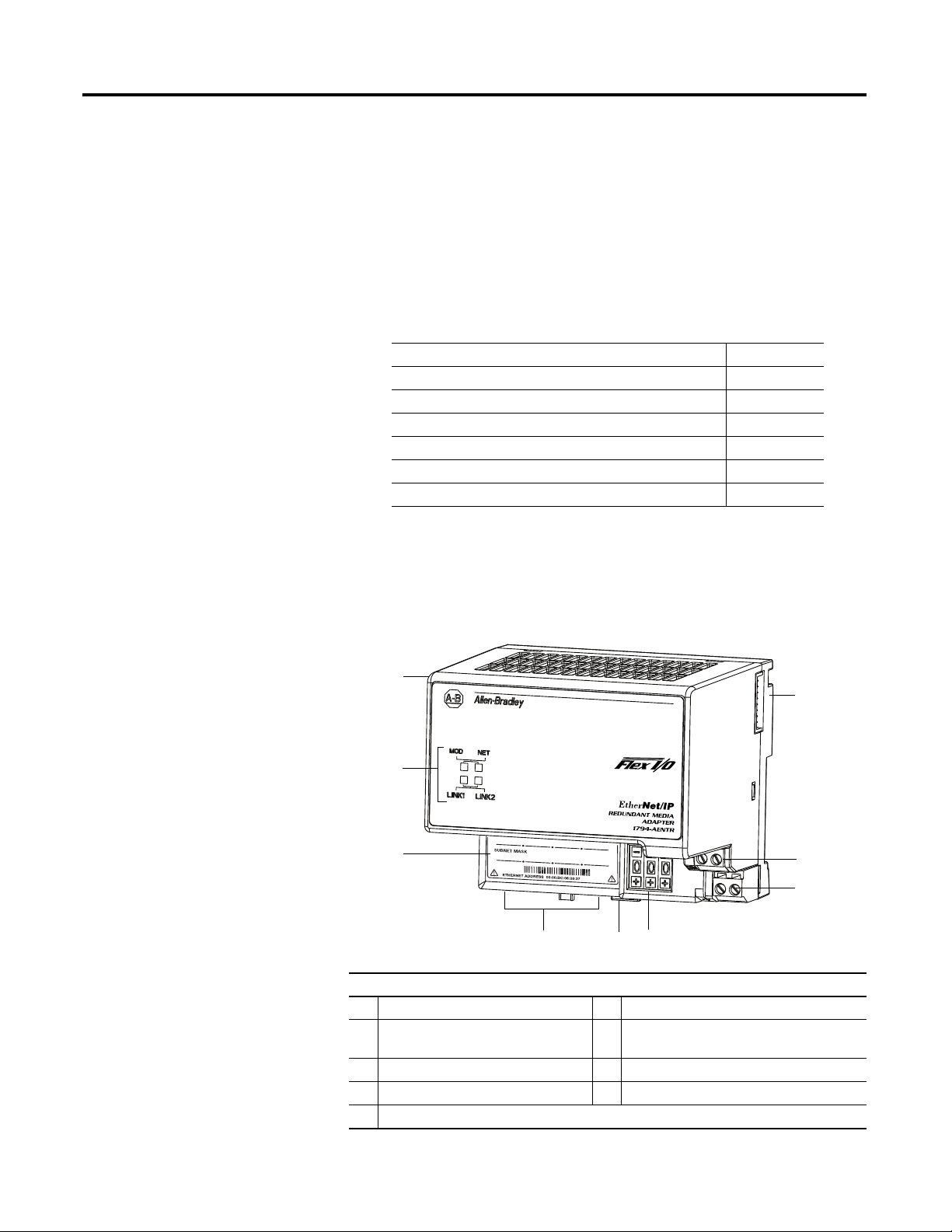
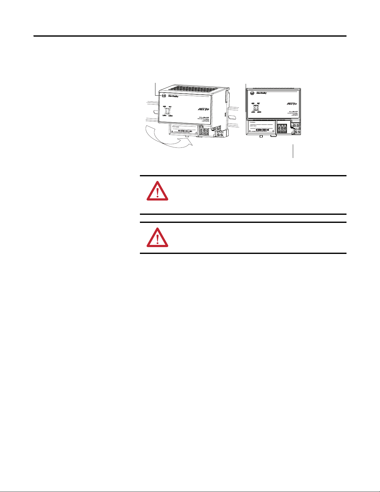
Use the following illustration to identify the external features of the FLEX I/O
EtherNet/IP adapter.
Dual Port EtherNet/IP Adapter – 1794-AENTR, 1794-AENTRXT
Component Identification
1 Dual Port EtherNet/IP adapter 6 Module locking tab
2 FlexBus connector 7 Network cable RJ45 connectors
3 24V common connections 8 MAC ID label
4 24V DC connections 9 Status indicators
5 IP address switches
(underside)
Page 16
8 Install Your FLEX I/O Adapter
45822
A B
C
Mount Your Adapter on a DIN Rail
Follow these steps to mount the adapter on a new system before installing any
I/O modules.
ATTENTION: During mounting of all devices, be sure that all
debris (for example, metal chips, wire strands) is kept from falling
into the module. Debris that falls into the module could cause
damage on power up.
ATTENTION: Do not remove or replace an Adapter Module while
power is applied. Interruption of the backplane can result in
unintentional operation or machine motion.
1. Position the adapter module (A) on an IEC standard (35 x 7.5 x 1 mm)
top-hat DIN rail (B) at a slight angle (DIN rail: Allen-Bradley part
number 199-DR1; 46277-3; EN50022).
2. Hook the lip on the rear of the adapter onto the top of the DIN rail, and
pivot the adapter module onto the rail.
3. Press the adapter module down onto the DIN rail until flush. Locking tab
(C) snaps the adapter into position and locks it onto the DIN rail.
4. If the adapter module does not lock in place, use a screwdriver or similar
device to move the locking tab down while pressing the adapter module
flush onto the DIN rail, and release the locking tab to lock the adapter
module in place.
If necessary, push up on the locking tab to lock.
5. Connect the adapter wiring as shown in the Connect Wiring diagram.
Publication 1794-UM066A-EN-P - February 2012
Page 17
Install Your FLEX I/O Adapter 9
Mount on a Panel or Wall
If mounting this adapter to a panel or wall, refer to publication 1794-TD013,
Panel Mounting Kit, Cat. No. 1794-NM1.
ATTENTION: If you insert or remove the module while backplane
power is on, an electrical arc can occur. This could cause an
explosion in hazardous location installations. Be sure that power is
removed or the area is nonhazardous before proceeding.
WARNING: When used in a Class I, Division 2, hazardous
location, this equipment must be mounted in a suitable enclosure
with proper wiring method that complies with the governing
electrical codes.
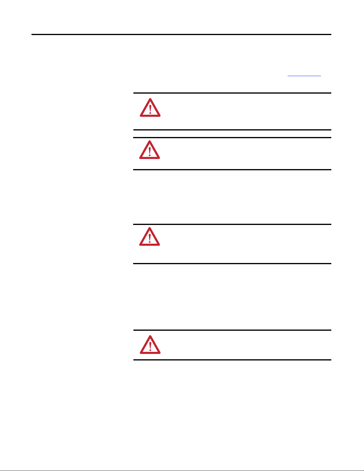
Mount or Replace the Adapter on an Existing System
1. Disconnect any wiring jumpered to the adjacent terminal base.
2. Remove the Ethernet connectors from the bottom of the adapter.
WARNING: If you connect or disconnect the communication cable
with power applied to the adapter or any device on the network, an
electrical arc can occur. This could cause an explosion in hazardous
location installations. Be sure that power is removed or the area is
nonhazardous before proceeding.
3. Disconnect any user power wiring connections to the adapter.
4. Open the module latching mechanism and remove the module from the
base unit to which the adapter will be attached.
5. Push the FlexBus connector toward the right side of the terminal base to
unplug the backplane connection.
ATTENTION: Make certain the FlexBus connector is completely
clear of the adapter. The slide must be completely to the right and
the raised spot on the slide visible.
6. Release the locking tab and remove the adapter module.
Before installing the new adapter, notice the notch on the right rear of the
adapter. This notch accepts the hook on the terminal base unit. The notch
is open at the bottom. The hook and adjacent connection point keep the
Publication 1794-UM066A-EN-P - February 2012
Page 18
10 Install Your FLEX I/O Adapter
terminal base and the adapter tight together, reducing the possibility of a
break in communication over the backplane.
7. Complete the adapter mounting as shown below.
Push down and in at the same time to lock the adapter to the DIN rail.
If the adapter does not lock in place, use a screwdriver or similar device to
move the locking tab down while pressing the adapter flush onto the DIN
rail, and release the locking tab to lock the adapter module in place. If
necessary, push up on the locking tab to lock.
When the adapter is locked onto the DIN rail, gently push the FlexBus
connector into the adapter to complete the backplane.
8. Reinstall the module in the adjacent terminal base unit.
Publication 1794-UM066A-EN-P - February 2012
Page 19
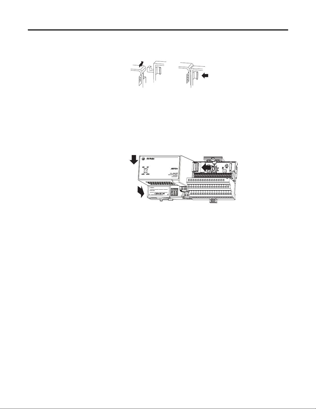
Connect Wiring
A
FE
CD
45823
B
A B
Install Your FLEX I/O Adapter 11
WARNING: If you connect or disconnect wiring while the
field-side power is on, an electrical arc can occur. This could cause
an explosion in hazardous location installations. Be sure that
power is removed or the area is nonhazardous before proceeding.
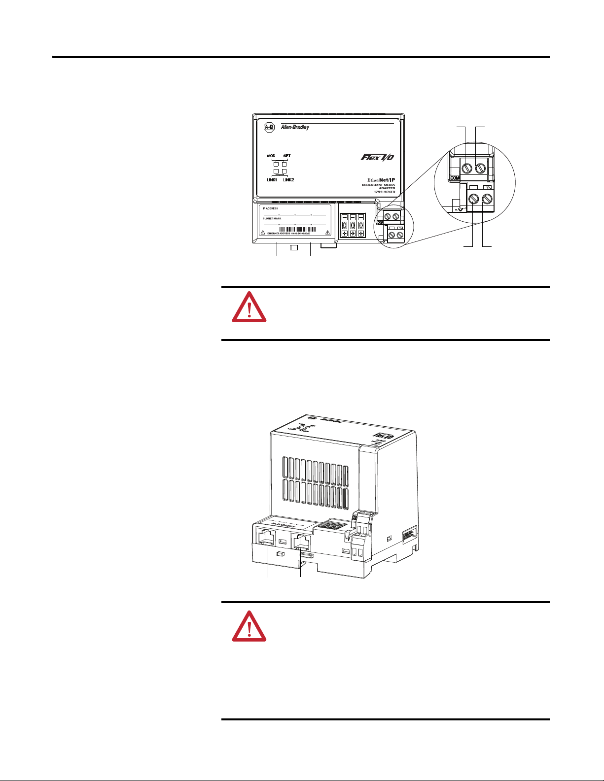
1. Connect an Ethernet network cable to the RJ45 connector (A).
2. Connect the redundant Ethernet network cable to the RJ45
connector (B).
ATTENTION: When connecting wiring, torque terminal screws C,
D, E and F to 0.8 Nm (7 lb-in.).
ATTENTION: If multiple power sources are used, do not exceed
the specified isolation voltage.
ATTENTION: Power wiring must be less than 10 m (32.8 ft.) in
length.
ATTENTION: Do not wire more than two conductors on any single
terminal.
Publication 1794-UM066A-EN-P - February 2012
Page 20
12 Install Your FLEX I/O Adapter
45824
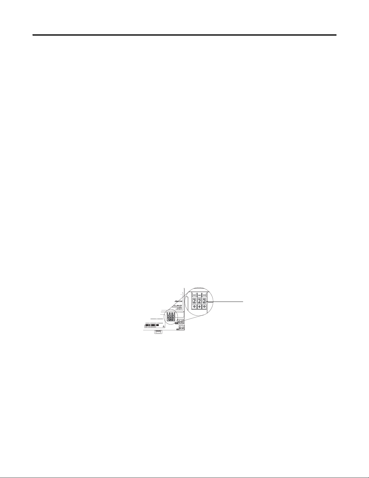
Press the + or - buttons to
change the numbers
3. Connect 24V DC common to the left side of the upper connector,
terminal F.
4. Connect +24V DC input power to the left side of the lower
connector, terminal C.
5. Use connections D and E to pass +24V DC common (E) and
24V DC power (D) to the next module in the series (if required).
Set the Network Address
The adapter ships with the thumbwheel switches set to 999 and DHCP enabled.
You can set the network Internet Protocol (IP) address in these ways:
• Use the thumbwheel switches on the module.
• Use a Dynamic Host Configuration Protocol (DHCP) server, such as
Rockwell Automation DHCP.
• Retrieve the IP address (if previously set) from nonvolatile memory.
The adapter reads the thumbwheel switches first to determine if the switches are
set to a valid number. You set the node address by using the three-position
thumbwheel switch. Press the + or - buttons to change the number. Valid settings
are 001…254.
When the switches are set to a valid number, the adapter IP address is
192.168.1.xxx (where xxx represents the number set on the switches). The
adapter subnet mask is 255.255.255.0 and the gateway address is set to 0.0.0.0.
The adapter does not have a host name assigned, or use any Domain Name
System when using the thumbwheel settings.
If you set the switches to an invalid number (such as 000, or a value greater than
254), the adapter checks to see if you enabled DHCP.
Publication 1794-UM066A-EN-P - February 2012
Page 21
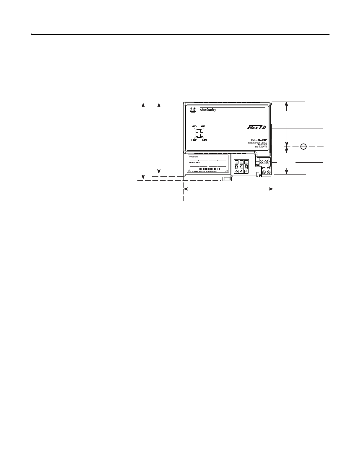
Mounting Dimensions
45826
1794-AENTR shown
Millimeters
(Inches)
80.4
(3.16)
87.4
(3.44)
94
(3.70)
1794-AENTR, 1794-AENTRXT
87.4 H x 94W x 92D
(344H x 3.7W x 3.6D)
50
(1.96)
30.4
(1.19)
The module has the following mounting dimensions.
Install Your FLEX I/O Adapter 13
Publication 1794-UM066A-EN-P - February 2012
Page 22

14 Install Your FLEX I/O Adapter
Notes:
Publication 1794-UM066A-EN-P - February 2012
Page 23

Configure the Adapter for Your
IMPORTANT
EtherNet/IP Network
Chapter
3
Overview
Configuration Requirements
This chapter describes how to configure the 1794-AENTR or 1794-AENTRXT
adapter module for the ControlLogix system.
Topic Page
Configuration Requirements
IP Address
Gateway Address
Subnet Mask
Use the Rockwell BootP/DHCP Utility
Configure Your Adapter using DHCP Software
Before you can use your 1794-AENTR or 1794-AENTRXT adapter, you must
configure its IP address, and optionally, its subnet mask and gateway address. You
can use the Rockwell BootP/DHCP utility to perform the configuration. You
can also use generic BootP software or, within some limitations, a DHCP server.
When using the BootP protocol, you must enter the Ethernet
hardware address of your adapter. Rockwell assigns each
1794-AENTR or 1794-AENTRXT adapter a unique 48-bit hardware
address at the factory. The address is printed on a label on the front
of your 1794-AENTR or 1794-AENTRXT adapter. It consists of six
hexadecimal digits separated by colons. This address is fixed by the
hardware and cannot be changed.
If you change or replace the 1794-AENTR or 1794-AENTRXT adapter,
you must enter the new Ethernet hardware address of the adapter
when you configure the new adapter.
15
15
16
17
18
21
IP Address
The IP address identifies each node on the IP network (or system of connected
networks). Each TCP/IP node on a network (including the 1794-AENTR or
1794-AENTRXT adapter) must have a unique IP address.
15 Publication 1794-UM066A-EN-P - February 2012
Page 24

16 Configure the Adapter for Your EtherNet/IP Network
Class A
Class B
Class C
Net ID
Net ID
Net ID
Host ID
Host ID
Host ID
0
0
0
1 0
1 1 0
8
9
16
24
17
31
31
31
25
0
EXAMPLE
TIP
The IP address is 32 bits long and has a Net ID part and a Host ID part.
Networks are classified A, B, C, (or other). The class of the network determines
how an IP address is formatted.
You can distinguish the class of the IP address from the first integer in its
dotted-decimal IP address as follows:
Range of first integer Class Range of first integer Class
0…127 A 192…223 C
128…191 B 224…255 other
Each node on the same physical network must have an IP address of the same
class and must have the same Net ID. Each node on the same network must have
a different Host ID thus giving it a unique IP address.
IP addresses are written as four decimal integers (0-255) separated by periods
where each integer gives the value of one byte of the IP address.
For example, the 32-bit IP address:
10000000 00000001 00000000 00000001 is written as
128.1.0.1.
Contact your network administrator or the Network Information
Center for a unique fixed IP address to assign to your module.
Gateway Address
The Gateway Address is the default address of a network. It provides a single
domain name and point of entry to the site. Gateways connect individual physical
networks into a system of networks. When a node needs to communicate with a
node on another network, a gateway transfers the data between the two
Publication 1794-UM066A-EN-P - February 2012
Page 25
Configure the Adapter for Your EtherNet/IP Network 17
EXAMPLE
Network 1
Network 2
128.2.0.3
128.1.0.2
128.1.0.1
128.2.0.1
128.2.0.2
A
B
C
G
11111111 11111111 11000000 00000001 = 255.255.192.0
These two bits of the host ID used to
extend the net ID
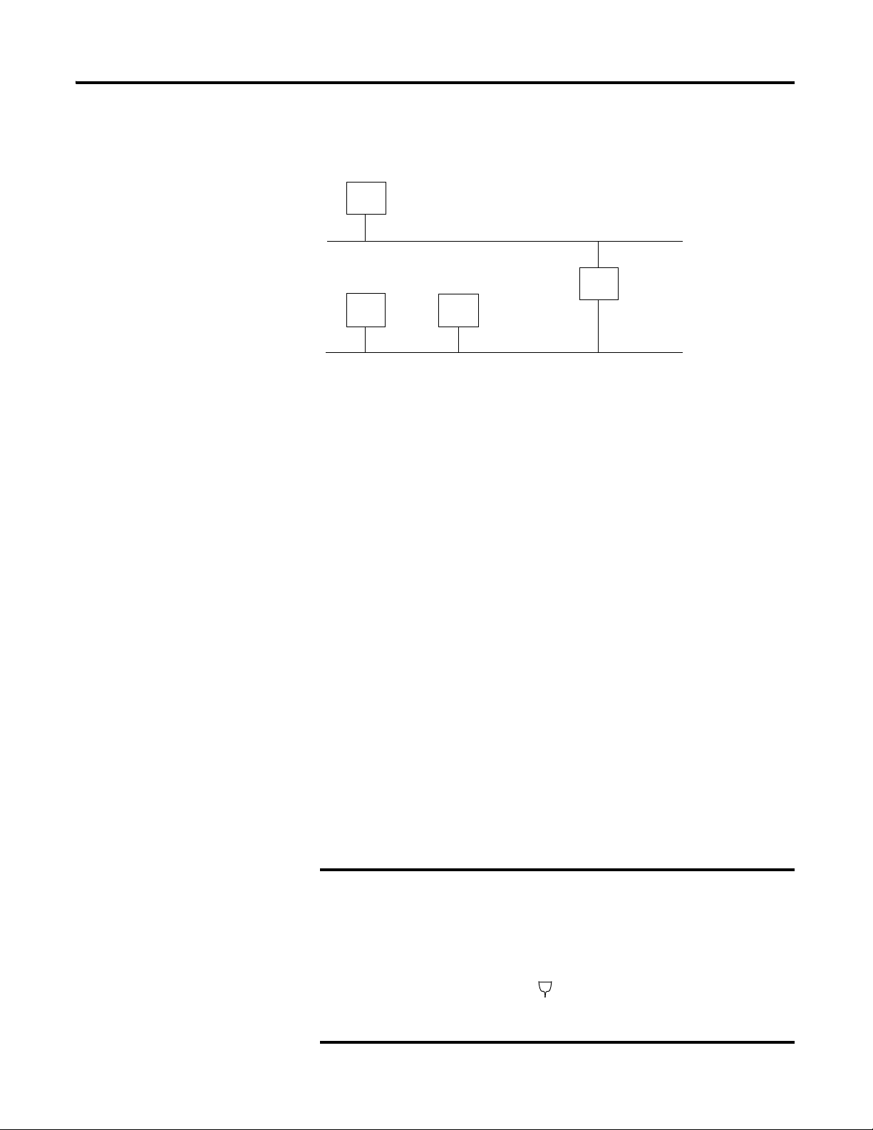
networks. The following figure shows gateway G connecting Network 1 with
Network 2.
When host B with IP address 128.2.0.1 communicates with host C, it knows
from C’s IP address that C is on the same network. In an Ethernet environment,
B then resolves C’s IP address into a hardware address (MAC address) and
communicates with C directly.
When host B communicates with host A, it knows from A’s IP address that A is
on another network (the net IDs are different). In order to send data to A, B must
have the IP address of the gateway connecting the two networks. In this example,
the gateway’s IP address on Network 2 is 128.2.0.3.
The gateway has two IP addresses (128.1.0.2 and 128.2.0.3). The first must be
used by hosts on Network 1 and the second must be used by hosts on Network 2.
To be usable, a host’s gateway must be addressed using a net ID matching its own.
Subnet Mask
The subnet mask is used for splitting IP networks into a series of subgroups, or
subnets. The mask is a binary pattern that is matched up with the IP address to
turn part of the Host ID address field into a field for subnets.
Take Network 2 (a Class B network) in the previous example and add another
network. Selecting the following subnet mask would add two additional net ID
bits, allowing for four logical networks:
Take Network 2 (a Class B network) in the previous example
and add another network. Selecting the following subnet mask
would add two additional net ID bits, allowing for four logical
networks:
Publication 1794-UM066A-EN-P - February 2012
Page 26

18 Configure the Adapter for Your EtherNet/IP Network
128.2.64.1
Network 1
Network 2.1
Network 2.2
128.1.0.1
128.1.0.2
128.2.128.3
A
B
C
G
D
128.2.128.1
128.2.128.2
E
G2
128.2.64.3
Two bits of the Class B host ID have been used to extend the net ID. Each unique
combination of bits in the part of the Host ID where subnet mask bits are 1
specifies a different logical network.
The new configuration is:
Use the Rockwell BootP/DHCP Utility
A second network with Hosts D and E was added. Gateway G2 connects
Network 2.1 with Network 2.2.
Hosts D and E use Gateway G2 to communicate with hosts not on Network 2.2.
Hosts B and C use Gateway G to communicate with hosts not on Network 2.1.
When B is communicating with D, G (the configured gateway for B) routes the
data from B to D through G2.
The Rockwell BootP/DHCP utility is a stand alone program that incorporates
the functionality of standard BootP/DHCP software with a user-friendly
graphical interface. It is located in the Utils directory on the RSLogix 5000
installation CD. The module must have DHCP enabled (factory default and the
network address switches set to an illegal value) to use the utility.
To configure your module using the BootP/DHCP utility, perform the following
steps:
1. Run the BootP/DHCP software.
Publication 1794-UM066A-EN-P - February 2012
Page 27
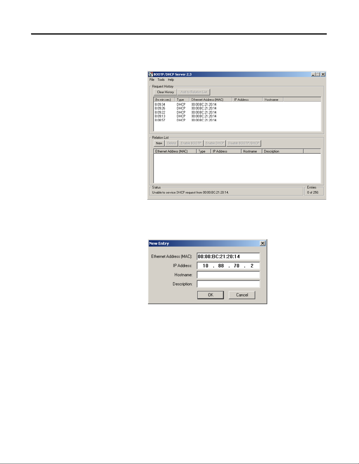
Configure the Adapter for Your EtherNet/IP Network 19
The BOOTP/DHCP Request History dialog appears showing the
hardware addresses of devices issuing BootP/DHCP requests.
2. Double-click the hardware address of the device you want to configure.
The New Entry dialog appears showing the device’s Ethernet
Address (MAC).
3. Enter the IP Address you want to assign to the device and click OK.
Publication 1794-UM066A-EN-P - February 2012
Page 28

20 Configure the Adapter for Your EtherNet/IP Network
TIP
The device is added to the Relation List, displaying the Ethernet Address
(MAC) and corresponding IP Address, Hostname and Description (if
applicable).
When the IP address assignment is made, the address displays in the IP
Address column in the Request History section.
4. To assign this configuration to the device, highlight the device in the
Relation List panel and click Disable BOOTP/DHCP. When power is
cycled to the device, it uses the configuration you assigned and not does
not issue a DHCP request.
To enable DHCP for a device that has had DHCP disabled, highlight the
device in the Relation List and click Enable DHCP. You must have an
entry for the device in the Relation List panel to re-enable DHCP.
Publication 1794-UM066A-EN-P - February 2012
Page 29

Configure the Adapter for Your EtherNet/IP Network 21
Save the Relation List
You can save the Relation List to use later. To save the Relation List do the
following:
1. Select Save As... from the File menu.
Configure Your Adapter using DHCP Software
The Save As dialog box appears.
2. Select the folder you want to save the list to.
3. Enter a file name for the Relation List (for example, control system
configuration) and click Save.
If you want to see your saved file names in the Open dialog box, save your
files using the default file type (*.bpc).
DHCP (Dynamic Host Configuration Protocol) software automatically assigns
IP addresses to client stations logging onto a TCP/IP network. DHCP is based
on BootP and maintains some backward compatibility. The main difference is
that BootP was designed for manual configuration, while DHCP allows for
Publication 1794-UM066A-EN-P - February 2012
Page 30

22 Configure the Adapter for Your EtherNet/IP Network
dynamic allocation of network addresses and configurations to newly attached
devices.
Be cautious about using DHCP software to configure your adapter. A BootP
client, such as the 1794-AENTR or 1794-AENTRXT adapter, can boot from a
DHCP server only if the DHCP server is specifically written to also handle
BootP queries. This is specific to the DHCP software package you use. Check
with your system administrator to see if your DHCP package supports BootP
commands and manual IP allocation.
ATTENTION: The 1794-AENTR or 1794-AENTRXT adapter must be
assigned a fixed network address. The IP address of this adapter must
not be dynamically provided.
Failure to observe this precaution may result in unintended machine
motion or loss of process control.
Chapter Summary
This chapter described how to configure the module to communicate on your
EtherNet/IP network by providing an IP address, gateway address, and Subnet
mask. Read the next chapter to learn how to set up your adapter for a rack
optimized system.
Publication 1794-UM066A-EN-P - February 2012
Page 31

Rack Optimized Discrete I/O
Chapter
4
Overview
In this example a ControlLogix processor communicates with FLEX I/O via the
1794-AENTR adapter using a rack optimized connection. The processor reads
data from all digital input modules and sends data to all digital output modules
configured in a rack connection simultaneously.
The following table lists where to find specific information within this chapter.
Topic Page
Set Up the Hardware 23
Create the Example Application 24
Configure the I/O 26
Add the Local EtherNet/IP Bridge to the I/O Configuration 26
Add the FLEX I/O Adapter to the I/O Configuration 27
Add the FLEX I/O Modules to the I/O Configuration 29
Add the Digital Input Module 30
Add the Digital Output Module 31
Edit the Controller Tags 33
Create the Ladder Program 34
Download the Program to the Controller 34
Test the Example Application 35
Set Up the Hardware
23 Publication 1794-UM066A-EN-P - February 2012
In this example, a ControlLogix chassis contains the Logix5572 controller in
slot 0 and a 1756-EN2TR bridge module in slot 1. The adapter is mounted on a
DIN rail with a 1794-IB16 digital input module and 1794-OB16 digital output
module. You also need a power supply (not shown) for the FLEX I/O.
Page 32
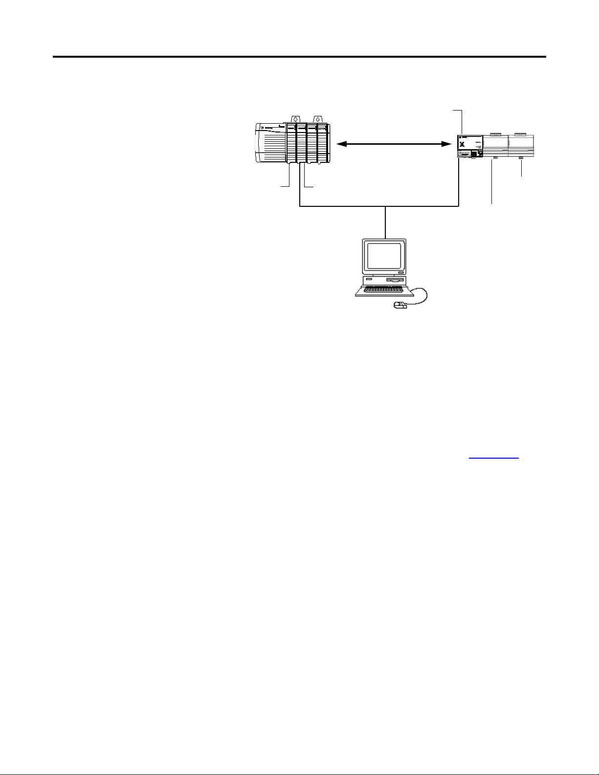
24 Rack Optimized Discrete I/O
Local
chassis
FLEX I/O
Logix5572c
ontroller
1794-OB16
digital output
1794-IB16
digital input
1756-EN2TR
130.130.130.2
1794-AENTR
130.130.130.3
Data
Programming
terminal
130.130.130.1
SLOT 1 2
SLOT 1 2
Create the Example Application
To work along with this example set up your system as shown above.
Perform the following steps to create the example application:
• Note that in the example application, the Logix5572 controller and
1756-EN2TR module are assumed to be in the slots shown above.
• Verify the IP addresses for your programming terminal, 1756-EN2TR
module, and 1794-AENTR adapter.
• Verify the position (slot) of the I/O modules on the DIN rail.
• Verify that all wiring and cabling is properly connected.
• Make sure your communication driver (for example, AB_ETH-1 or
AB-ETHIP-1) is configured in RSLinx as described in Appendix C
.
Publication 1794-UM066A-EN-P - February 2012
Page 33
Rack Optimized Discrete I/O 25
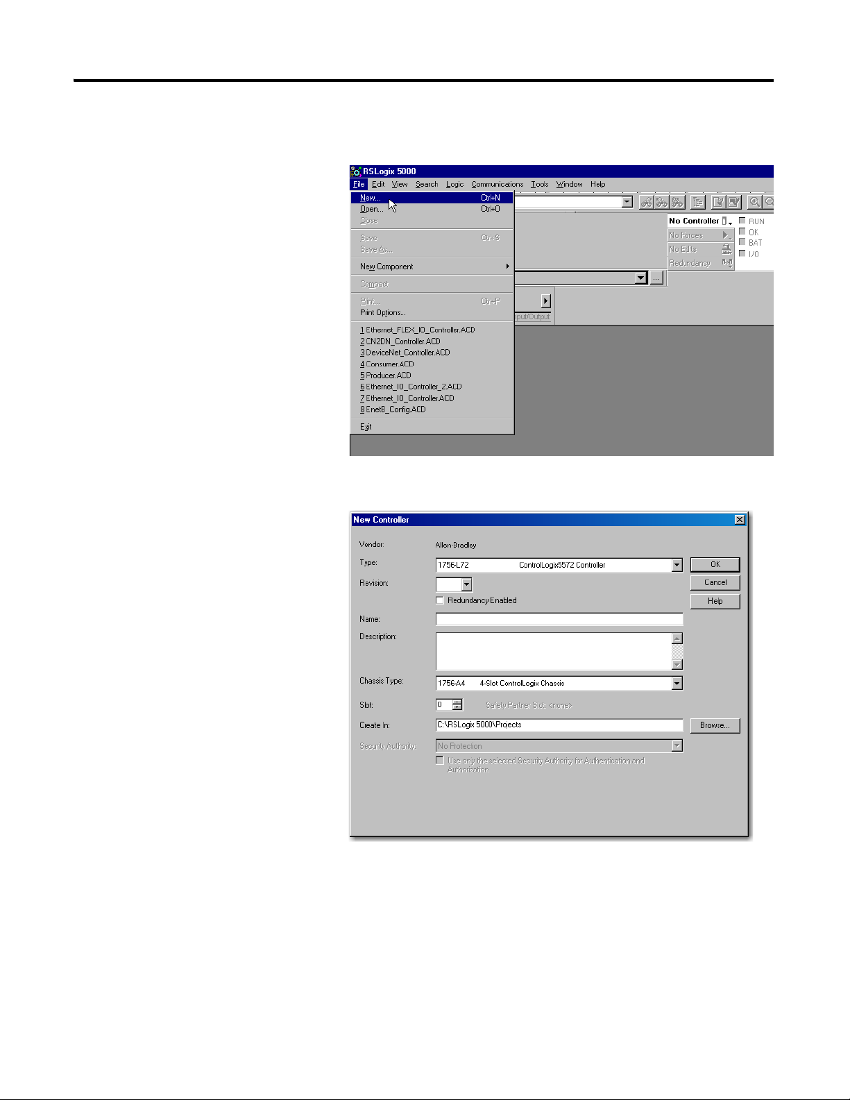
1. Start the RSLogix 5000 Enterprise Series software.
The RSLogix 5000 main dialog opens.
2. From the File menu, select New.
The New Controller dialog opens.
3. Enter an appropriate Name for the Controller, for example:
FLEX_IO_Controller.
4. Select the correct Chassis Type and Slot number of the Logix5572
controller, and the folder where you want to save the RSLogix 5000 file
(Create In). The Description is optional.
5. Click OK.
Publication 1794-UM066A-EN-P - February 2012
Page 34
26 Rack Optimized Discrete I/O
IMPORTANT
Configure the I/O
Setting up a sample I/O Configuration project involves the following:
• Adding the local 1756-EN2TR module to the I/O configuration.
• Adding the 1794-AENTR adapter as a child of the
1756-EN2TR module.
• Adding the I/O modules as children of the adapter.
Click the Help button on the configuration dialogs shown in this
section if you need assistance in selecting and setting the
parameters.
Add the Local EtherNet/IP Bridge to the I/O Configuration
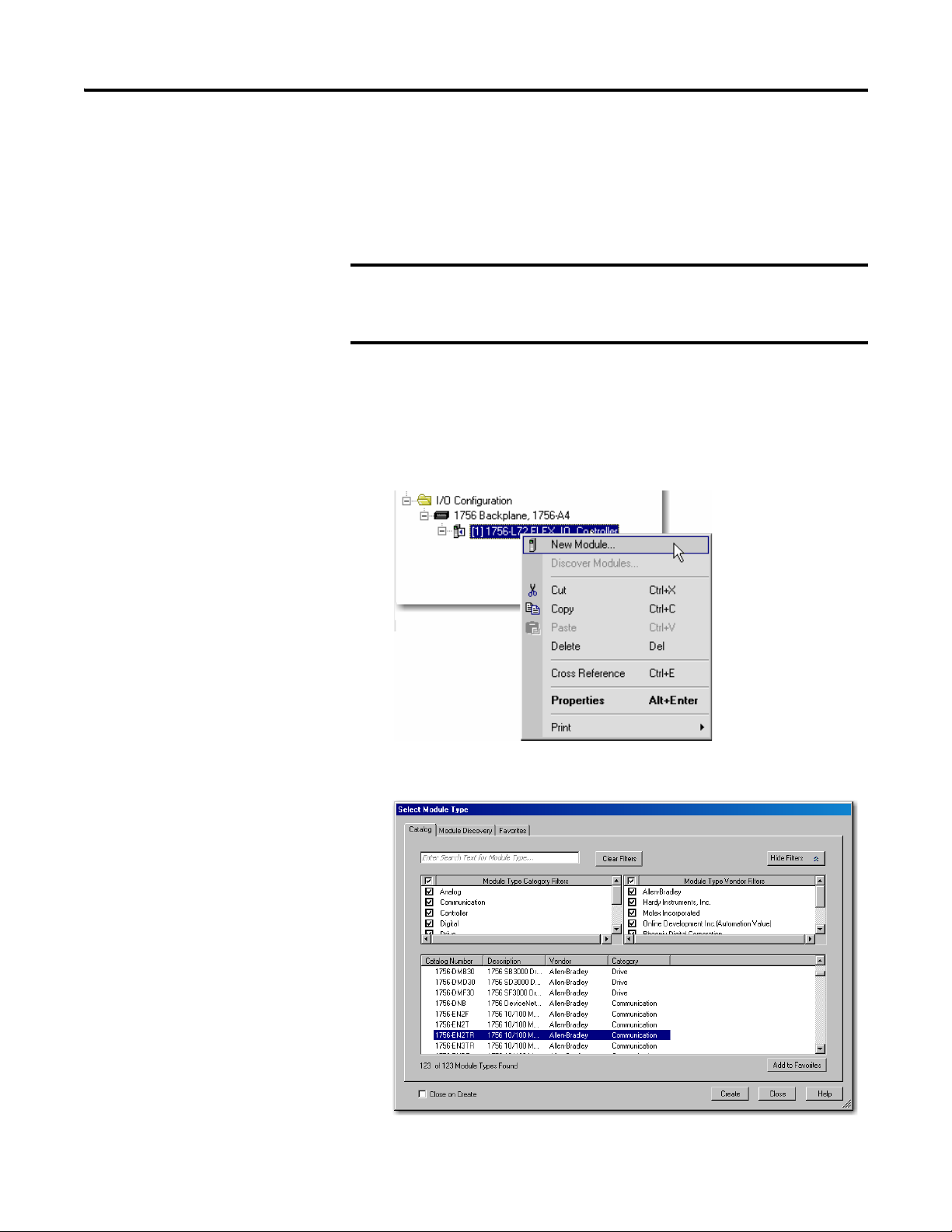
1. Right-click the I/O Configuration folder in the project window, and then
select New Module.
2. The Select Module Type window opens.
Publication 1794-UM066A-EN-P - February 2012
Page 35
Rack Optimized Discrete I/O 27
3. Select the 1756-EN2TR EtherNet/IP Bridge, and then click Create.
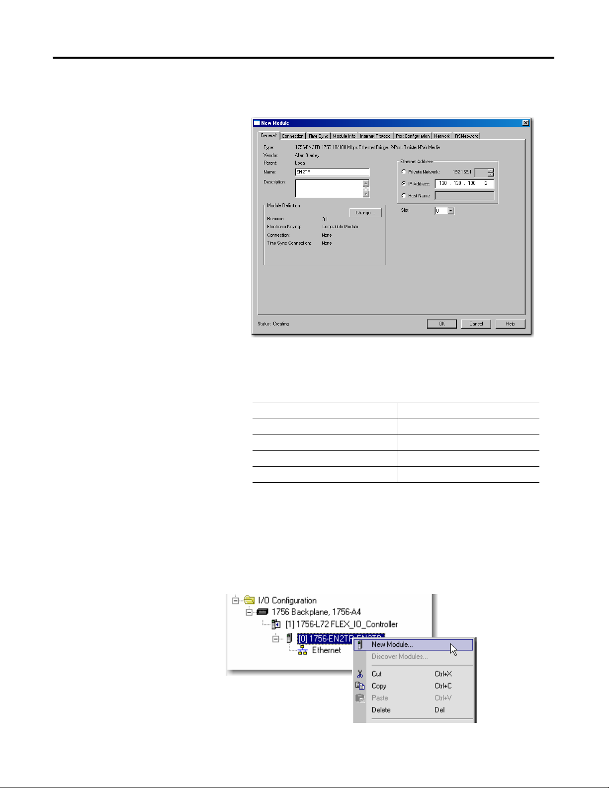
The New Module dialog opens.
4. Configure your 1756-EN2TR EtherNet/IP Bridge module through the
different tabs available.
Enter values for Name, IP Address, Slot, Electronic Keying, and Revision,
as follows:
Name EN2TR
IP Address 130.130.130.2
Slot 0
Electronic Keying Compatible Module
Revision 3.1
5. Click OK to accept the configuration.
Add the FLEX I/O Adapter to the I/O Configuration
Next, you must add the 1794-AENTR adapter as a child of the local
1756-EN2TR module.
Publication 1794-UM066A-EN-P - February 2012
Page 36
28 Rack Optimized Discrete I/O
1. In the Project dialog, right-click the local 1756-EN2TR module under the
I/O Configuration folder, and then select New Module.
The Select Module Type dialog opens.
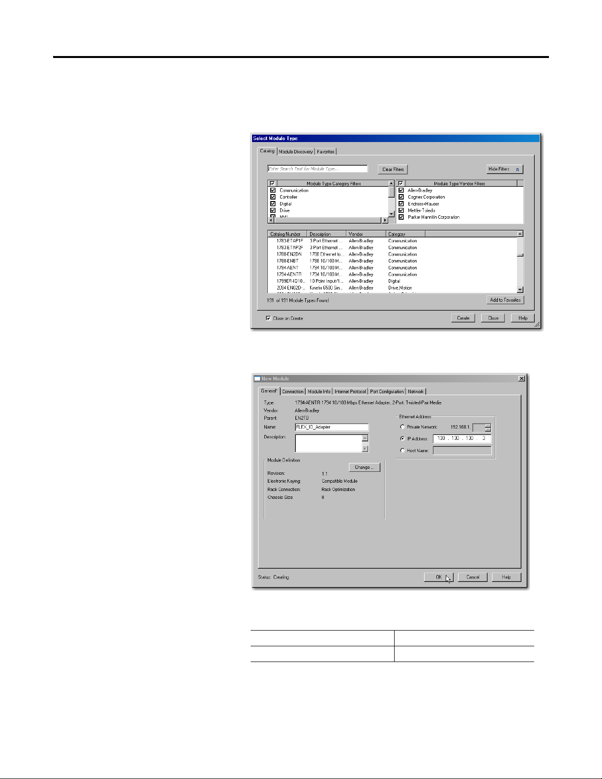
2. Select the 1794-AENTR Ethernet adapter from the list and click Create.
The Module Properties dialog opens.
3. Specify the following parameters in the General tab of the New Module
dialog:
Publication 1794-UM066A-EN-P - February 2012
Name FLEX_IO_Adapter
IP Address 130.130.130.3
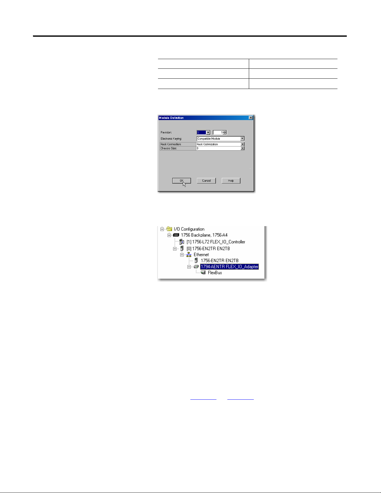
4. Verify that the Module Definition values are as follows:
Page 37
Rack Optimized Discrete I/O 29
TIP
Comm Format Rack Optimization
Chassis Size 8 (default)
Electronic Keying Compatible Module
5. If you need to change the values, click Change...
The Module Definition dialog opens.
6. Click OK to accept the configuration.
The 1794-AENTR adapter appears indented under the local 1794-ENBT
in the I/O Configuration folder.
Add the FLEX I/O Modules to the I/O Configuration
You must now add the FLEX I/O modules to the I/O Configuration List under
the 1794-AENTR adapter.
In this example, you add a 1794-IB16 digital input module and a 1794-OB16
digital output module with standard configurations. Use these steps as a guide
when you are configuring different I/O modules for your system.
This example application uses I/O module default configurations.
For more information, refer to the I/O module publications
1794-IN093
Publication 1794-UM066A-EN-P - February 2012
and 1794-IN094.
Page 38
30 Rack Optimized Discrete I/O
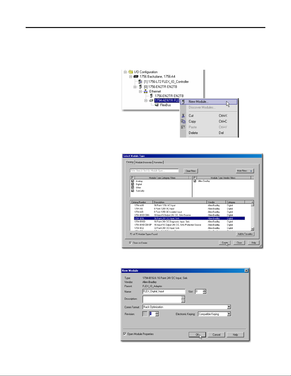
Add the Digital Input Module
1. Under the I/O Configuration folder, right-click the remote
1794-AENTR adapter, and then select New Module.
The Select Module Type window opens.
Publication 1794-UM066A-EN-P - February 2012
2. Select the 1794-IB16 module from the list, and then click Create.
The New Module dialog opens.
Page 39
Rack Optimized Discrete I/O 31
3. Enter the following parameters:
Name FLEX_Digital_Input
Slot 0
Comm Format Rack Optimization
Electronic Keying Compatible Module
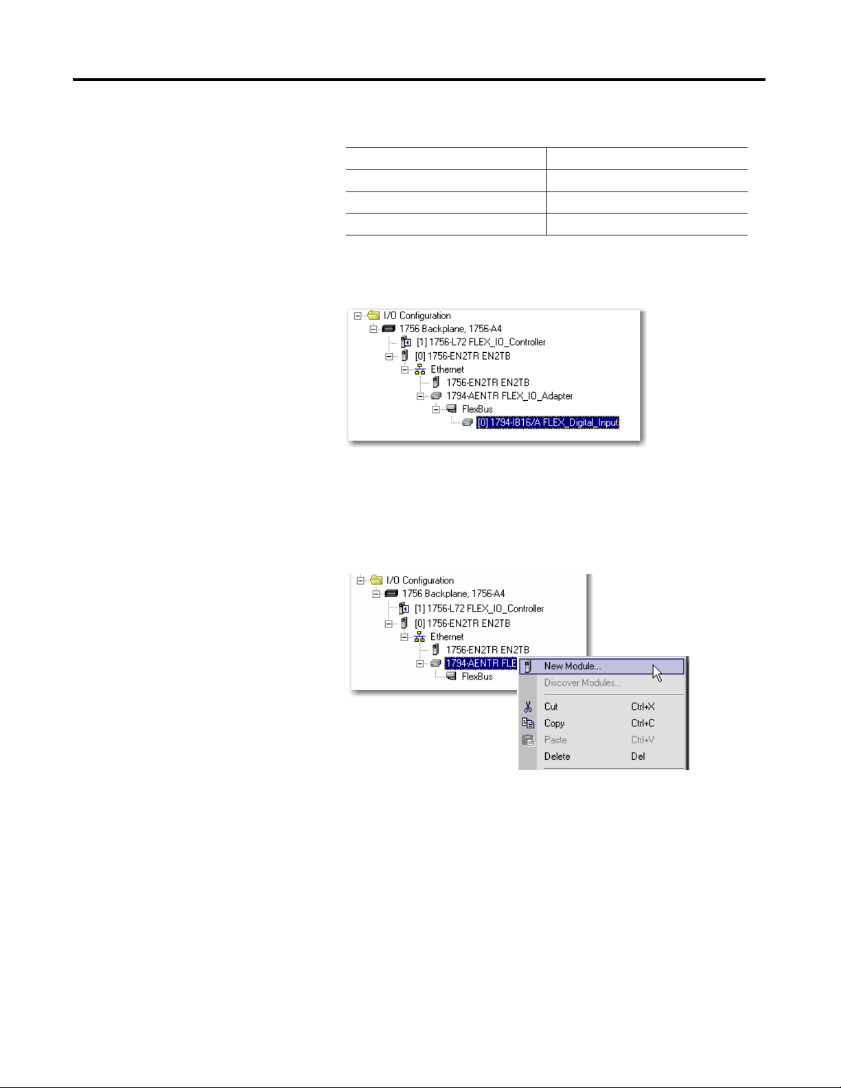
4. Click OK to save the configuration.
The digital input module appears in the I/O configuration indented under
the 1794-AENTR adapter.
Add the Digital Output Module
1. Under the I/O Configuration folder, right-click the remote
1794-AENTR adapter, and then select New Module.
Publication 1794-UM066A-EN-P - February 2012
Page 40
32 Rack Optimized Discrete I/O
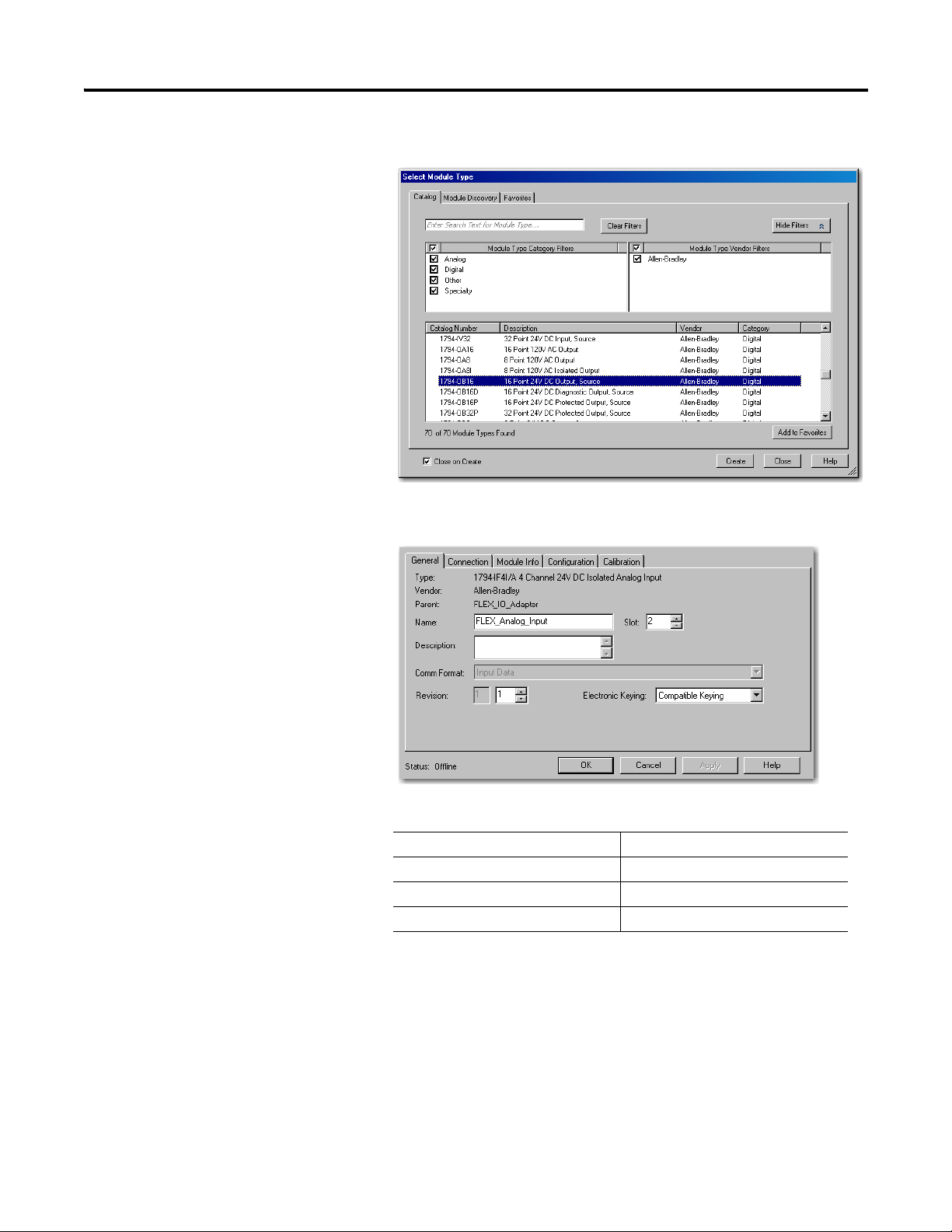
The Select Module Type window opens.
2. Select the 1794-OB16 module from the list, and then click Create.
The New Module dialog opens.
Publication 1794-UM066A-EN-P - February 2012
3. Enter the following parameters:
Name FLEX_Digital_Output
Slot 1
Comm Format Rack Optimization
Electronic Keying Compatible Module
Page 41
Rack Optimized Discrete I/O 33
Enter the new tag here
Tags created
by the system
4. Click OK to save the configuration.
The digital input module appears in the I/O configuration indented under
the 1794-AENTR adapter.
Edit the Controller Tags
When you add modules to the I/O configuration the system creates tags for those
modules to use in the application program. For the example application you need
to add one more Controller Tag.
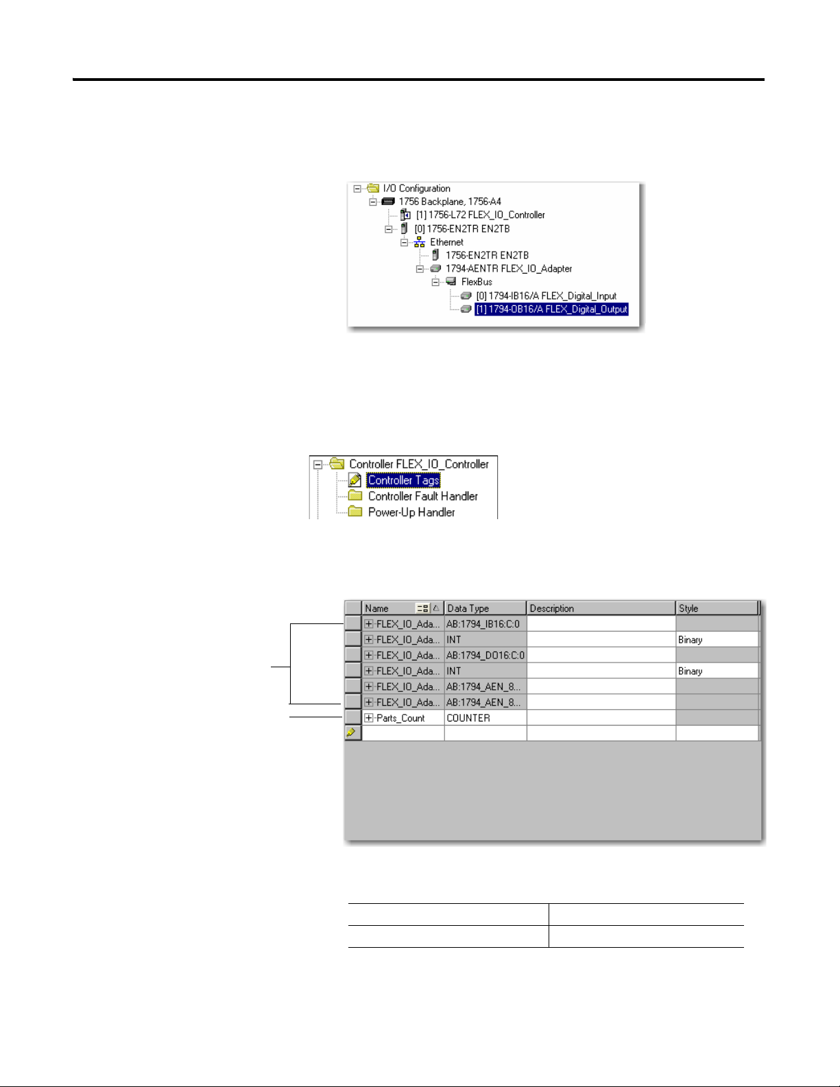
1. Double-click the Controller Tags folder in the project window.
The Controller Tags window opens. You see the tags created for the
1794-AENTR and digital I/O modules.
2. Make sure you select the Edit Tags tab at the bottom of the Controller
Tags window, and then create the following tag:
Tag Type
Parts_Count Counter
3. Close the Controller Tags window.
Publication 1794-UM066A-EN-P - February 2012
Page 42

34 Rack Optimized Discrete I/O
Create the Ladder Program
Next, create the example ladder program to test the I/O.
1. Double-click Main Routine under the Main Program folder, and then
enter the following ladder program, using the tag previously created.
Publication 1794-UM066A-EN-P - February 2012
2. Save the program.
Download the Program to the Controller
To download the program to the controller do the following:
Page 43

Rack Optimized Discrete I/O 35
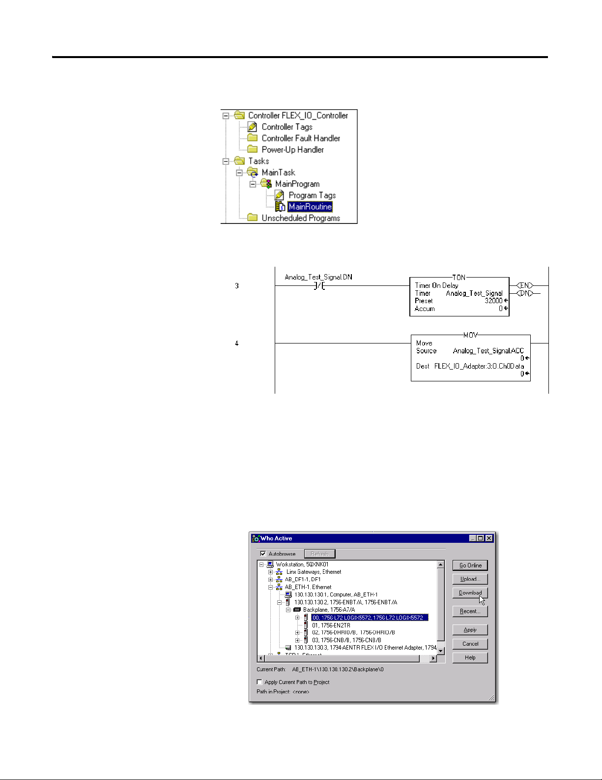
1. Click on the Communications menu and select Who Active.
The Who Active window opens .
2. Select your Ethernet driver (for example, AB_ETH-1) and expand the tree
through the backplane of the local ControlLogix chassis.
Test the Example Application
3. Highlight the Logix5572 controller and click Download.
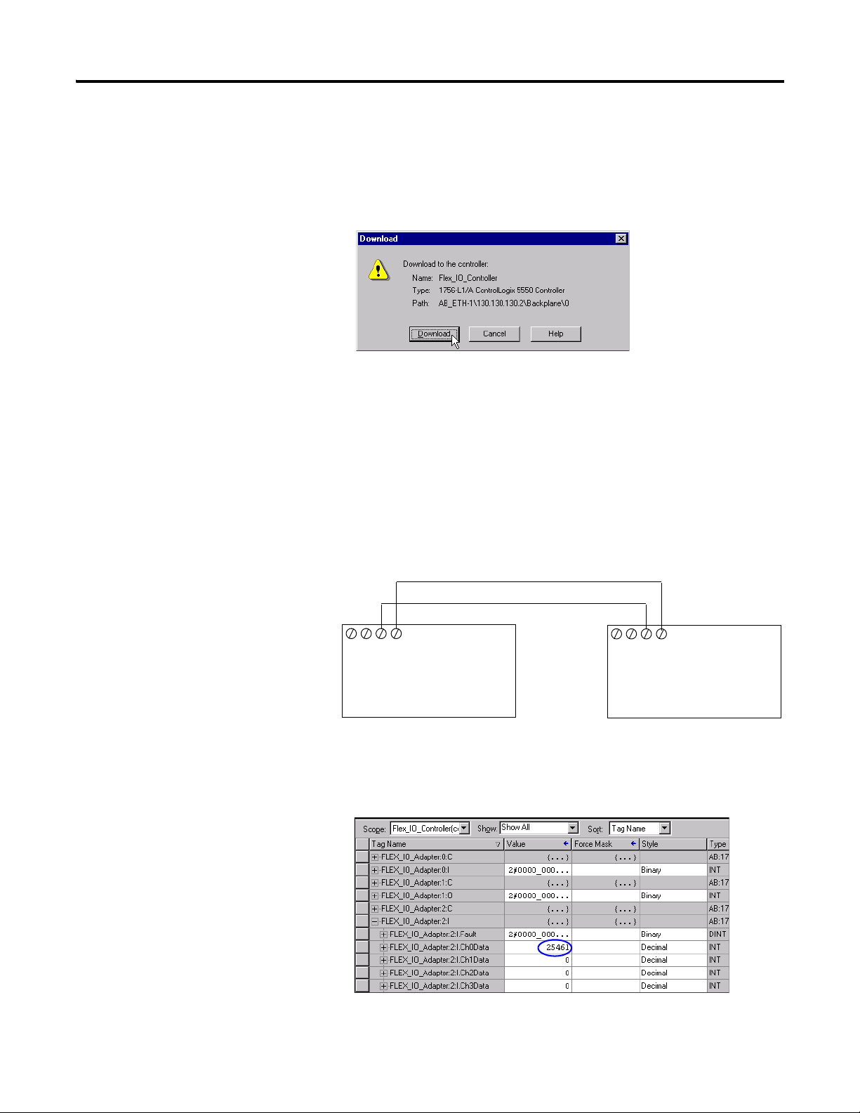
A Download dialog appears:
4. Click Download.
The program downloads to the controller.
5. Minimize the RSLogix 5000 software.
Test the example application by using a momentary switch to simulate a parts
sensor.
Publication 1794-UM066A-EN-P - February 2012
Page 44

36 Rack Optimized Discrete I/O
TIP
Count
Reset
24V
+
-
1794-IB16
16 (COM)
02
151413121110987654321
0
24 VDC SOURCE OUTPUT
1794±OB16
2
Allen-Bradley
LEDs on Output Module will increment in binary.
Accumulated Value will
increment and move to
Output Module.
1. Remove power from the FLEX I/O and wire inputs 0 and 2 of the
1794-IB16 FLEX I/O input module as shown in the following figure:
2. Restore power to the FLEX I/O.
3. Restore the RSLogix 5000 software window and place the controller in
Run mode.
4. Repeatedly press and release the momentary switch at Input 0 (Count) on
the 1794-IB16 input module.
Each time you press the switch the Parts_Count accumulated value
increments on the screen and the LEDs of the 1794-OB16 output module
increment in binary.
Chapter Summary
Publication 1794-UM066A-EN-P - February 2012
5. Press and release the momentary switch at Input 2 (Reset) on the
1794-IB16 input module.
The accumulated value of the Parts_Count reset to zero and all of the
LEDs on the 1794-OB16 output module turn off.
For more information on wiring and interpreting status LED
indicators on the I/O modules, refer to the I/O module publications
1794-IN093
and 1794-IN094.
This completes the Rack Optimized Discrete I/O example.
This chapter described how to set up and use rack optimized discrete I/O. The
next chapter describes how to add analog I/O modules to a configuration using
direct connection.
Page 45

Chapter
Analog I/O with Direct Connection
5
Overview
In this example you add analog input and output modules to the FLEX I/O
configured with two digital I/O modules in the previous chapter. Analog
modules default to direct connection, so you will open a direct connection to
each analog module while still using a single rack optimized connection for the
two digital I/O modules.
To test the system, the example of the previous chapter is modified to send a
signal to one of the analog output channels and read the signal back in through
one of the analog input channels.
Topic Page
Set Up the Hardware 37
Create the Example Application 38
Add the Analog Modules to the I/O Configuration 39
Add the Analog Input Module to the I/O Configuration 39
Add the Analog Output Module to the I/O Configuration 42
Edit the Controller Tags 45
Modify the Ladder Program 47
Download the Program 47
Test the Example Application 48
Set Up the Hardware
37 Publication 1794-UM066A-EN-P - February 2012
Change the system hardware setup of the previous chapter to that shown below,
adding the FLEX analog input and output modules to the DIN rail with the
1794-AENTR adapter and digital I/O modules.
Page 46

38 Analog I/O with Direct Connection
Local
Chassis
FLEX I/O
Logix5572
Controller
1794-OB16
Digital Output
1794-IB16
Digital Input
1756-EN2TR
130.130.130.2
1794-AENTR
130.130.130.3
Data
Programming
terminal
130.130.130.1
SLOT 1 2
SLOT 1 2
1794-OF4I
Analog
Output
1794-IF4I
Analog Input
• Note that in the example application, the Logix5572 controller and
1756-EN2TR module are in the slots shown above in the ControlLogix
chassis.
• Verify that the IP addresses for the 1756-EN2TR module, 1794-AENTR
adapter, and programming terminal are correct.
• Verify the position (slot) of the I/O modules on the DIN rail.
• Verify that all wiring and cabling is properly connected.
• Make sure you have your communication driver (for example, AB_ETH-1
or AB_ETHIP-1) configured in RSLinx as described in Appendix C
.
Create the Example Application
Publication 1794-UM066A-EN-P - February 2012
Perform the following steps to create the example application:
1. Start the RSLogix 5000 Enterprise Series software.
The RSLogix 5000 main dialog opens.
Page 47

Analog I/O with Direct Connection 39
IMPORTANT
2. Open the project file from the previous chapter (for example,
FLEX_IO_Controller).
3. Save the file using a different name (for example,
FLEX_IO_Controller_2).
Add the Analog Modules to the I/O Configuration
You must now add the analog I/O modules to the I/O Configuration. In this
example, you add a 1794-IF4I analog input module and a 1794-OF4I analog
output module. Use these steps as a guide when you are configuring different I/O
modules for your system.
Click Help on the configuration screens shown in this section if you
need assistance in selecting and setting the parameters.
Add the Analog Input Module to the I/O Configuration
Publication 1794-UM066A-EN-P - February 2012
Page 48
40 Analog I/O with Direct Connection
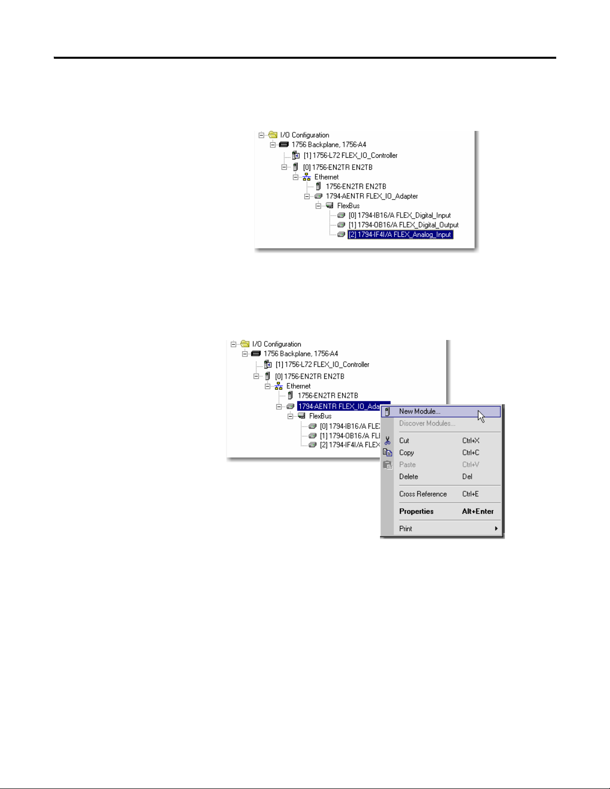
1. Right click the 1794-AENTR adapter under the I/O Configuration
folder, and then select New Module.
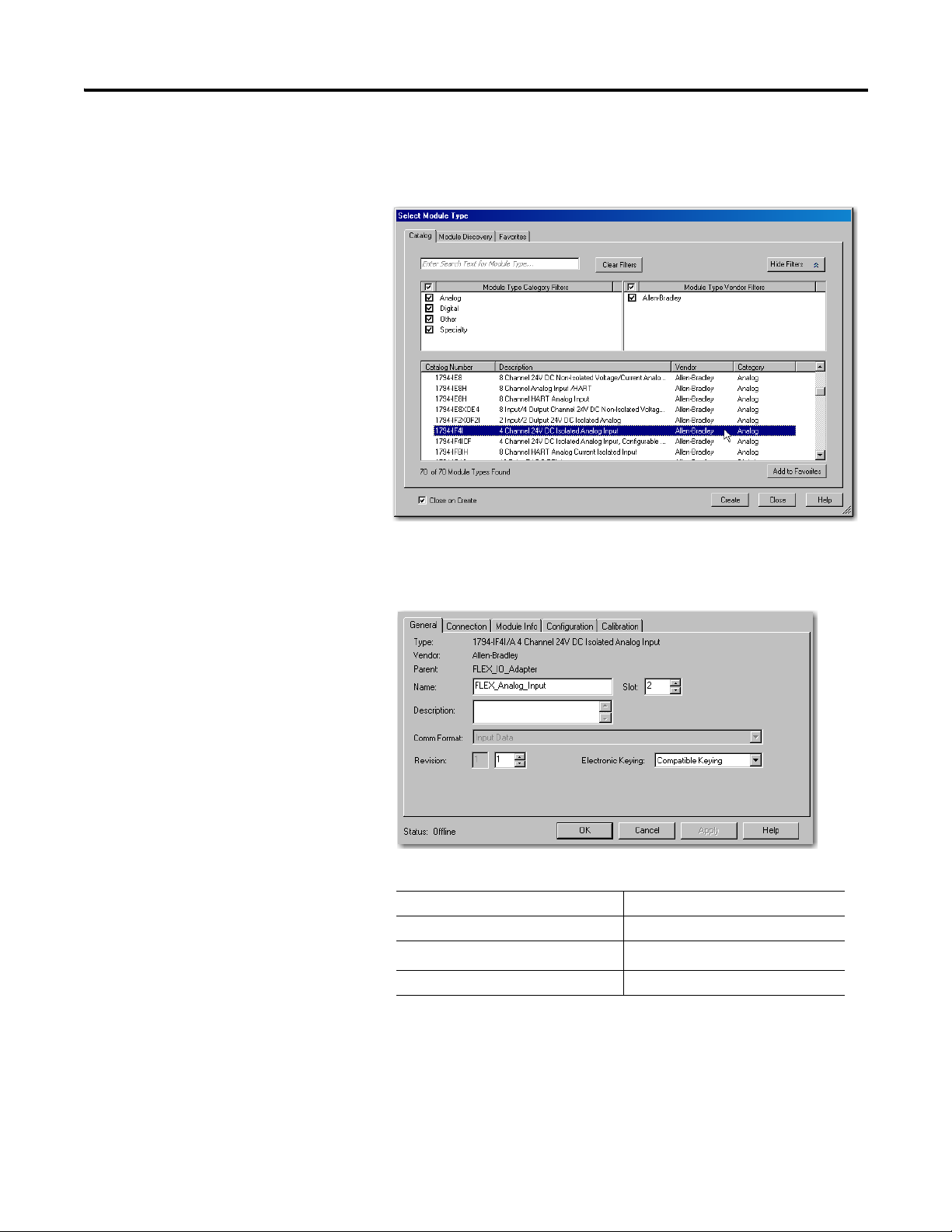
The Select Module Type window opens.
2. Select the 1794-IF4I/A analog input module from the list, and then
click Create.
The New Module dialog opens.
3. Enter the following parameters:
Name FLEX_Analog_Input
Slot 3
Comm Format
Input Data
Electronic Keying Compatible Module
(1)
All analog Comm Formats use direct connection. The default here is Input Data.
(1)
Publication 1794-UM066A-EN-P - February 2012
4. Click OK to save the configuration.
The Module Properties Report dialog opens.
Page 49
Analog I/O with Direct Connection 41
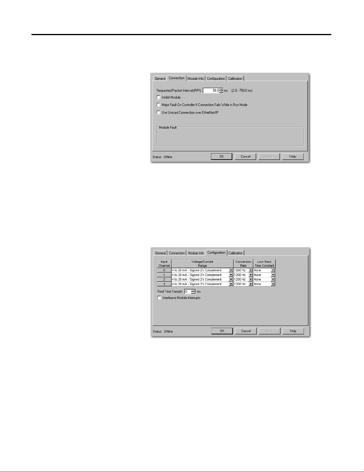
5. On the Connection tab, adjust the Requested Packet Interval (RPI) to
meet your system requirements.
For this example you can leave it at the default 50 ms rate.
This RPI is used for the direct connection to this analog module.
The two rack connected digital I/O modules continue to communicate at
the RPI of the rack connection.
6. Click Apply to save the configuration.
7. On the Configuration tab, use the pull-down list to set the
Voltage/Current Range for Channel 0 to 0 to 10V – Binary.
This range allows you to easily monitor the output with a voltmeter when
you test the application.
Leave the other channels at their default values.
Publication 1794-UM066A-EN-P - February 2012
Page 50
42 Analog I/O with Direct Connection
8. Click Apply to save the configuration, and then OK to close the dialog.
The analog input module appears in the I/O configuration indented
under the 1794-AENTR adapter.
Add the Analog Output Module to the I/O Configuration
1. Under the I/O Configuration folder, right-click the remote
1794-AENTR adapter, and then select New Module.
Publication 1794-UM066A-EN-P - February 2012
Page 51
Analog I/O with Direct Connection 43
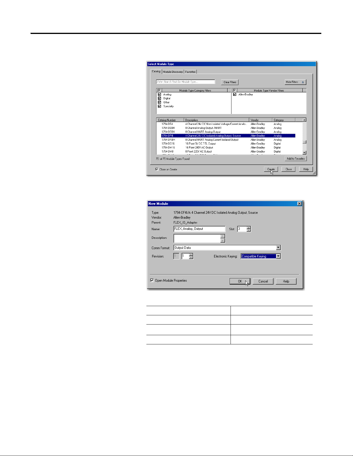
The Select Module Type window opens.
2. Select the 1794-OF4I module from the list, and then click Create.
The New Module dialog opens.
3. Enter the following parameters:
Name FLEX_Analog_Output
Slot 3
Comm Format
Output Data
Electronic Keying Compatible Module
(1)
All analog Comm Formats use direct connection. The default here is Output Data.
4. Click OK to save the configuration.
The Module Properties Report dialog opens.
Publication 1794-UM066A-EN-P - February 2012
(1)
Page 52
44 Analog I/O with Direct Connection
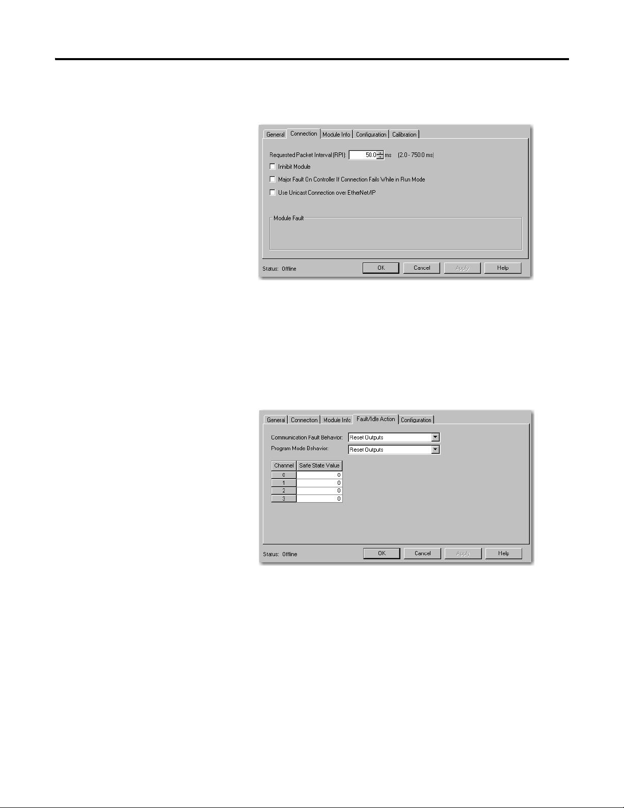
5. On the Connection tab, adjust the Requested Packet Interval (RPI) to
meet your system requirements.
For this example change the RPI to 50 ms rate.
This RPI is used for the direct connection to this analog module.
The two rack connected digital I/O modules continue to communicate at
the RPI of the rack connection.
6. Click Apply to save the configuration.
7. Click the Fault/Idle Action tab.
For this example, leave these parameters at the default setting.
For an explanation of these parameters click Help.
Publication 1794-UM066A-EN-P - February 2012
Page 53

Analog I/O with Direct Connection 45
8. On the Configuration tab, use the pull-down list to set the
Voltage/Current Range for Channel 0 to 0 to 10V – Binary to match the
input configuration of the 1794-IF4I module.
Leave the other channels at their default values.
9. Click Apply to save the configuration, and then OK to close the dialog.
The analog input module appears in the I/O configuration indented
under the 1794-AENTR adapter.
Edit the Controller Tags
When you add modules to the I/O configuration the system creates Controller
Tags for those modules. For the example program you need to add one more
Controller Tag.
Publication 1794-UM066A-EN-P - February 2012
Page 54
46 Analog I/O with Direct Connection
New tags created
by the system for
the analog modules
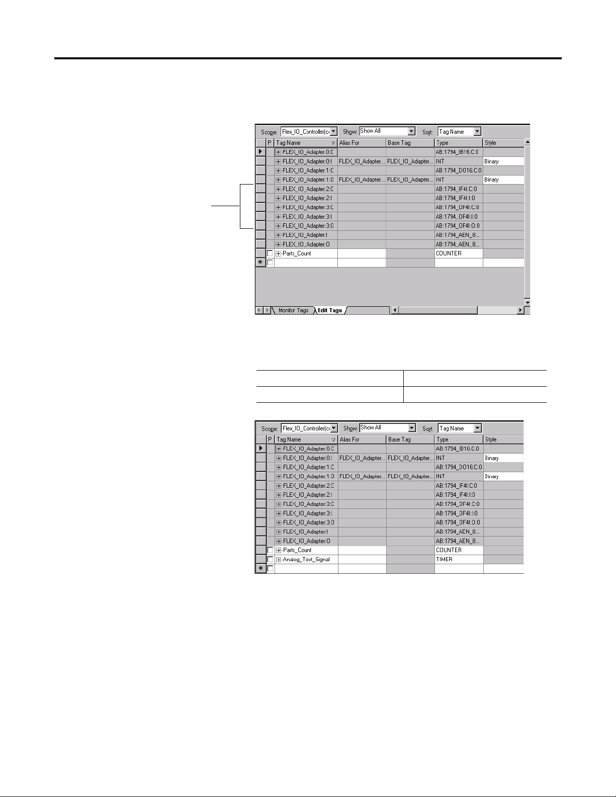
1. Double-click the Controller Tags folder in the project window.
Note that new tags have been added for the analog I/O modules.
Make sure you select the Edit Tags tab at the bottom of the Controller Tags
window, and then create the following tag:
Tag Ty pe
Analog_Test_Signal Tim er
Publication 1794-UM066A-EN-P - February 2012
Page 55
Analog I/O with Direct Connection 47
Modify the Ladder Program
Make the following change to the ladder program to test the new configuration.
2. Double-click Main Routine under the Main Program folder, and then add
rungs 3 and 4 to the ladder program.
3. Save the program.
Download the Program
To download the program to the controller do the following:
1. Click the Communications menu, and then select Who Active.
The Who Active window opens.
Publication 1794-UM066A-EN-P - February 2012
Page 56
48 Analog I/O with Direct Connection
VR
23
VR
23
1794-IF4I 1794-OF4I
2. Select your Ethernet driver (for example, AB_ETH-1) and expand the tree
through the backplane of the local ControlLogix chassis.
3. Highlight the controller. and then click Download to download the
program to the Logix5572 controller.
A Download dialog appears:
4. Click Download.
The program downloads to the controller.
5. Minimize the RSLogix 5000 software window.
Test the Example Application
Use the following procedure to test the operation of the FLEX analog input and
output modules:
1. Connect analog output channel 0 on the 1794-OF4I/A module to analog
input channel 0 on the 1794-IF4I/A input module.
2. Restore the RSLogix 5000 software window and place the controller in
Run mode.
3. Double-click the Controller Tags folder, and then select the Monitor tab.
Publication 1794-UM066A-EN-P - February 2012
Page 57

Analog I/O with Direct Connection 49
TIP
4. Monitor channel 0 of the 1794-IF4I input module
(FLEX_IO_Adapter:2.I.Ch0Data above).
The value slowly rises to approximately 32000, resets to zero, starts rising
again, and so on, as the output of the timer is received from the
1794-OF4I output module.
For information on wiring and troubleshooting the I/O modules,
refer to the FLEX I/O Analog I/O Module Installation Instructions,
publications 1794-IN037
and 1794-IN038.
This completes the Direct Connect Analog I/O example.
Chapter Summary
This chapter described how to set up and use analog I/O modules with direct
connection.
Publication 1794-UM066A-EN-P - February 2012
Page 58

50 Analog I/O with Direct Connection
Notes:
Publication 1794-UM066A-EN-P - February 2012
Page 59
Interpret Status Indicators
44560
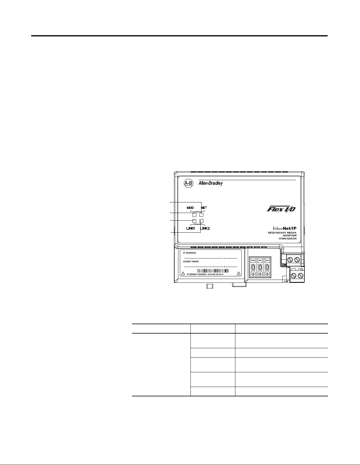
Network status
Module status
Link 1 status
Link 2 status
1794-AENTR shown
Appendix
A
Overview
Status Indicators
The faceplates of the 1794-AENT and 1794-AENTRXT adapters are provided
with status indicators that display the Module Status, Network Status, and Link
Status for both links.
1794-AENTR, 1794-AENTRXT Module
51 Publication 1794-UM066A-EN-P - February 2012
Use the following table to determine the indicator conditions and status.
Status Indicator Identification
Indicator State Status
Link 1 or Link 2 (individually) Off No link exists. Verify network cabling. Correct
as necessary.
Solid green Link exists at 100 Mbps.
Flashing green I/O is being transmitted or received at 100
Mbps.
Flashing yellow I/O is being transmitted or received at 10
Mbps.
Solid yellow Link exists at 10 Mbps.
Page 60

52 Interpret Status Indicators
Status Indicator Identification
Indicator State Status
Module Status Indicator Off No power. Adapter does not have 24V DC
power. Make sure power is being supplied to
the adapter.
Flashing green Standby. Adapter not configured. Configure
adapter.
Green Operational. Adapter operating correctly. No
action required.
Flashing red Minor fault. A recoverable fault has been
detected. This could be caused by an incorrect
or inconsistent configuration.
Check configuration and reconfigure as
needed.
Solid red Major fault. An unrecoverable fault has been
detected. Recycle power to the adapter. If this
does not clear the fault, replace the adapter.
Flashing red/green Self test. Adapter performing power-up self
test. Wait until completed.
Network Status Indicator Off Not powered. No IP address. Adapter is not
powered or does not have an IP address.
Verify there is power and the adapter is
correctly wired to the power supply.
Make sure the adapter is configured.
Flashing green No connection. Adapter has obtained an IP
address, but has no established connections.
Green CIP connections. Adapter has an IP address
and at least one established connection.
Flashing red Connection timeout. One or more of the
connections in which the adapter is the target
has timed out.
Red Duplicate IP address. Adapter has detected
that its IP address is already in use. Configure
the adapter with a unique IP address.
Flashing red/green Self-test. Adapter performing power-up self
test.
Chapter Summary
Publication 1794-UM066A-EN-P - February 2012
This appendix described how to troubleshoot your adapter module by
interpreting the status indicators.
Page 61

Specifications
Appendix
B
Overview
This appendix contains general and environmental specifications and
certifications for the FLEX I/O Dual Port EtherNet/IP Adapter Modules.
General Specifications – 1794-AENTR, 1794-AENTRXT
Specification 1794-AENTR 1794-AENTRXT
I/O capacity 8 modules
Power supply To comply with the CE Low Voltage Directive (LVD), this equipment must be
Input voltage rating,
nom
Input voltage range 19.2…31.2V DC (includes 5% AC ripple)
Inrush current 18 A for 2 ms
Communication rate 10/100 Mbps
Indicators Module status – red/green
FlexBus output, max 5.0V DC
Isolation voltage 50V (continuous), Basic Insulation Type
Power consumption,
max
Power dissipation,
max
Thermal dissipation 24.2 BTU/hr @ 19.2V DC
Ethernet connector RJ45 Cat. 5
Enclosure type rating None (open-style)
Wire size Power conductors:
Wiring category
North American temp
code
IEC temp code T5 T4
Terminal screw torque 0.8 Nm (7 lb-in.)
Weight, approx. 227 g (8.01 oz)
Dimensions, HxWxD,
approx.
(1)
Use this Conductor Category information for planning conductor routing. Refer to Industrial Automation Wiring
and Grounding Guidelines, publication 1770-4.1
(1)
powered from a source compliant with the following:
Safety Extra Low Voltage (SELV) or Protected Extra Low Voltage (PELV).
24V DC
Network status – red/green
Link 1 – yellow/green
Link 2 – yellow/green
640 mA
Tested @ 1000V AC for 60 s, power to FlexBus to EtherNet
500 mA,
400 mA @ 24V DC
7.1 W @ 19.2V DC
0.33…3.31 mm
(167 °F) or greater, 1.2 mm (3/64 in.) insulation max
1 – on power ports
2 – on communication ports
T5 T4A
87.4 x 94 x 92 mm
(3.44 x 3.7 x 3.6 in.)
2
(22…12 AWG) stranded copper wire rated @ 75 °C
.
53 Publication 1794-UM066A-EN-P - February 2012
Page 62

54 Specifications
Environmental Specifications – 1794-AENTR, 1794-AENTRXT
Specification 1794-AENTR 1794-AENTRXT
Temperature,
operating
Temperature,
surrounding air, max
Temperature,
nonoperating
Relative humidity IEC 60068-2-30 (Test Db, Unpackaged Damp Heat):
Vibration IEC60068-2-6 (Test Fc, Operating):
Shock, operating IEC 60068-2-27 (Test Ea, Unpackaged Shock):
Shock, nonoperating IEC 60068-2-27 (Test Ea, Unpackaged Shock):
Emissions CISPR 11:
ESD immunity IEC 61000-4-2:
Radiated RF immunity IEC 61000-4-3:
EFT/B immunity IEC 61000-4-4:
Surge transient
immunity
Conducted RF
immunity
IEC 60068-2-1 (Test Ad, Operating Cold),
IEC 60068-2-2 (Test Bd, Operating Dry Heat),
IEC 60068-2-14 (Test Nb, Operating Thermal Shock):
0…55 °C (32…131 °F) -25 …70 °C (-13…158 °F)
55 °C (131 °F) 70 °C (158 °F)
IEC 60068-2-1 (Test Ab, Unpackaged Nonoperating Cold),
IEC 60068-2-2 (Test Bb, Unpackaged Nonoperating Dry Heat),
IEC 60068-2-14 (Test Na, Unpackaged Nonoperating Thermal Shock):
-40…85 °C (-40…185 °F)
5 …95% non-condensing
5 g @ 10…500 Hz
30 g
50 g
Group 1, Class A
6 kV contact discharges
8 kV air discharges
10V/m with 1 kHz sine-wave 80% AM from 30…2000 MHz
10V/m with 200 Hz 50% Pulse 100% AM at 900 MHz
10V/m with 200 Hz 50% Pulse 100% AM at 1890 MHz
10/m with 1 kHz sine-wave 80% AM from 2000…2700 MHz
±4 kV at 5 kHz on power ports
±4 kV at 5 kHz on communication ports
IEC 61000-4-5:
±1 kV line-line (DM) and ±2 kV line-earth(CM) on power ports
±2 kV line-earth(CM) on communication ports
IEC 61000-4-6:
10V rms with 1 kHz sine-wave 80% AM from 150 kHz…80 MHz
Publication 1794-UM066A-EN-P - February 2012
Page 63

Certifications
Specifications 55
Certifications (when
product is marked)
Value
(1)
c-UL-us UL Listed Industrial Control Equipment, certified for US and Canada. See
UL File E322657.
UL Listed for Class I, Division 2 Group A,B,C,D Hazardous Locations,
certified for U.S. and Canada. See UL File E334470.
CE European Union 2004/108/EC EMC Directive, compliant with:
EN 61326-1; Meas./Control/Lab., Industrial Requirements
EN 61000-6-2; Industrial Immunity
EN 61000-6-4; Industrial Emissions
EN 61131-2; Programmable Controllers (Clause 8, Zone A & B)
C-Tick Australian Radiocommunications Act, compliant with:
AS/NZS CISPR 11; Industrial Emissions
Ex European Union 94/9/EC ATEX Directive, compliant with:
EN 60079-15; Potentially Explosive Atmospheres, Protection "n"
EN 60079-0; General Requirements
EN 60079-11; Explosive Atmospheres, Protection "i"
II 3 G Ex ic nA IIC T5 Gc – for 1794-AENTR only
II 3 G Ex ic nA IIC T4 Gc – for 1794-AENTRXT only
TÜV TÜV Certified for Functional Safety:
Capable of SIL 2
EtherNet/IP ODVA conformance tested to EtherNet/IP specifications
KC Korean Registration of Broadcasting and Communications Equipment,
compliant with:
Article 58-2 of Radio Waves Act, Clause 3
(1)
See the Product Certification link at www.ab.com for Declarations of Conformity, Certificates, and other
certification details.
WARNING: For Class I Division 2 applications, use only Class I
Division 2 listed or recognized accessories and modules approved
for use within the 1794 platform.
Publication 1794-UM066A-EN-P - February 2012
Page 64

56 Specifications
Notes:
Publication 1794-UM066A-EN-P - February 2012
Page 65

Configure the RSLinx Ethernet
Communication Driver
Appendix
C
Overview
About the Etherner Communication Driver
Install the RSLinx Software
Read this appendix to install, and configure the AB_ETH driver.
For Information On Page
About the Etherner Communication Driver
Install the RSLinx Software
Configure the AB_ETH Driver 57
In order to communicate with your 1794-AENTR or 1794-AENTRXT adapters
over your network you must configure the RSLinx Ethernet communication
driver (AB_ETH). You can configure the AB_ETH driver with the IP addresses
of all the Ethernet devices on your system. You will need this driver to download
the example application programs in this manual.
Use the following procedure to install RSLinx software on your computer.
1. Insert the CD in the CD-ROM drive.
Note: The CD-ROM supports Windows Autorun. Once inserted into the
CD-ROM drive, if you have Autorun configured, the installation will
automatically start at the first setup screen.
57
57
If Autorun is not configured for your CD-ROM drive, go to step 2.
2. From the Start menu, choose Run.
The Run pop-up window appears.
3. Type D:/setup (if it doesn’t appear automatically), where D: is your
CD-ROM driver letter.
4. Click OK.
The progress bar appears, followed by the welcome screen.
Configure the AB_ETH Driver
57 Publication 1794-UM066A-EN-P - February 2012
To configure the AB_ETH Ethernet communication driver perform the
following steps:
Page 66
58 Configure the RSLinx Ethernet Communication Driver
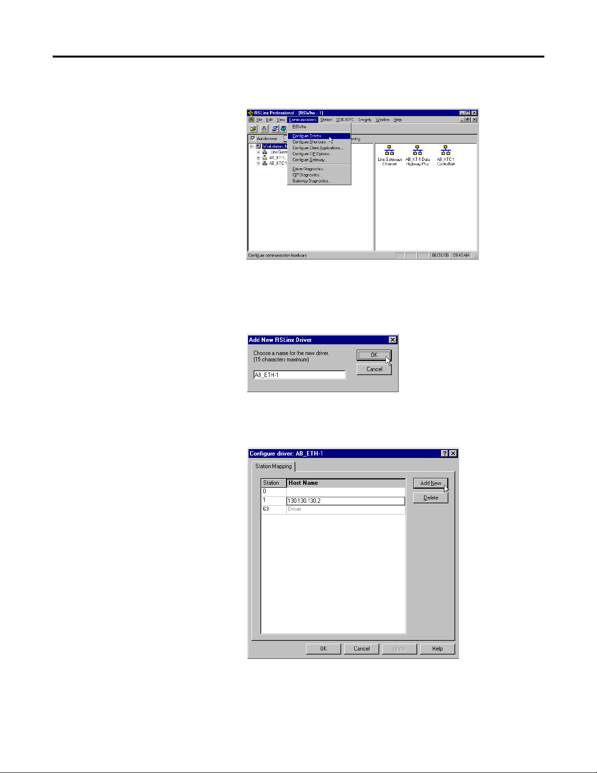
1. Start RSLinx.
2. From the Communications menu, select Configure Drivers.
3. From the Available Driver Types drop down menu, select Ethernet
Devices, and then click Add/New.
The Add New RSLinx Driver dialog box appears.
4. Select the default driver name (for example, AB_ETH-1) or type in your
own name and click OK.
The Configure driver dialog appear with the Station Mapping tab open.
5. Click Add New and enter the IP address or Host Name of your Ethernet
device (for example, 130.130.130.2, “Pump1”).
Publication 1794-UM066A-EN-P - February 2012
6. Repeat step 5 for each additional Ethernet device you need to access.
Page 67
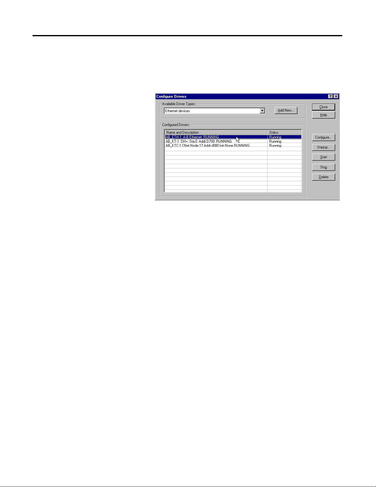
Configure the RSLinx Ethernet Communication Driver 59
7. When you are done entering the IP addresses, click Apply and then click
OK to close the Configure driver window.
The new driver appears in the list of configured drivers. Your list displays
the drivers you have configured on your workstation.
8. Close RSLinx.
Publication 1794-UM066A-EN-P - February 2012
Page 68

60 Configure the RSLinx Ethernet Communication Driver
Notes:
Publication 1794-UM066A-EN-P - February 2012
Page 69

Adapter Web Dialogs
IMPORTANT
Appendix
D
Overview
Work with the Home Page
The Web server dialog of the FLEX I/O adapter offers extensive internal and
network diagnostics. To view the Web dialogs, enter the IP address of the
FLEX I/O adapters into your browser.
Topic Page
Work with the Home Page 61
Work with the Diagnostics Pages 63
Use the Diagnostic Overview Page 64
Use the Network Configuration Page 70
Use the Ethernet Statistics Page 66
Use the I/O Connections Page 67
Work with the Configuration Pages 68
Use the Device Identity Page 69
Use the Network Configuration Page 70
Use the Device Services Page 72
Use the adapter diagnostics home page to access other adapter diagnostics web
pages and see the following information.
• ModuleName
• Module Description
• Module Location
• IP Address
• Ethernet Address (MAC)
• DHCP Enabled
• Status
• Serial Number
• Product Revision
• Firmware Version Date
To display and work with the adapter diagnostics home page, follow these
procedures.
Make sure that your PC Internet LAN setting and your TCP/IP settings are
configured to access the subnet on which your adapter communicates.
61 Publication 1794-UM066A-EN-P - February 2012
Page 70
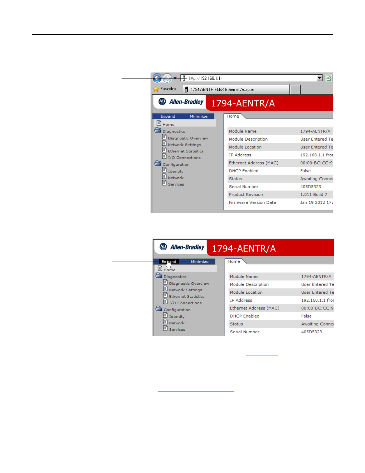
62 Adapter Web Dialogs
Enter the adapter IP address
to see the home page.
Click Expand to show
options.
1. From your web browser, enter the adapter IP address to see the Home
page.
2. From the Home page, click Expand to show options, or minimize to see
Diagnostics and Configuration.
3. From the Home page, complete one of these, as desired.
• Click one of the following to access www.ab.com
.
– Allen-Bradley logo at the top of the page
– AB.com link under Resources on the right hand side of the page
• Click Rockwell Automation at the top right to go to
www.rockwellautomation.com
.
• Click the following to see additional diagnostics web pages.
– Diagnostics – Diagnostic overview, Network Settings, Ethernet
Statistics, I/O Connections
– Configuration – Identity, Network, Services
Publication 1794-UM066A-EN-P - February 2012
Page 71
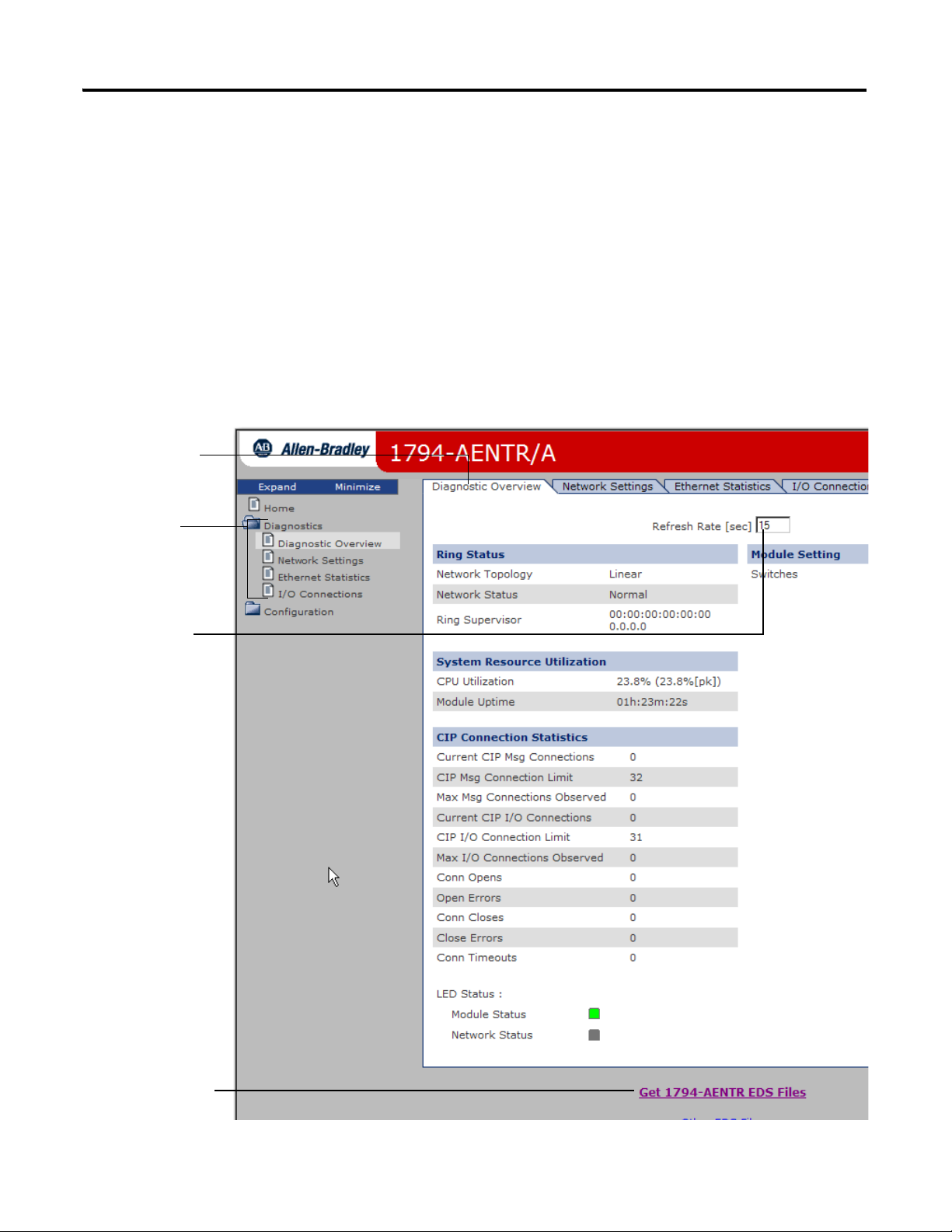
Adapter Web Dialogs 63
Click tabs to see the
corresponding page.
Type a refresh rate.
Click Diagnostics
options to see
corresponding pages
Download EDS files for
your adapter
Work with the Diagnostics Pages
To work with the Diagnostics options, follow these procedures.
1. From the Home page, click Diagnostics or Expand to see the following
diagnostics options from the panel at the left.
•Diagnostic Overview
•Network Settings
• Ethernet Statistics
•I/O Connections
2. In the Refresh Rate field, you can type a refresh rate, noting that the
default rate is 15 seconds.
3. From the panel at the left or tabs at the top of the page, click one of the
diagnostics options to see the corresponding page.
Publication 1794-UM066A-EN-P - February 2012
Page 72

64 Adapter Web Dialogs
Use the Diagnostic Overview Page
To use the Diagnostic Overview page for general diagnostics information, click
Diagnostic Overview from the tab at the top of the page or panel on the left.
From the Diagnostic Overview page, you can view the following:
•Ring Status
–Network Topology
–Network Status
–Ring Supervisor
• System Resource Utilitization
– CPU Utilization
–Module Uptime
• CIP Connection Statistics
–Current CIP MSG Connections
–CIP MSG Connection Limit
– Max Msg Connections Observed
–Current CIP I/O Connections
–CIP I/O Connection Limit
– Max I/O Connections Observed
–Conn Opens
–Open Errors
– Conn Closes
– Close Errors
– Conn Timeout
•Module Settings
–Switches
Publication 1794-UM066A-EN-P - February 2012
Page 73
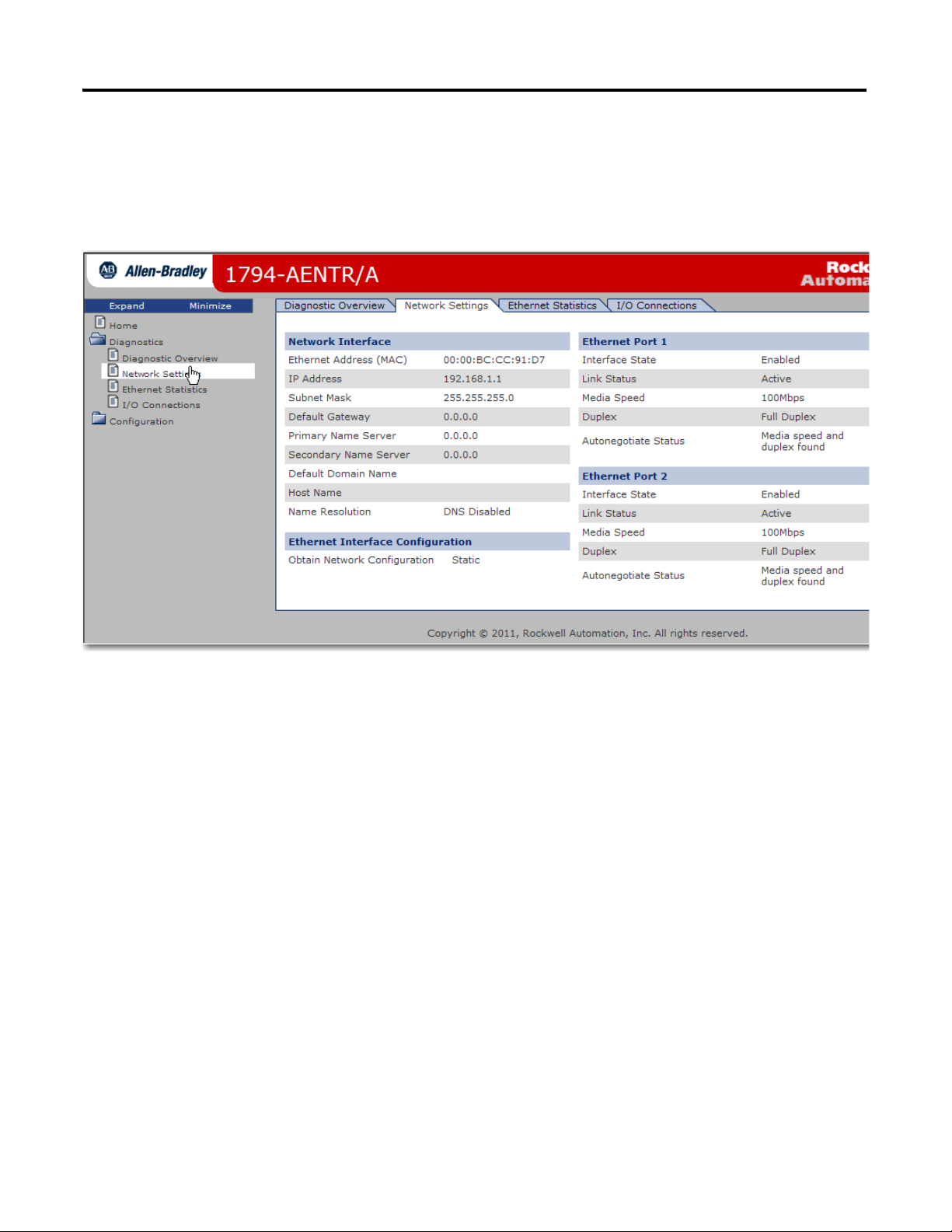
Adapter Web Dialogs 65
Use the Network Settings Page
To use the Network Settings page for network related information, click
Network Settings tab at the top of the page or panel on the left.
This opens the Network Settings page.
From the Network Settings page, you can view the following:
•Network Interface
– Ethernet Address (MAC)
–IP Address
–Subnet Mask
–Default Gateway
–Primary Name Server
–Secondary Name Server
–Default Domain Name
–Host Name
– Name Resolution
• Ethernet Interface Configuration
– Obtain Network Configuration
•Ethernet Port 1 and 2
–Interface State
–Link Status
– Media Speed
–Duplex
– Autonegotiate Status
Publication 1794-UM066A-EN-P - February 2012
Page 74

66 Adapter Web Dialogs
Use the Ethernet Statistics Page
To use the Ethernet Statistics page for information about the Ethernet link and
interface and media counters, click Ethernet Statistics tab at the top of the page or
from the panel on the left.
The Ethernet Statistics page opens.
Publication 1794-UM066A-EN-P - February 2012
From the Ethernet Statistics page, you can view the following:
• Ethernet Port 1 and Port 2
–Interface State
–Link Status
– Media Speed
–Duplex
– Autonegotiate Status
• Media Counters Port 1 and Port 2
–Alignment Errors
Page 75
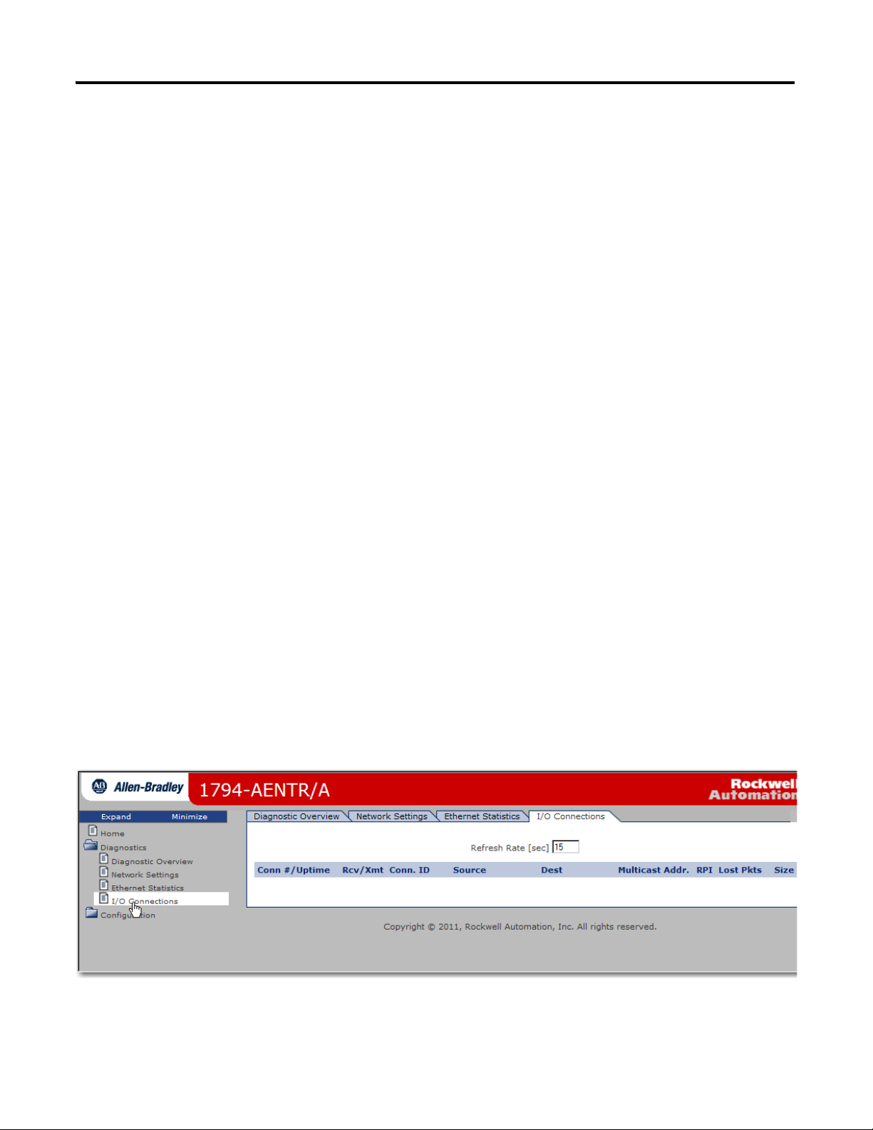
–FCS Errors
– Single Collisions
–SQE Test Errors
– Deferred Transmissions
– Late Collisions
– Excessive Collisions
–MAC Transmit Errors
– Carrier Sense Errors
–Frame Too Long
– MAC Receive Errors
• Interface Counters
– In Octets
– In Ucast Packets
– In NUcast Packets
–In Discards
– In Errors
–In Unknown Protos
–Out Octets
– Out UCast Packets
– Out NUcast Packets
–Out Discards
–Out Errors
Adapter Web Dialogs 67
Use the I/O Connections Page
To use the I/O Connections page for CIP I/O (Class 1) connection information,
click I/O Connections tab at the top of the page or panel on the left.
The I/O Connections page opens.
From the I/O Connections page, view the following:
• Connection Number / Uptime
Publication 1794-UM066A-EN-P - February 2012
Page 76

68 Adapter Web Dialogs
IMPORTANT
IMPORTANT
• Received / Transmitted packets
• Connection ID
•Source
•Destination
• Multicast Address
•RPI
• Lost Packets
•Size
Work with the Configuration Pages
To work with the Configuration pages, follow these procedures.
The values on these pages are in non-volatile memory. Changes to these
parameters do not take effect until you reset or cycle power through the
FLEX I/O adapter.
If you set the value of the adapter switch to 888 and then power cycle the
module, the following occurs:
• The DHCP Enabled function is enabled (set to True).
• The Ethernet link is negotiated automatically. The Auto Negotiate
function is set to True.
• The web server is enabled. The Disabled Web Server function is
disabled.
• The Ethernet port are disabled. Both ports are re-enabled once the
switches are returned to their previous value and power is cycled.
• The password for this page resets to the factory default which is
"<blank>".
Note the value of the switches before you enter the 888 value because
you must return the adapter to those values once this process is
complete.
1. From the Home page, click Configuration or Expand to see the
Configuration options, if needed.
2. From the Configuration page, click one of the following:
•Identity
•Network
•Services
Publication 1794-UM066A-EN-P - February 2012
Page 77

Adapter Web Dialogs 69
A login dialog opens as shown. The dialog may vary in appearance
depending on your operating system and browser.
3. From the user name and password dialog, enter values, noting the
following:
• The values for user name and password are case sensitive.
• The default user name is “Administrator”.
•The default password is "<blank>".
4. Click OK to log in. After you log in, you can go to any of the
Configuration pages without having to log in again.
5. Refer to the section of this manual that corresponds to the section you
clicked:
•Identity
• Network Configuration
• Services
Use the Device Identity Page
To use the Device Identity page to make entries for the device name, device
description, and device location, click Device Identity from the tab at the top of
the page or panel on the left.
Publication 1794-UM066A-EN-P - February 2012
Page 78

70 Adapter Web Dialogs
The Identity page opens.
From the Identity page, complete entries for the following, noting that the
description and location help you identify where modules are in the facility:
•Host Name
•Module Description
•Module Location
6. Click Apply Changes to save the modified values.
Use the Network Configuration Page
To use the Network Configuration page to make entries for enabling or disabling
DHCP and setting TCP/IP parameters and Ethernet link operation, click
Network Configuration tab at the top of the page or panel on the left.
Publication 1794-UM066A-EN-P - February 2012
Page 79

The Network Configuration page opens.
Adapter Web Dialogs 71
From the Network Configuration page, complete these entries, noting that values
for Network Interface are disabled when DHCP is Dynamic DHCP and port
speed and duplex mode are disabled when Autonegotiate Speed and Duplex is
selected.
• For Initial Network Configuration:
– Ethernet Interface Configuration
- Static
- Dynamic DHCP
• For Network Interface, fill out these fields:
–IP Address
–Subnet Mask
–Gateway Address
–Primary Name Server
Publication 1794-UM066A-EN-P - February 2012
Page 80
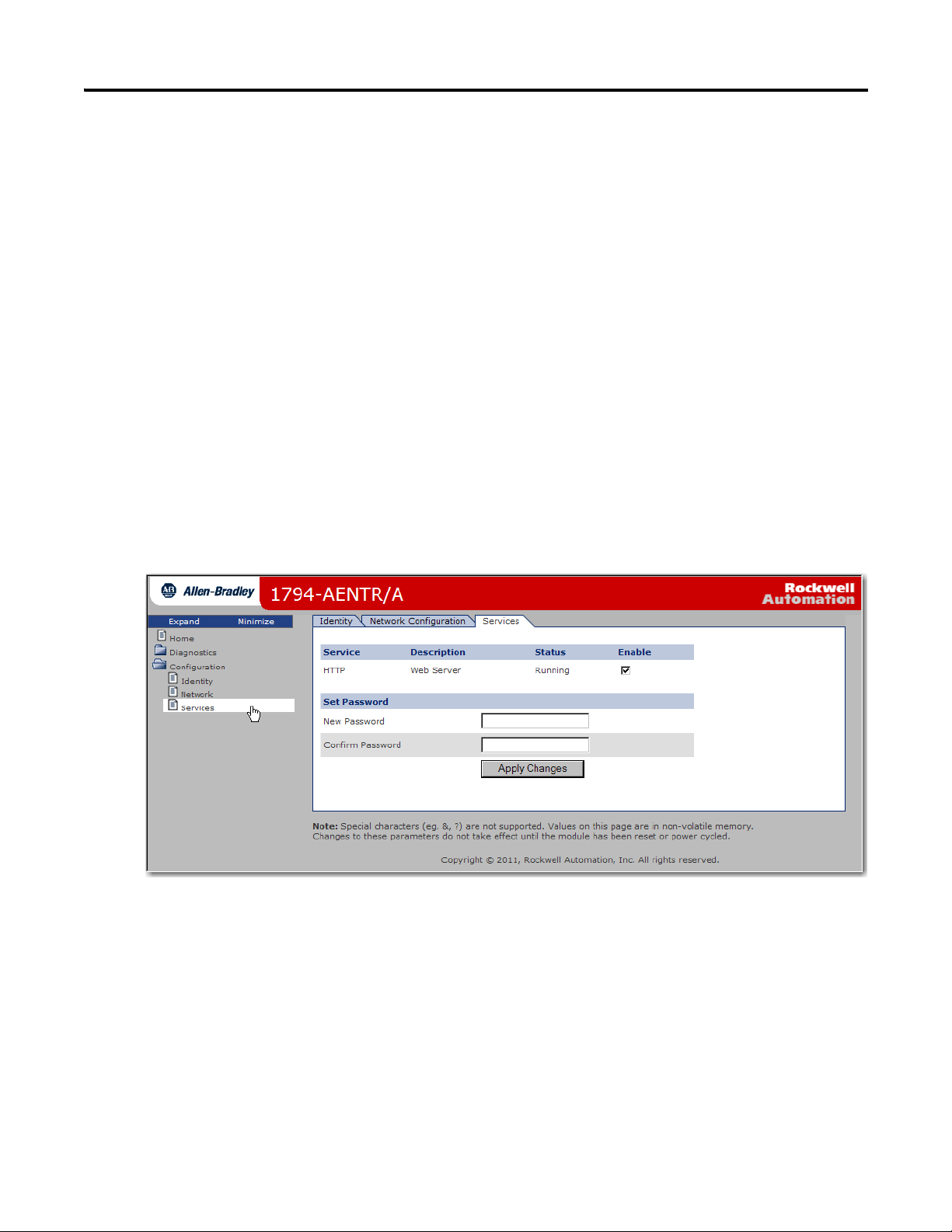
72 Adapter Web Dialogs
–Secondary Name Server
–Domain Name
• For Ethernet Link Port 1 and Port 2, specify the following:
– Autonegotiate Status
- Autonegotiate Speed and Duplex
- Force Speed and Duplex
– Select Port Speed – 10 megabits, 100 megabits
– Select Duplex Mode – Half Duplex, Full Duplex
7. From the Network Configuration page, click Apply Changes to save the
modified values.
Use the Device Services Page
To use the Services page to change the password for the Configuration web page
or disable the web server, click Device Services tab at the top of the page or panel
on the left.
The Device Services page opens.
From the Services page, make these entries.
• Click the Enable box to change whether the web server runs after the
module is reset.
• Change the password by typing a new value for New Password and
Confirm Password, noting the following:
– The entry is case sensitive.
– The default value is <blank>.
Publication 1794-UM066A-EN-P - February 2012
8. Click Apply Changes.
Page 81

Index
Numerics
1756-EN2TR 24, 38
module 28, 38
1756-EN2TR bridge 27
1756-EN2TR module 24, 28, 38
1794-IB16 24
A
AB_ETH 35, 38, 48, 57, 58
configured 24
ethernet communication driver 57
adapter 1, 7
1794-AENTR iii, 2, 3, 5, 7, 15, 23, 24, 26, 27, 28, 29, 30,
33, 37, 38, 40, 42, 45, 51, 57
1794-AENTRXT iii, 2, 3, 5, 7, 15, 57
add 27
bridge 3
cabling components 2
child 27
CIP protocol 3
communicating through 5
compatibility 2
connect or disconnect 9
connection to 5
diagnostics 61
EDS file 63
Ethernet hardware address 15
faceplate 51
features 2
fixed network address 22
FLEX I/O iii, 1, 7
FlexBus 9
hook 8
install 7
IP address 22, 62
lock 10
module 2
mount 8, 9, 23
position 8
rack optimized 23
refers to 2
remove 9
remove or replace 8
replace 9
RPI 4, 5
RPI rate 5
subnet mask 12
support 4
unique IP address 15
web server dialog 61
wiring 8
adapter module 1
address
default 16
ethernet 19
Ethernet hardware 15
gateway 12, 15, 16
hardware 19
host ID 17
IP 2, 12, 15, 16, 57
MAC 17
network 12, 18, 22
node 12
analog I/O module 39
B
BootP 21
protocol 15
utility 15
BootP utility 15
BootP/DHCP
utility 18
BootP/DHCP utility 18
bridge
1756-EN2TR 23, 27
bridge module 4
bridging module 3
C
capacity
module 2
communicate 1
programmable controllers 1
communication driver 24, 38
compatibility
hardware 2
software 2
configuration
device identity 69
identity 68
network 68
network configuration 70
services 68
configuration data 1
configure
1756-EN2TR 27
AB_ETH driver 57
BootP/DHCP 18
digital I/O 37
direct communication 5
ethernet communications driver 57
Publication 1794-UM066A-EN-P - February 2012
Page 82

74 Index
gateway 18
gateway address 15
IP address 15
new adapter 15
rack connection 23
routing tables 3
RPI 5
RSLinx 24, 38
subnet mask 15
TCP/IP settings 61
configure driver
window 59
connection
adjacent 9
backplane 9
direct 4, 37, 41, 44
I/O 62
power wiring 9
rack 41, 44
rack optimized 4, 23
single 5
connection point 9
connections
8 4
I/O 63
connector
FlexBus 9
controller
Logix5572 23
conventions iv
corresponding IP address 20
D
data 24
configuration 1, 4
consumed 4
exchange 4
I/O 3, 5
input 3
messaging 3
output 43
produce 4
read 23
send 23
transfer 4
data input 40
data transfer
real time 4
default address 16
description 20
device identity
host name 70
module description 70
module location 70
device services
enable 72
new password 72
DHCP 21
DHCP enabled 61
diagnostic overview 63
diagnostics
options 63
dimensions
1794-AENTR 13
1794-AENTRXT 13
mounting 13
DIN rail 2, 7, 10, 23, 24, 37, 38
mounting 2
top-hat 8
direct connection 4
discrete
I/O modules 5
driver
configure 59
duplex
full 2
half 2
dynamic allocation
network address 22
E
EDS file
adapter 63
Electronic Keying 27
ethernet address (MAC) 19
Ethernet device 58
ethernet statistics 63
ethernet port 1 66
ethernet port 2 66
interface counters 67
media counters 66
example
direct connection 37
rack optimized 23
F
faceplate
adapter 51
features
adapter 2
firmware
upgrades 2
Publication 1794-UM066A-EN-P - February 2012
Page 83

Index 75
FLEX I/O 23
adapter 1
description 1
I/O module 1
module components 7
system 1
terminal base 1
FLEX I/O module 2, 29
FLEX I/O system 1
components 1
definition 1
FlexBus connector 9
G
gateway 16
gateway address 12, 15, 16
configure 15
H
hardware
compatibility 2
hardware address 19
Host ID 16
host ID address 17
host name 58
hostname 20
I
I/O connections 63
connection ID 68
connection number 67
destination 68
lost packets 68
mulitcast addresss 68
received packets 68
RPI 68
size 68
source 68
transmitted packets 68
uptime 67
I/O data 3, 5
real time 3
I/O module 1, 3, 4, 5, 8, 26
indicators
status 7, 51
input data 40
input module 3, 23, 29
install
physically 7
Internet Protocol
IP 12
invalid number
thumbwheel switches 12
IP
Internet Protocol 12
IP Address 19, 27
IP address 2, 12, 15, 16, 17, 20, 57, 58, 61, 62
adapter 22
class 16
configure 15
corresponding 20
dotted-decimal 16
gateway 17
retrieve 12
switches 7
unique 15, 16
verify 24, 38
IP network 15
L
LED indicators
interpret 36
locking tab 10
M
MAC address 17
manuals
related iv
messaging
direct connection 4
module 8
1756-EN2TR 24, 26, 27
1794-IB16 23, 29, 30, 36
1794-IF4I 45
1794-OB16 23, 29, 32, 36
1794-OF4I 43
adapter 1
analog I/O 39
analog input 39
analog output 42
bridge 4
bridging 3
capacity 2
components 7
configurations 29
definition 28
description 61
digital input 23
digital output 23
dimensions 13
Publication 1794-UM066A-EN-P - February 2012
Page 84

76 Index
FLEX I/O 2, 29
I/O 1, 3, 4, 5, 8, 26
input 3, 23, 29, 37
input, add 30
insert or remove 9
latching mechanism 9
location 61
locking tab 7
name 61
output 23, 29, 37
output, add 31
reinstall 10
settings 64
type 26
uptime 64
module capacity 2
module description 61
module location 61
module name 61
module settings 64
module type 26
module uptime 64
modules
analog input 37
analog output 37
N
Net ID 16
net ID 17, 18
network 3
cable 11
devices 3
EtherNet/IP 3, 4, 7
scheduling 2
TCP/IP 21
traffic 3
network address 12, 18, 22
network cable 11
network configuration
ethernet link port 1 72
ethernet link port 2 72
initial 71
netowrk interface 71
network scheduling 2
network settings 63
ethernet interface configuration 65
ethernet port 1 65
ethernet port 2 65
network interface 65
networking
consumer 3
node address 12
set 12
O
output data 43
output module 23, 29
overview
diagnostic 63
P
power supply 23
Protocol
Dynamic Host Configuration (DHCP) 12, 21
Internet (IP) 12
protocol
application layer 3
BootP 15
CIP 3
message based 3
TCP/IP iii
TCP/UDP/IP 2
publications
download iv
related iv
view iv
purpose of this manual iii
R
rack optimized
connection 23
real time
data transfer 4
refresh rate 63
RPI 41
RSLinx 38
S
settings
network 63
software
compatibility 2
statistics
ethernet 63
status
link 51
module 51
network 51
Publication 1794-UM066A-EN-P - February 2012
Page 85

Index 77
status indicators 7, 51
subnet mask
configure 15
switches
IP address 7
thumbwheel 12
T
TCP/IP
network 21
protocol iii
terminal base 1, 2, 9
adjacent 9, 10
unit 9
thumbwheel
settings 12
switches 12
thumbwheel switches
invalid number 12
read 12
transfer data 4
U
unique
48-bit hardware address 15
combination of bits 18
IP address 15, 52
unique IP address 15
W
web dialogs
CIP connection statistics 64
configuration 68
diagnostic overview 63, 64
ethernet statistics 63, 66
home page 61
I/O connections 63, 67
module settings 64
network settings 63, 65
password 69
ring status 64
system resource utilization 64
user name 69
web server 61
Publication 1794-UM066A-EN-P - February 2012
Page 86

78 Index
Notes:
Publication 1794-UM066A-EN-P - February 2012
Page 87

Page 88

Rockwell Otomasyon Ticaret A.Ş., Kar Plaza İş Merkezi E Blok Kat:6 34752 İçerenköy, İstanbul, Tel: +90 (216) 5698400
Rockwell Automation Support
Rockwell Automation provides technical information on the Web to assist you in using its products.
http://www.rockwellautomation.com/support/, you can find technical manuals, a knowledge base of FAQs, technical and
At
application notes, sample code and links to software service packs, and a MySupport feature that you can customize to make
the
best use of these tools.
For an additional level of technical phone support for installation, configuration, and troubleshooting, we offer
Te c h C o n n e c t
support programs. For more information, contact your local distributor or Rockwell Automation representative,
or visit
Installation Assistance
If you experience a problem within the first 24 hours of installation, review the information that is contained in this
manual.
You can contact Customer Support for initial help in getting your product up and running.
United States or Canada 1.440.646.3434
Outside United States or
Canada
http://www.rockwellautomation.com/support/.
Use the Worldwide Locator
your local Rockwell Automation representative.
at http://www.rockwellautomation.com/support/americas/phone_en.html, or contact
New Product Satisfaction Return
Rockwell Automation tests all of its products to ensure that they are fully operational when shipped from the
manufacturing facility. However, if your product is not functioning and needs to be returned, follow these procedures.
United States Contact your distributor. You must provide a Customer Support case number (call the phone number above to obtain
Outside United States Please contact your local Rockwell Automation representative for the return procedure.
one) to your distributor to complete the return process.
Documentation Feedback
Your comments will help us serve your documentation needs better. If you have any suggestions on how to improve this
document, complete this form, publication
RA-DU002, available at http://www.rockwellautomation.com/literature/.
Publication 1794-UM066A-EN-P - February 2012
Copyright © 2012 Rockwell Automation, Inc. All rights reserved.
 Loading...