

Page 1
Installation Instructions
FLEX I/O ControlNet Redundant Media
Adapter
(Cat. No. 1794-ACNR)
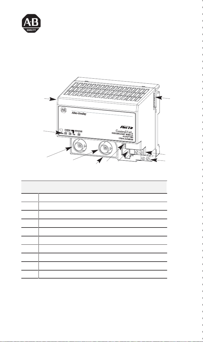
1
2
3a
1 ControlNet
2 Indicators
3a
ControlNet network cable BNC connector A
3b
ControlNet network cable BNC connector B (1794-ACNR15 only)
4
ControlNet Node selection thumbwheel switches
5
ControlNet programming terminal connector port
6
Module locking tab
7 +24V dc connections
8
24V common connections
9
Flexbus connector
3b
6
Component Identification
Adapter module
45
9
8
7
FLEX I/O is a trademark of Rockwell Automation.
Publication
1794-5.18 – September 1996
Page 2
FLEX I/O ControlNet Redundant Media Adapter2
European
If this product has the CE mark it is approved for installation within the
European Union and EEA regions. It has been designed and tested to meet
the following directives.
Union Directive Compliance
EMC Directive
This product is tested to meet Council Directive 89/336/EEC
Electromagnetic Compatibility (EMC) and the following standards, in
whole or in part, documented in a technical construction file:
• EN 50081-2EMC – Generic Emission Standard, Part 2 – Industrial
Environment
• EN 50082-2EMC – Generic Immunity Standard, Part 2 – Industrial
Environment
This product is intended for use in an industrial environment.
Low V
oltage Directive
This product is tested to meet Council Directive 73/23/EEC Low Voltage,
by applying the safety requirements of EN 61131–2 Programmable
Controllers, Part 2 – Equipment Requirements and Tests.
For specific information required by EN 61131-2, see the appropriate
sections in this publication, as well as the following Allen-Bradley
publications:
• Industrial Automation Wiring and Grounding Guidelines For Noise
Immunity, publication 1770-4.1
• Guidelines for Handling Lithium Batteries, publication AG-5.4
This equipment is classified as open equipment and must be mounted in
an enclosure during operation to provide safety protection.
A
B
C
Publication
1794-5.18 – September 1996
Page 3
FLEX I/O ControlNet Redundant Media Adapter 3
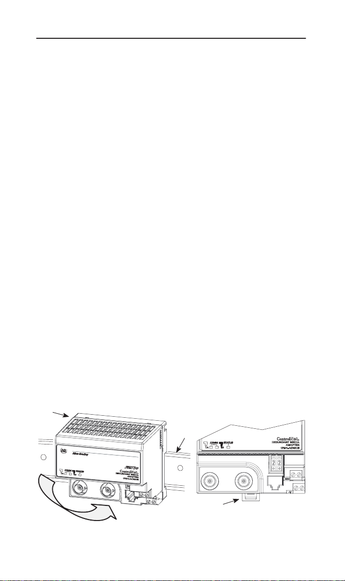
1. Position the ControlNet adapter module (A) on a 35 x 7.5mm DIN rail
(B) (A-B pt. no. 199-DR1; 46277-3; EN 50022) at a slight angle.
2. Hook the lip on the rear of the adapter (A) onto the top of the DIN rail
(B), and rotate the adapter module onto the rail.
3. Press the adapter module down onto the DIN rail until flush. Locking
tab (C) will snap into position and lock the adapter module to the DIN
rail.
4. If the adapter module does not lock in place, use a screwdriver or
similar device to move the locking tab down while pressing the
adapter module flush onto the DIN rail and release the locking tab to
lock the adapter module in place. If necessary, push up on the locking
tab to lock.
5. Connect the adapter wiring as shown under “Wiring” later in this
document.
ATTENTION: Make certain that the hook on the
terminal base is properly hooked into the adapter. Failure
!
6. Complete the adapter mounting as shown below.
to lock the hook into the adjacent base/adapter can result
in loss of communication on the backplane.
Publication
1794-5.18 – September 1996
Page 4
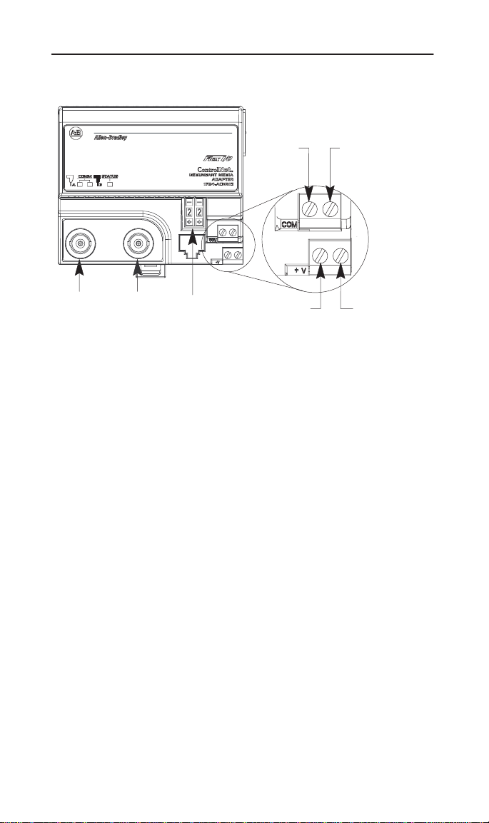
Wiring
FLEX I/O ControlNet Redundant Media Adapter4
C
AG
1. Connect the ControlNet network cable to connector, terminal A.
2. Connect the redundant ControlNet network cable to connector B.
3. Connect 24V common to the left side of the upper connector,
terminal C.
4. Connect +24V dc input to the left side of the lower connector,
terminal D.
5. Connections E and F are used to pass 24V dc power (F) and 24V
common (E) to the next module in the series (if required).
6. Set the network address using the 2-position thumbwheel switch G.
Valid settings range from 01 to 99. Press either the + or – buttons to
change the number.
B
D
E
F
Indicators
Publication
1794-5.18 – September 1996
Page 5

FLEX I/O ControlNet Redundant Media Adapter 5
Comm B
Comm A
Status Indicators Probable Cause
Comm A and Comm B Simultaneously
Off No
Red
Red/Grn – (flashing alternately) Adapter self-test
Red/Of
f – (flashing alternately)
power
, or reset
Adapter inoperative
Bad node configuration (duplicate address)
Comm A or Comm B (individually)
Off Channel disabled
Green
Flashing Grn/Off T
Flashing Red/Off
Flashing Red/Grn
Channel operational
emporary network errors
Cable fault, broken cable, redundancy warning
Bad network configuration
Status
Status Indicator
Off Channel disabled
Flashing Grn
Green On-line, link okay
Flashing Red
Red
1794-ACNR
I/O
Capacity
Specifications
On-line but not connected
Recoverable fault
Critical – adapter failure
8 modules
Publication
, connected
1794-5.18 – September 1996
Page 6

FLEX I/O ControlNet Redundant Media Adapter6
Power Supply
Input V
oltage Rating
Input Voltage Range
Communication Rate
Indicators
Flexbus Output Current
Isolation Voltage
Power Consumption
Power Dissipation
Thermal Dissipation
Environmental Conditions
Operational T
Storage T
emperature
emperature
Relative Humidity
Shock Operating
Non-operating
Vibration
ControlNet Cable
Power Conductors
Wire Size
Category
Specifications continued on next page
Note:
In order to comply with CE Low V
oltage
Directives, you must use a Safety Extra Low
V
oltage (SEL
V
oltage (PELV) power supply to power this
V) or a Protected Extra Low
adapter.
24V dc nominal
19.2V to 31.2V dc (includes 5% ac ripple)
5M Bits/s
Comm A – red/grn
Comm B – red/grn
I/O Status – red/grn
640mA maximum @ 5V dc
100% tested at 850V dc for 1s between user
power and flexbus
400mA maximum from external 24V supply
4.6W maximum @ 19.2V dc
15.7 BTU/hr @ 19.2V dc
0 to 55oC (32 to 131oF)
–40 to 85oC (–40 to 185oF)
5 to 95% noncondensing
30 g peak acceleration, 1
50 g peak acceleration, 1
T
ested 5 g @ 10–500Hz per IEC 68-2-6
1(+
1)ms pulse width
1(+
1)ms pulse width
Belden RG-6/U
12 gauge (4mm2) stranded maximum
3/64 inch (1.2mm) insulation max.
1
2
Publication
1794-5.18 – September 1996
Page 7

FLEX I/O ControlNet Redundant Media Adapter 7
Wiring T
erminal Screw T
Requirement
Agency Certification
(when product or packaging is
marked)
1 Use
this conductor category information for planning conductor routing. Refer to publication
1770-4.1, “Industrial Automation Wiring and Grounding Guidelines.”
orque
7-9 inch-pounds
•
CSA certified
• CSA Class I, Division 2
Groups A, B, C, D certified
•
UL listed
•
CE marked for all applicable directives
Mounting
Dimensions
Inches
(Millimeters)
3.2
(80)
3.4
(87)
A
=
DIN rail
B
= Secure DIN rail approximately every 200mm
3.7
(94)
1794-ACNR
3.4H x 3.7W x 2.7D
(87H x 94W x 69D)
B
2.0
(50)
1.2
(30)
A
Publication
1794-5.18 – September 1996
Page 8

FLEX I/O ControlNet Redundant Media Adapter8
With major offices worldwide.
World
Headquarters,
Allen-Bradley
1201 South Second Street,
Milwaukee, WI 53204 USA,
T
el: (1) 414 382-2000 Fax: (1) 414 382-4444
Publication 1794-5.18 – September 1996
Publication
,
1794-5.18 – September 1996
Copyright
1996 Allen-Bradley Company, Inc. Printed in USA
PN955117–39
 Loading...