

Page 1

FLEX I/O System with ControlLogix for SIL 2
Catalog Number Bulletin 1794
Reference Manual
Page 2
Important User Information
WARNING
IMPORTANT
ATTENTION
SHOCK HAZARD
BURN HAZARD
Solid state equipment has operational characteristics differing from those of electromechanical equipment. Safety Guidelines for the Application,
Installation and Maintenance of Solid State Controls (publication SGI-1.1
http://literature.rockwellautomation.com
) describes some important differences between solid state equipment and hard-wired electromechanical
devices. Because of this difference, and also because of the wide variety of uses for solid state equipment, all persons responsible for applying this
equipment must satisfy themselves that each intended application of this equipment is acceptable.
In no event will Rockwell Automation, Inc. be responsible or liable for indirect or consequential damages resulting from the use or application of this
equipment.
The examples and diagrams in this manual are included solely for illustrative purposes. Because of the many variables and requirements associated
with any particular installation, Rockwell Automation, Inc. cannot assume responsibility or liability for actual use based on the examples and
diagrams.
No patent liability is assumed by Rockwell Automation, Inc. with respect to use of information, circuits, equipment, or software described in this
manual.
Reproduction of the contents of this manual, in whole or in part, without written permission of Rockwell Automation, Inc., is prohibited.
Throughout this manual, when necessary, we use notes to make you aware of safety considerations.
available from your local Rockwell Automation sales office or online at
Identifies information about practices or circumstances that can cause an explosion in a hazardous environment, which may
lead to personal injury or death, property damage, or economic loss.
Identifies information that is critical for successful application and understanding of the product.
Identifies information about practices or circumstances that can lead to: personal injury or death, property damage, or
economic loss. Attentions help you identify a hazard, avoid a hazard, and recognize the consequence.
Labels may be on or inside the equipment, such as a drive or motor, to alert people that dangerous voltage may be present.
Labels may be on or inside the equipment, such as a drive or motor, to alert people that surfaces may reach dangerous
temperatures.
Allen-Bradley, Rockwell Automation, FLEX I/O, RSLinx, RSLogix 5000 and TechConnect are trademarks of Rockwell Automation, Inc.
Trademarks not belonging to Rockwell Automation are property of their respective companies.
Page 3

Preface
Introduction
Manual Set-Up
Table Preface.1
This application manual is intended to describe the FLEX I/O with ControlLogix
Control System components available from Rockwell Automation that are
suitable for use in SIL2 applications. Use this manual in conjunction with
publication 1756-RM001
Alternate architecture can be used in SIL2 applications if they are approved by
a certifying agency.
This manual is designed to make clear how the FLEX I/O with ControlLogix
Control System can be SIL2-certified. Table Preface.1 lists the information
available in each section.
Section: Title: Description:
Chapter 1 SIL Policy Introduction to the SIL policy and how that
policy relates to FLEX I/O with a ControlLogix
system.
Chapter 2 ControlLogix Communications Description of the ControlLogix communications
modules used in the SIL2-certified FLEX I/O
with ControlLogix system.
Chapter 3 FLEX I/O Modules Description of the FLEX I/O modules used in the
SIL2-certified FLEX I/O with ControlLogix
system.
Chapter 4 General Requirements for
Application Software
Application software requirements for using
ControlLogix and FLEX modules.
Chapter 5 Technical SIL2 Requirements
for the Application Program
Appendix A Failure Estimates Failure rates based on field returns.
Understanding Terminology
1 Publication 1794-RM001G-EN-P - December 2011
The following table defines acronyms used in this manual.
Table Preface.2 List of Acronyms Used Throughout the Safety Application Manual
Acronym: Full Term: Definition:
CIP Control and
Information
Protocol
DC Diagnostic
Coverage
EN European Norm. The official European Standard
GSV Get System Value A ladder logic output instruction that retrieves
Guidelines for application development in
RSLogix 5000 as they relate to SIL2.
A messaging protocol used by Logix5000™
systems. It is a native communications protocol
used on ControlNet™ communications networks,
among others.
The ratio of the detected failure rate to the total
failure rate.
specified controller status information and places
it in a destination tag.
Page 4

Preface 2
Table Preface.2 List of Acronyms Used Throughout the Safety Application Manual
Acronym: Full Term: Definition:
MTBF Mean Time
Average time between failure occurrences.
Between Failures
MTTR Mean Time to
Restoration
Average time needed to restore normal operation
after a failure has occurred.
PADT Programming and
Debugging Tool
RSLogix 5000 software used to program and
debug a SIL2-certified FLEX I/O with ControlLogix
application.
PC Personal
Computer
Computer used to interface with, and control, a
ControlLogix system via RSLogix 5000
programming software.
PFD Probability of
Failure on
The average probability of a system to fail to
perform its design function on demand.
Demand
PFH Probability of
Failure per Hour
The probability of a system to have a dangerous
failure occur per hour.
1oo1 One out of one A 1oo1 (one out of one) architecture consists of a
single channel where any dangerous failure leads
to a failure of the safety function.
1oo2 One out of two A 1oo2 (one out of two) architecture consists of
two channels connected in parallel such that
either channel can process the safety function.
Publication 1794-RM001G-EN-P - December 2011
Page 5

Chapter
SIL Policy
This chapter introduces you to the SIL policy and how the
ControlLogix/FLEX I/O system meets the requirements for SIL2
certification.
For information about: See page:
Introduction to SIL 1-1
SIL2 Certification 1-2
Proof Tests 1-3
SIL2-Certified FLEX I/O System Components 1-5
Hardware Designs and Firmware Functions 1-8
Hardware Designs and Firmware Functions 1-8
1
Introduction to SIL
Difference Between PFD and PFH 1-8
SIL Compliance Distribution and Weight 1-13
Response Times 1-13
Certain catalog numbers (listed in Table 1.1 on page 1-5) of the FLEX I/O with
ControlLogix system are type-approved and certified for use in SIL2
applications, according to IEC 61508. SIL requirements are based on the
standards current at the time of certification.
These requirements consist of mean time between failures (MTBF),
probability of failure, failure rates, diagnostic coverage and safe failure
fractions that fulfill SIL2 criteria. The results make the ControlLogix/FLEX
I/O system suitable up to, and including, SIL2. When the
ControlLogix/FLEX I/O system is in the maintenance or programming
mode, the user is responsible for maintaining a safe state.
For support in creation of programs, the PADT (Programming and
Debugging Tool) is required. The PADT for ControlLogix/FLEX I/O is
RSLogix 5000, per IEC 61131-3, and this Safety Reference Manual.
The TUV Rheinland has approved the ControlLogix/FLEX I/O system for
use in up to and including SIL 2 safety related applications in which the
de-energized state is considered to be the safe state. All of the examples related
to I/O included in this manual are based on achieving de-energization as the
safe state for typical Emergency Shutdown (ESD) Systems.
1 Publication 1794-RM001G-EN-P - December 2011
Page 6
1-2 SIL Policy
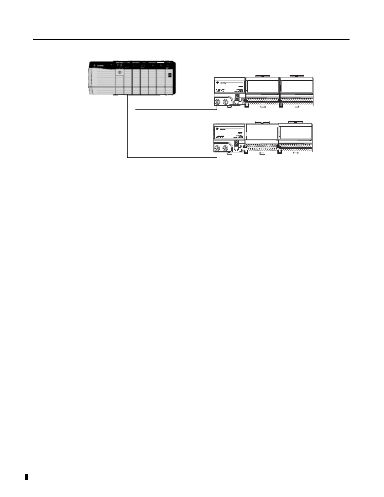
Plant-wide Ethernet/Serial
ControlNet
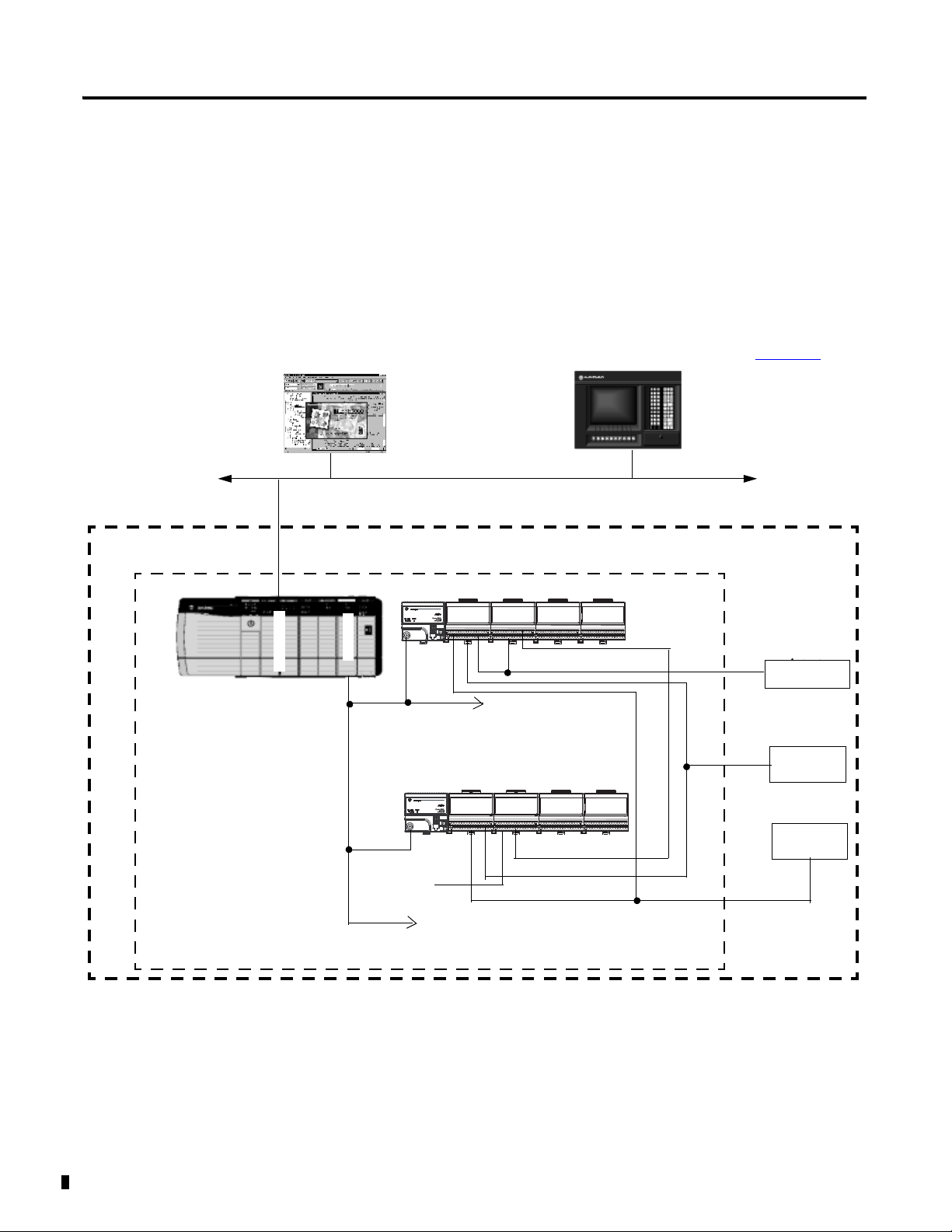
SIL2-certified ControlLogix components’ portion of the overall safety loop
Programming Software
For SIL applications, a programming
terminal is not normally connected.
HMI
For Diagnostics and Visualization (read-only access to controllers in the
safety loop). For more information, see publication 1756-RM001.
E
N
B
C
N
B
To other safety related
ControlLogix or FLEX I/O
remote I/O chassis
Overall Safety Loop
Actuator
Actuator
1794 FLEX I/O
Input
Device
DI1
DO2
DO1
DI2
ControlNet
Input
Device
To other safety related
ControlLogix or FLEX I/O
remote I/O chassis
See Figures 3.1 and 3.5 for details.
1
Note 1: Multiple 1756-CNB or -CNBR modules can be installed into the chassis as needed.
Other configurations are possible as long as they are SIL2 approved.
+V
SIL2 Certification
Figure 1.1 shows a typical SIL loop, including:
• the overall safety loop
• the ControlLogix/FLEX I/O portion of the overall safety loop
• how other devices (for example, HMI) connect to the loop, while
operating outside the loop
Figure 1.1
Note 2: Two adapters are required for meeting SIL2 as shown in the figure.
The adapters can be either ControlNet or Ethernet and must be from the list of approved products.
Publication 1794-RM001G-EN-P - December 2011
Page 7

SIL Policy 1-3
IMPORTANT
IMPORTANT
Important Note related to published PFDs.
• The user must choose the appropriate PFD depending
on combinations and the appropriate 1oo1 or 1oo2
configuration.
• Descrete and analog inputs must be used in a 1oo2
configuration for SIL 2.
• Adapters must be used in a 1oo2.
• Outputs may be 1oo2 in series or 1oo1 monitored by
an input with an external relay as a secondary device to
remove power.
• Some specialized inputs can only be wired to a single
sensor such as thermocuples and two 1oo1 PFDs must
be used for each.
• The total PFD for two 1oo1s is the sum of both.
The system user is responsible for:
Proof Tests
• the set-up, SIL rating and validation of any sensors or
actuators connected to the ControlLogix/FLEX I/O
control system.
• project management and functional testing.
programming the application software and the module
configuration according to the description in the
following chapters.
The SIL2 portion of the certified system excludes the
development tools and display/human machine interface
(HMI) devices; these tools and devices are not part of the
run time control loop.
IEC 61508 requires the user to perform various proof tests of the equipment
used in the system. Proof tests are performed at user-defined times (for
example, proof test intervals can be once a year, once every two years or
whatever timeframe is appropriate) and include some of the following tests:
• Testing of all fault routines to verify that process parameters are
monitored properly and the system reacts properly when a fault
condition arises.
• Testing of digital input or output channels to verify that they are not
stuck in the ON or OFF state.
Publication 1794-RM001G-EN-P - December 2011
Page 8

1-4 SIL Policy
IMPORTANT
• Calibration of analog input and output modules to verify that accurate
data is obtained from and used on the modules.
Users’ specific applications will determine the timeframe
for the proof test interval.
However, keep in mind that the Probability of Failure on
Demand (PFD) calculations listed in Table 1.2 on page 1-8
use a proof test interval of once per year. If the proof test
interval is changed, the information must be recalculated.
For more information on system proof tests, see Publication 1756-RM001
more information on the necessary I/O module, see Table 1.1.
. For
Publication 1794-RM001G-EN-P - December 2011
Page 9

SIL Policy 1-5
SIL2-Certified FLEX I/O
Table 1.1 lists the components available for use in a SIL2-certified FLEX I/O
system. For a list of ControlLogix SIL2 certified products, see publication
System Components
Table 1.1 FLEX I/O Components For Use in the SIL 2 System
Device Type: Catalog Number:
Adapter 1794-ACN15 ControlNet Single Media
1794-ACNR15 ControlNet Redundant Media
1794-ACNR15XT C 5.1, 5.2, 5.3,
(1)
Adapter
Adapter
1756-RM001
Description:
.
Firmware
Revision:
(2)
Series
C4.3
D 10.1, 10.2,
C4.3
D 10.1, 10.2,
(2) (3)
5.1, 5.2, 5.3,
5.x
10.3, 10.x
5.1, 5.2, 5.3,
5.x
10.3, 10.x
5.x
Related Documentation
with More Information on
Catalog Number:
Installation
Instructions:
1794-IN101 NA
1794-IN128
User Manual:
(4)
I/O Modules Digital
D 10.1, 10.2,
10.3, 10.x
1794-AENT 10/100Mb Ethernet
Communication Adapter
1794-AENTR A 1.011, 1.x 1794-IN131 1794-UM066
1794-AENTRXT
1794-IB16 16 Sink Input Module A NA 1794-IN093 NA
1794-IB10XOB6 10 Input/6 Output Module A NA 1794-IN083
1794-OB16 16 Source Output Module A NA 1794-IN094
1794-OB16P 16 Protected Output Module A NA 1794-IN094
1794-OB8EP 8 Protected Output Module A NA 1794-IN094
1794-OW8 Isolated Relay Output Module A NA 1794-IN019
1794-OB8EPXT 8 Protected Output Module A NA 1794-IN124
1794-IB16XT 16 Sink Input Module A NA
1794-OB16PXT 16 Protected Output Module A NA
1794-IB10XOB6XT 10 Input/6 Output Combo
Module
1794-OW8XT 8 Relay Output Module A NA 1794-IN019
B4.1
4.2, 4.x
ANA
1794-IN082
Publication 1794-RM001G-EN-P - December 2011
Page 10

1-6 SIL Policy
Table 1.1 FLEX I/O Components For Use in the SIL 2 System
Device Type: Catalog Number:
I/O Modules Analog
1794-IE8 8 Input Analog Module B NA 1794-IN100 1794-UM002
1794-IF4I 4 Isolated Input Analog
1794-IF2XOF2I 2 In/2 Out Isolated Combo
1794-OE4 4 Output Analog Module B NA 1794-IN100 1794-UM002
1794-OF4I 4 Isolated Output Analog
1794-IT8 Thermocouple Input Module A K, K.x 1794-IN021 1794-UM007
1794-IR8 RTD Input Module A K, K.x 1794-IN021 1794-UM004
1794-IRT8 TC/RTD Input Module B B, D, E, E.1,
1794-IJ2 2 Ch. Frequency Counter
(1)
Module
Module
Module
Module
Description:
Related Documentation
(4)
with More Information on
Catalog Number:
Series
(2)
Firmware
Revision:
(2) (3)
Installation
Instructions:
User Manual:
A F, G, H, I, I.x 1794-IN038 1794-UM008
A F, G, H, I, I.x 1794-IN039 1794-UM008
A F, G, H, I, I.x 1794-IN037 1794-UM008
1794-IN050 1794-UM012
E.x
A D 1794-IN049 1794-UM011
I/O Modules Analog
1794-IP4 4 Ch. Pulse Counter Module B 4, 4.x 1794-IN064 1794-UM016
1794-IE4XOE2XT 4 Input/2 Output Analog
B NA 1794-IN125 NA
Combo Module
1794-IE8XT 8 Input analog Module B NA
1794-OE4XT 4 Output Analog Module B NA
1794-IF2XOF2IXT 2 Input/2 Output Isolated
A I, I.x 1794-IN129
Analog Combo Module
1794-IF4IXT 4 Isolated Input Analog
A I, I.x
Module
1794-OF4IXT 4 Isolated Output Analog
A I, I.x
Module
1794-IF4ICFXT 4 Isolated Input Analog
A I, I.x 1794-IN130
Module
1794-IJ2XT 2 Ch. Frequency Counter
A E, E.x 1794-IN049
Module
1794-IRT8XT 8 TC/RTD Input Analog
B D, E, E.1, E.x 1794-IN050
Module
Publication 1794-RM001G-EN-P - December 2011
Page 11
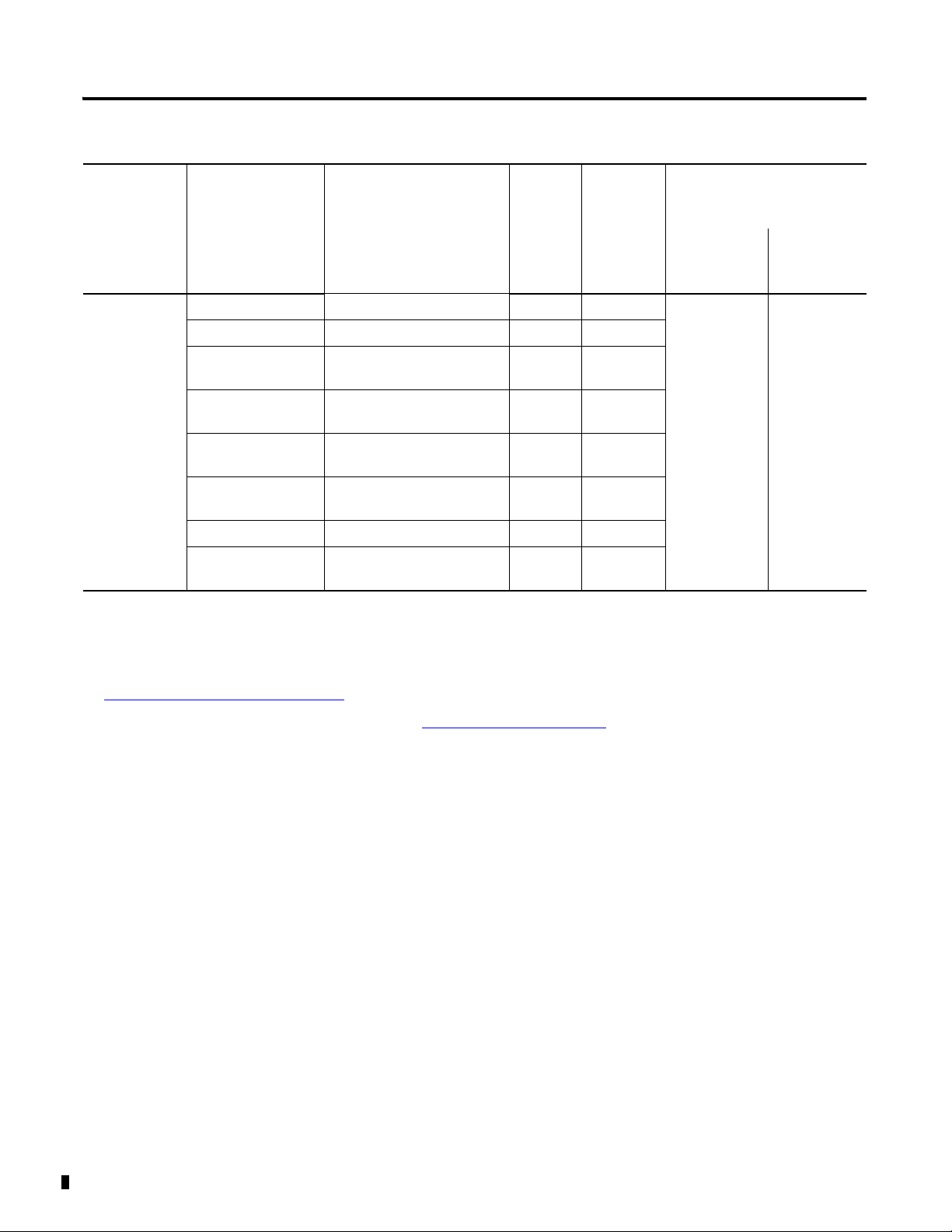
Table 1.1 FLEX I/O Components For Use in the SIL 2 System
SIL Policy 1-7
Related Documentation
with More Information on
Catalog Number:
Device Type: Catalog Number:
Terminal Base
Units
1794-TB3 3-Wire Terminal Base Unit A NA 1794-IN092 NA
1794-TB3S 3-Wire Terminal Base Unit A NA
1794-TB3T Temperature Terminal Base
Firmware
Revision:
(1)
Description:
Series
(2)
(2) (3)
ANA
Installation
Instructions:
User Manual:
Unit
1794-TB3TS Spring-clamp Temperature
ANA
Base Unit
1794-TB3G Cage-clamp Gen. Terminal
ANA
Base Unit
1794-TB3GS Spring-clamp Gen. Terminal
ANA
Base Unit
1794-TBN NEMA Terminal Base Unit A NA
1794-TBNF Fused NEMA Terminal Base
ANA
Unit
(1)
Certain catalog numbers have a K suffix. This indicates a conformally coated version of the product. These K versions have the same SIL2 certification as the non-K
versions.
(2)
The FW versions marked with extension .x (x can be 0 ... 99) are constitute to minor changes for enhancements. The test institute will be informed on any change.
(3)
Users must use these series and firmware revisions for their application to be SIL2 certified. Firmware revisions are available by visiting
http://support.rockwellautomation.com/ControlFlash/
(4)
These publications are available from Rockwell Automation by visiting http://literature.rockwellautomation.com.
(4)
Publication 1794-RM001G-EN-P - December 2011
Page 12

1-8 SIL Policy
Hardware Designs and Firmware Functions
Difference Between PFD and PFH
Diagnostic hardware designs and firmware functions designed into the
ControlLogix/FLEX I/O platform allow it to achieve at least SIL2
certification in a single-controller configuration. These diagnostic features are
incorporated into specific FLEX I/O components, such as the:
• adapter
• power supply
• I/O modules
• terminal base units
and are covered in subsequent sections. The ControlLogix/FLEX I/O
platform’s designs, features and characteristics make it one of the most
intelligent platforms.
Table 1.2 and Table 1.3 present values of the PFDs and PFHs for the specific
FLEX I/O products evaluated by TUV.
FLEX I/O uses the same PFD and PFH assumptions as stated in publication
1756-RM001
.
Table 1.2 FLEX I/O Product Probability of Failure on Demand (PFD) Calculations (T1 = 1 yr)
Catalog Number Description Mean Time
Between Failure
(1)
(MTBF)
1794-ACN15 ControlNet Single Media Adapter 8,223,684 1.22E-07 2.15E-06
1794-ACNR15 ControlNet Redundant Media Adapter 8,223,684 1.22E-07 2.15E-06
1794-AENT 10/100Mb Ethernet Communication Adapter 691,134 1.45E-06 2.76E-05
1794-AENTR 10/100Mb Ethernet Redundant Communication Adapter 1,268,070 7.89E-07 1.45E-05
1794-IB10XOB6 10 Input/6 Output Module 4,943,442 2.02E-07 3.60E-06
1794-IB16 16 Sink Input Module 4,105,090 2.44E-07 4.34E-06
1794-IE8 Analog Input Module 37,952,679 2.63E-08 4.64E-07
1794-IF2XOF2I Isolated Analog Input/Output Module 25,296,960 3.95E-08 6.97E-07
1794-IF4I Isolated Analog Input Module 11,746,343 8.51E-08 1.50E-06
1794-IJ2 Frequency Counter Module 2,418,321 4.14E-07 7.45E-06
1794-IP4 Pulse Counter Module 2,375,360 4.21E-07 7.58E-06
1794-IR8 RTD Input Module 6,191,655 1.62E-07 2.87E-06
1794-IRT8 TC/RTD/mV Input Module 1,182,438 8.46E-07 1.56E-05
1794-IT8 Thermocouple Input Module 1,564,324 6.39E-07 1.17E-05
1794-OB16 16 Source Output Module 1,883,594 5.31E-07 9.62E-06
1794-OB16P Protected Output Module 2,135,280 4.68E-07 8.46E-06
(3)
λ
Calculated PFD
1oo2 architecture
Publication 1794-RM001G-EN-P - December 2011
Page 13

Table 1.2 FLEX I/O Product Probability of Failure on Demand (PFD) Calculations (T1 = 1 yr)
SIL Policy 1-9
Catalog Number Description Mean Time
Between Failure
(1)
(MTBF)
1794-OB8EP Protected Output Module
2,389,669
(2)
(3)
λ
4.18E-07 7.54E-06
Calculated PFD
1oo2 architecture
1794-OE4 Analog Output Module 23,807,086 4.20E-08 7.41E-07
1794-OF4I Isolated Analog Output Module 7,191,128 1.39E-07 2.47E-06
1794-OW8 Relay Output Module 14,766,876 6.77E-08 1.20E-06
1794-TB3 Terminal Base Units
21,128,346
(2)
4.73E-08 8.35E-07
1794-TB3G Generic Terminal Base Units 27,320,800 3.66E-08 6.45E-07
1794-TB3GS Generic Terminal Base Units 46,425,600 2.15E-08 3.79E-07
1794-TB3S Terminal Base Unit
1794-TB3T Temperature Terminal Base Units
1794-TB3TS Temperature Terminal Base Units
71,433,747
73,096,226
75,763,399
(2)
(2)
(2)
1.40E-08 2.46E-07
1.37E-08 2.41E-07
1.32E-08 2.32E-07
1794-TBN Terminal Base Units 75,716,615 1.32E-08 2.32E-07
1794-TBNF Fused Terminal Base Units
4,812,320
(2)
2.08E-07 3.70E-06
1794-ACNR15XT ControlNet Redundant Media Adapter 8,223,684 1.22E-07 2.15E-06
1794-AENTRXT 10/100Mb Ethernet Redundant Communication Adapter 1,268,070 7.89E-07 1.45E-05
1794-OB8EPXT 8 Protected Output Module 14,771,049 6.77E-08 1.20E-06
1794-IB16XT 16 Sink Input Module 35,587,189 2.81E-08 4.95E-07
1794-OB16PXT 16 Protected Output Module 26,709,401 3.74E-08 6.60E-07
1794-IB10XOB6XT 10 Input/6 Output Combo Module 22,202,487 4.50E-08 7.94E-07
1794-OW8XT 8 Relay Output Module 18,518,519 5.40E-08 9.53E-07
1794-IE4XOE2XT 4 Input/2 Output Analog Combo Module 11,800,802 8.47E-08 1.50E-06
1794-IE8XT 8 Input analog Module 14,041,000 7.12E-08 1.26E-06
1794-OE4XT 4 Output Analog Module 11,381,744 8.79E-08 1.55E-06
1794-IF2XOF2IXT 2 Input/2 Output Isolated Analog Combo Module 6,317,918 1.58E-07 2.81E-06
1794-IF4IXT 4 Isolated Input Analog Module 7,297,140 1.37E-07 2.43E-06
1794-IF4ICFXT 4 Isolated Input Analog Module 7,297,140 1.37E-07 2.43E-06
1794-OF4IXT 4 Isolated Output Analog Module 5,493,902 1.82E-07 3.24E-06
1794-IJ2XT 2 Ch. Frequency Counter Module 11,714,128 8.54E-08 1.51E-06
1794-IRT8XT 8 TC/RTD Input Analog Module 8,204,792 1.22E-07 2.16E-06
(1)
MTBF measured in hours.
(2)
Calculated using field-based values for components
(3)
λ = Failure Rate = 1/MTBF
Publication 1794-RM001G-EN-P - December 2011
Page 14

1-10 SIL Policy
Table 1.3 FLEX I/O Product Probability of Undetected Dangerous Failure per Hour (PFH) Calculations (T1 = 1 yr)
Catalog Number Description Mean Time
Between Failure
(1)
(MTBF)
(3)
λ
Calculated PFH
1oo2 architecture
1794-ACN15 ControlNet Single Media Adapter 8,223,684 1.22E-07 8.64E-10
1794-ACNR15 ControlNet Redundant Media Adapter 8,223,684 1.22E-07 8.64E-10
1794-AENT 10/100Mb Ethernet Communication Adapter 691,134 1.45E-06 1.19E-08
1794-AENTR 10/100Mb Ethernet Redundant Communication Adapter
1,268,070
(2)
7.89E-07 6.05E-09
1794-IB10XOB6 10 Input/6 Output Module 4,943,442 2.02E-07 1.45E-09
1794-IB16 16 Sink Input Module 4,105,090 2.44E-07 1.76E-09
1794-IE8 Analog Input Module 37,952,679 2.63E-08 1.85E-10
1794-IF2XOF2I Isolated Analog Input/Output Module 25,296,960 3.95E-08 2.78E-10
1794-IF4I Isolated Analog Input Module 11,746,343 8.51E-08 6.02E-10
1794-IJ2 Frequency Counter Module 2,418,321 4.14E-07 3.04E-09
1794-IP4 Pulse Counter Module 2,375,360 4.21E-07 3.10E-09
1794-IR8 RTD Input Module 6,191,655 1.62E-07 1.15E-09
1794-IRT8 TC/RTD/mV Input Module 1,182,438 8.46E-07 6.53E-09
1794-IT8 Thermocouple Input Module 1,564,324 6.39E-07 4.82E-09
1794-OB16 16 Source Output Module 1,883,594 5.31E-07 3.96E-09
1794-OB16P Protected Output Module 2,135,280 4.68E-07 3.47E-09
1794-OB8EP Protected Output Module
2,389,669
(2)
4.18E-07 3.08E-09
1794-OE4 Analog Output Module 23,807,086 4.20E-08 2.96E-10
1794-OF4I Isolated Analog Output Module 7,191,128 1.39E-07 9.90E-10
1794-OW8 Relay Output Module 14,766,876 6.77E-08 4.78E-10
1794-TB3 Terminal Base Units
21,128,346
(2)
4.73E-08 3.33E-10
1794-TB3G Generic Terminal Base Units 27,320,800 3.66E-08 2.57E-10
1794-TB3GS Generic Terminal Base Units 46,425,600 2.15E-08 1.51E-10
1794-TB3S Terminal Base Unit
1794-TB3T Temperature Terminal Base Units
1794-TB3TS Temperature Terminal Base Units
71,433,747
73,096,226
75,763,399
(2)
(2)
(2)
1.40E-08 9.82E-11
1.37E-08 9.59E11
1.32E-08 9.25E-11
1794-TBN Terminal Base Units 75,716,615 1.32E-08 9.26E-11
1794-TBNF Fused Terminal Base Units
4,812,320
(2)
2.08E-07 1.49E-09
1794-ACNR15XT ControlNet Redundant Media Adapte 8,223,684 1.22E-07 8.64E-10
1794-AENTRXT 10/100Mb Ethernet Redundant Communication Adapter
1,268,070
(2)
7.89E-07 6.05E-09
1794-OB8EPXT 8 Protected Output Module 14,771,049 6.77E-08 4.78E-10
1794-IB16XT 16 Sink Input Module 35,587,189 2.81E-08 1.97E-10
1794-OB16PXT 16 Protected Output Module 26,709,401 3.74E-08 2.63E-10
1794-IB10XOB6XT 10 Input/6 Output Combo Module 22,202,487 4.50E-08 3.17E-10
1794-OW8XT 8 Relay Output Module 18,518,519 5.40E-08 3.80E-10
Publication 1794-RM001G-EN-P - December 2011
Page 15
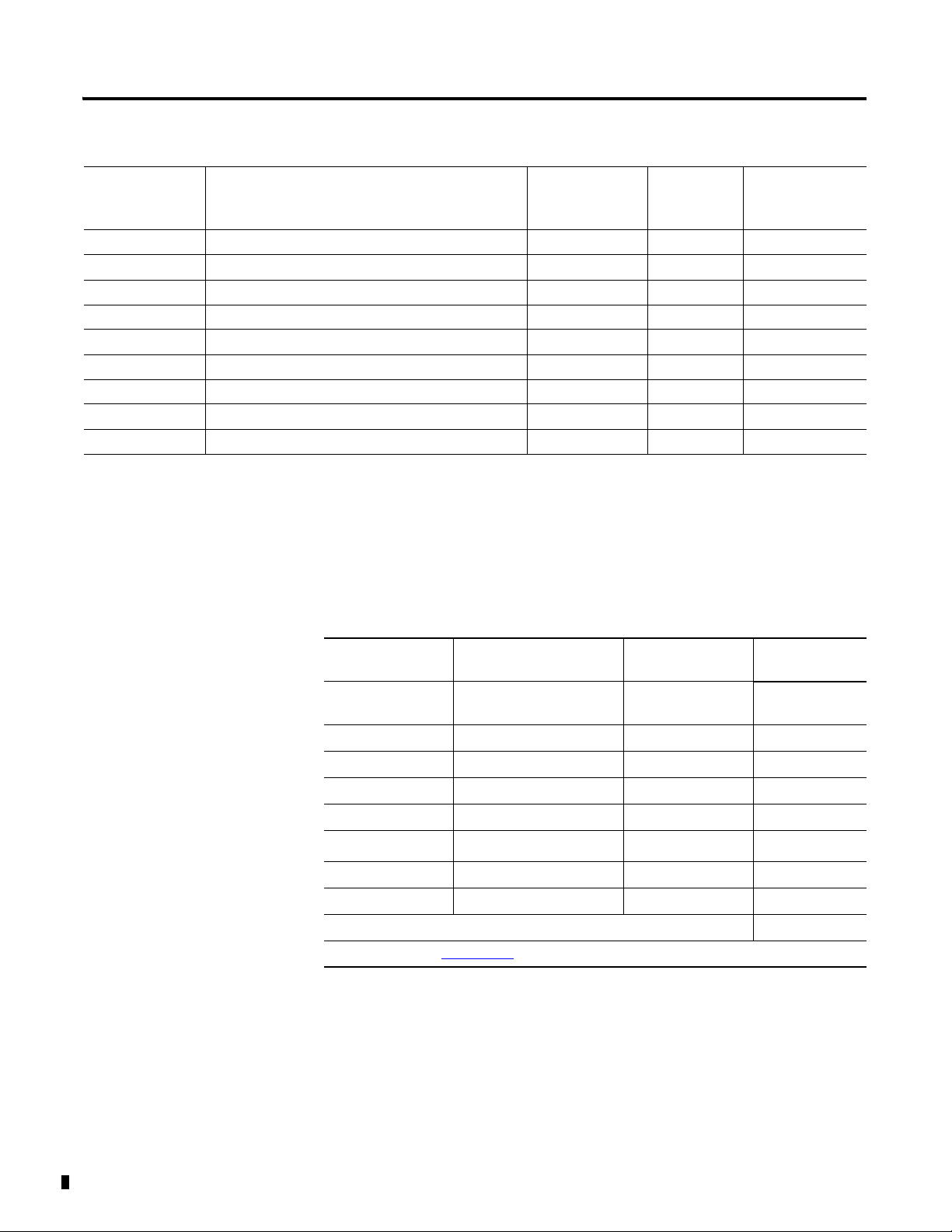
Table 1.3 FLEX I/O Product Probability of Undetected Dangerous Failure per Hour (PFH) Calculations (T1 = 1 yr)
SIL Policy 1-11
Catalog Number Description Mean Time
Between Failure
(1)
(MTBF)
(3)
λ
Calculated PFH
1oo2 architecture
1794-IE4XOE2XT 4 Input/2 Output Analog Combo Module 11,800,802 8.47E-08 5.99E-10
1794-IE8XT 8 Input analog Module 14,041,000 7.12E-08 5.03E-10
1794-OE4XT 4 Output Analog Module 11,381,744 8.79E-08 6.22E-10
1794-IF2XOF2IXT 2 Input/2 Output Isolated Analog Combo Module 6,317,918 1.58E-07 1.13E-09
1794-IF4IXT 4 Isolated Input Analog Module 7,297,140 1.37E-07 9.75E-10
1794-IF4ICFXT 4 Isolated Input Analog Module 7,297,140 1.37E-07 9.75E-10
1794-OF4IXT 4 Isolated Output Analog Module 5,493,902 1.82E-07 1.30E-09
1794-IJ2XT 2 Ch. Frequency Counter Module 11,714,128 8.54E-08 6.04E-10
1794-IRT8XT 8 TC/RTD Input Analog Module 8,204,792 1.22E-07 8.66E-10
(1)
MTBF measured in hours.
(2)
Calculated using field-based values for components
(3)
λ = Failure Rate = 1/MTBF
Table 1.4 shows an example of a PFD calculation for a safety loop involving
two DC input modules used in a 1oo2 configuration and a DC output module.
Table 1.4
Catalog Number: Description: MTBF: Calculated
1oo2 PFD:
1794-ACNR15 ControlNet Dual Media
3,259,605 1.56E-06
Adapter 1.5
1794-IB16 24V DC Input Module 6,409,846 4.34E-06
1794-IB16 24V DC Input Module 6,409,846 4.34E-06
1794-OB16 24V DC Output Module 4,284,857 9.62E-06
1794-OW8 Relay Output Module 1,312,973 1.20E-06
1756-L63B
1
ControlLogix Controller 2,460,065 2.33E-04
1756-CNB ControlNet Bridge Module 3,596,087 1.15E-04
1756-CNB ControlNet Bridge Module 3,596,087 1.15E-04
Total PFD calculation for a safety loop consisting of these products: 3.70E-04
1 See Publication 1756-RM001
for more information.
Publication 1794-RM001G-EN-P - December 2011
Page 16
1-12 SIL Policy
B
B
1794-OB16
1794-IB16
1794-TB3 (1)
1794-TB3 (2)
1794-ACNR15 (1)
1794-ACNR15 (2)
1794-IB16
1794-OW8
1756-CNB
1756-L63B
ControlNet
ControlNet
1756-CNB
Publication 1794-RM001G-EN-P - December 2011
Page 17

SIL Policy 1-13
SIL Compliance Distribution and Weight
Response Times
The programmable controller may conservatively be assumed to contribute
10% of the reliability burden. A SIL 2 system may need to incorporate multiple
inputs for critical sensors and input devices, as well as dual outputs connected
in series to dual actuators dependent on SIL assessments for the safety related
system.
The response time of the system is defined as the amount of time it takes for a
change in an input condition to be recognized and processed by the
controller’s ladder logic program, and then to initiate the appropriate output
signal to an actuator. The system response time is the sum of the following:
• input hardware delays
• input filtering
• I/O and communication module RPI settings
• controller program scan times
• output module propagation delays
See Table 1.1 for associated module information.
Each of the times listed above is variably dependent on factors such as the type
of I/O module and instructions used in the ladder program. For examples of
how to perform these calculations, see publication 1756-RM001
.
Publication 1794-RM001G-EN-P - December 2011
Page 18

1-14 SIL Policy
Notes:
Publication 1794-RM001G-EN-P - December 2011
Page 19

Chapter
2
ControlLogix Communications
This chapter discusses the communication modules used in a ControlLogix
SIL2 system.
For information about: See page:
ControlNet Bridge Module 2-1
EtherNet/IP Bridge Module 2-1
ControlNet Bridge Module
Related Communications Modules
Documentation
The ControlNet bridge modules (1756-CNB & 1756-CNBR) provide for the
communications between ControlLogix and FLEX I/O system.
2-3
ControlNet Cabling
For remote racks, 802.3 compliant shielded or unshielded twisted pair cable is
required for EtherNet/IP. Although it is not a requirement to use redundant
media with the 1756-CNBR, it does provide higher system availability.
Redundant media is not required for SIL2 operation.
ControlNet Module Diagnostic Coverage
All communications over the passive ControlNet media occur via CIP, which
guarantees delivery of the data. All modules independently verify proper
transmission of the data.
EtherNet/IP Bridge Module
1 Publication 1794-RM001G-EN-P - December 2011
The EtherNet/IP bridge modules (1756-ENBT, 1756-EN2T, 1756-EN2TR,
and 1756-EN2TXT) provide for the communications between ControlLogix
and FLEX I/O system.
Page 20
2-2 ControlLogix Communications
EtherNet/IP Cabling
802.3 compliant shielded or unshielded twisted pair cable is required for
EtherNet/IP.
EtherNet/IP Module Diagnostic Coverage
Communications over 10/100 MbpsNet media occur via CIP, which
guarantees delivery of the data. All modules independently verify proper
transmission of the data.
Module Fault Reporting for any FLEX I/O Module
To monitor the connection status for this type of connection, use a Get
System Value (GSV) and an examination of MODULE objects’ "Entry Status"
attribute for a running connection.
An example of how this might be done is shown in Figure 2.1. This method,
or something similiar, must be used to interrogate the health of each I/O
module in the system.
Figure 2.1 Example of Checking a Module’s Health in Ladder Logic
GSV
Obtain MODULE
Object’s Entry Status
NEQ
Check Entry Status to
make sure module is
running
AND
Mask Off Lower 12
Bits of Value
Fault
For more information on the GSV instruction, monitor the SlotStatusBits for
the Input tag of the associated adapter. The lower 8 bits of this tag correspond
to the associated slot. For example, the tag "Node3:I.SlotlStatusBits" is defined
as follows:
Publication 1794-RM001G-EN-P - December 2011
NODE3 - This is the name given to the associated 1794-AVNR15.
I = This indicates the Input file.
Page 21

ControlLogix Communications 2-3
Module
0
Module
1
Module
2
Module
3
Module
4
Module
5
Module
6
Module
7
SlotStatusBits - This is a 32 bit value. The lower 8 bits of this value are defined
as follows for FLEX I/O:
Related Communications Modules Documentation
For more information on ControlLogix communications modules, see the
following Rockwell Automation publications listed in Table 2.1:
Table 2.1
Catalog
Number: Description:
1756-CNB ControlNet Communication
Module
1756-CNBR Redundant ControlNet
Communication Module
Installation
Instructions:
1756-IN571
User Manual:
CNET-UM001
These publications are available from Rockwell Automation at:
http://literature.rockwellautomation.com
.
Publication 1794-RM001G-EN-P - December 2011
Page 22

2-4 ControlLogix Communications
Publication 1794-RM001G-EN-P - December 2011
Page 23

Chapter
FLEX I/O Modules
This chapter discusses the FLEX I/O modules that are SIL2 certified.
For information about: See page:
Overview of FLEX I/O Modules 3-1
Using Digital Input Modules 3-2
Wiring FLEX I/O Digital Input Modules 3-3
General Considerations when using Any FLEX
I/O Digital Output Module
Wiring FLEX I/O Digital Output Modules 3-5
Using Analog Input Modules 3-7
3-4
3
Overview of FLEX I/O Modules
Wiring FLEX I/O Analog Input Modules 3-9
Checklist for SIL Inputs 3-18
Checklist for SIL Outputs 3-19
In the most basic description, there are two types of SIL2-certified FLEX I/O
modules:
• Digital I/O modules
• Analog I/O modules
With each type, however, there are differences between specific modules.
Because the differences propagate to varying levels in each module type, a
graphical representation can best provide an overview of the many
SIL2-certified FLEX I/O modules.
FLEX I/O modules are designed with inherent features that assist them in
complying with the requirements of the 61508 Standard. For example, the
modules all have a common backplane interface, execute power-up and
runtime diagnostics, and offer electronic keying.
Table 1.1 lists the FLEX I/O modules initially submitted for SIL2
certification.
1 Publication 1794-RM001G-EN-P - December 2011
Page 24

3-2 FLEX I/O Modules
Using Digital Input Modules
General Considerations when using Any FLEX I/O Digital Input Module
Regardless of the type of FLEX I/O input module used, there are a number of
general application considerations that users must follow when applying these
modules in a SIL2 application:
• Proof Tests - Periodically (for example, once every several years) a
System Validation test must be performed. Manually, or automatically,
test inputs to make sure that all inputs are operational and not stuck in
the ON or OFF state. Inputs must be cycled from ON to OFF or OFF
to ON. .
• Wire sensors to separate input points on two separate modules that are
on different ControlNet nodes.
• Configuration parameters (for example, RPI, filter values) must be
identical between the two modules.
• The same controller must own both modules.
• Monitor the ControlNet status bits for the associated module and
ensure that appropriate action is invoked via the application logic by
these status bits.
Publication 1794-RM001G-EN-P - December 2011
Page 25

FLEX I/O Modules 3-3
Input 1 Input 2
Input
COM
+24V
12 3 45 67 891011121314150
24VDC SINK INPUT
1794-IB16
12 3 45 67 891011121314150
24VDC SINK INPUT
1794-IB16
12 3 45 67 891011121314150
24VDC SINK INPUT
1794-IB16
12 3 45 67 891011121314150
24VDC SINK INPUT
1794-IB16
Input
COM
+24V
Input 1 Input 2
SIL2 SENSOR
SENSOR
SENSOR
+24V dc
Optional relay contact
to switch line voltage
for periodic automated
testing
43366
One-Sensor Wiring Example
Two-Sensor Wiring Example
43366
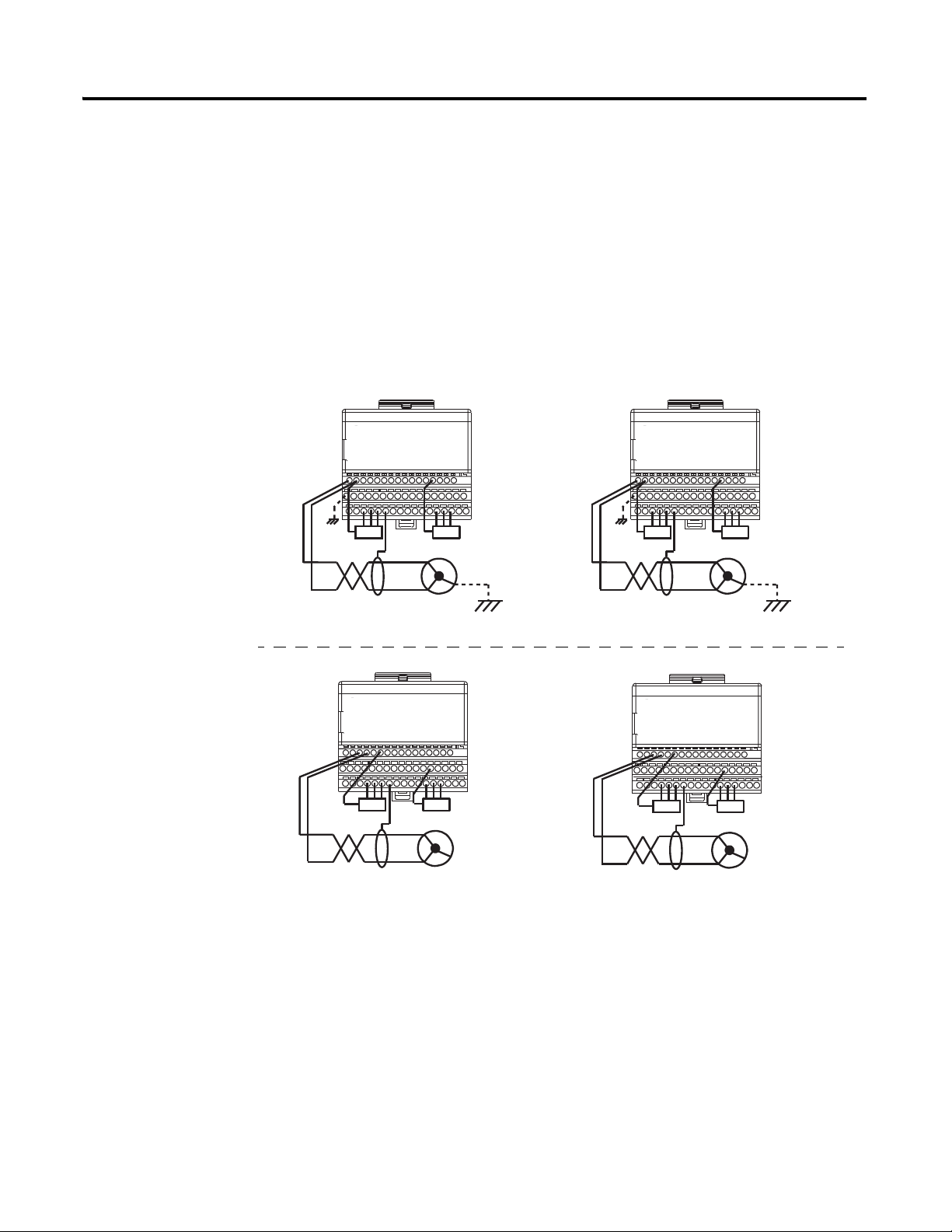
Note 1: Both sensors are monitoring the same safety application.
1
1
Input BInput A
Actuator
Input BInput A
Input BInput A
Tim er
Timer preset in milliseconds to
compensate for filter time and
hardware delay differences.
Fault
Timer Done
Alarm to Operator
Fault
Wiring FLEX I/O Digital Input Modules
The wiring diagrams in Figure 3.1 show two methods of wiring the digital
input Module. In either case, users must determine whether the use of 1 or 2
sensors is appropriate to fulfill SIL2 requirements.
Figure 3.1 ControlLogix Digital Input Module Wiring
Application logic can compare input values or states for concurrence.
Figure 3.2
The user program must also contain rungs to annunciate a fault in the event of
a sustained miscompare between two points.
Figure 3.3
Publication 1794-RM001G-EN-P - December 2011
Page 26

3-4 FLEX I/O Modules
The control, diagnostics and alarming functions must be performed in
sequence. For more information on faults, see publication 1756-RM001
.
General Considerations when using Any FLEX I/O Digital Output Module
Regardless of the type of FLEX I/O output module used, there are a number
of general application considerations that you must follow when applying
these modules in a SIL2 application:
• Proof Tests - Periodically (for example, once every several years) a
System Validation test must be performed. Manually, or automatically,
test outputs to make sure that all outputs are operational and not stuck
in the ON or OFF state. Outputs must be cycled from ON to OFF or
OFF to ON. For additional information, refer to publication
1756-RM001
.
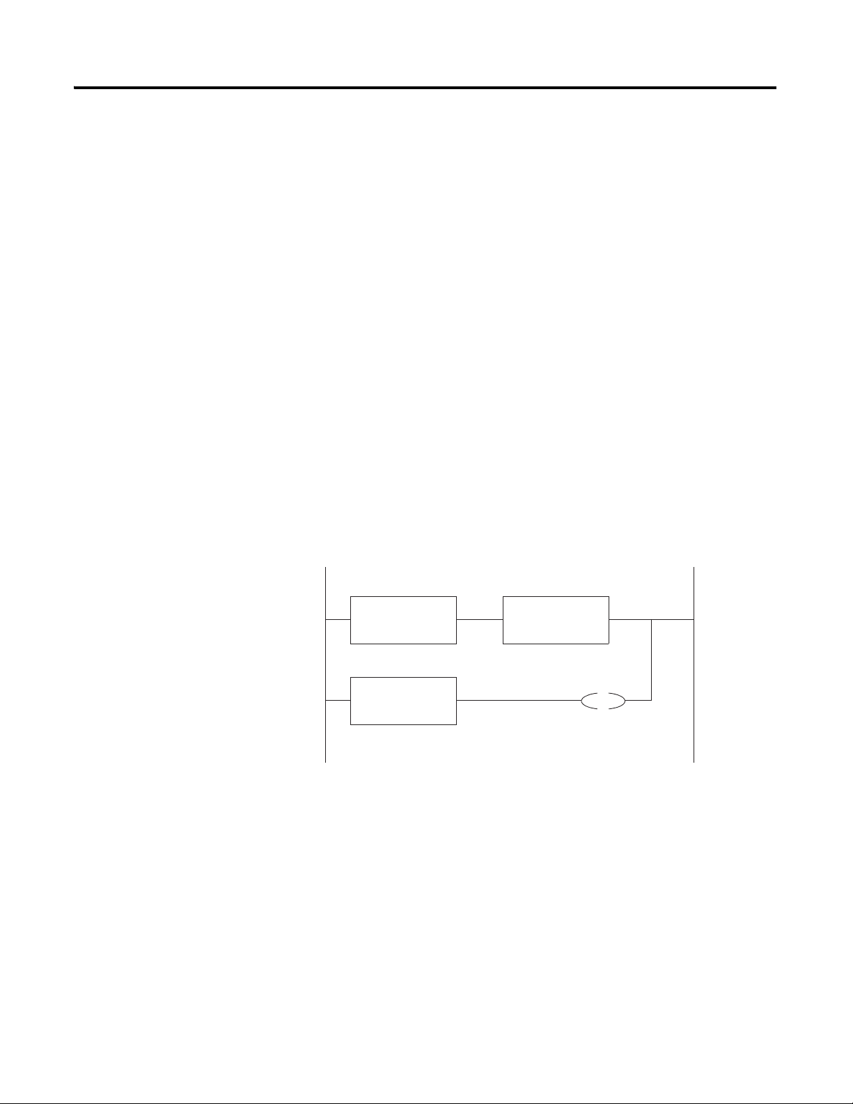
Figure 3.4
Application Logic
Output Bit
Output Bit
Timer done
Fault
Monitoring Input
Monitoring Input
Output Fault
Actuator
Tim er
Fault
Alarm to Operator
The control, diagnostics and alarming functions must be performed in
sequence..
• Use of external Relays to disconnect Module Power if Output
De-energization is Critical: To make sure outputs will de-energize,
users must wire an external method that can remove power from the
actuator if a short or other fault is detected.
Publication 1794-RM001G-EN-P - December 2011
• Test outputs at specific times to make sure they are operating
properly. The method and frequency of testing is determined by the
type of module.
Page 27
FLEX I/O Modules 3-5
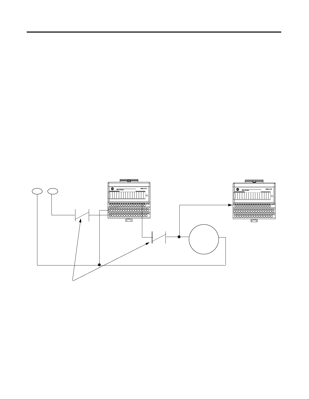
12 345 67 891011121314150
24VDC SOURCE OUTPUT
1794-OB16
1 2 3 4 5 6 7 8 91011121314150
24VDC SINK INPUT
1794-IB16
Standard Digital
Output Module
43363
Standard Digital
Input Module
+24V
COM
Output
Actuator
Install a relay in position A or B. This relay is controlled by another
output in the ControlLogix/FLEX I/O system. If a short circuit or fault
occurs on output modules, the relay can disconnect power to the
modules. An isolated relay output module (1794-OW8) can be used for
this purpose when it is connected to a different 1794-ACN15 or
-ACNR15 ControlNet Adapter module.
Wire output point
to input point to
verify the correct
state of the output
COM
24V dc
A
B
Note: Other configurations are possible as long they are
SIL2 approved.
• Monitor the ControlNet status bits for the associated module and
ensure that appropriate action is invoked via the application logic by
these status bits.
Wiring FLEX I/O Digital Output Modules
Standard Digital Output Modules
When using standard output modules, users must wire an output to an
actuator and then back to an input to monitor the output’s performance.
In addition to following the General Considerations when using Any FLEX
I/O Digital Output Module on page 3-4, the user must wire each standard
output to a corresponding input to validate that the output is following its
commanded state.
Figure 3.5 ControlLogix/FLEX I/O Standard Output Module Wiring
Application logic must be written to generate a fault in the event of a
miscompare between the requested state of an output (echo) and the actual
output state monitored by an input channel (see Figure 3.4).
The control, diagnostics and alarming functions must be performed in
sequence.
Publication 1794-RM001G-EN-P - December 2011
Page 28

3-6 FLEX I/O Modules
1 2 3 4 5 67 8910 11121314150
24VDC SINK INPUT
1794-IB16
1 2 3 4 5 67 8910 11121314150
24VDC SOURCE OUTPUT
1794-OB16
1 2 3 4 5 67 8910 11121314150
24VDC SOURCE OUTPUT
1794-OB16
Isolated Relay
Output Module
43364
Standard Digital
Input Module
Standard Digital
Output Module
+24V
COM
Wire output point
to input point to
verify the correct
state of the output
Output
Output
Actuator
+24V
COM
Note 1: An external relay can be replaced with an isolated
relay module which is mounted in another FLEX I/O rail.
Users can also wire a standard digital output module in series with an isolated
relay output module in series with a critical actuator. In the event that a failure
is detected, the output from both output modules must be set to OFF to
guarantee the Output Loads de-energize. This is shown in Figure 3.6.
Figure 3.6 ControlLogix/FLEX I/O Standard Output Module Wiring With an Isolated
Relay Module
Publication 1794-RM001G-EN-P - December 2011
Page 29

FLEX I/O Modules 3-7
Using Analog Input Modules
General Considerations when using Any FLEX I/O Analog Input Module
There are a number of general application considerations that you must follow
when applying these modules in a SIL2 application:
• Proof Tests - Periodically (for example, once every several years) a
System Validation test must be performed. Manually, or automatically,
test inputs to make sure that all inputs are operational. Field signal levels
should be varied over the full operating range to make sure that the
corresponding channel data varies accordingly. For additional
information, refer to publication 1756-RM001
• Calibrate Inputs Periodically, As Necessary: FLEX I/O modules
ship from the factory with a highly accurate level of calibration.
However, because each application is different, users are responsible for
making sure their FLEX I/O modules are properly calibrated for their
specific application.
Users can employ tests in application program logic to determine when
a module requires recalibration. For example, to determine whether an
input module needs to be recalibrated, a user can determine a tolerance
band of accuracy for a specific application. The user can then measure
input values on multiple channels and compare those values to
acceptable values within the tolerance band. Based on the differences in
the comparison, the user could then determine whether recalibration is
necessary.
.
Calibration (and subsequent recalibration) is not a safety issue.
However, we recommend that each analog input be calibrated at least
every 3 years to verify the accuracy of the input signal and avoid
nuisance application shutdowns.
• Compare Analog Input Data and Annunciate Miscompares: When
wiring sensors to two inputs channels, the values from those channels
must be compared to each other for concurrence within an acceptable
range for the application before actuating an output. Any miscompare
between the two inputs outside the programmed acceptable range must
be annunciated as a fault.
In Figure 3.7, a user-defined percentage of acceptable deviation (that is,
tolerance) is applied to the configured input range of the analog inputs
(that is, range) and the result is stored (that is, delta). This delta value is
then added to and subtracted from one of the input channels; the results
define an acceptable High and Low limit of deviation. The second input
channel is then compared to these limits to determine if the input are
working properly.
Publication 1794-RM001G-EN-P - December 2011
Page 30

3-8 FLEX I/O Modules
Timer done
Tim er
Inputs Faulted
Alarm to Operator
Inputs OK
SUB
Delta
Input 1
Low Limit
ADD
Delta
Input 1
High Limit
MULT
Range
Tole rance %
Delta
Inputs Faulted
LIM
Low Limit
Input 2
High Limit
Inputs OK
The input’s OK bit preconditions a Timer run that is preset to
accommodate an acceptable fault response time and any communication
filtering lags in the system. If the inputs miscompare for longer than the
preset value, a fault is registered with a corresponding alarm.
Figure 3.7
The control, diagnostics and alarming functions must be performed in
sequence.
• Configuration parameters (for example, RPI, filter values) must be
identical between the two modules.
• The same controller must own both modules.
• Monitor the ControlNet status bits for the associated module and
ensure that appropriate action is invoked via the application logic by
these status bits.
• Wire sensors to separate input channels on two separate modules that
are on different ControlNet nodes.
Publication 1794-RM001G-EN-P - December 2011
Page 31

FLEX I/O Modules 3-9
Input 1 Input 2
Input
COM
+24V
Input
COM
+24V
Input 1 Input 2
SIL2 SENSOR
SENSOR
43366A
One-Sensor Wiring Example
Two-Sensor Wiring Example
SENSOR
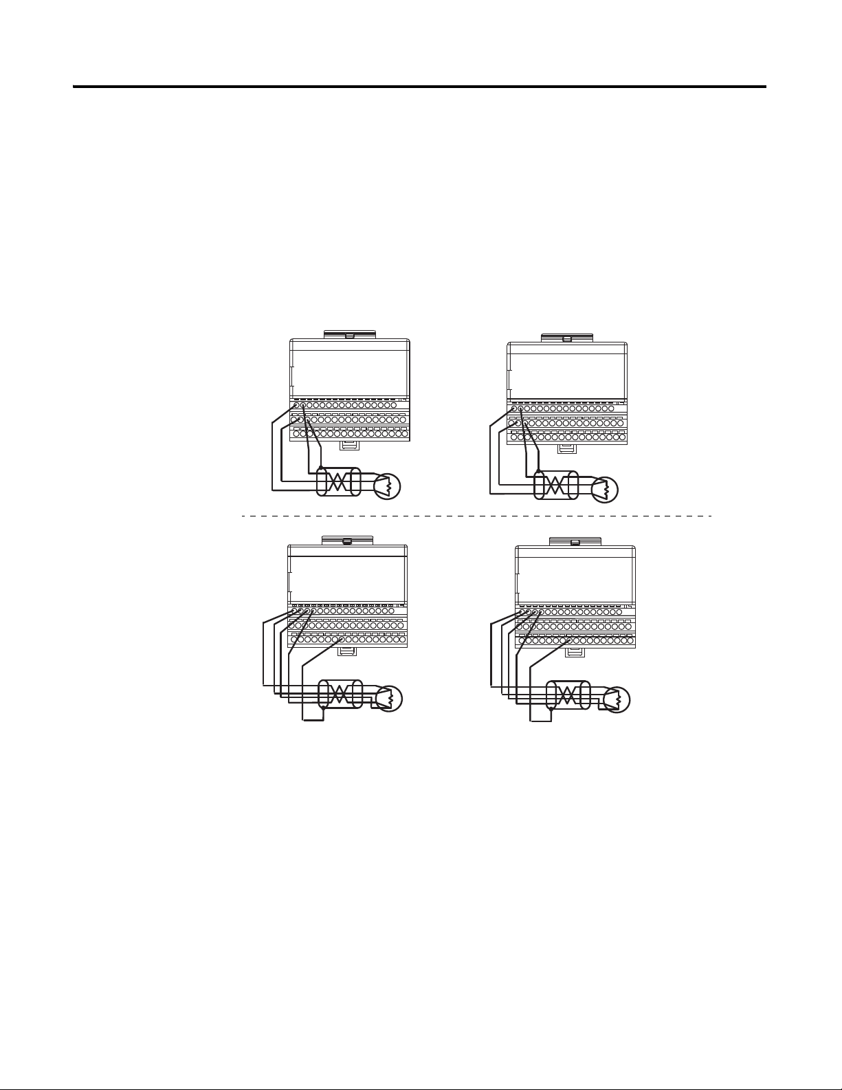
Note 1: Both sensors are monitoring the same safety application.
1
1
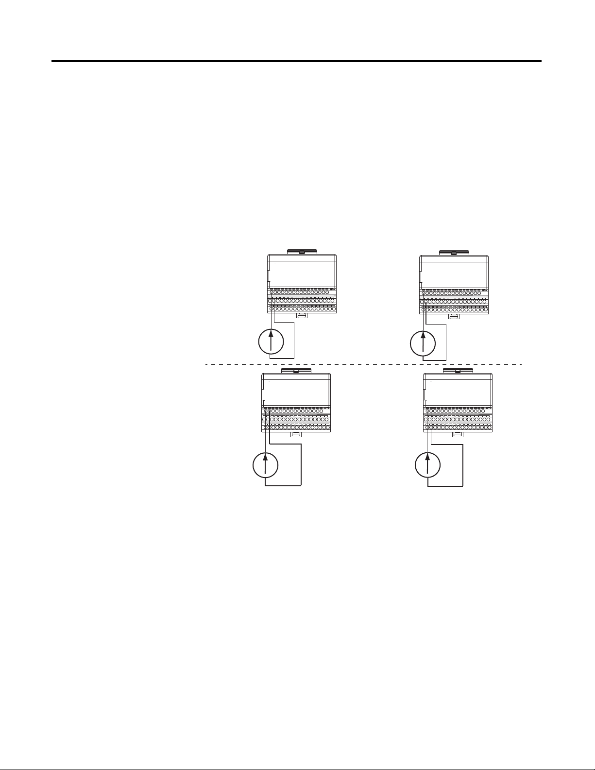
Voltage
Transmitter A
1794-TB3
1794-TB3
1794-TB3
1794-TB3
Analog Input
1794-IE8
Analog Input
1794-IE8
Analog Input
1794-IF4I
Analog Input
1794-IF4I
Voltage
Transmitter A
Voltage
Transmitter B
Voltage
Transmitter B
+
-
+
-
+
-
+
-
Wiring FLEX I/O Analog Input Modules
The wiring diagrams in show two methods of wiring the analog input
Module. In either case, users must determine whether the use of 1 or 2
sensors is appropriate to fulfill SIL2 requirements.
Figure 3.8 ControlLogix Analog Input Module Wiring
Wiring the Single-Ended Input Module in Voltage Mode
In addition to following the General Considerations when using Any FLEX
I/O Analog Input Module on page 3-7, make sure you use the correct
documentation (listed in Table 1.1 on page 1-5) to wire the module.
Figure 3.9 FLEX I/O Analog Input Module Wiring in Voltage Mode
Publication 1794-RM001G-EN-P - December 2011
Page 32
3-10 FLEX I/O Modules
RET
RET
RET
RET
Current
Source B
Current
Source B
Current
Source A
Current
Source A
1794-TB3
1794-TB3
1794-TB3
1794-TB3
1794-IE8
Analog Input
1794-IE8
Analog Input
1794-IE8
Analog Input
1794-IF4I
Analog Input
1794-IF4I
Wiring the Single-Ended Input Module in Current Mode
In addition to following the General Considerations when using Any FLEX
I/O Analog Input Module on page 3-7, before wiring the module, consider
the following application guideline:
• Placement of Other Devices in Current Loop: you can locate other
devices in an input channel’s current loop anywhere as long as the
current source can provide sufficient voltage to accommodate all of the
voltage drops (each module input is 250 ohms)
Publication 1794-RM001G-EN-P - December 2011
Page 33
FLEX I/O Modules 3-11
+
-
+
-
+
-
+
-
Thermocouple
Input Module
Thermocouple
Input Module
Thermocouple/
RTD/mV
Input Module
Thermocouple/
RTD/mV
Input Module
1794-TB3T
1794-TB3T
1794-TB3G
1794-TB3G
1794-IT8
1794-IT8
1794-IRT8
1794-IRT8
Wiring the Thermocouple Input Module
In addition to following the General Considerations when using Any FLEX
I/O Analog Input Module on page 3-7, before wiring the module, consider
the following application guideline:
• Wire to Same Input Channel on Both Modules: When wiring
thermocouples, wire two in parallel to two modules. Use the same
channel on each module to make sure of consistent temperature
readings.
Figure 3.10 FLEX I/O Analog Thermocouple Module Wiring
Publication 1794-RM001G-EN-P - December 2011
Page 34
3-12 FLEX I/O Modules
RTD
Input Module
RTD
Input Module
Thermocouple/
RTD/mV
Input Module
Thermocouple/
RTD/mV
Input Module
1794-TB3T
1794-TB3T
1794-TB3G
1794-TB3G
1794-IR8
1794-IR8
1794-IRT8
1794-IRT8
4-Wire RTD
3-Wire RTD
Note: 2, 3, or 4-wire RTDs can be used as applicable to the associated RTD input module.
Wiring the RTD Input Module
In addition to following the General Considerations when using Any FLEX
I/O Analog Input Module on page 3-7, before wiring the module, consider
the following application guideline:
• RTDs cannot be wired in parallel without severely affecting their
accuracy. Two sensors must be used.
Figure 3.11 FLEX I/O Analog RTD Module Wiring
Publication 1794-RM001G-EN-P - December 2011
Page 35

FLEX I/O Modules 3-13
Using Analog Output Modules
General Considerations when using Any FLEX I/O Analog Output Module
There are a number of general application considerations that you must follow
when applying the analog output modules in a SIL2 application:
• Proof Tests - Periodically (for example, once every several years) a
System Validation test must be performed. Manually, or automatically,
test outputs to make sure that all outputs are operational. Channel data
should be varied over the full operating range to make sure that the
corresponding field signal levels vary accordingly. For additional
information on , see Publication 1756-RM001
• Calibrate Outputs Periodically, As Necessary: FLEX I/O modules
ship from the factory with a highly accurate level of calibration.
However, because each application is different, users are responsible for
making sure their FLEX I/O modules are properly calibrated for their
specific application.
Users can employ tests in application program logic to determine when
a module requires recalibration. For example, to determine whether an
output module needs to be recalibrated, a user can determine a tolerance
band of accuracy for a specific application. The user can then measure
output values on multiple channels and compare those values to
acceptable values within the tolerance band. Based on the differences in
the comparison, the user could then determine whether recalibration is
necessary.
.
Calibration (and subsequent recalibration) is not a safety issue.
However, we recommend that each analog output be calibrated at least
every 3 years to verify the accuracy of the input signal and avoid
nuisance application shutdowns.
• For typical emergency shutdown (ESD) applications outputs must
be configured to De-energize: When configuring any FLEX I/O
output module, each output must be configured to de-energize in the
event of a fault and in the event of the controller going into program
mode. For exceptions to the typical ESD applications, see publication
1756-RM001
.
Publication 1794-RM001G-EN-P - December 2011
Page 36

3-14 FLEX I/O Modules
Timer done
Tim er
Outputs Faulted
Alarm to Operator
Outputs OK
ADD
Delta
Monitoring input
High Limit
MULT
Range
Tole rance %
Delta
Outputs Faulted
LIM
Low Limit
Output Echo
High Limit
Outputs OK
SUB
Delta
Monitoring input
Low Limit
• Wire Output Back to Input and Examination of Output Data
Feedback signal: Users must wire an analog output to an actuator and
then back to an analog input to monitor the output’s performance. (The
use of feedback transmitters to verify an output’s performance is
acceptable.) The application logic must examine the Data Feedback
value associated with each output point to make sure that the requested
output command from the controller was received by the module. The
value must be compared to the analog input that is monitoring the
output to make sure the value is in an acceptable range for the
application.
In the ladder diagram in Figure 3.12, a user-defined percentage of
acceptable deviation (that is, tolerance) is applied to the configured
range of the analog input and output (that is, range) and the result is
stored (that is, delta). This delta value is then added to and subtracted
from the monitoring analog input channel; the results define an
acceptable High and Low limit of deviation. The analog Output
Feedback is then compared to these limits to determine if the output are
working properly.
The output’s OK bit preconditions a Timer run that is preset to
accommodate an acceptable fault response time and any communication
filtering, or output, lags in the system. If the monitoring input value and
the Output Feedback miscompare for longer than the preset value, a
fault is registered with a corresponding alarm.
Figure 3.12 Monitoring an Analog Output with an Analog Input
Publication 1794-RM001G-EN-P - December 2011
The control, diagnostics and alarming functions must be performed in
sequence.
Page 37

FLEX I/O Modules 3-15
• When wiring two analog output modules in the same application, make
sure:
– Both modules use identical configuration.
– The same controller owns both modules.
• Monitor the ControlNet status bits for the associated module and
ensure that appropriate action is invoked via the application logic by
these status bits.
Publication 1794-RM001G-EN-P - December 2011
Page 38

3-16 FLEX I/O Modules
+
_
V RET
+
_
V RET
1794-TB3
1794-IF4I
Analog Output
Module
1794-TB3
1794-IE8
Analog Input
Module
Isolated Analog
Output Module
Isolated Analog
Input Module
1794-OF4I
1794-TB3
1794-TB3
Actuator
Actuator
1794-OE4
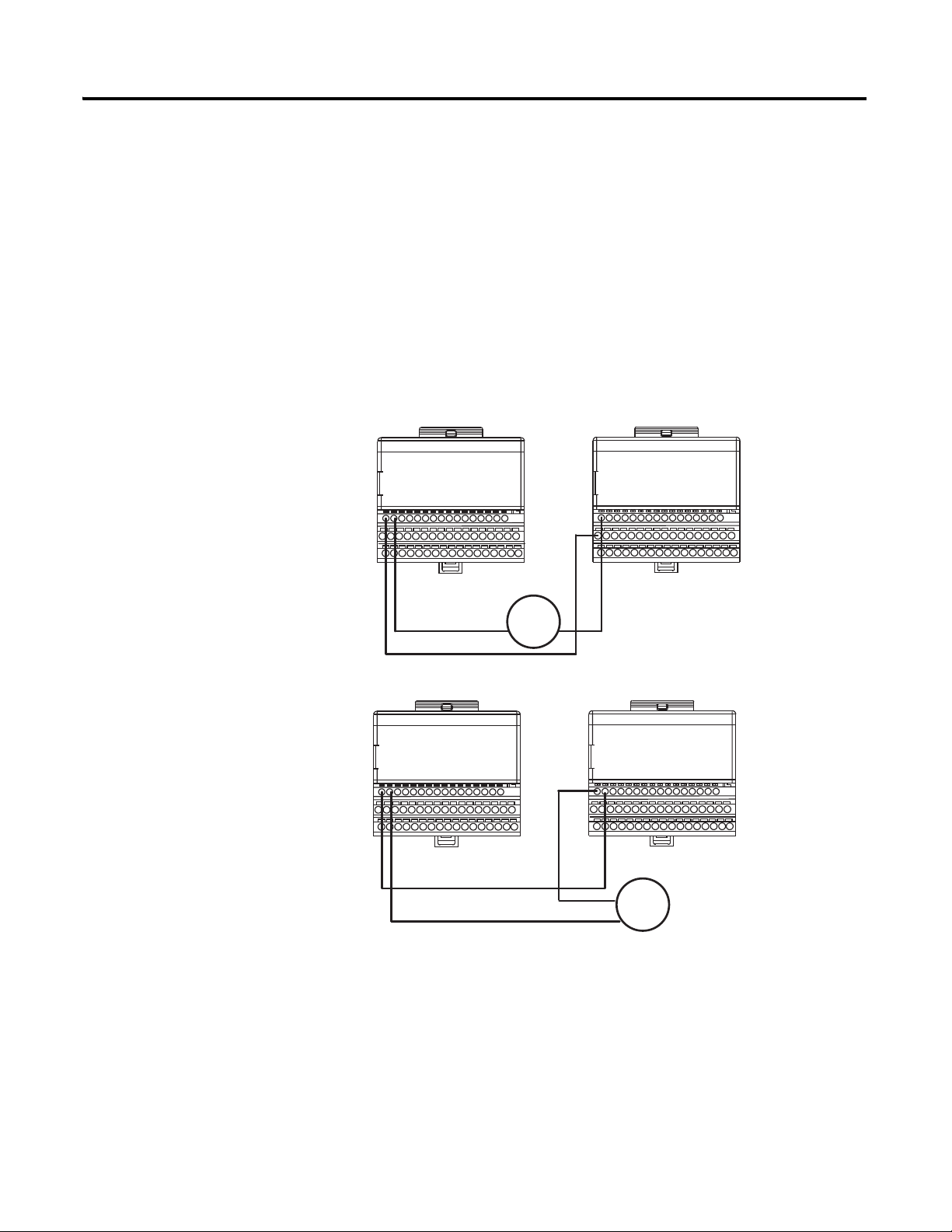
Wiring FLEX I/O Analog Output Modules
In general, good design practice dictates that each analog output must be wired
to a separate input terminal to make sure that the output is functioning
properly.
Wiring the Analog Output Module in Voltage Mode
Users must wire analog outputs to an actuator and then back to an analog
input to monitor the output performance.
Publication 1794-RM001G-EN-P - December 2011
Page 39
FLEX I/O Modules 3-17
1794-TB3
1794-IF4I
Analog Output
Module
1794-TB3
1794-IE8
Analog Input
Module
Isolated Analog
Output Module
Isolated Analog
Input Module
1794-OF4I
1794-TB3
1794-TB3
Actuator
Actuator
1794-OE4
Wiring the Analog Output Module in Current Mode
In addition to following the General Considerations when using Any FLEX
I/O Analog Output Module on page 3-13, consider the following application
guideline before wiring the module in current mode:
• Placement of Other Devices in Current Loop: you can locate other
devices in an output channel’s current loop anywhere as long as the
current source can provide sufficient voltage to accommodate all of the
voltage drops.
+
+
_
_
Publication 1794-RM001G-EN-P - December 2011
Page 40

3-18 FLEX I/O Modules
Checklist for SIL Inputs
The following checklist is required for planning, programming and start up of
SIL inputs. It may be used as a planning guide as well as during proof testing. If
used as a planning guide, the checklist can be saved as a record of the plan.
For programming or start-up, an individual checklist can be filled in for every
single SIL input channel in a system. This is the only way to make sure that the
requirements were fully and clearly implemented. This checklist can also be
used as documentation on the connection of external wiring to the application
program.
Input Check List for ControlLogix/FLEX I/O System
Company:
Site:
Loop definition:
SIL input channels in the:
No. All Input Module Requirements (apply to both digital and analog input modules) Yes No Comment
1 Is the RPI value set to an appropriate value for your application?
2 Are all modules owned by the same controller?
3 Have you performed proof tests on the system and modules?
4 Have you set up the fault routines?
5 Are control, diagnostics and alarming functions performed in sequence in application logic?
Note: The user must ensure that the hardware series and the firmware series and revision of the FLEX I/O
modules in their system are SIL2 certified.
6 Is the application logic monitoring one ControlNet status bit for the associated module and is appropriate
action invoked via the application logic by these bits?
No. Additional Digital Input Module-Only Requirements Yes No Comment
1 When two digital input modules are wired in the same application, do the following conditions exist:
• Both modules are owned by the same controller.
• Sensors are wired to separate input points.
• The operational state is ON.
• The non-operational state is. OFF.
• Configuration parameters (for example, RPI, filter values) are identical.
• Both input modules are on different ControlNet nodes.
2 For the standard input modules, is the Communication Format set to one of the Input Data choices?
No. Additional Analog Input Module-Only Requirements Yes No Comment
1 Have you calibrated the modules as often as required by your application?
2 Are you using ladder logic to compare the analog input data on two channels to make sure there is
concurrence within an acceptable range and that redundant data is used properly?
3 Have you written application logic to examine bits for any condition that may cause a fault and appropriate
fault routines to handle the fault condition?
4 When wiring the FLEX I/O analog module in voltage mode, are transmitter connections wired correctly?
5 When wiring the FLEX I/O analog module in current mode, are loop devices placed properly?
6 When wiring FLEX I/O thermocouple modules in parallel, have you wired to the same channel on each
module?
7 When wiring two FLEX I/O RTD modules, are two sensors used?
8 When two analog inputs are wired in the same application, are both modules on different ControlNet Nodes?
Publication 1794-RM001G-EN-P - December 2011
Page 41
FLEX I/O Modules 3-19
Checklist for SIL Outputs
The following checklist is required for planning, programming and start up of
SIL outputs. It may be used as a planning guide as well as during proof testing.
If used as a planning guide, the checklist can be saved as a record of the plan.
For programming or start-up, an individual requirement checklist must be
filled in for every single SIL output channel in a system. This is the only way to
make sure that the requirements are fully and clearly implemented. This
checklist can also be used as documentation on the connection of external
wiring to the application program.
Output Check List for ControlLogix/FLEX I/O System
Company:
Site:
Loop definition:
SIL output channels in the:
No. All Output Module Requirements (apply to both digital and analog output modules) Yes No Comment:
1 Have you performed proof tests on the modules?
2 Is the RPI value set to an appropriate value for your application?
3 Have you set up fault routines, including comparing output data with a corresponding input point?
4 If required, have you used external relays in your application to disconnect module power if a short or
other fault is detected on the module or isolated output in series?
5 Is the control of the external relay implemented in ladder logic?
6 Have you examined the Output Data feedback signal in application logic?
7 Are all outputs configured to deenergize in the event of a fault or the controller entering program
mode?
8 Do two modules of the same type, used in the same application, use identical configurations?
9 Does one controller own both modules if two of the same type are used in an application?
10 Are control, diagnostics and alarming functions performed in sequence in application logic?
11 Is the application logic monitoring one ControlNet status bit for the associated module and is
appropriate action invoked via the application logic by these bits?
No. Digital Output Module-Only Requirements Yes No Comment
1 For the standard output modules, is the Communication Format set to Output Data?
2 For standard output modules, have you wired the outputs to a corresponding input to validate that the
output is following its commanded state?
No. Analog Output Module-Only Requirements Yes No Comment
1 Have you calibrated the modules as often as required by your application?
2 When wiring the FLEX I/O analog output module in current mode, are loop devices placed properly?
3 Have you written application logic to examine bits for any condition that may cause a fault and
appropriate fault routines to handle the fault condition?
Publication 1794-RM001G-EN-P - December 2011
Page 42

3-20 FLEX I/O Modules
Notes:
Publication 1794-RM001G-EN-P - December 2011
Page 43

Chapter
4
General Requirements for
Application Software
Refer to publication 1756-RM001, Using ControlLogix in SIL2 Applications.
1 Publication 1794-RM001G-EN-P - December 2011
Page 44

4-2 General Requirements for Application Software
Notes:
Publication 1794-RM001G-EN-P - December 2011
Page 45

Chapter
Technical SIL2 Requirements for the
Application Program
Refer to publication 1756-RM001 for Technical SIL2 Requirements for the
application program.
5
1 Publication 1794-RM001G-EN-P - December 2011
Page 46

5-2 Technical SIL2 Requirements for the Application Program
Notes:
Publication 1794-RM001G-EN-P - December 2011
Page 47

Failure Estimates
The following tables list the failure estimates for the FLEX I/O products
included in this manual for different proof test intervals.
Table A.1 MTBF Field Data and Per Module PFD Estimates - T1 = 1 year
Appendix
A
Catalog Number: Description:
1794-ACN15 ControlNet Single Media Adapter 8,223,684 1.22E-07 2.15E-06
1794-ACNR15 ControlNet Redundant Media Adapter 8,223,684 1.22E-07 2.15E-06
1794-AENT 10/100Mb Ethernet Communication Adapter 691,134 1.45E-06 2.76E-05
1794-AENTR 10/100Mb Ethernet Redundant Communication Adapter 1,268,070 7.89E-07 1.45E-05
1794-IB10XOB6 10 Input/6 Output Module 4,943,442 2.02E-07 3.60E-06
1794-IB16 16 Sink Input Module 4,105,090 2.44E-07 4.34E-06
1794-IE8 Analog Input Module 37,952,679 2.63E-08 4.64E-07
1794-IF2XOF2I Isolated Analog Input/Output Module 25,296,960 3.95E-08 6.97E-07
1794-IF4I Isolated Analog Input Module 11,746,343 8.51E-08 1.50E-06
1794-IJ2 Frequency Counter Module 2,418,321 4.14E-07 7.45E-06
1794-IP4 Pulse Counter Module 2,375,360 4.21E-07 7.58E-06
1794-IR8 RTD Input Module 6,191,655 1.62E-07 2.87E-06
1794-IRT8 TC/RTD/mV Input Module 1,182,438 8.46E-07 1.56E-05
1794-IT8 Thermocouple Input Module 1,564,324 6.39E-07 1.17E-05
1794-OB16 16 Source Output Module 1,883,594 5.31E-07 9.62E-06
1794-OB16P Protected Output Module 2,135,280 4.68E-07 8.46E-06
1794-OB8EP Protected Output Module
(MTBF)
2,389,669
(1)
(2)
(3)
λ
4.18E-07 7.54E-06
Estimated PFD
1oo2
1794-OE4 Analog Output Module 23,807,086 4.20E-08 7.41E-07
1794-OF4I Isolated Analog Output Module 7,191,128 1.39E-07 2.47E-06
1794-OW8 Relay Output Module 14,766,876 6.77E-08 1.20E-06
1794-TB3 Terminal Base Units
1794-TB3G Generic Terminal Base Units 27,320,800 3.66E-08 6.45E-07
1794-TB3GS Generic Terminal Base Units 46,425,600 2.15E-08 3.79E-07
1794-TB3S Terminal Base Unit
1794-TB3T Temperature Terminal Base Units
1794-TB3TS Temperature Terminal Base Units
1794-TBN Terminal Base Units 75,716,615 1.32E-08 2.32E-07
1794-TBNF Fused Terminal Base Units
1794-ACNR15XT ControlNet Redundant Media Adapter 8,223,684 1.22E-07 2.15E-06
1 Publication 1794-RM001G-EN-P - December 2011
21,128,346
71,433,747
73,096,226
75,763,399
4,812,320
(2)
(2)
(2)
(2)
(2)
4.73E-08 8.35E-07
1.40E-08 2.46E-07
1.37E-08 2.41E-07
1.32E-08 2.32E-07
2.08E-07 3.70E-06
Page 48
A-2 Failure Estimates
Table A.1 MTBF Field Data and Per Module PFD Estimates - T1 = 1 year
Catalog Number: Description:
(MTBF)
(1)
(3)
λ
Estimated PFD
1oo2
1794-AENTRXT 10/100Mb Ethernet Redundant Communication Adapter 1,268,070 7.89E-07 1.45E-05
1794-OB8EPXT 8 Protected Output Module 14,771,049 6.77E-08 1.20E-06
1794-IB16XT 16 Sink Input Module 35,587,189 2.81E-08 4.95E-07
1794-OB16PXT 16 Protected Output Module 26,709,401 3.74E-08 6.60E-07
1794-IB10XOB6XT 10 Input/6 Output Combo Module 22,202,487 4.50E-08 7.94E-07
1794-OW8XT 8 Relay Output Module 18,518,519 5.40E-08 9.53E-07
1794-IE4XOE2XT 4 Input/2 Output Analog Combo Module 11,800,802 8.47E-08 1.50E-06
1794-IE8XT 8 Input analog Module 14,041,000 7.12E-08 1.26E-06
1794-OE4XT 4 Output Analog Module 11,381,744 8.79E-08 1.55E-06
1794-IF2XOF2IXT 2 Input/2 Output Isolated Analog Combo Module 6,317,918 1.58E-07 2.81E-06
1794-IF4IXT 4 Isolated Input Analog Module 7,297,140 1.37E-07 2.43E-06
1794-IF4ICFXT 4 Isolated Input Analog Module 7,297,140 1.37E-07 2.43E-06
1794-OF4IXT 4 Isolated Output Analog Module 5,493,902 1.82E-07 3.24E-06
1794-IJ2XT 2 Ch. Frequency Counter Module 11,714,128 8.54E-08 1.51E-06
1794-IRT8XT 8 TC/RTD Input Analog Module 8,204,792 1.22E-07 2.16E-06
(1)
MTBF measured in hours.
(2)
Calculated using field-based values for components
(3)
λ = Failure Rate = 1 / MTBF
Table A.2 MTBF Field Data and Per Module PFD Estimates - T1 = 2 years
Catalog Number: Description:
(MTBF)
(1)
λ
(3)
Estimated
PFD 1oo2
1794-ACN15 ControlNet Single Media Adapter 8,223,684 1.22E-07 4.33E-06
1794-ACNR15 ControlNet Redundant Media Adapter 8,223,684 1.22E-07 4.33E-06
1794-AENT 10/100Mb Ethernet Communication Adapter 691,134 1.45E-06 5.92E-05
1794-AENTR 10/100Mb Ethernet Redundant Communication Adapter 1,268,070 7.89E-07 3.02E-05
1794-IB10XOB6 10 Input/6 Output Module 4,943,442 2.02E-07 7.27E-06
1794-IB16 16 Sink Input Module 4,105,090 2.44E-07 8.79E-06
1794-IE8 Analog Input Module 37,952,679 2.63E-08 9.28E-07
1794-IF2XOF2I Isolated Analog Input/Output Module 25,296,960 3.95E-08 1.39E-06
1794-IF4I Isolated Analog Input Module 11,746,343 8.51E-08 3.02E-06
1794-IJ2 Frequency Counter Module 2,418,321 4.14E-07 1.52E-05
1794-IP4 Pulse Counter Module 2,375,360 4.21E-07 1.55E-05
1794-IR8 RTD Input Module 6,191,655 1.62E-07 5.77E-06
1794-IRT8 TC/RTD/mV Input Module 1,182,438 8.46E-07 3.26E-05
Publication 1794-RM001G-EN-P - December 2011
Page 49

Table A.2 MTBF Field Data and Per Module PFD Estimates - T1 = 2 years
Failure Estimates A-3
Catalog Number: Description:
(MTBF)
(1)
λ
(3)
Estimated
PFD 1oo2
1794-IT8 Thermocouple Input Module 1,564,324 6.39E-07 2.41E-05
1794-OB16 16 Source Output Module 1,883,594 5.31E-07 1.98E-05
1794-OB16P Protected Output Module 2,135,280 4.68E-07 1.73E-05
1794-OB8EP Protected Output Module
2,389,669
(2)
4.18E-07 1.54E-05
1794-OE4 Analog Output Module 23,807,086 4.20E-08 1.48E-06
1794-OF4I Isolated Analog Output Module 7,191,128 1.39E-07 4.96E-06
1794-OW8 Relay Output Module 14,766,876 6.77E-08 2.40E-06
1794-TB3 Terminal Base Units
21,128,346
(2)
4.73E-08 1.67E-06
1794-TB3G Generic Terminal Base Units 27,320,800 3.66E-08 1.29E-06
1794-TB3GS Generic Terminal Base Units 46,425,600 2.15E-08 7.58E-07
1794-TB3S Terminal Base Unit
1794-TB3T Temperature Terminal Base Units
1794-TB3TS Temperature Terminal Base Units
71,433,747
73,096,226
75,763,399
(2)
1.40E-08 4.92E-07
(2)
1.37E-08 4.81E-07
(2)
1.32E-08 4.64E-07
1794-TBN Terminal Base Units 75,716,615 1.32E-08 4.64E-07
1794-TBNF Fused Terminal Base Units
4,812,320
(2)
2.08E-07 7.47E-06
1794-ACNR15XT ControlNet Redundant Media Adapter 8,223,684 1.22E-07 4.33E-06
1794-AENTRXT 10/100Mb Ethernet Redundant Communication Adapter 1,268,070 7.89E-07 3.02E-05
1794-OB8EPXT 8 Protected Output Module 14,771,049 6.77E-08 2.40E-06
1794-IB16XT 16 Sink Input Module 35,587,189 2.81E-08 9.90E-07
1794-OB16PXT 16 Protected Output Module 26,709,401 3.74E-08 1.32E-06
1794-IB10XOB6XT 10 Input/6 Output Combo Module 22,202,487 4.50E-08 1.59E-06
1794-OW8XT 8 Relay Output Module 18,518,519 5.40E-08 1.91E-06
1794-IE4XOE2XT 4 Input/2 Output Analog Combo Module 11,800,802 8.47E-08 3.00E-06
1794-IE8XT 8 Input analog Module 14,041,000 7.12E-08 2.52E-06
1794-OE4XT 4 Output Analog Module 11,381,744 8.79E-08 3.12E-06
1794-IF2XOF2IXT 2 Input/2 Output Isolated Analog Combo Module 6,317,918 1.58E-07 5.66E-06
1794-IF4IXT 4 Isolated Input Analog Module 7,297,140 1.37E-07 4.89E-06
1794-IF4ICFXT 4 Isolated Input Analog Module 7,297,140 1.37E-07 4.89E-06
1794-OF4IXT 4 Isolated Output Analog Module 5,493,902 1.82E-07 6.52E-06
1794-IJ2XT 2 Ch. Frequency Counter Module 11,714,128 8.54E-08 3.03E-06
1794-IRT8XT 8 TC/RTD Input Analog Module 8,204,792 1.22E-07 4.34E-06
(1)
MTBF measured in hours.
(2)
Calculated using field-based values for components
(3)
λ = Failure Rate = 1 / MTB
Publication 1794-RM001G-EN-P - December 2011
Page 50

A-4 Failure Estimates
Table A.3 MTBF Field Data and Per Module PFD Estimates - T1 = 5 years
Catalog Number: Description:
(MTBF)
(1)
(3)
λ
Estimated
PFD 1oo2
1794-ACN15 ControlNet Single Media Adapter 8,223,684 1.22E-07 1.10E-05
1794-ACNR15 ControlNet Redundant Media Adapter 8,223,684 1.22E-07 1.10E-05
1794-AENT 10/100Mb Ethernet Communication Adapter 691,134 1.45E-06 1.79E-04
1794-AENTR 10/100Mb Ethernet Redundant Communication Adapter 1,268,070 7.89E-07 8.47E-05
1794-IB10XOB6 10 Input/6 Output Module 4,943,442 2.02E-07 1.88E-05
1794-IB16 16 Sink Input Module 4,105,090 2.44E-07 2.28E-05
1794-IE8 Analog Input Module 37,952,679 2.63E-08 2.33E-06
1794-IF2XOF2I Isolated Analog Input/Output Module 25,296,960 3.95E-08 3.50E-06
1794-IF4I Isolated Analog Input Module 11,746,343 8.51E-08 7.64E-06
1794-IJ2 Frequency Counter Module 2,418,321 4.14E-07 4.05E-05
1794-IP4 Pulse Counter Module 2,375,360 4.21E-07 4.13E-05
1794-IR8 RTD Input Module 6,191,655 1.62E-07 1.48E-05
1794-IRT8 TC/RTD/mV Input Module 1,182,438 8.46E-07 9.19E-05
1794-IT8 Thermocouple Input Module 1,564,324 6.39E-07 6.62E-05
1794-OB16 16 Source Output Module 1,883,594 5.31E-07 5.36E-05
1794-OB16P Protected Output Module 2,135,280 4.68E-07 4.65E-05
1794-OB8EP Protected Output Module
2,389,669
(2)
4.18E-07 4.10E-05
1794-OE4 Analog Output Module 23,807,086 4.20E-08 3.73E-06
1794-OF4I Isolated Analog Output Module 7,191,128 1.39E-07 1.27E-05
1794-OW8 Relay Output Module 14,766,876 6.77E-08 6.05E-06
1794-TB3 Terminal Base Units
21,128,346
(2)
4.73E-08 4.21E-06
1794-TB3G Generic Terminal Base Units 27,320,800 3.66E-08 3.24E-06
1794-TB3GS Generic Terminal Base Units 46,425,600 2.15E-08 1.90E-06
1794-TB3S Terminal Base Unit
1794-TB3T Temperature Terminal Base Units
1794-TB3TS Temperature Terminal Base Units
71,433,747
73,096,226
75,763,399
(2)
(2)
(2)
1.40E-08 1.23E-06
1.37E-08 1.20E-06
1.32E-08 1.16E-06
1794-TBN Terminal Base Units 75,716,615 1.32E-08 1.16E-06
1794-TBNF Fused Terminal Base Units
4,812,320
(2)
2.08E-07 1.93E-05
1794-ACNR15XT ControlNet Redundant Media Adapter 8,223,684 1.22E-07 1.10E-05
1794-AENTRXT 10/100Mb Ethernet Redundant Communication Adapter 1,268,070 7.89E-07 8.47E-05
1794-OB8EPXT 8 Protected Output Module 14,771,049 6.77E-08 6.05E-06
1794-IB16XT 16 Sink Input Module 35,587,189 2.81E-08 2.48E-06
1794-OB16PXT 16 Protected Output Module 26,709,401 3.74E-08 3.32E-06
Publication 1794-RM001G-EN-P - December 2011
Page 51

Table A.3 MTBF Field Data and Per Module PFD Estimates - T1 = 5 years
Failure Estimates A-5
Catalog Number: Description:
(MTBF)
(1)
(3)
λ
Estimated
PFD 1oo2
1794-IB10XOB6XT 10 Input/6 Output Combo Module 22,202,487 4.50E-08 4.00E-06
1794-OW8XT 8 Relay Output Module 18,518,519 5.40E-08 4.81E-06
1794-IE4XOE2XT 4 Input/2 Output Analog Combo Module 11,800,802 8.47E-08 7.61E-06
1794-IE8XT 8 Input analog Module 14,041,000 7.12E-08 6.37E-06
1794-OE4XT 4 Output Analog Module 11,381,744 8.79E-08 7.89E-06
1794-IF2XOF2IXT 2 Input/2 Output Isolated Analog Combo Module 6,317,918 1.58E-07 1.45E-05
1794-IF4IXT 4 Isolated Input Analog Module 7,297,140 1.37E-07 1.25E-05
1794-IF4ICFXT 4 Isolated Input Analog Module 7,297,140 1.37E-07 1.25E-05
1794-OF4IXT 4 Isolated Output Analog Module 5,493,902 1.82E-07 1.68E-05
1794-IJ2XT 2 Ch. Frequency Counter Module 11,714,128 8.54E-08 7.67E-06
1794-IRT8XT 8 TC/RTD Input Analog Module 8,204,792 1.22E-07 1.11E-05
(1)
MTBF measured in hours.
(2)
Calculated using field-based values for components
(3)
λ = Failure Rate = 1 / MTBF
Table A.4 MTBF Field Data and Per Module PFH Estimates - T1 = 1 year
Catalog Number: Description:
(MTBF)
(1)
λ
(3)
Estimated
PFH 1oo2
1794-ACN15 ControlNet Single Media Adapter 8,223,684 1.22E-07 8.64E-10
1794-ACNR15 ControlNet Redundant Media Adapter 8,223,684 1.22E-07 8.64E-10
1794-AENT 10/100Mb Ethernet Communication Adapter 691,134 1.45E-06 1.19E-08
1794-AENTR 10/100Mb Ethernet Redundant Communication Adapter
1,268,070
(2)
7.89E-07 6.05E-09
1794-IB10XOB6 10 Input/6 Output Module 4,943,442 2.02E-07 1.45E09
1794-IB16 16 Sink Input Module 4,105,090 2.44E-07 1.76E-09
1794-IE8 Analog Input Module 37,952,679 2.63E-08 1.85E-10
1794-IF2XOF2I Isolated Analog Input/Output Module 25,296,960 3.95E-08 2.78E-10
1794-IF4I Isolated Analog Input Module 11,746,343 8.51E-08 6.02E-10
1794-IJ2 Frequency Counter Module 2,418,321 4.14E-07 3.04E09
1794-IP4 Pulse Counter Module 2,375,360 4.21E-07 3.10E09
1794-IR8 RTD Input Module 6,191,655 1.62E-07 1.15E-09
1794-IRT8 TC/RTD/mV Input Module 1,182,438 8.46E-07 6.53E-09
1794-IT8 Thermocouple Input Module 1,564,324 6.39E-07 4.82E-09
1794-OB16 16 Source Output Module 1,883,594 5.31E-07 3.96E-09
1794-OB16P Protected Output Module 2,135,280 4.68E-07 3.47E09
1794-OB8EP Protected Output Module
2,389,669
(2)
Publication 1794-RM001G-EN-P - December 2011
4.18E-07 3.08E09
Page 52

A-6 Failure Estimates
Table A.4 MTBF Field Data and Per Module PFH Estimates - T1 = 1 year
Catalog Number: Description:
(MTBF)
(1)
λ
(3)
Estimated
PFH 1oo2
1794-OE4 Analog Output Module 23,807,086 4.20E-08 2.96E-10
1794-OF4I Isolated Analog Output Module 7,191,128 1.39E-07 9.90E10
1794-OW8 Relay Output Module 14,766,876 6.77E-08 4.78E-10
1794-TB3 Terminal Base Units
21,128,346
(2)
4.73E-08 3.33E10
1794-TB3G Generic Terminal Base Units 27,320,800 3.66E-08 2.57E10
1794-TB3GS Generic Terminal Base Units 46,425,600 2.15E-08 1.51E10
1794-TB3S Terminal Base Unit
1794-TB3T Temperature Terminal Base Units
1794-TB3TS Temperature Terminal Base Units
71,433,747
73,096,226
75,763,399
(2)
1.40E-08 9.82E11
(2)
1.37E-08 9.59E11
(2)
1.32E-08 9.25E11
1794-TBN Terminal Base Units 75,716,615 1.32E-08 9.26E-11
1794-TBNF Fused Terminal Base Units
4,812,320
(2)
2.08E-07 1.49E09
1794-ACNR15XT ControlNet Redundant Media Adapter 8,223,684 1.22E-07 8.64E-10
1794-AENTRXT 10/100Mb Ethernet Redundant Communication Adapter
1,268,070
(2)
7.89E-07 6.05E-09
1794-OB8EPXT 8 Protected Output Module 14,771,049 6.77E-08 4.78E-10
1794-IB16XT 16 Sink Input Module 35,587,189 2.81E-08 1.97E-10
1794-OB16PXT 16 Protected Output Module 26,709,401 3.74E-08 2.63E-10
1794-IB10XOB6XT 10 Input/6 Output Combo Module 22,202,487 4.50E-08 3.17E-10
1794-OW8XT 8 Relay Output Module 18,518,519 5.40E-08 3.80E-10
1794-IE4XOE2XT 4 Input/2 Output Analog Combo Module 11,800,802 8.47E-08 5.99E-10
1794-IE8XT 8 Input analog Module 14,041,000 7.12E-08 5.03E-10
1794-OE4XT 4 Output Analog Module 11,381,744 8.79E-08 6.22E-10
1794-IF2XOF2IXT 2 Input/2 Output Isolated Analog Combo Module 6,317,918 1.58E-07 1.13E-09
1794-IF4IXT 4 Isolated Input Analog Module 7,297,140 1.37E-07 9.75E-10
1794-IF4ICFXT 4 Isolated Input Analog Module 7,297,140 1.37E-07 9.75E-10
1794-OF4IXT 4 Isolated Output Analog Module 5,493,902 1.82E-07 1.30E-09
1794-IJ2XT 2 Ch. Frequency Counter Module 11,714,128 8.54E-08 6.04E-10
(1)
MTBF measured in hours.
(2)
Calculated using field-based values for components
(3)
λ = Failure Rate = 1 / MTBF
Publication 1794-RM001G-EN-P - December 2011
Page 53

Table A.5 MTBF Field Data and Per Module PFH Estimates - T1 = 2 years
Failure Estimates A-7
Catalog Number: Description:
(MTBF)
(1)
λ
(3)
Estimated
PFH 1oo2
1794-ACN15 ControlNet Single Media Adapter 8,223,684 1.22E-07 8.76E-10
1794-ACNR15 ControlNet Redundant Media Adapter 8,223,684 1.22E-07 8.76E-10
1794-AENT 10/100Mb Ethernet Communication Adapter 691,134 1.45E-06 6.58E-09
1794-AENTR 10/100Mb Ethernet Redundant Communication Adapter 1,268,070 7.89E-07 6.58E-09
1794-IB10XOB6 10 Input/6 Output Module 4,943,442 2.02E-07 1.49E-09
1794-IB16 16 Sink Input Module 4,105,090 2.44E-07 1.81E-09
1794-IE8 Analog Input Module 37,952,679 2.63E-08 1.86E-10
1794-IF2XOF2I Isolated Analog Input/Output Module 25,296,960 3.95E-08 2.79E-10
1794-IF4I Isolated Analog Input Module 11,746,343 8.51E-08 6.08E-10
1794-IJ2 Frequency Counter Module 2,418,321 4.14E-07 3.19E-09
1794-IP4 Pulse Counter Module 2,375,360 4.21E-07 3.25E-09
1794-IR8 RTD Input Module 6,191,655 1.62E-07 1.18E-09
1794-IRT8 TC/RTD/mV Input Module 1,182,438 8.46E-07 7.14E-09
1794-IT8 Thermocouple Input Module 1,564,324 6.39E-07 5.17E-09
1794-OB16 16 Source Output Module 1,883,594 5.31E-07 4.20E-09
1794-OB16P Protected Output Module 2,135,280 4.68E-07 3.65E-09
1794-OB8EP Protected Output Module
2,389,669
(2)
4.18E-07 3.23E-09
1794-OE4 Analog Output Module 23,807,086 4.20E-08 2.97E-10
1794-OF4I Isolated Analog Output Module 7,191,128 1.39E-07 1.01E-09
1794-OW8 Relay Output Module 14,766,876 6.77E-08 4.82E-10
1794-TB3 Terminal Base Units
21,128,346
(2)
4.73E-08 3.35E-10
1794-TB3G Generic Terminal Base Units 27,320,800 3.66E-08 2.59E-10
1794-TB3GS Generic Terminal Base Units 46,425,600 2.15E-08 1.52E-10
1794-TB3S Terminal Base Unit
1794-TB3T Temperature Terminal Base Units
1794-TB3TS Temperature Terminal Base Units
71,433,747
73,096,226
75,763,399
(2)
(2)
(2)
1.40E-08 9.83E-11
1.37E-08 9.61E-11
1.32E-08 9.27E116
1794-TBN Terminal Base Units 75,716,615 1.32E-08 9.27E-11
1794-TBNF Fused Terminal Base Units
4,812,320
(2)
2.08E-07 1.53E-09
1794-ACNR15XT ControlNet Redundant Media Adapter 8,223,684 1.22E-07 8.76E-10
1794-AENTRXT 10/100Mb Ethernet Redundant Communication Adapter 1,268,070 7.89E-07 6.58E-09
1794-OB8EPXT 8 Protected Output Module 14,771,049 6.77E-08 4.82E-10
1794-IB16XT 16 Sink Input Module 35,587,189 2.81E-08 1.98E-10
1794-OB16PXT 16 Protected Output Module 26,709,401 3.74E-08 2.64E-10
Publication 1794-RM001G-EN-P - December 2011
Page 54

A-8 Failure Estimates
Table A.5 MTBF Field Data and Per Module PFH Estimates - T1 = 2 years
Catalog Number: Description:
(MTBF)
(1)
λ
(3)
Estimated
PFH 1oo2
1794-IB10XOB6XT 10 Input/6 Output Combo Module 22,202,487 4.50E-08 3.19E-10
1794-OW8XT 8 Relay Output Module 18,518,519 5.40E-08 3.83E-10
1794-IE4XOE2XT 4 Input/2 Output Analog Combo Module 11,800,802 8.47E-08 6.05E-10
1794-IE8XT 8 Input analog Module 14,041,000 7.12E-08 5.07E-10
1794-OE4XT 4 Output Analog Module 11,381,744 8.79E-08 6.28E-10
1794-IF2XOF2IXT 2 Input/2 Output Isolated Analog Combo Module 6,317,918 1.58E-07 1.15E-09
1794-IF4IXT 4 Isolated Input Analog Module 7,297,140 1.37E-07 9.91E-10
1794-IF4ICFXT 4 Isolated Input Analog Module 7,297,140 1.37E-07 9.91E-10
1794-OF4IXT 4 Isolated Output Analog Module 5,493,902 1.82E-07 1.33E-09
1794-IJ2XT 2 Ch. Frequency Counter Module 11,714,128 8.54E-08 6.10E-10
1794-IRT8XT 8 TC/RTD Input Analog Module 8,204,792 1.22E-07 8.79E-10
(1)
MTBF measured in hours.
(2)
Calculated using field-based values for components
(3)
λ = Failure Rate = 1 / MTBF
Table A.6 MTBF Field Data and Per Module PFH Estimates - T1 = 5 years
Catalog Number: Description:
(MTBF)
(1)
λ
(3)
Estimated
PFH 1oo2
1794-ACN15 ControlNet Single Media Adapter 8,223,684 1.22E-07 9.14E-10
1794-ACNR15 ControlNet Redundant Media Adapter 8,223,684 1.22E-07 9.14E-10
1794-AENT 10/100Mb Ethernet Communication Adapter 691,134 1.45E-06 1.91E-08
1794-AENTR 10/100Mb Ethernet Redundant Communication Adapter 1,268,070 7.89E-07 8.17E-09
1794-IB10XOB6 10 Input/6 Output Module 4,943,442 2.02E-07 1.59E-09
1794-IB16 16 Sink Input Module 4,105,090 2.44E-07 1.96E-09
1794-IE8 Analog Input Module 37,952,679 2.63E-08 1.87E-10
1794-IF2XOF2I Isolated Analog Input/Output Module 25,296,960 3.95E-08 2.83E-10
1794-IF4I Isolated Analog Input Module 11,746,343 8.51E-08 6.27E-10
1794-IJ2 Frequency Counter Module 2,418,321 4.14E-07 3.62E-09
1794-IP4 Pulse Counter Module 2,375,360 4.21E-07 3.70E-09
1794-IR8 RTD Input Module 6,191,655 1.62E-07 1.24E-09
1794-IRT8 TC/RTD/mV Input Module 1,182,438 8.46E-07 8.97E-09
1794-IT8 Thermocouple Input Module 1,564,324 6.39E-07 6.22E-09
1794-OB16 16 Source Output Module 1,883,594 5.31E-07 4.92E-09
Publication 1794-RM001G-EN-P - December 2011
Page 55

Table A.6 MTBF Field Data and Per Module PFH Estimates - T1 = 5 years
Failure Estimates A-9
Catalog Number: Description:
(MTBF)
(1)
λ
(3)
Estimated
PFH 1oo2
1794-OB16P Protected Output Module 2,135,280 4.68E-07 4.21E-09
1794-OB8EP Protected Output Module
2,389,669
(2)
4.18E-07 3.68E-09
1794-OE4 Analog Output Module 23,807,086 4.20E-08 3.02E-10
1794-OF4I Isolated Analog Output Module 7,191,128 1.39E-07 3.76E-10
1794-OW8 Relay Output Module 14,766,876 6.77E-08 4.94E-10
1794-TB3 Terminal Base Units
21,128,346
(2)
4.73E-08 3.41E-10
1794-TB3G Generic Terminal Base Units 27,320,800 3.66E-08 2.62E-10
1794-TB3GS Generic Terminal Base Units 46,425,600 2.15E-08 1.53E-10
1794-TB3S Terminal Base Unit
1794-TB3T Temperature Terminal Base Units
1794-TB3TS Temperature Terminal Base Units
71,433,747
73,096,226
75,763,399
(2)
(2)
(2)
1.40E-08 9.88E-11
1.37E-08 9.66E-11
1.32E-08 9.31E-11
1794-TBN Terminal Base Units 75,716.615 1.32E-08 9.32E-11
1794-TBNF Fused Terminal Base Units
4,812,320
(2)
2.08E-07 1.64E-09
1794-ACNR15XT ControlNet Redundant Media Adapter 8,223,684 1.22E-07 9.14E-10
1794-AENTRXT 10/100Mb Ethernet Redundant Communication Adapter 1,268,070 7.89E-07 8.17E-09
1794-OB8EPXT 8 Protected Output Module 14,771,049 6.77E-08 4.93E-10
1794-IB16XT 16 Sink Input Module 35,587,189 2.81E-08 2.00E-10
1794-OB16PXT 16 Protected Output Module 26,709,401 3.74E-08 2.68E-10
1794-IB10XOB6XT 10 Input/6 Output Combo Module 22,202,487 4.50E-08 3.24E-10
1794-OW8XT 8 Relay Output Module 18,518,519 5.40E-08 3.90E-10
1794-IE4XOE2XT 4 Input/2 Output Analog Combo Module 11,800,802 8.47E-08 6.24E-10
1794-IE8XT 8 Input analog Module 14,041,000 7.12E-08 5.20E-10
1794-OE4XT 4 Output Analog Module 11,381,744 8.79E-08 6.48E-10
1794-IF2XOF2IXT 2 Input/2 Output Isolated Analog Combo Module 6,317,918 1.58E-07 1.21E-09
1794-IF4IXT 4 Isolated Input Analog Module 7,297,140 1.37E-07 1.04E-09
1794-IF4ICFXT 4 Isolated Input Analog Module 7,297,140 1.37E-07 1.04E-09
1794-OF4IXT 4 Isolated Output Analog Module 5,493,902 1.82E-07 1.42E-09
1794-IJ2XT 2 Ch. Frequency Counter Module 11,714,128 8.54E-08 6.29E-10
1794-IRT8XT 8 TC/RTD Input Analog Module 8,204,792 1.22E-07 9.16E-10
(1)
MTBF measured in hours.
(2)
Calculated using field-based values for components
(3)
λ = Failure Rate = 1 / MTBF
Publication 1794-RM001G-EN-P - December 2011
Page 56

A-10 Failure Estimates
Notes:
Publication 1794-RM001G-EN-P - December 2011
Page 57

Index
A
Analog input modules 3-7–3-8
Analog output modules 3-13–3-15
Application program
Technical SIL2 requirements
5-1
C
Calibration 3-7, 3-13
Communication
ControlNet
Communications modules 2-1
ControlNet module 2-1
Documentation 2-3
Control and information protocol
Definition
ControlNet module 2-1
2-1
Preface-1
D
Diagnostic coverage
Definition
Documentation
Communications modules
Preface-1
2-3
E
European norm.
Definition
Preface-1
F
Fault reporting
Analog input modules
Analog output modules 3-14
Digital input modules 3-3
Digital output modules 3-4, 3-5
3-7
G
Get system value (GSV)
Defintion
Preface-1
I
I/O modules 3-1–3-19
Analog input modules 3-7–3-8
Analog output modules 3-13–3-15
Calibration 3-7, 3-13
Digital input modules 3-2–3-4
Digital output modules 3-6
Fault reporting 3-3, 3-4, 3-5, 3-7, 3-14
Proof tests 3-2, 3-4, 3-7, 3-13
Wiring analog input modules 3-9–3-15
Wiring analog output modules 3-16–
3-17
Wiring digital input modules 3-3
Wiring digital output modules 3-5, 3-6
M
Mean time between failures (MTBF)
Definition
Mean time to restoration
Definition
Preface-2
Preface-2
P
Probability of failure on demand (PFD)
1-8–1-11
Calculations for each catalog number
1-8
Definition Preface-2
Probability of failure per hour (PFH) 1-8–
1-11
Calculations for each catalog number
1-10
Definition Preface-2
Proof tests 1-3, 3-2, 3-4, 3-7, 3-13
R
RSLogix 5000 Preface-2
General requirements 4-1
S
SIL compliance
Distribution and weight
SIL loop example 1-2
SIL2 requirements
For the application program
SIL2-certified components
Complete list of ControlLogix catalog
numbers
Software
General requirements
RSLogix 5000 Preface-2
Spurious failure estimates A-1
1-13
5-1
1-5
4-1
T
Terminology
Used throughout manual
Preface-1
W
Publication 1794-RM001G-EN-P - December 2011
Page 58

2 Index
Wiring I/O modules
Analog input modules
3-9–3-15
Analog output modules 3-16–3-17
Digital input modules 3-3
Digital output modules 3-5, 3-6
Publication 1794-RM001G-EN-P - December 2011
Page 59

Page 60

Rockwell Otomasyon Ticaret A.Ş., Kar Plaza İş Merkezi E Blok Kat:6 34752 İçerenköy, İstanbul, Tel: +90 (216) 5698400
Rockwell Automation Support
Rockwell Automation provides technical information on the Web to assist you in using its products.
At http://www.rockwellautomation.com/support/
application notes, sample code and links to software service packs, and a MySupport feature that you can customize to make the
best use of these tools.
For an additional level of technical phone support for installation, configuration, and troubleshooting, we offer TechConnect
support programs. For more information, contact your local distributor or Rockwell Automation representative,
or visit http://www.rockwellautomation.com/support/
Installation Assistance
If you experience a problem within the first 24 hours of installation, review the information that is contained in this manual.
You can contact Customer Support for initial help in getting your product up and running.
United States or Canada 1.440.646.3434
Outside United States or
Canada
Use the Worldwide Locator
your local Rockwell Automation representative.
, you can find technical manuals, a knowledge base of FAQs, technical and
.
at http://www.rockwellautomation.com/support/americas/phone_en.html, or contact
New Product Satisfaction Return
Rockwell Automation tests all of its products to ensure that they are fully operational when shipped from the manufacturing facility.
However, if your product is not functioning and needs to be returned, follow these procedures.
United States Contact your distributor. You must provide a Customer Support case number (call the phone number above to obtain
Outside United States Please contact your local Rockwell Automation representative for the return procedure.
one) to your distributor to complete the return process.
Documentation Feedback
Your comments will help us serve your documentation needs better. If you have any suggestions on how to improve this document,
complete this form, publication RA-DU002
, available at http://www.rockwellautomation.com/literature/.
Publication 1794-RM001G-EN-P - December 2011
Supersedes Publication 1794-RM001F-EN-P - September 2011 Copyright © 2011 Rockwell Automation , Inc. All rights reserved. Printed in the U.S.A.
 Loading...