

Page 1
Block I/O
Cat. No. 1791-IOBA and -IOBB
User Manual
Page 2
Important User Information
Because of the variety of uses for this product and because of the
differences between solid state products and electromechanical products,
those responsible for applying and using this product must satisfy
themselves as to the acceptability of each application and use of this
product. For more information, refer to publication SGI–1.1 (Safety
Guidelines For The Application, Installation and Maintenance of Solid
State Control).
The illustrations, charts, and layout examples shown in this manual are
intended solely to illustrate the text of this manual. Because of the many
variables and requirements associated with any particular installation,
Allen–Bradley Company cannot assume responsibility or liability for
actual use based upon the illustrative uses and applications.
No patent liability is assumed by Allen–Bradley Company with respect to
use of information, circuits, equipment or software described in this text.
Reproduction of the contents of this manual, in whole or in part, without
written permission of the Allen–Bradley Company is prohibited.
Throughout this manual we make notes to alert you to possible injury to
people or damage to equipment under specific circumstances.
WARNING: Tells readers where people may be hurt if
procedures are not followed properly.
CAUTION: Tells readers where machinery may be damaged
or economic loss can occur if procedures are not followed
properly.
Warnings and Cautions:
- Identify a possible trouble spot.
- Tell what causes the trouble.
- Give the result of improper action.
- Tell the reader how to avoid trouble.
Important: We recommend you frequently backup your application
programs on appropriate storage medium to avoid possible data loss.
1991 Allen-Bradley Company, Inc.
PLC is a registered trademark of Allen-Bradley Company, Inc.
SLC is a registered trademark of Allen-Bradley Company, Inc.
Page 3

Summary of Changes
Summary of Changes
Summary of Changes
This issue of the manual contains new information and updated
information.
New Information
This version of the manual includes the addition of the 1791–IOBB block
I/O module.
The 1791–IOBB block I/O module has:
10 inputs
6 outputs
Updated Information
This manual also includes the addition of information previously included
in publication 1791–6.5.1–DU1, the documentation update which covered
the 1791–IOBB block I/O module. This manual also includes revised
specifications for both the –IOBA and –IOBB.
To help you find new and updated information in this manual, we have
included change bars as shown to the right of this paragraph.
S-1
Page 4

Table of Contents
Important User Information
. . . . . . . . . . . . . . . . . . . . . . . .
Summary of Changes S-1. . . . . . . . . . . . . . . . . . . . . . . . . . . .
Using This Manual 11. . . . . . . . . . . . . . . . . . . . . . . . . . . . . . .
Purpose
Audience 11
Vocabulary 11
Manual Organization 11
of Manual
. . . . . . . . . . . . . . . . . . . . . . . . . . . . . . . . . . . . . . . . . .
. . . . . . . . . . . . . . . . . . . . . . . . . . . . . . . . . . . . . . . .
. . . . . . . . . . . . . . . . . . . . . . . . . . . . . . . . .
Warnings and Cautions 12
Related
Publications
. . . . . . . . . . . . . . . . . . . . . . . . . . . . .
11. . . . . . . . . . . . . . . . . . . . . . . . . . . . . . . . . . .
12. . . . . . . . . . . . . . . . . . . . . . . . . . . . . . . .
Introducing Block I/O 21. . . . . . . . . . . . . . . . . . . . . . . . . . . . .
Chapter
General Description 21
How
Summary 24
Objectives
. . . . . . . . . . . . . . . . . . . . . . . . . . . . . . . . . .
Block I/O Fits in a PLC System
. . . . . . . . . . . . . . . . . . . . . . . . . . . . . . . . . . . . . . . . .
21. . . . . . . . . . . . . . . . . . . . . . . . . . . . . . . . . . .
22. . . . . . . . . . . . . . . . . . . . . . .
Installing Block I/O 31. . . . . . . . . . . . . . . . . . . . . . . . . . . . . . .
I
Chapter
Pre-installation Considerations 31
Installing
Connecting Wiring 33
Remote
Extended
Compatibility of 1771 I/O Products with Extended Node Numbers 39
Summary 39
Objectives
. . . . . . . . . . . . . . . . . . . . . . . . . .
the Block I/O
. . . . . . . . . . . . . . . . . . . . . . . . . . . . . . . . . . .
I/O Link or Distributed I/O Link Wiring
Node Capability
. . . . . . . . . . . . . . . . . . . . . . . . . . . . . . . . . . . . . . . . .
31. . . . . . . . . . . . . . . . . . . . . . . . . . . . . . . . . . .
32. . . . . . . . . . . . . . . . . . . . . . . . . . . . . . . .
36. . . . . . . . . . . . . . .
38. . . . . . . . . . . . . . . . . . . . . . . . . . . . . .
. .
Configuring Your Block I/O for PLC
Family Programmable Controllers
Chapter
Setting
Summary 46
Objectives
the Configuration Switches
. . . . . . . . . . . . . . . . . . . . . . . . . . . . . . . . . . . . . . . . .
41. . . . . . . . . . . . . . .
41. . . . . . . . . . . . . . . . . . . . . . . . . . . . . . . . . . .
41. . . . . . . . . . . . . . . . . . . . . . . .
Page 5

Table of Contentsii
Configuring Your Block I/O for SLC Controllers 51. . . . . . . . .
Chapter
Setting
Addressing the Blocks Using SLC Controllers 53
Summary 53
Objectives
the Configuration Switches
. . . . . . . . . . . . . . . .
. . . . . . . . . . . . . . . . . . . . . . . . . . . . . . . . . . . . . . . . .
51. . . . . . . . . . . . . . . . . . . . . . . . . . . . . . . . . . .
51. . . . . . . . . . . . . . . . . . . . . . . .
Troubleshooting 61. . . . . . . . . . . . . . . . . . . . . . . . . . . . . . . .
Chapter
LED Indicators 61
Summary 62
Objectives
. . . . . . . . . . . . . . . . . . . . . . . . . . . . . . . . . . . . . .
. . . . . . . . . . . . . . . . . . . . . . . . . . . . . . . . . . . . . . . . .
61. . . . . . . . . . . . . . . . . . . . . . . . . . . . . . . . . . .
Specifications A1. . . . . . . . . . . . . . . . . . . . . . . . . . . . . . . . . .
Page 6

Using This Manual
Chapter
1
Purpose of Manual
Audience
Vocabulary
Manual Organization
This manual shows you how to use your Block I/O with an Allen–Bradley
programmable controller. It helps you install, program and troubleshoot
your module.
You must be able to program and operate an Allen–Bradley programmable
controller (PLC) to make efficient use of Block I/O modules.
We assume that you know how to do this in this manual. If you do not,
refer to the appropriate PLC programming and operations manual before
you attempt to program this module.
In this manual, we refer to:
the block I/O module as the “block” or the “module”
the programmable controller as the “controller”
This manual is divided into 6 chapters. The following chart shows each
chapter with its corresponding title and brief overview of the topics
covered in that chapter.
Chapter Title Topics Covered
2 Introducing Block I/O Description of the modules, including general and
hardware features
3 Installing Block I/O Module power requirements, location, and wiring
information
4 Configuring your block I/O for PLC family
programmable controllers
5 Configuring Your Block I/O for SLC
Controllers
6 Troubleshooting How to use the indicators to troubleshoot your block
Appendix A Specifications Specifications for the block I/O.
How to set the configuration switches and address
the block I/O.
How to set the switches, and where to go for full
information
I/O module.
11
Page 7

Chapter 1
Using This Manual
Warnings and Cautions
Related Publications
This manual may contain warnings and cautions. A warning tells where
you may be injured if you use your equipment improperly. Cautions tell
where equipment may be damaged from misuse.
You should read and understand cautions and warnings before performing
the procedures they precede.
For a list of publications with information on Allen–Bradley
programmable controller products, consult our publication index (SD499).
12
Page 8
Introducing Block I/O
Chapter
2
Chapter
Objectives
General Description
In this chapter you will learn what block I/O is, and its features, and how
it functions.
Block I/O consists of small, self–contained remote I/O devices complete
with power supply, programmable controller interface, input/output
connections and signal conditioning circuitry.
Two types of block I/O are available. The 1791–IOBA has 8 inputs and 8
outputs; the 1791–IOBB has 10 inputs and 6 outputs. In all other aspects,
they are identical.
The blocks are compatible with PLC–2, PLC–3, and PLC–5 family
programmable controllers, and the SLC 500 modular controllers. When
used with PLC–2 family programmable controllers, a sub I/O scanner
module (cat. no. 1771–SN) or remote I/O scanner module (cat. no.
1772–SD2) is used to communicate with the blocks. When used with
PLC–3 and PLC–5 family programmable controllers, they can be
connected directly to the controller, a scanner module, or through a remote
I/O adapter module. When used with SLC 500 controllers, a 1747–DSN
scanner (or the 1747–SN Remote I/O scanner) is used to communicate
with the blocks.
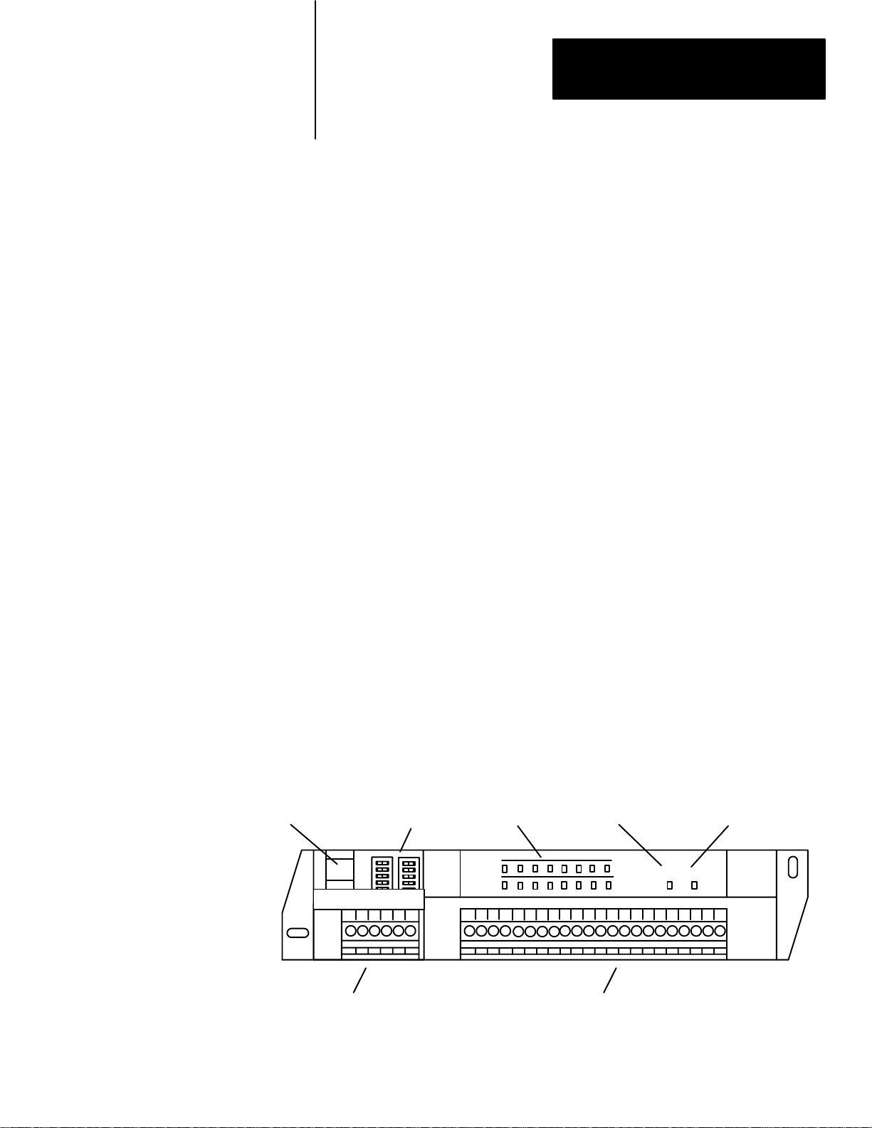
Physical features of the block I/O are shown in Figure 2.1.
Figure 2.1
Features of the Block I/O Module (1791-IOBA shown)
Major
DH-485 Port
Removable Remote I/O Link Connector
Switch Assemblies
OUTPUT
INPUT
Communication LED Power LEDStatus Indicators
COMM POWER
Removable Input/Output Connector
10825-I
21
Page 9
Chapter 2
Introducing Block I/O
Wiring Connectors – The remote I/O link connector and input/output
connector are removable for easy connection of wiring.
Switch Assemblies – Two DIP switches are provided for setting the I/O
rack number, starting I/O group, transmission rate, last chassis, last state
and DH–485 terminator.
Status Indicators – LED indicators are provided for communication,
power and input/output status. These provide a visual indication for aid in
troubleshooting.
DH–485 Port – A plug–in port is provided for use with DH–485 data link
when used with the SLC controller.
How Block I/O Fits in a PLC System
Block I/O is a complete I/O interface that includes the functionality of the
I/O rack, adapter, power supply, and I/O modules in a single unit. Simply
connect sensors and actuators to the module and use the remote I/O cable
to connect the block I/O to your programmable controller (Figure 2.4).
The block uses sinking inputs and sourcing outputs.
In sinking inputs(Figure 2.2), the dc common is bussed on the block. and
the current is sourced from the field device. The sourcing field device
switches the hot side of the power supply bus causing current to flow
through the sourcing device to the sinking input on the block.
Figure 2.2
Input Example
Sinking
+V
Field
Device
Field
Device
Block I/O
Sinking
Input
22
DC Power
Supply
-V
COM
Input Common (COM)
10826-I
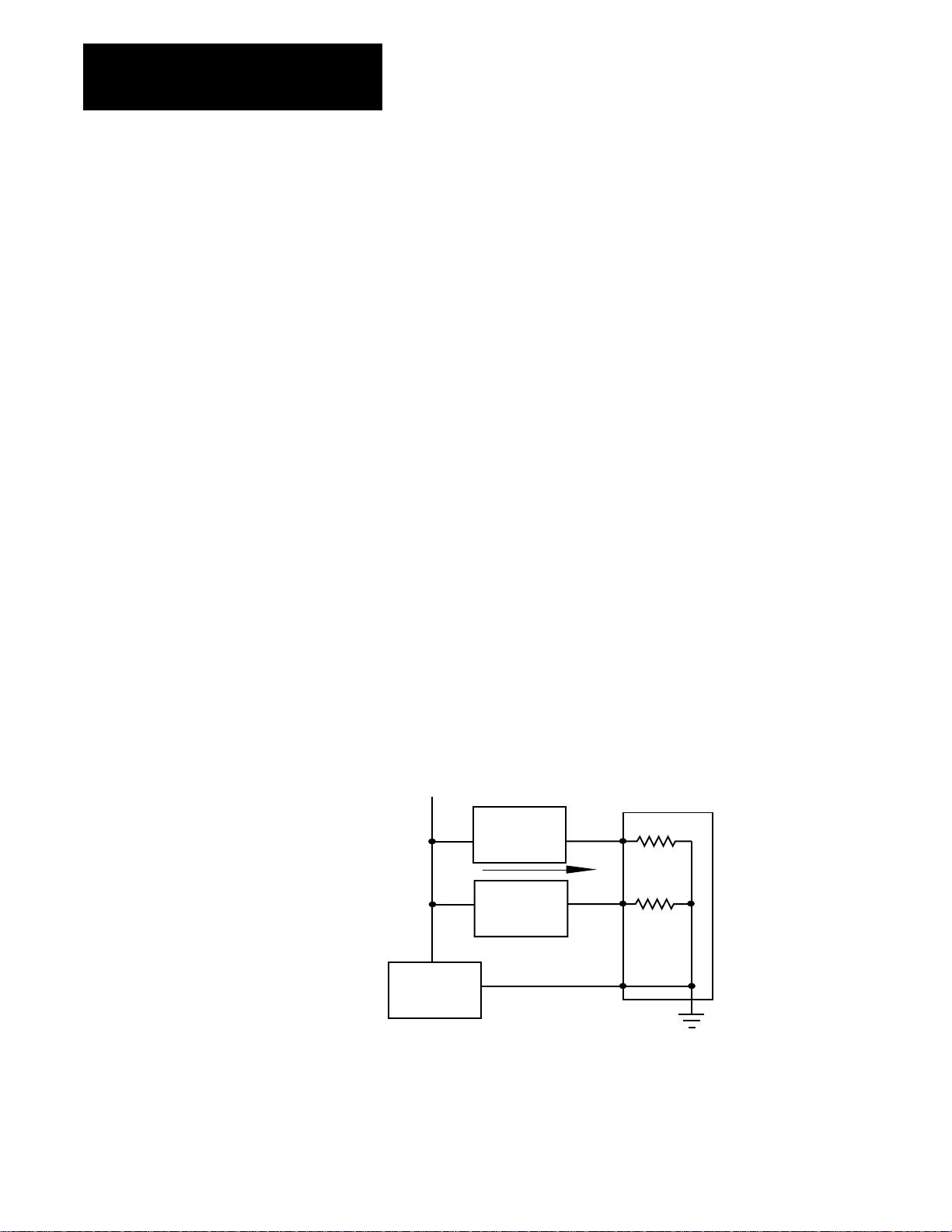
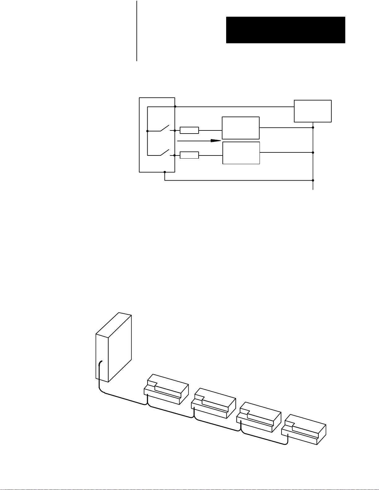
Sourcing outputs(Figure 2.3) have the power bussed in the block. When
the output is on, current is supplied to the field control device, which sinks
the current. The field circuit and the equipment remain at ground potential
until the output is turned on.
Page 10
Chapter 2
Introducing Block I/O
Figure 2.3
Sourcing
Output Example
Block I/O
GND
+V
Fuse
Fuse
Field
Device
Field
Device
Common
DC Power
Supply
-V
Bus
10827-I
You connect the block I/O to your remote I/O link as you would any other
device (Figure 2.4). The block looks like a 1/4 I/O rack to the processor,
and uses 2 words of input image table memory and 2 words of output
image table memory. The block is addressed directly on the remote I/O
link.
Programmable Controller
or Scanner
.
Block I/O functions exactly like any Allen–Bradley remote I/O product.
Input and output data is scanned asynchronously and transferred back and
forth between the block and the controller input and output image table.
Figure 2.4
I/O Connection in a PLC System
Block
Blocks are daisy-chained to
a programmable controller
or a scanner
Block I/O - each block
is 1/4 I/O rack.
.
10828-I
23
Page 11

Chapter 2
Introducing Block I/O
Summary
In this chapter you learned what block I/O is, its features and how it
functions.
24
Page 12

Installing Block I/O
1775 S4A, S4B, S5, SR
Note: PLC 5250 requires a
Chapter
3
Chapter
Objectives
Pre-installation Considerations
When using and Maximum Capacity
PLC-2 family 16 blocks with 150 ohm terminator 57.6K 10,000 cable-feet
Any scanner module
In this chapter you will learn how to mount the block, connect the remote
I/O link, connect the input and output wiring to the block, and terminate
the remote I/O link.
Before installation, you must determine:
the number of blocks desired
the total distance of the installation
transmission rate desired
if external fuses are required
Refer to Table 3.A for acceptable combinations.
Table 3.A
Acceptable
Combinations of Processor and Block I/O
Baud Rate
Used
28 blocks with 82 ohm terminator 57.6K 10,000 cable-feet
Network Distance
Maximum
PLC-3 family 16 blocks with 150 ohm terminator 57.6K 10,000 cable-feet
PLC-5 family 16 blocks with 150 ohm terminator 57.6K 10,000 cable-feet
1775S4A, S4B, S5, SR
or SR5 module
Note: PLC5250 requires a
5150RS remote scanner
TABLE CONTINUED ON NEXT PAGE
28 blocks with 82 ohm terminator 115.2K 5,000 cable-feet
32 blocks with 82 ohm terminator 57.6K 10,000 cable-feet
32 blocks with 82 ohm terminator 115.2K 5,000 cable-feet
32 blocks with 82 ohm terminator 230.4K 2,500 cable-feet
32 blocks with 82 ohm terminator 57.6K 10,000 cable-feet
32 blocks with 82 ohm terminator 115.2K 5,000 cable-feet
32 blocks with 82 ohm terminator 230.4K 2,500 cable-feet
31
Page 13

Chapter 3
Installing Block I/O
When using
SLC-5/01 Controller 1747-DSN Scanner module* 7 blocks 230.4K 2,500 cable-feet
SLC-5/02 Controller 1747-DSN Scanner module* 30 blocks 230.4K 2,500 cable-feet
SLC-5/02 Controller 1747-SN Remote I/O
Scanner Module*
* The DH-485 network, which operates independent of the RIO/DIO network, supports up to 30 DH-485 nodes (blocks or 1747-AIC
isolated couplers). The maximum DH-485 network distance is 4,000 cable-feet.
Installing the Block I/O
Mounting dimensions for the block I/O module are shown in Figure 3.1.
Maximum Capacityand
16 blocks 57.6K
Baud Rate
Used
115.2K
230.4K
Mount the blocks horizontally with a minimum of 2” between blocks. This
air gap is necessary to maintain proper cooling air flow through the block.
8mm
0.31"
Figure 3.1
Mounting
-IOBB)
Depth = 84.33mm (3.32")
Dimensions for the Block I/O Module (Cat. No. 1791-IOBA and
198mm
7.8"
Maximum
Network Distance
10,000 cable-feet
5,000 cable-feet
2,500 cable-feet
10mm
0.39"
10mm
0.39"
16mm
0.63"
OUTPUT
INPUT
180mm
7.1"
212mm
8.35"
COMMPOWER
35mm
1.37"
16mm
0.63"
10829-I
The operating temperature in the air gap between block I/O modules must
not exceed 55
o
C (151oF). The dimensions of the air gap required are
shown in Figure 3.2.
32
Page 14

Chapter 3
Installing Block I/O
Connecting Wiring
51mm
2"
Figure 3.2
Clearance
Required for Block I/O Modules
OUTPUT
INPUT
51mm
2"
51mm
2"
COMMPOWER
51mm
2"
10830-I
Connections to the block I/O module are made to the removable
connectors which plug into the front of the block. The connector blocks are
keyed to prevent incorrect insertion.
Wiring for the block is shown in Figure 3.3 and Figure 3.4. Remote I/O
link wiring connections are shown in Figure 3.5.
2SHD BACOM1
Remote
I/O Link
(see Figure 3.5)
DH-485
(for SLC
only)
Figure 3.3
and Output Connections for the 1791-IOBA
Input
1791-IOBA
8 OUTPUTS
+24DCNCGVDCO0O1O2O3O4O5 I0 I1I2 I3I4 I5I6 I7COMNC
+24V dc
dc Neutral
Chassis Ground
Output +Vdc
OUTPUT 0
OUTPUT 1
OUTPUT 2
OUTPUT 3
OUTPUT 4
OUTPUT 5
OUTPUT 6
OUTPUT 7
- 8 inputs and 8 outputs
8 INPUTS
O6O7
Input Common
INPUT 7
INPUT 6
INPUT 5
INPUT 4
INPUT 3
INPUT 2
INPUT 1
INPUT 0
10831-I
33
Page 15

Chapter 3
Installing Block I/O
2 SHD B A COM1
Remote
I/O Link
DH-485
(for SLC
only)
Figure 3.4
W
Input/Output
6 OUTPUTS
+24 DCN CGVDC O0 O1 O2 O3 O4 O5 I0 I1 I2 I3 I4 I5 I6 I7 I8 I9 COMNC
+24V dc
dc Neutral
Chassis Ground
Output +Vdc
OUTPUT 0
OUTPUT 1
OUTPUT 2
OUTPUT 3
OUTPUT 4
OUTPUT 5
iring Connections for the 1791-IOBB
Table 3.B
Block Designations
Wiring
10 INPUTS
Input Common
INPUT 9
INPUT 8
INPUT 7
INPUT 6
INPUT 5
INPUT 4
INPUT 3
INPUT 2
INPUT 1
INPUT 0
1791-IOBA 1791-IOBB
Connector Designation Description Designation Description
Remote I/O Connector 1 Blue wire - RIO 1 Blue wire - RIO
2 Clear wire - RIO 2 Clear wire - RIO
SHD Shield - RIO SHD Shield - RIO
A DH-485 A A DH-485 A
B DH-485 B B DH-485 B
COM DH-485 Common COM DH-485 Common
I/O Connector +24 +24V dc +24 +24V dc
DCN dc neutral DCN dc neutral
CG Chassis ground CG Chassis ground
VDC Output supply VDC Output supply
O0 thru O7 Output 0 thru 7 O0 thru O5 Output 0 thru 5
NC No connection NC No connection
I0 thru I7 Input 0 thru 7 I0 thru I7 Input 0 thru 9
COM Input common COM Input common
34
Page 16

Chapter 3
Installing Block I/O
Power Supply Requirements
An external 24V dc power supply is required to power the block. Total
current required to power the block is equal to 200mA plus an inrush of
5.5A for 10
µsec for each block. The supply must be able to source an
additional 100mA plus an inrush current of 400mA when a peripheral is
connected.
In addition, the external power supply should have current limiting
capabilities. The voltage range must not exceed 20.5–27.6V dc.
Wiring Requirements
Wiring cable requirements are shown in the following table.
Use Cable Type With
Remote I/O Link or DIO Link Belden 9463 PLC-2, PLC-3, PLC-5 family programmable
DH-485 Data Link Belden 9842 SLC controllers only
Input and Output wiring Up to 14AWG
Connection 1 2 SHD
Clear wire X
Blue wire X
Shield wire X
Table 3.C
Acceptable
Figure 3.5
Remote
T
W
iring Cables for Block I/O Connection
I/O Link W
ighten screw to clamp wire.
iring
Stranded with 3/64
inch insulation
Shield
Clear
controllers and SLC controllers
All
Blue
10832-I
35
Page 17

Chapter 3
Installing Block I/O
Remote I/O Link or Distributed I/O Link Wiring
To Programmable Controller
or I/O Scanner Module
Blocks must be wired in series as shown in Figure 3.6 or Figure 3.7. Do
not attempt to wire any block in parallel.
The number of blocks used depends not only on the user requirements but
also on the system used. Refer to Table 3.A for maximum block usage for
individual systems.
Figure 3.6
Series
Connection for Block I/O Using PLC-2, PLC-3 or PLC-5 Family
Programmable Controllers
1 I/O Rack
Install terminating resistor on last block.
1 I/O Rack
1 I/O Rack
1 I/O Rack
10833-I
36
Page 18

To 1747-DSN
Scanner Module
Chapter 3
Installing Block I/O
Figure 3.7
Configurations for Block I/O Using the SLC Programmable
Series
Controller
To 1747-DSN
Scanner Module
Up to 7 blocks
using SLC-5/01
Processor
1
2
29
Install terminating resis
tor
on last block.
Install terminating resis
tor
on last block.
30
Up to 30 blocks with
SLC-5/02
10834-I
37
Page 19

Chapter 3
Installing Block I/O
Termination Resistor
A termination resistor must be installed on the last block in the series.
Connect the resistor as shown in Figure 3.8. Use the resistor as identified
in Table 3.D.
Figure 3.8
Installing
Tighten screw to clamp
wires and termination resistor.
Table 3.D
Terminator
PLC-2, PLC-3, PLC-5 family,
SLC 500 family
the T
ermination Resistor
Connect termination
resistor across terminals 1
and 2
Requirements
System Terminator Resistor
Termination Resistor
150 ohm - 57.6K and 115.2K baud
82 ohm - 230.4K baud
10835-I
Extended Node Capability
38
If this is the last remote I/O adapter on the remote I/O link in a PLC
system, you must use a terminating resistor to terminate both ends of the
remote I/O link (scanner end and last block end). The size of the terminator
is determined by the system configuration.
Older configurations can use a 150 ohm resistor at both ends. With newer
devices that can support it, you can use an 82 ohm termination resistor at
both ends. The 82 ohm terminators provide ”extended node” capability
which allows you to have up to 32 physical devices on the remote I/O link.
(The number of logical racks capable of being addressed by the scanner is
not affected.)
CAUTION: Devices that are operating at 230.4K baud must
have 82 ohm terminators in place for proper operation.
Page 20

Chapter 3
Installing Block I/O
Compatibility
of 1771 I/O
Products with Extended
Node Numbers
Summary
Certain products are not compatible with extended node capabilities
obtained with the use of 82 ohm terminators. The following table lists
those products that are not compatible.
Device Series
Scanners - 1771-SN All
1772-SD All
1772-SD2 Series A
1775-SR All
1775-S4A All
1775-S4B All
Adapters - 1771-AS All
1771-ASB Series A
1771-DCM All
Miscellaneous - 1771-AF All
1771-AF1 All
In this chapter you learned how to physically mount your block I/O, make
power wiring connections, make the input/output wiring connections to
the block, and terminate the remote I/O link.
39
Page 21

Chapter
4
Configuring Your Block I/O for PLC
Family Programmable Controllers
Chapter
Setting the Configuration Switches
Objectives
In this chapter you will learn how to configure your block I/O when used
with PLC family programmable controllers. This includes the following:
setting the configuration switches
addressing the block I/O
Each block I/O module has two 6–position DIP switches for setting:
starting I/O group
I/O rack number
transmission (baud) rate
last chassis
last state
DH–485 terminator
These switches are accessible by opening the door on the left side of the
module (Figure 4.1).
41
Page 22

Chapter 4
Configuring Your Block I/O for PLC
Family Programmable Controllers
S1 S2
Figure 4.1
Settings
Switch
Starting
I/O Group
0
2
4
6
I/O Rack Number
Switches 3-6
(see Table 4.A, B and C)
Switch
12
On (Closed)
Off (Open) On (Closed)
On (Closed)Off (Open)
Off (Open) Off (Open)
On (Closed)
OUTPUT
INPUT
S1 S2
OPEN
12 3456
Switch as viewed from this end.
Off = Open
On = Closed
12 3456
OPEN
Not
Use
d
COMMPOWER
230.4K
115.2K
57.6K
Reset to 0
Hold last state
Yes
No On (Closed)
Terminate
None
On (Closed)
Off (Open) On (Closed)
On (Closed)
Off (Open)
On (Closed)
Off (Open)
Off (Open)
On (Closed)
56Baud Rate
Off (Open)
On (Closed)
4Last State
3Last Chassis
1DH-485
10836-I
42
Table 4.A
Rack Number and First I/O Group Switch Selections for PLC-2 Family
I/O
Processors
I/O Rack Switch Number
Number 3 4 5 6
1 On (Closed) On (Closed) On (Closed) On (Closed)
2 Off (Open) On (Closed) On (Closed) On (Closed)
3 On (Closed) Off (Open) On (Closed) On (Closed)
4 Off (Open) Off (Open) On (Closed) On (Closed)
5 On (Closed) On (Closed) Off (Open) On (Closed)
6 Off (Open) On (Closed) Off (Open) On (Closed)
7 On (Closed) Off (Open) Off (Open) On (Closed)
Page 23

Chapter 4
Configuring Your Block I/O for PLC
Family Programmable Controllers
Table 4.B
and PLC-5/250 I/O Rack Addressing
PLC-3
I/O Rack Switch Number I/O Rack Switch Number
Number 3 4 5 6 Number 3 4 5 6
0 On (Closed) On (Closed) On (Closed) On (Closed) 10 On (Closed) On (Closed) On (Closed) Off (Open)
1 Off (Open) On (Closed) On (Closed) On (Closed) 11 Off (Open) On (Closed) On (Closed) Off (Open)
2 On (Closed) Off (Open) On (Closed) On (Closed) 12 On (Closed) Off (Open) On (Closed) Off (Open)
3 Off (Open) Off (Open) On (Closed) On (Closed) 13 Off (Open) Off (Open) On (Closed) Off (Open)
4 On (Closed) On (Closed) Off (Open) On (Closed) 14 On (Closed) On (Closed) Off (Open) Off (Open)
5 Off (Open) On (Closed) Off (Open) On (Closed) 15 Off (Open) On (Closed) Off (Open) Off (Open)
6 On (Closed) Off (Open) Off (Open) On (Closed) 16 On (Closed) Off (Open) Off (Open) Off (Open)
7 Off (Open) Off (Open) Off (Open) On (Closed) 17 Off (Open) Off (Open) Off (Open) Off (Open)
Table 4.C
I/O Rack Addressing
PLC-5
I/O Rack Switch Number I/O Rack Switch Number
Number 3 4 5 6 Number 3 4 5 6
01 Off (Open) On (Closed) On (Closed) On (Closed) 10 On (Closed) On (Closed) On (Closed) Off (Open)
02 On (Closed) Off (Open) On (Closed) On (Closed) 11 Off (Open) On (Closed) On (Closed) Off (Open)
03 Off (Open) Off (Open) On (Closed) On (Closed) 12 On (Closed) Off (Open) On (Closed) Off (Open)
PLC-5/15 processors can scan racks 01-03 13 Off (Open) Off (Open) On (Closed) Off (Open)
04 On (Closed) On (Closed) Off (Open) On (Closed) 14 On (Closed) On (Closed) Off (Open) Off (Open)
05 Off (Open) On (Closed) Off (Open) On (Closed) 15 Off (Open) On (Closed) Off (Open) Off (Open)
06 On (Closed) Off (Open) Off (Open) On (Closed) 16 On (Closed) Off (Open) Off (Open) Off (Open)
07 Off (Open) Off (Open) Off (Open) On (Closed) 17 Off (Open) Off (Open) Off (Open) Off (Open)
PLC-5/25 processors can scan racks 01-07 PLC-5/40 and 5/60 processors can scan racks 01-17
Each block uses 2 words of output image table memory and 2 words of
input image table memory. Each block occupies 1/4 rack of data table, with
4 blocks comprising 1 logical rack. Image table usage for one assigned
rack number is shown in Figure 4.2 (IOBA) and Figure 4.4 (IOBB). An
example of image table usage is shown in Figure 4.3 (IOBA) and
Figure 4.5 (IOBB).
43
Page 24

Chapter 4
Configuring Your Block I/O for PLC
Family Programmable Controllers
Figure 4.2
Image T
I/O
able for One Assigned Rack Number with 1791-IOBA
Input Image
710
0
1
2
3
4
5
6
7
Reserved
Reserved
Reserved
Reserved
Reserved
Reserved
Reserved
Reserved
017
Figure 4.3
T
able Usage Example for One Starting I/O Group with 1791-IOBA
Input
Example
T
ype of I/O
1 = Input
0 = Output
I/O Rack Number
1791-IOBA1791-IOBA1791-IOBA1791-IOBA
11000
Rack 1
0
1
2
3
4
5
6
7
For 1791-IOBA - 7-0 input and 7-0 output image bits
Reserved
Reserved
Reserved
Reserved
Output Image
710
Reserved
Reserved
Reserved
Reserved
017
I/O Bit
I/O Group Number
10837-I
44
Starting
I/O Group
0
110
111
010
011
Reserved
Reserved
Reserved
11107654321
Block Data
Reserved
11 10
7654321
Block Data
0
0
Input
Image
Output Image
10838-I
Page 25

Figure 4.4
I/O Image T
Chapter 4
Configuring Your Block I/O for PLC
Family Programmable Controllers
able for One Assigned Rack Number with 1791-IOBB
Input Image
710
0
1
2
3
4
5
6
7
Reserved
Reserved
Reserved
Reserved
Reserved
Reserved
Reserved
Reserved
017
Figure 4.5
Input
Example
Type
of I/O
1 = Input
0 = Output
I/O Rack Number
1791-IOBB1791-IOBB1791-IOBB1791-IOBB
T
able Usage Example for One Starting I/O Group with 1791-IOBB
1 I/O Rack
0
1
2
3
4
5
6
7
For 1791-IOBB - 11-0 input and 5-0 output image bits
Output Image
710
Reserved
Reserved
Reserved
Reserved
Reserved
Reserved
Reserved
Reserved
11200
I/O Bit
I/O Group Number
017
Starting
Group
I/O
112
113
012
2
013
Reserved
Reserved
Reserved
11107654321
Block Data
Reserved
11 10 7 6
54321
Block Data
0
0
Input Image
Output Image
45
Page 26

Chapter 4
Configuring Your Block I/O for PLC
Family Programmable Controllers
Summary
In this chapter you learned how to set the configuration switches and
address the block I/O. You also learned about input and output image use
in memory.
46
Page 27

Chapter
5
Configuring Your Block I/O for SLC
Controllers
Chapter
Setting the Configuration Switches
Objectives
In this chapter you will learn to identify block I/O switches and their
position.
Refer to publication 1747–ND012, Distributed I/O Scanner and Block, for
complete information on switch settings and addressing of the block I/O.
Each block I/O module has two 6–position DIP switches for setting:
block address
transmission (baud) rate
last state or reset
DH–485 termination
These switches are accessible by opening the door on the left side of the
module (Figure 5.1).
51
Page 28

Chapter 5
Configuring Your Block I/O for
SLC Controllers
S1 S2
Figure 5.1
Settings for Block I/O when used with the SLC 500 Controller
Switch
Block
Addresses
1-7
1-15
17-31
Switches
1 - 6
100000 to 111000
100000 to 111100
100010 to 111110
OUTPUT
INPUT
S1 S2
OPEN
12 3456
Switch as viewed from this end.
Off = Open = 1
12 3456
OPEN
Not Used
COMM POWER
230.4K
Reset to 0
Hold last state
Terminate
None
56Baud Rate
On (0)
4Hold Last State
Off (1)
On (0)
1DH-485
On (0)
Off (1)
Off (1)
52
On = Closed = 0
10839-I
Page 29

Chapter 5
Configuring Your Block I/O for
SLC Controllers
Table 5.A
Addresses for Block I/O Used with SLC 500 Controllers
Block
Block Switch S1 Positions Block Switch S1 Positions
Address 1 2 3 4 5 6 Address 1 2 3 4 5 6
1 Off (1) On (0) On (0) On (0) On (0) On (0) 17 Off (1) On (0) On (0) On (0) Off (1) On (0)
2 On (0) Off (1) On (0) On (0) On (0) On (0) 18 On (0) Off (1) On (0) On (0) Off (1) On (0)
3 Off (1) Off (1) On (0) On (0) On (0) On (0) 19 Off (1) Off (1) On (0) On (0) Off (1) On (0)
4 On (0) On (0) Off (1) On (0) On (0) On (0) 20 On (0) On (0) Off (1) On (0) Off (1) On (0)
5 Off (1) On (0) Off (1) On (0) On (0) On (0) 21 Off (1) On (0) Off (1) On (0) Off (1) On (0)
6 On (0) Off (1) Off (1) On (0) On (0) On (0) 22 On (0) Off (1) Off (1) On (0) Off (1) On (0)
7 Off (1) Off (1) Off (1) On (0) On (0) On (0) 23 Off (1) Off (1) Off (1) On (0) Off (1) On (0)
8 On (0) On (0) On (0) Off (1) On (0) On (0) 24 On (0) On (0) On (0) Off (1) Off (1) On (0)
9 Off (1) On (0) On (0) Off (1) On (0) On (0) 25 Off (1) On (0) On (0) Off (1) Off (1) On (0)
10 On (0) Off (1) On (0) Off (1) On (0) On (0) 26 On (0) Off (1) On (0) Off (1) Off (1) On (0)
11 Off (1) Off (1) On (0) Off (1) On (0) On (0) 27 Off (1) Off (1) On (0) Off (1) Off (1) On (0)
12 On (0) On (0) Off (1) Off (1) On (0) On (0) 28 On (0) On (0) Off (1) Off (1) Off (1) On (0)
13 Off (1) On (0) Off (1) Off (1) On (0) On (0) 29 Off (1) On (0) Off (1) Off (1) Off (1) On (0)
14 On (0) Off (1) Off (1) Off (1) On (0) On (0) 30 On (0) Off (1) Off (1) Off (1) Off (1) On (0)
15 Off (1) Off (1) Off (1) Off (1) On (0) On (0) 31 Off (1) Off (1) Off (1) Off (1) Off (1) On (0)
16 Invalid
Addressing the Blocks Using SLC Controllers
The SLC controller communicates with the block I/O using a Distributed
I/O Scanner module (cat. no. 1747–DSN). The scanner can address up to 7
blocks using an SLC 5/01 Controller, and up to 30 blocks using an SLC
5/02 Controller. When used with the Distributed I/O Scanner module,
block addresses must be contiguous. The actual number of blocks to which
the scanner module will communicate is determined when programming
the SLC controller.
Refer to the 1747–DSN Scanner module user’s manual for more
information.
Summary
In this chapter you learned how to identify and set the configuration
switches on the block.
53
Page 30

Troubleshooting
Chapter
6
Chapter Objectives
LED Indicators
In this chapter you will learn about the LED indicators on the block I/O
module, and how to use them to troubleshoot the unit.
Each block I/O module has LED indicators (Figure 6.1) which provide
indication of specific functions. Each module has the following:
green communication indicator – indicates whether communication is
occurring between processor or scanner and the block.
red power indicator – indicates if power is applied to module and
internal hardware status
16 I/O status indicators (8 input–8 output or 10 input–6 output) – reflect
the state of the individual inputs and outputs (on or off)
The location of the indicators is shown in Figure 6.1. Refer to Table 6.A
for status indications reported by the indicators.
Figure 6.1
Indicators
on the Block I/O Module (1791-IOBA shown)
Communication LED (green)Power LED (red)Status Indicators
OUTPUT
INPUT
COMMPOWER
10846-I
61
Page 31

Chapter 6
Troubleshooting
Table 6.A
Troubleshooting
Indication Probable Cause Corrective Action
Green COMM LED on
Red POWER LED on
I/O status LED on/off
Red POWER LED flashing Block failed self-test, or a major fault is detected. Cycle power to the block. If problem persists,
Red POWER LED off No 24V dc power connected, or hardware fault. Check 24V dc power to block
Green COMM LED off No communication with processor, scanner etc. Check that power LED is on. Make sure that
Green COMM LED flashing Reset command (or output disable bit for SLC) has
Summary
Normal indication None required
been issued by processor or scanner.
SLC or programmable controller not in run mode. Place in run mode.
In this chapter you learned about the LED indicators and how to use them
Chart
replace the block.
proper number of blocks are configured.
Check program. Correct as necessary.
to troubleshoot the block I/O module.
62
Page 32

Specifications
General Specifications
Appendix
A
External power
Environmental Conditions
Operating Temperature
Storage Temperature
Relative Humidity
Conductors Wire Size 14 gauge stranded (maximum)
Power Dissipation IOBA: 13.42 Watts (maximum); 9.46 Watts (typical)
Thermal Dissipation IOBA: 45.9 BTU/hr (maximum); 32.4 BTU/hr (typical)
Remote I/O Isolation 850V dc (transformer) for 1 second
DH-485 Isolation 850V dc (optocoupler) for 1 second
Interconnect cable length RIO: PLC 57.6K 10,000 cable-feet
Cable requirements RIO/DIO - Belden 9463
1791-IOBA Input Specifications
200mA @ 24V dc; initial surge 5.5A for 10µsec
32 to 131oF (0 to 55oC)
-40 to 185
5 to 95% noncondensing
3/64 inch insulation (maximum)
IOBB: 12.39 Watts (maximum); 8.73 Watts (typical)
IOBB: 42.4 BTU/hr (maximum); 29.8 BTU/hr (typical)
DH-485 4000 ft (1219 meters)
DH-485 - Belden 9842
o
F (-40 to 85oC)
115.2K 5,000 cable-feet
230.4K 2,500 cable-feet
SLC 230.4K 2,500 cable-feet
Number of Inputs 8
Input type Sinking
Input voltage range 20.5 to 27.6V dc
On-state input current 6.3mA (minimum)
On-state input voltage 20.5V dc (minimum)
Off-state voltage 5.1V dc (maximum)
Off-state current 1mA dc (maximum)
Turn On time 1.5msec (maximum)
Turn Off time 1.0msec (maximum)
A1
Page 33

Appendix A
Specifications
1791-IOBA Output Specifications
Number of outputs 8
Output type Source
Rated output voltage 10 to 30V dc
Maximum on-state voltage drop 1.5V dc @ 25oC
Maximum on-state current 0.5A
Minimum on-state current 15mA
Surge Current 3.0A for 10ms (maximum), 1 pulse per second max.
Off-state voltage 30V dc (maximum)
Off-state leakage current 0.5mA (maximum)
Turn on time 0.5ms (maximum)
Turn off time 1ms (maximum)
1791-IOBB Input Specifications
Number of Inputs 10
Input type Sinking
Input voltage 20.5 to 27.6V dc
On-state input voltage 20.5V dc (minimum)
On-state input current 6.3mA (minimum)
Off-state voltage 5.1V dc
Off-state current 1mA dc
Turn On time 1.5msec (maximum)
Turn Off time 1.0msec (maximum)
A2
Page 34

Appendix A
Specifications
1791-IOBB Output Specifications
Number of outputs 6
Output type Source
Rated output voltage 10 to 30V dc
Maximum on-state voltage drop 1.5V dc @ 25oC
Maximum on-state current 0.5A
Minimum on-state current 15mA
Surge Current (maximum) 3.0A for 10ms (max), 1 pulse per second max.
Off-state voltage 30V dc (maximum)
Off-state leakage current 0.5mA (maximum)
Turn on time 0.5ms (maximum)
Turn off time 1ms (maximum)
A3
Page 35

Index
B
block addressing, SLC, 53
C
combinations, acceptable processor and
block I/O, 31
compatibility, extended node numbers, 39
configuration switches, 41
SLC, 51
connecting block I/O, in a PLC system, 23
connecting wiring, 33
1791-IOBA, 33
1791-IOBB, 34
D
description, 21
DH-485 port, 22
E
extended node capability, 38
F
M
mounting dimensions, 32
P
power supply requirements, 35
R
related publications, 12
remote I/O link connector, 22
remote I/O link wiring, 36
S
series connections
PLC-2, PLC-3 and PLC-5, 36
SLC, 37
sinking inputs, 22
description, 22
sourcing outputs, 22
description, 22
specifications, A1
status indicators, 22
switch assemblies, 22
features, 21
I
I/O rack addressing
PLC-2 family, 42
PLC-3 and PLC-5/250, 43
PLC-5, 43
image table usage, 43
1791-IOBA, 44
1791-IOBB, 45
L
LED indicators, 61
T
termination resistor, 38
troubleshooting chart, 62
types of block I/O, 21
W
wiring cable, 35
wiring connections, definitions, 34
Page 36

With offices in major cities worldwide
WORLD
HEADQUARTERS
Allen-Bradley
1201 South Second Street
Milwaukee, WI 53204 USA
Tel: (414) 382-2000
Telex: 43 11 016
FAX: (414) 382-4444
EUROPE/MIDDLE
EAST/AFRICA
HEADQUARTERS
Allen-Bradley Europa B.V.
Amsterdamseweg 15
1422 AC Uithoorn
The Netherlands
Tel: (31) 2975/60611
Telex: (844) 18042
FAX: (31) 2975/60222
As a subsidiary of Rockwell International, one of the world’s largest technology
companies — Allen-Bradley meets today’s challenges of industrial automation with over
85 years of practical plant-floor experience. More than 13,000 employees throughout the
world design, manufacture and apply a wide range of control and automation products
and supporting services to help our customers continuously improve quality, productivity
and time to market. These products and services not only control individual machines but
integrate the manufacturing process, while providing access to vital plant floor data that
can be used to support decision-making throughout the enterprise.
ASIA/PACIFIC
HEADQUARTERS
Allen-Bradley (Hong Kong)
Limited
Room 1006, Block B, Sea
View Estate
28 Watson Road
Hong Kong
Tel: (852) 887-4788
Telex: (780) 64347
CANADA
HEADQUARTERS
Allen-Bradley Canada
Limited
135 Dundas Street
Cambridge, Ontario N1R
5X1
Canada
Tel: (519) 623-1810
FAX: (519) 623-8930
LATIN AMERICA
HEADQUARTERS
Allen-Bradley
1201 South Second Street
Milwaukee, WI 53204 USA
Tel: (414) 382-2000
Telex: 43 11 016
FAX: (414) 382-2400
FAX: (852) 510-9436
Publication 1791–6.5.1 – November 1991
Supersedes publication 1791–6.5.1 – August 1991 and 1791–6.5.1–DU1 – July 1991
Copyright 1991 Allen-Bradley Company, Inc. Printed in USA
P/N 955110–93
 Loading...