

Page 1
Block I/O
Cat. No. 1791IOBW and IOVW
User Manual
Page 2
Important User Information
Because of the variety of uses for the products described in this
publication, those responsible for the application and use of this control
equipment must satisfy themselves that all necessary steps have been taken
to assure that each application and use meets all performance and safety
requirements, including any applicable laws, regulations, codes
and standards.
The illustrations, charts, sample programs and layout examples shown in
this guide are intended solely for example. Since there are many variables
and requirements associated with any particular installation, Allen-Bradley
does not assume responsibility or liability (to include intellectual property
liability) for actual use based upon the examples shown in this publication.
Allen-Bradley publication SGI–1.1, “Safety Guidelines For The
Application, Installation and Maintenance of Solid State Control”
(available from your local Allen-Bradley office) describes some important
differences between solid-state equipment and electromechanical devices
which should be taken into consideration when applying products such as
those described in this publication.
Reproduction of the contents of this copyrighted publication, in whole or
in part, without written permission of Allen–Bradley Company, Inc.
is prohibited.
Throughout this manual we make notes to alert you to possible injury to
people or damage to equipment under specific circumstances.
ATTENTION: Tells readers where people may be hurt if
procedures are not followed properly.
ATTENTION: Tells readers where machinery may be damaged
or economic loss can occur if procedures are not
followed properly.
Attention helps you:
Identify a hazard.
Avoid the hazard.
Recognize the consequences.
Important: We recommend you frequently backup your application
programs on appropriate storage medium to avoid possible data loss.
Page 3

Table of Contents
Using This Manual P1. . . . . . . . . . . . . . . . . . . . . . . . . . . . . . .
Purpose
Audience P1
Vocabulary P1
Manual Organization P1
About
of Manual
. . . . . . . . . . . . . . . . . . . . . . . . . . . . . . . . . . . . . . . . . .
. . . . . . . . . . . . . . . . . . . . . . . . . . . . . . . . . . . . . . . .
. . . . . . . . . . . . . . . . . . . . . . . . . . . . . . . . .
Block I/O
P1. . . . . . . . . . . . . . . . . . . . . . . . . . . . . . . . . . .
P2. . . . . . . . . . . . . . . . . . . . . . . . . . . . . . . . . . . . .
Introducing Block I/O 11. . . . . . . . . . . . . . . . . . . . . . . . . . . . .
Chapter
General Description 11
How
Objectives
. . . . . . . . . . . . . . . . . . . . . . . . . . . . . . . . . .
the Block I/O Fits in a PLC System
11. . . . . . . . . . . . . . . . . . . . . . . . . . . . . . . . . . .
13. . . . . . . . . . . . . . . . . . . .
Installing Block I/O 21. . . . . . . . . . . . . . . . . . . . . . . . . . . . . . .
Chapter
Preinstallation Considerations 21
Installing
Connecting Wiring 23
Remote I/O Link Wiring 29
Extended
Compatibility of 1771 I/O Products with Extended Node Operation 211
Objectives
the Block I/O
. . . . . . . . . . . . . . . . . . . . . . . . . . . . . . . . . . .
Node Capability
21. . . . . . . . . . . . . . . . . . . . . . . . . . . . . . . . . . .
. . . . . . . . . . . . . . . . . . . . . . . . . .
22. . . . . . . . . . . . . . . . . . . . . . . . . . . . . . . .
. . . . . . . . . . . . . . . . . . . . . . . . . . . . . . . .
210. . . . . . . . . . . . . . . . . . . . . . . . . . . . . .
.
Configuring Your Block I/O 31. . . . . . . . . . . . . . . . . . . . . . . .
Chapter
Setting
Objectives
the Configuration Switches
31. . . . . . . . . . . . . . . . . . . . . . . . . . . . . . . . . . .
31. . . . . . . . . . . . . . . . . . . . . . . .
Troubleshooting 41. . . . . . . . . . . . . . . . . . . . . . . . . . . . . . . .
Chapter
Indicators 41
Replacing a Fuse 43
Summary 44
Objectives
. . . . . . . . . . . . . . . . . . . . . . . . . . . . . . . . . . . . . . . . .
. . . . . . . . . . . . . . . . . . . . . . . . . . . . . . . . . . . .
. . . . . . . . . . . . . . . . . . . . . . . . . . . . . . . . . . . . . . . . .
41. . . . . . . . . . . . . . . . . . . . . . . . . . . . . . . . . . .
Specifications A1. . . . . . . . . . . . . . . . . . . . . . . . . . . . . . . . . .
Page 4

Using This Manual
Preface
Purpose
of Manual
Audience
Vocabulary
Manual Organization
This manual shows you how to use your block I/O with an Allen–Bradley
programmable controller. It helps you install, program and troubleshoot
your module.
You must be able to program and operate an Allen–Bradley programmable
controller (PLC) to make efficient use of block I/O modules.
We assume that you know how to do this in this manual. If you do not,
refer to the appropriate PLC programming and operations manual before
you attempt to program this module.
In this manual, we refer to:
the block I/O module as the “block” or the “module”
the programmable controller as the “controller”
This manual is divided into 4 chapters. The following chart shows each
chapter with its corresponding title and brief overview of the topics
covered in that chapter.
Chapter Title Topics Covered
1 Introducing Block I/O
2 Installing Block I/O
3
4 Troubleshooting
Appendix A Specifications Specifications for the block I/O.
Configuring Your Block I/O for PLC
Family Programmable Controllers
Description of the modules, including general and
hardware features
Module power requirements, location, and wiring
information
How to set the configuration switches and address
the block I/O.
How to use the indicators to troubleshoot your block
I/O module.
P-1
Page 5

Preface
Using This Manual
About
Block I/O
Related Publications
Block I/O consists of small, self–contained remote I/O devices complete
with power supply, programmable controller interface, input/output
connections and signal conditioning circuitry.
This publication covers the 1791–IOBW and –IOVW block I/O modules.
The 1791–IOBW has 32 sinking inputs and 32 sourcing outputs; the
1791–IOVW has 32 sourcing inputs and 32 sinking outputs. In all other
aspects, they are identical.
For a list of publications with information on Allen–Bradley
programmable controller products, consult our publication index (SD499).
P-2
Page 6

Introducing Block I/O
Chapter
1
Chapter
Objectives
General Description
In this chapter you will learn what block I/O is, its features, and how
it functions.
Block I/O consists of small, self-contained remote I/O devices complete
with power supply, programmable controller interface, input/output
connections and signal conditioning circuitry.
The 1791-IOBW 24V dc module has 32 sink input channels, and 32 source
output channels.
The 1791-IOVW 24V dc module has 32 source input channels, and 32 sink
output channels.
Complete specifications for these modules are contained in Appendix A.
The blocks are compatible with PLC-2
programmable controllers, and the SLC 500
used with PLC-2 family programmable controllers, a sub-scanner module
is used to communicate with the blocks. When used with PLC-3 and
PLC-5 family programmable controllers, they can be connected directly to
the controller or to a scanner module. When used with SLC 500
controllers, a 1747-SN remote I/O scanner is used to communicate with the
blocks.
, PLC-3, and PLC-5 family
modular controllers. When
ATTENTION: However, when using PLC-3 programmable
controllers, you must use a 1775-S5 or -SR5 scanner module.
Do not use 1775-SR, -S4A or -S4B scanner modules.
Note: The 1791-IOBW and -IOVW block modules are not compatible
with the 1747-DSN scanner module.
Connections are made to removable terminal blocks mounted on the sides
of the block.
Figure 1.1 shows the physical features of the block I/O.
1-1
Page 7
Chapter 1
Introducing Block I/O
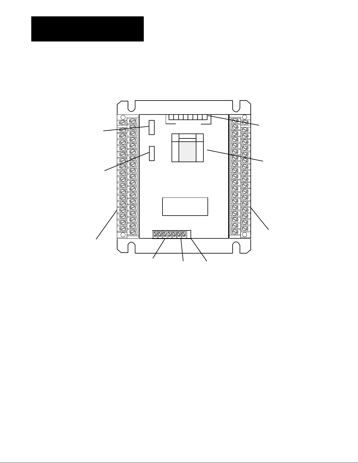
Figure 1.1
Features of the 1791IOBW and IOVW Block I/O Modules
Major
(IOBW shown)
Rack Address
Switch
Power, Active,
Comm and Fuse
LED Indicators
Removable
Input Terminal
Blocks
RACK
ADDR
87654321
CONFIGURATION
SWITCHES
POWER
ACTIVE
COMM
FUSE
1791IOBW
64 POINT
24V DC DISTRIBUTED
I/O MODULE
CONFIGURATION SWITCHES
Configuration Switches
(on top of unit)
Input/Output
Status LED
Array
Removable
Output Terminal
Blocks
RIO Wiring Block
+24V dc Power
Termination
Resistor
Switch
10914I
Wiring Terminals - The remote I/O field wiring is made to two separate
removable 37-pin terminal blocks mounted on the sides of the module.
Terminal assignments are shown in chapter 2.
1-2
A separate nonremovable terminal block is provided for connection of the
remote I/O link and external 24V dc power supply.
Switch Assemblies - Two DIP switches are provided for setting the I/O
configuration and rack address.
The configuration switch lets you select baud rate, last state, processor
restart lockout, last rack and I/O group.
The rack address switch lets you select the system rack address for
the block.
A third switch is provided for selection of the built-in termination resistor.
Page 8

Chapter 1
Introducing Block I/O
Status Indicators - Bi-color LED indicators provide power, active,
communication and fuse blown indications. An LED array provides
input/output status.
Indicator Indication
How the Block I/O Fits in a
PLC System
Power(green/wht)
Power (green/wht)
Active(green/red)
Active (green/red)
Comm(green/wht)
Comm (green/wht)
Fuse(red/wht)
Fuse (red/wht)
On (green) Customer voltage is present
Off (wht)
On (green) CPU operating correctly
Off (red)
On (green) Communication correctly established
Off (wht)
On (red) One of the fuses is open
Off (wht) Both fuses are intact
No customer voltage
CPU not running
Communication not established
The I/O status array is an 8 by 8 array of 64 LEDs capable of displaying
the status of 32 inputs and 32 outputs at any one time.
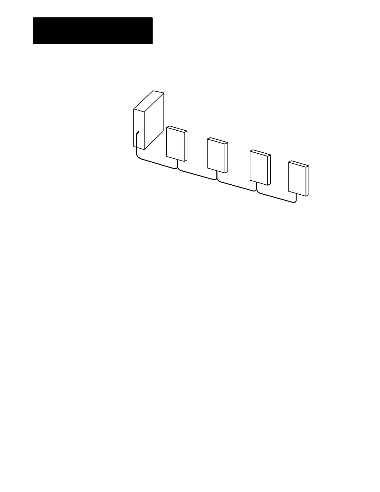
Block I/O is a complete I/O interface that includes the functionality of the
I/O rack, adapter, power supply, and I/O modules in a single unit. Simply
connect sensors and actuators to the module and use the remote I/O cable
to connect the block I/O to your programmable controller (Figure 1.6).
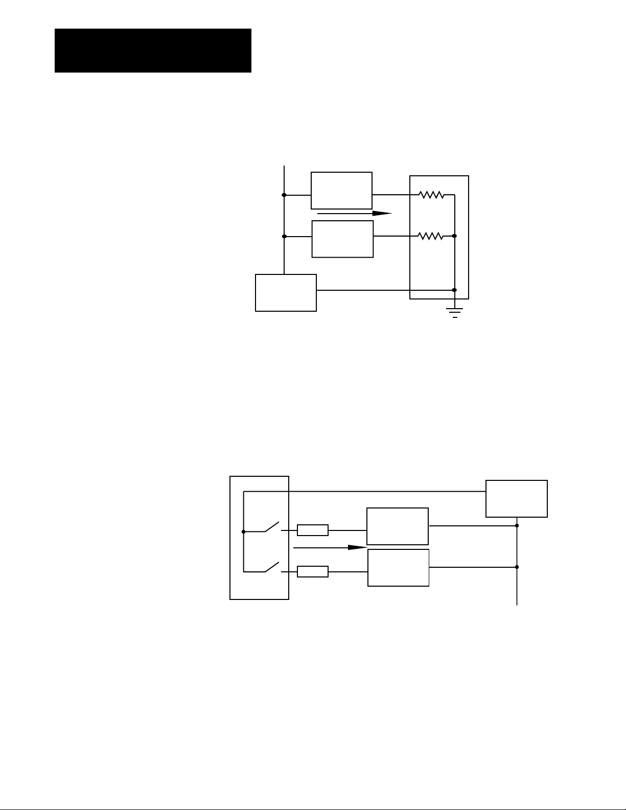
The 1791-IOBW block uses sinking inputs and sourcing outputs.
In sinking inputs, the dc common is bussed on the block. and the current is
sourced from the field device. The sourcing field device switches the hot
side of the power supply bus causing current to flow through the sourcing
device to the sinking input on the block. Refer to Figure 1.2.
1-3
Page 9
Chapter 1
Introducing Block I/O
Figure 1.2
Input Example
Sinking
+V
dc Power
Supply
Field
Device
Field
Device
V
Block I/O
Sinking
Input
10826I
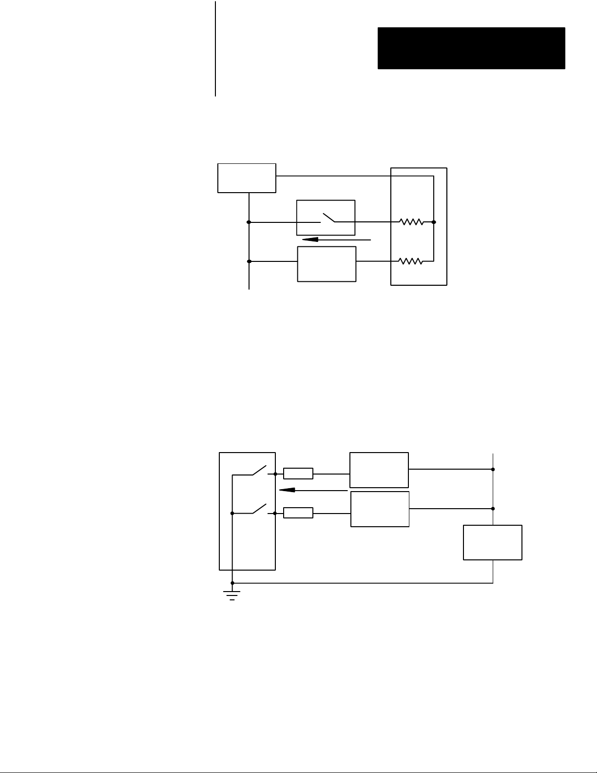
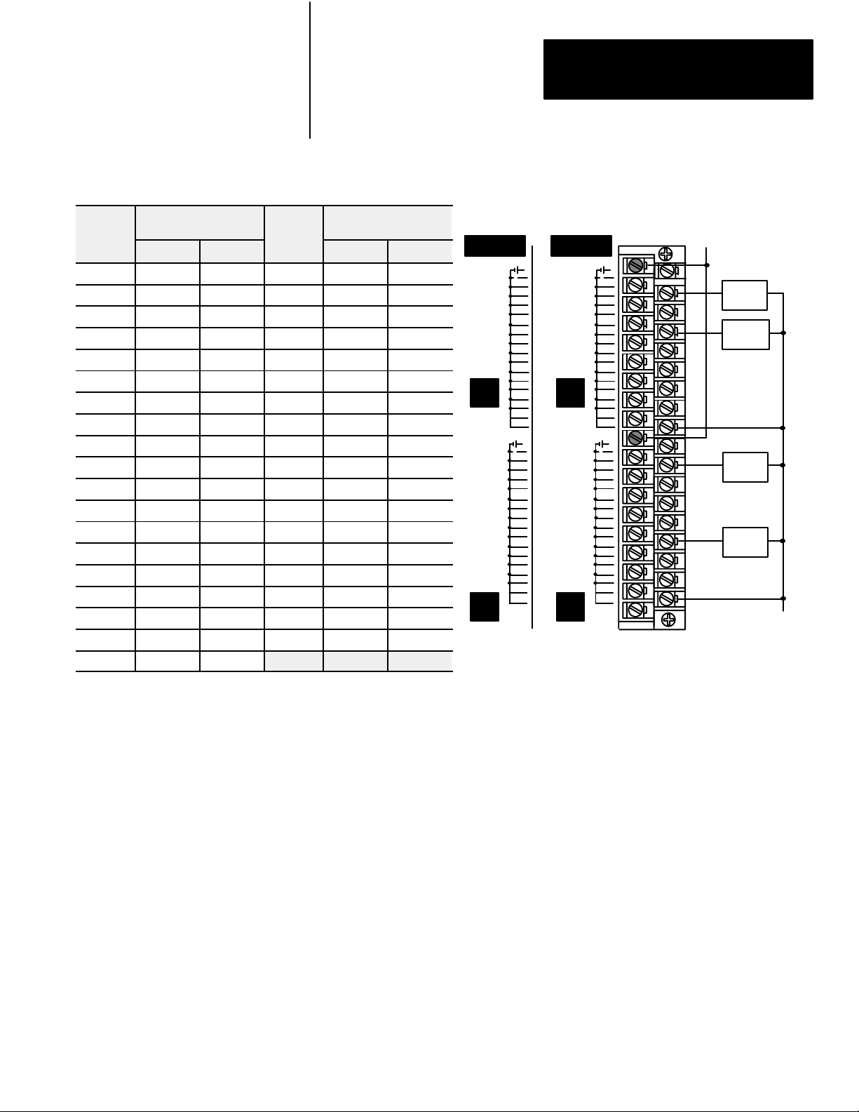
Sourcing outputs have the power bussed in the block. When the output is
on, current is supplied to the field control device, which sinks the current.
The field circuit and the equipment remain at ground potential until the
output is turned on. Refer to Figure 1.3.
Figure 1.3
Sourcing
Output Example
Block I/O
+V
Fuse
Fuse
Field
Device
Field
Device
dc Power
Supply
V
Bus
10827I
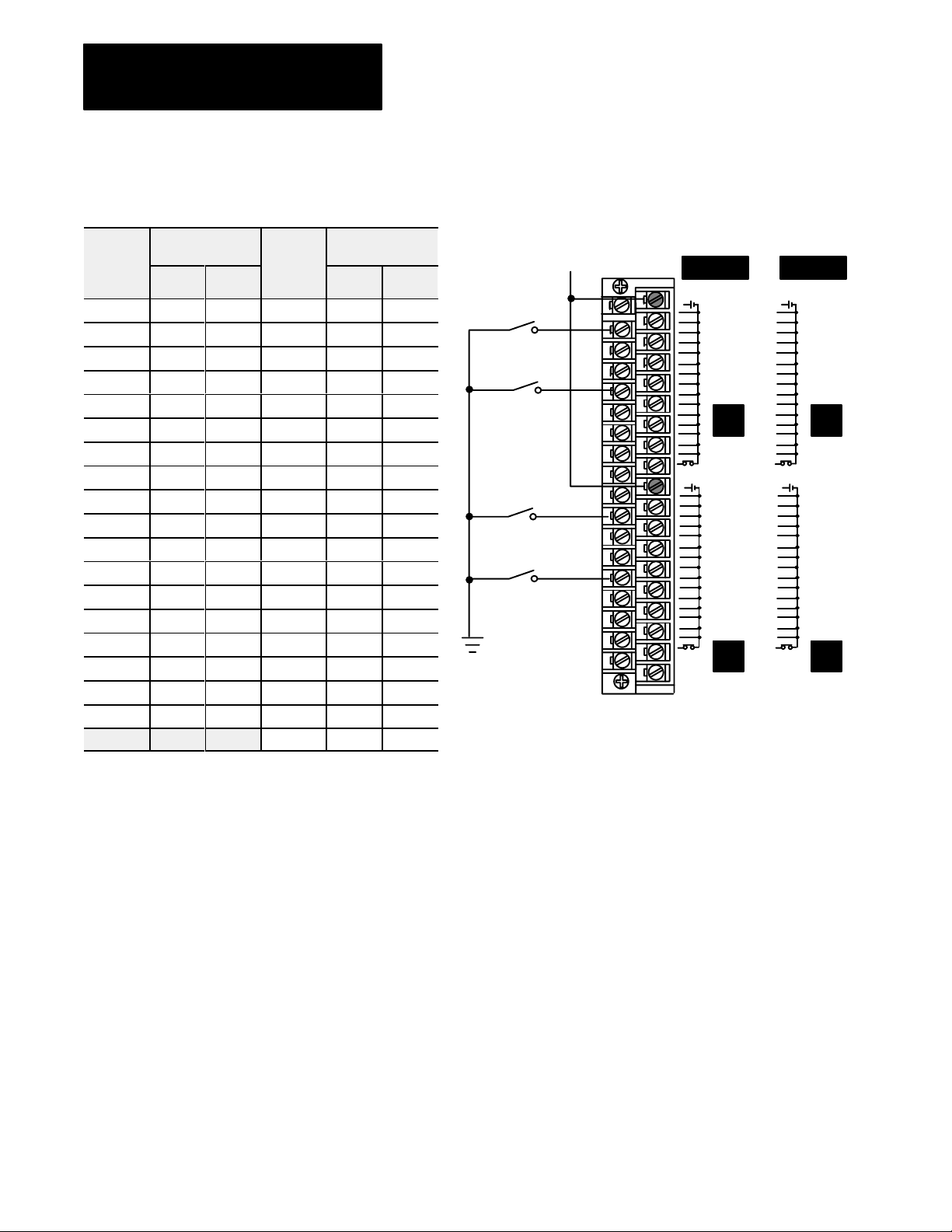
The 1791-IOVW block uses sourcing inputs and sinking outputs.
In sourcing input modules (Figure 1.4), the +V on dc circuits is bussed on
the module supplying (sourcing) the current for each input circuit. The
field device switches the circuit to the common (side of the power supply,
sinking the circuit and causing current to flow from the module’s input
1-4
Page 10
Chapter 1
Introducing Block I/O
Figure 1.4
dc Power
Supply
V
Input Example
Field
Device
+V
Block
Input
I/O
10917I
Sourcing
dc Common Bus
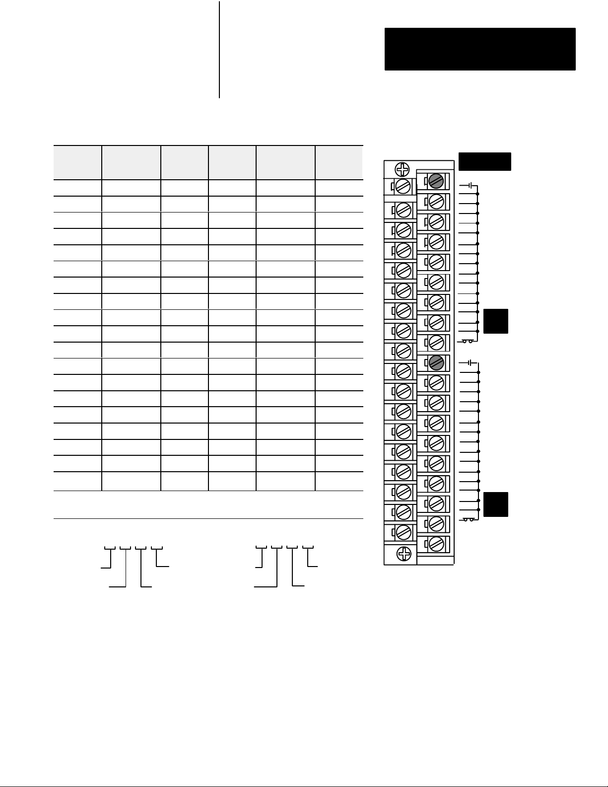
In sinking outputs (Figure 1.5), the current flow is reversed. The dc
common is bussed on the module and the current is sourced from the field
device being actuated. When an output is turned on, the output switch in
the module sinks the circuit, causing current to flow from the +V bus
through the field device to the module.
Figure 1.5
Output Example
Sinking
Block I/O
Fuse
Fuse
Field
Device
Field
Device
Common
+V
Bus
dc Power
Supply
V
10918I
Block I/O functions exactly like any Allen-Bradley remote I/O product.
Input and output data is scanned asynchronously and transferred back and
forth between the block and the controller input and output image table.
You connect the block I/O to your remote I/O link as you would any other
device. The block looks like a 1/4 I/O rack to the processor, and uses 2
words of input image table memory and 2 words of output image table
memory. The block is addressed directly on the remote I/O link.
1-5
Page 11
Chapter 1
Introducing Block I/O
Programmable Controller
or Scanner
Figure 1.6
I/O Connection in a PLC System
Block
Block I/O each block
is 1/4 I/O rack.
Blocks are daisychained to a
programmable controller or scanner.
10915I
1-6
Page 12

Installing Block I/O
Chapter
2
Chapter
Preinstallation
Considerations
Objectives
In this chapter you will learn how to mount the block, how to connect the
remote I/O link, how to connect the input and output wiring to the block,
and how to terminate the remote I/O link.
Before installation, you must determine:
the number of blocks desired
the total distance of the installation
transmission rate desired
2-1
Page 13
Chapter 2
Installing Block I/O
Installing the Block I/O
Inches
(Millimeters)
0.67
(17.105)
6.54
(166.0)
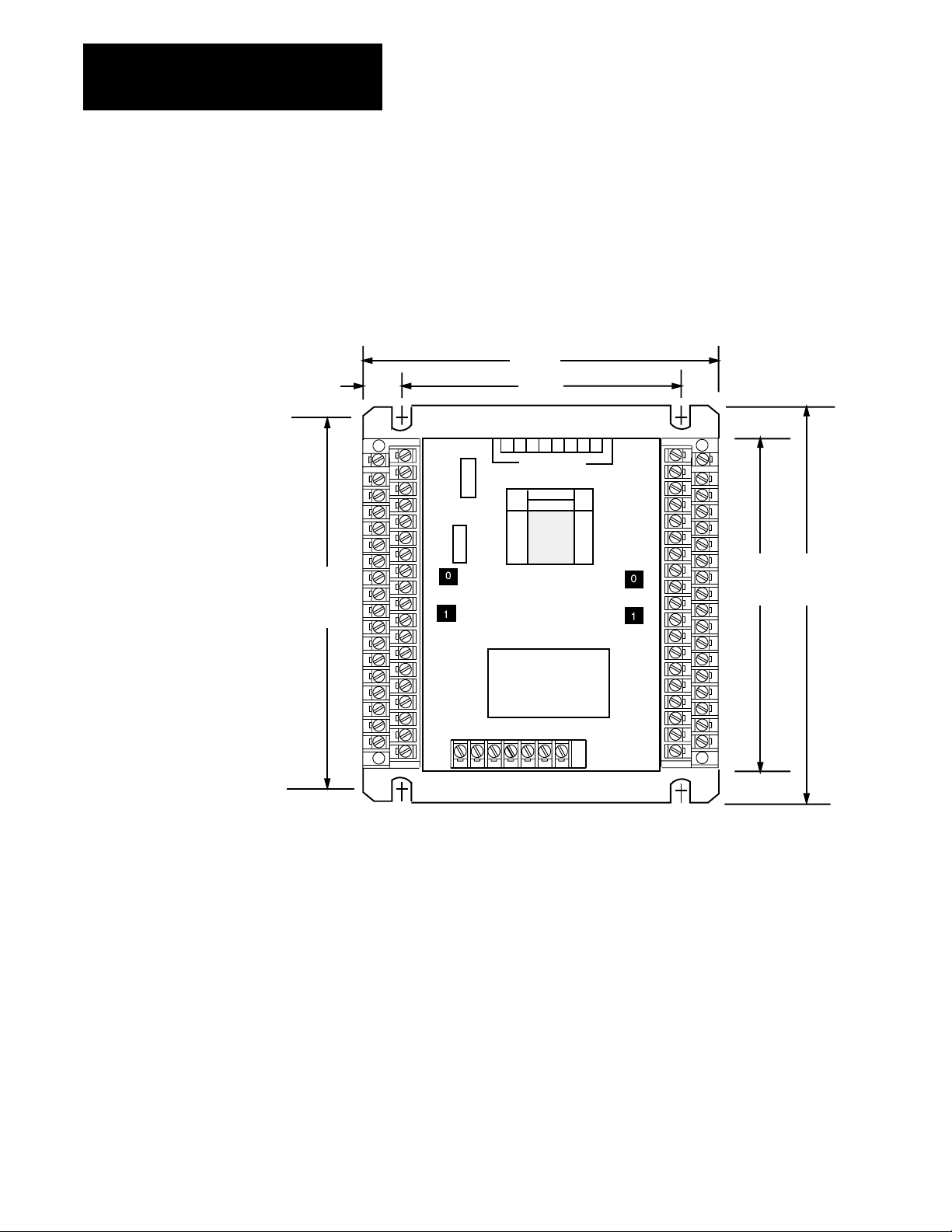
Mounting dimensions for the block I/O module are shown in Figure 2.1.
Mount the blocks horizontally with a minimum of 2” between blocks. This
air gap is necessary to maintain proper cooling air flow through the block.
Figure 2.1
Mounting
IOVW)
Dimensions for the Block I/O Module (Cat. No. 1791IOBW and
6.15
(156.21)
4.8
(122.0)
87654321
CONFIGURATION
SWITCHES
RACK
ADDR
POWER
ACTIVE
COMM
FUSE
1791IOBW
64 POINT
24VDC DISTRIBUTED
I/O MODULE
CONFIGURATION SWITCHES
6.2
(157.0)
7.0
(178.0)
Dimensions:
6.15W x 7.0H x 1.72D
(156.21W x 178.0H x 43.7D)
10916I
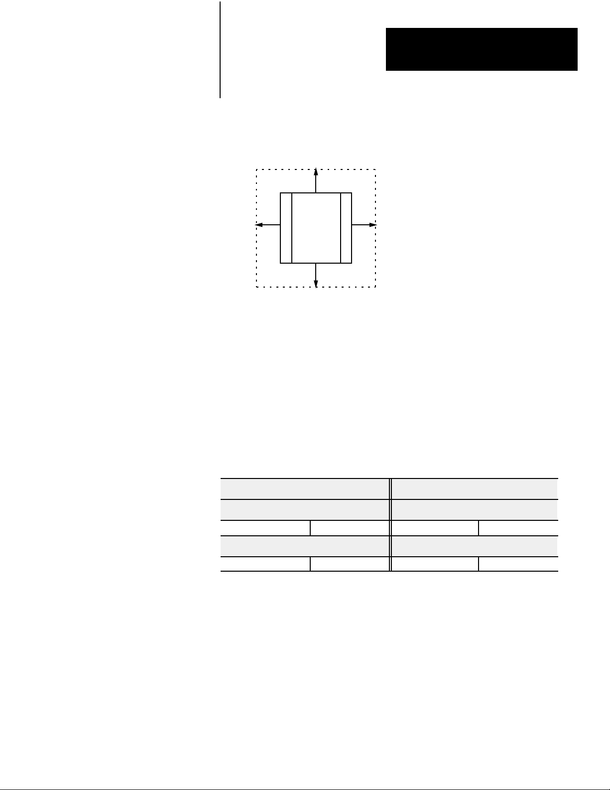
The operating temperature in the air gap between block I/O modules must
not exceed 60
o
C (140oF). The dimensions of the air gap required are
shown in Figure 2.2.
2-2
Page 14
Chapter 2
Installing Block I/O
Connecting Wiring
Figure 2.2
Clearance
2
(50.8)
Required for Block I/O Modules
2
(50.8)
2
(50.8)
Inches
(Millimeters)
2
(50.8)
10919I
Connections to the block I/O module are made to the removable terminal
blocks on each side of the module. Input connections are on the left side,
and output connections are on the right side. The input terminal block is
keyed differently from the output terminal block to prevent incorrect
insertion.
Wiring connections for the 1791-IOBW and -IOVW are shown in Tables
2.A through 2.D.
Catalog Number 1794IOBW Catalog Number 1794IOVW
Input Terminal Wiring Input Terminal Wiring
Groups 0 and 1 (TRM1) Table 2.A, page 24 Groups 0 and 1 (TRM1) Table 2.C, page 26
Output Terminal Wiring Output Terminal Wiring
Groups 0 and 1 (TRM3) Table 2.B, page 25 Groups 0 and 1 (TRM3) Table 2.D, page 27
Remote I/O link wiring connections are shown in Figure 2.3.
2-3
Page 15

Chapter 2
Installing Block I/O
Table 2.A
1791IOBW
Terminal
Number
1 Common A Common A 19 Common B Common B
2 Input 00 Input 00 20 Input 00 Input 00
3 Input 01 Input 01 21 Input 01 Input 01
4 Input 02 Input 02 22 Input 02 Input 02
5 Input 03 Input 03 23 Input 03 Input 03
6 Input 04 Input 04 24 Input 04 Input 04
7 Input 05 Input 05 25 Input 05 Input 05
8 Input 06 Input 06 26 Input 06 Input 06
9 Input 07 Input 07 27 Input 07 Input 07
10 Input 10 Input 08 28 Input 10 Input 08
11 Input 11 Input 09 29 Input 11 Input 09
12 Input 12 Input 10 30 Input 12 Input 10
13 Input 13 Input 11 31 Input 13 Input 11
14 Input 14 Input 12 32 Input 14 Input 12
15 Input 15 Input 13 33 Input 15 Input 13
16 Input 16 Input 14 34 Input 16 Input 14
17 Input 17 Input 15 35 Input 17 Input 15
18 N.C. N.C. 36 N.C. N.C.
Input Assignment
Group 0
PLC SLC
Terminal
Number
37 N.C. N.C.
Input T
Input Assignment
Group 1
PLC SLC
erminal W
iring for Groups 0 and 1 (TRM1)
+V
Common
2
36 37
PLC SLC
1
COM
00
01
02
03
04
06
10
12
14
16
17
NC
COM
00
01
02
04
06
10
12
14
16
17
NC
INPUT
05
07
11
13
15
03
05
07
11
13
15
NC
INPUT
COM
00
01
02
03
04
05
06
0
1
07
0
08
09
10
11
12
13
14
15
NC
COM
00
01
02
03
04
05
06
07
08
09
10
11
12
1
13
14
15
NC
NC
12496I
2-4
Page 16
Chapter 2
Installing Block I/O
Table 2.B
1791IOBW
Terminal
Number
1 N.C. N.C. 20 Common A Common A
2 Common B Common B 21 Output 17 Output 15
3 Output 17 Output 15 22 Output 16 Output 14
4 Output 16 Output 14 23 Output 15 Output 13
5 Output 15 Output 13 24 Output 14 Output 12
6 Output 14 Output 12 25 Output 13 Output 11
7 Output 13 Output 11 26 Output 12 Output 10
8 Output 12 Output 10 27 Output 11 Output 09
9 Output 11 Output 09 28 Output 10 Output 08
10 Output 10 Output 08 29 Output 07 Output 07
11 Output 07 Output 07 30 Output 06 Output 06
12 Output 06 Output 06 31 Output 05 Output 05
13 Output 05 Output 05 32 Output 04 Output 04
14 Output 04 Output 04 33 Output 03 Output 03
15 Output 03 Output 03 34 Output 02 Output 02
16 Output 02 Output 02 35 Output 01 Output 01
17 Output 01 Output 01 36 Output 00 Output 00
18 Output 00 Output 00 37 VDC A VDC A
19 VDC B VDC B
Output Assignment
Group 1
PLC SLC
Terminal
Number
Output T
Output Assignment
Group 0
PLC SLC
erminal W
iring for Groups 0 and 1 (TRM2)
PLCSLC
OUTPUT
+VDC
05
07
09
11
0
13
15
+VDC
01
03
05
07
09
11
13
15
COM
1
NC
01
03
COM
00
L
02
04
06
08
10
12
14
00
L
02
04
06
08
10
12
14
OUTPUT
+VDC
03
05
07
11
13
0
15
17
+VDC
01
03
05
07
11
13
15
17
COM
1
NC
01
COM
L
00
L
02
04
06
10
12
14
16
00
02
04
06
10
12
14
16
1
3637
+VDC
Field
Device
Field
Device
Field
Device
Field
Device
2
Common
12497I
2-5
Page 17
Chapter 2
Installing Block I/O
Table 2.C
1791IOVW
Input Assignment
Terminal
Number
Group 0
Terminal
Number
PLC SLC
1 VDC A VDC A 19 VDC B VDC B
2 Input 00 Input 00 20 Input 00 Input 00
3 Input 01 Input 01 21 Input 01 Input 01
4 Input 02 Input 02 22 Input 02 Input 02
5 Input 03 Input 03 23 Input 03 Input 03
6 Input 04 Input 04 24 Input 04 Input 04
7 Input 05 Input 05 25 Input 05 Input 05
8 Input 06 Input 06 26 Input 06 Input 06
9 Input 07 Input 07 27 Input 07 Input 07
10 Input 10 Input 08 28 Input 10 Input 08
11 Input 11 Input 09 29 Input 11 Input 09
12 Input 12 Input 10 30 Input 12 Input 10
13 Input 13 Input 11 31 Input 13 Input 11
14 Input 14 Input 12 32 Input 14 Input 12
15 Input 15 Input 13 33 Input 15 Input 13
16 Input 16 Input 14 34 Input 16 Input 14
17 Input 17 Input 15 35 Input 17 Input 15
18 N.C. N.C. 36 N.C. N.C.
Input Assignment
Group 1
PLC SLC
37 N.C. N.C.
Input T
erminal W
iring for Groups 0 and 1 (TRM1)
PLC SLC
+VDC
2
36 37
1
+VDC
00
01
02
03
04
05
06
07
10
11
12
13
14
15
16
17
NC
+VDC
00
01
02
03
04
05
06
07
10
11
12
13
14
15
16
17
NC
NC
INPUT
0
1
NC
NC
+VDC
00
02
04
06
08
10
12
14
+VDC
00
02
04
06
08
10
12
14
01
03
05
07
09
11
13
15
01
03
05
07
09
11
13
15
NC
INPUT
0
1
12493I
2-6
Page 18

Chapter 2
Installing Block I/O
Table 2.D
1791IOVW
Terminal
Number
1 N.C. N.C. 20 Common A Common A
2 Common B Common B 21 Output 17 Output 15
3 Output 17 Output 15 22 Output 16 Output 14
4 Output 16 Output 14 23 Output 15 Output 13
5 Output 15 Output 13 24 Output 14 Output 12
6 Output 14 Output 12 25 Output 13 Output 11
7 Output 13 Output 11 26 Output 12 Output 10
8 Output 12 Output 10 27 Output 11 Output 09
9 Output 11 Output 09 28 Output 10 Output 08
10 Output 10 Output 08 29 Output 07 Output 07
11 Output 07 Output 07 30 Output 06 Output 06
12 Output 06 Output 06 31 Output 05 Output 05
13 Output 05 Output 05 32 Output 04 Output 04
14 Output 04 Output 04 33 Output 03 Output 03
15 Output 03 Output 03 34 Output 02 Output 02
16 Output 02 Output 02 35 Output 01 Output 01
17 Output 01 Output 01 36 Output 00 Output 00
18 Output 00 Output 00 37 VDC A VDC A
19 VDC B VDC B
Output Assignment
Group 1
PLC SLC
Terminal
Number
Output T
Output Assignment
Group 0
PLC SLC
erminal W
iring for Groups 0 and 1 (TRM2)
PLCSLC
OUTPUT
+VDC
01
03
05
07
09
11
0
13
15
COM
+VDC
01
03
05
07
09
11
13
15
COM
1
NC
00
L
02
04
06
08
10
12
14
00
L
02
04
06
08
10
12
14
OUTPUT
+VDC
03
05
07
11
13
0
15
17
+VDC
01
03
05
07
11
13
15
17
COM
1
NC
01
COM
00
L
02
04
06
10
12
14
16
00
L
02
04
06
10
12
14
16
1
+VDC
3637
Field
Device
Field
Device
Field
Device
Field
Device
2
Common
12491I
Table 2.E
Block Designations
Wiring
Connector Designation Description
1 (BLU) Blue wire RIO
2 (CLR) Clear wire RIO
Remote I/O Connector
Input Terminals 1 thru 37 See Tables
Output Terminals 1 thru 37 See Tables
Shield Shield RIO
Chassis GND
Chassis Ground
24VDC RET +24V ground
24VDC +24V dc
2-7
Page 19

Chapter 2
Installing Block I/O
Power Supply Requirements
An external 24V dc (+10/-25%) power supply is required to power the
block. Total current required to power the block is equal to 100mA.
In addition, the external power supply should have current limiting
capabilities. The voltage range must not exceed 18.0-26.4V dc.
Wiring Requirements
Wiring cable requirements are shown in Table 2.F.
Table 2.F
W
Acceptable
iring Cables for Block I/O Connection
Use Cable Type With
Remote I/O Link Belden 9463
Input and Output wiring
Up to 14AWG (2mm2)Stranded with
3/64 inch (1.2mm) insulation
Figure 2.3
Remote
I/O Link W
GROUP No.
11
2
(CLR)
Shield
1
(BLU)
iring
Chassis
GND
24VDC
RET
24VDC
PLC2, PLC3, PLC5 family programmable
controllers and SLC controllers
All
GROUP No.
TERMINATION
RESISTOR
150 OHM
OFF
82 OHM
2-8
Connnection
1
(BLU)2 (CLR)
Clear Wire X
Blue Wire X
Shield Wire X
10928I
Shield
Page 20

Chapter 2
Installing Block I/O
Remote
I/O Link W
iring
Blocks must be wired in series as shown in Figure 2.4. Do not attempt to
wire any block in parallel.
The number of blocks used depends not only on the user requirements but
also on the system used.
Figure 2.4
Connection for Block I/O Using PLC2, PLC3 or PLC5 Family
Series
Programmable Controllers
To Programmable Controller,
remote I/O adapter or
Scanner Module
1 I/O Rack
Install terminating resistor on last block.
1 I/O Rack
10929I
2-9
Page 21

Chapter 2
Installing Block I/O
Termination Resistor
A termination resistor must be used on the last block in the series. A 150
ohm and 82 ohm termination resistors are built into the unit. To select the
termination resistor, position the switch to the desired position as shown in
Figure 2.5.
Extended Node Capability
Figure 2.5
the T
Installing
ermination Resistor
2
(CLR)
Shield
1
(BLU)
24VDC
Chassis
GND
Position switch to connect termination resistor
across 1 and 2 as follows:
150 ohm position switch at top;
82 ohm resistor position switch at bottom;
OFF no resistor position switch in middle.
RET
24VDC
TERMINATION
RESISTOR
150 OHM
OFF
82 OHM
10930I
If this is the last block on the remote I/O link in a PLC system, you must
use a terminating resistor to terminate both ends of the remote I/O link
(scanner end and last block end). The size of the terminator is determined
by the system configuration.
Older configurations can use a 150 ohm resistor at both ends. With newer
devices that can support it, you can use an 82 ohm termination resistor at
both ends. The 82 ohm terminators provide “extended node” capability
which allows you to have up to 32 physical devices on the RIO link. (The
number of logical racks capable of being addressed by the scanner is not
affected.)
2-10
ATTENTION: Devices that are operating at 230.4K baud must
have 82 ohm terminators in place for proper operation.
Page 22

Chapter 2
Installing Block I/O
Compatibility
of 1771 I/O
Products with Extended
Node Operation
Certain products are not compatible with extended node capabilities
obtained with the use of 82 ohm terminators. The following table lists
those products that are not compatible.
Device Series
Scanners 1771SN All
1772SD All
1772SD2 All
1
1775SR
1775S4A
1775S4B
Adapters 1771AS All
1771ASB Series A
1771DCM All
Miscellaneous 1771AF All
1771AF1 All
1
When
using PLC3 programmable controllers, you must use a
1775S5 or SR5 scanner module.
or S4B scanner modules.
1
1
Do not use
All
All
All
1775SR, S4A
2-11
Page 23

Chapter
Configuring Your Block I/O
3
Chapter
Objectives
Setting the Configuration Switches
In this chapter you will learn how to configure your block I/O when used
with PLC family programmable controllers. This includes the following:
setting the configuration switches
addressing the block I/O
To configure your block I/O for SLC family processors, refer to the user
manual for the 1747-SN scanner module.
ATTENTION: This module is not compatible with the
1747-DSN distributed I/O scanner module.
Each block I/O module has switches for setting:
transmission (baud) rate - used to set the communication rate chosen
for the remote I/O link
last state - when last state is enabled, a processor reset will keep the
outputs in their present (last) state; when last state is disabled, the
outputs will reset
processor restart lockout (PRL) - when PRL is enabled, the
programmable controller cannot automatically start up the module’s
communications if the power has been cycled to either the module or
the programmable controller
last rack - used to identify if the module contains the highest numbered
I/O group for the associated rack number
I/O group adress - used to identify which module group (0-1, 2-3, 4-5
or 6-7) the module should assign to its inputs/outputs
rack address - used to select the rack address of the module
RIO termination resistor - used to connect an internal resistor
(82 ohm, 150 ohm, or no resistor) across LINE 1 and 2 on the remote
I/O terminals
These switches are all accessible on the front or top of the module, as
shown in Figure 3.1.
3-1
Page 24

Chapter 3
Configuring Your Block I/O
Configuration
Switches
Figure 3.1
Setting Locations (1791IOBW shown)
Switch
Rack Address
Switches
COM
00
02
04
06
10
12
14
16
NC
COM
00
02
04
06
10
12
14
16
NC
NC
87654321
01
03
05
07
11
13
15
17
01
03
05
07
11
13
15
17
2
(CLR)
RACK
ADDR
Shield
POWER
ACTIVE
COMM
FUSE
(BLU)
1
Chassis
GND
CONFIGURATION
SWITCHES
INPUT
1791IOBW
64
POINT
24V DC DISTRIBUTED
I/O MODULE
CONFIGURATION
BAUD
1 2
RATE
BPS
PRL
NO OFF
YES ON
4
24VDC
RET
OFF OFF
ON OFF
OFF ON
ON ON
LAST
RACK
NO OFF
YES ON
24VDC
57.6K
115.2KBPS
230.4KBPS
UNUSED
5
OUTPUT
SWITCHES
LAST
3
STATE
LATCH
OFF
RESET
ON
NOT
8
USED
I/O
GROUP
0 to 1
2 to 3
4 to 5
6 to 7
T
ermination Resistor
6
OFF OFF
OFF ON
ON OFF
ON ON
150 Ohm
Off
82 Ohm
7
+VDC
L
01
03
05
07
11
13
15
17
COM
+VDC
01
03
05
07
11
13
15
17
COM
00
02
04
06
10
12
14
16
00
L
02
04
06
10
12
14
16
NC
3-2
Termination
Resistor Switch
10931I
Page 25

Chapter 3
Configuring Your Block I/O
Rack Address Switch
ON
134256
Set to OFF
I/O Group
0 TO 1
2 TO 3
4 TO 5
6 TO 7
Last
Rack
NO OFF
YES ON
Last Rack Switch 5
PLC2
OFF When module does not contain the
highest numbered I/O group for the associated
rack number.
ON When module does contain the highest
numbered I/O group for the associated rack
number.
PLC3
This switch must always be set to OFF."
PLC5
This switch not used.
Figure 3.2
Configuration
8
6
7
OFF OFF
OFF ON
ON OFF
ON ON
5
Switch Settings
COM
00
01
02
03
04
05
RACK
06
07
ADDR
10
11
12
13
14
15
Configuration
8
7
87654321
CONFIGURATION
SWITCHES
INPUT
Switch
(Top View of Switch)
654321
OUTPUT
ON
+VDC
05
07
13
15
00
L
01
02
03
04
06
10
11
12
14
Last State Switch 3
CAUTION: Set switch 3 to the ON
position to deenergize outputs wired to
this module when a fault is detected. If
switch 3 is set to the OFF position,
outputs connected to this module
remain in their last state when a fault
occurs and machine motion may
continue after fault detection.
4
PRL
Disabled OFF
Enabled ON
Processor Restart Lockout (PRL) Switch 4
When PRL is enabled (on), the programmable
controller cannot automatically start up the module'
communications if the power has been cycled to
either the module or the programmable controller
BAUD RAT E
57.6kbps
115.2kbps
230.4kbps
Unused
AST
L
STATE
Latch
Reset
OFF
ON
s
3
OFF
ON
OFF
ON
1 2
OFF
OFF
ON
ON
10932I
3-3
Page 26

Chapter 3
Configuring Your Block I/O
Table 3.A
Rack Number for PLC2 Family Processors
I/O
1747SN
Rack
Number
Rack 0 Rack 1 Rack 1 Not Valid Rack 0 Rack 0 0 0 0 0 0 0
Rack 1 Rack 2 Rack 2 Rack 1 Rack 1 Rack 1 0 0 0 0 0 1
Rack 2 Rack 3 Rack 3 Rack 2 Rack 2 Rack 2 0 0 0 0 1 0
Rack 3 Rack 4 Rack 4 Rack 3 Rack 3 Rack 3 0 0 0 0 1 1
1771SN
Rack
Number
Rack 5 Rack 5 Rack 4 Rack 4 Rack 4 0 0 0 1 0 0
Rack 6 Rack 6 Rack 5 Rack 5 Rack 5 0 0 0 1 0 1
Rack 7 Rack 7 Rack 6 Rack 6 Rack 6 0 0 0 1 1 0
PLC2
Rack
Number
PLC5
Rack
Number
Rack 7 Rack 7 Rack 7 0 0 0 1 1 1
Rack 10 Rack 10 Rack 10 0 0 1 0 0 0
Rack 11 Rack 11 Rack 11 0 0 1 0 0 1
Rack 12 Rack 12 Rack 12 0 0 1 0 1 0
Rack 13 Rack 13 Rack 13 0 0 1 0 1 1
Rack 14 Rack 14 Rack 14 0 0 1 1 0 0
Rack 15 Rack 15 Rack 15 0 0 1 1 0 1
Rack 16 Rack 16 Rack 16 0 0 1 1 1 0
Rack 17 Rack 17 Rack 17 0 0 1 1 1 1
Rack 20 Rack 20 Rack 20 0 1 0 0 0 0
Rack 21 Rack 21 Rack 21 0 1 0 0 0 1
Rack 22 Rack 22 Rack 22 0 1 0 0 1 0
Rack 23 Rack 23 Rack 23 0 1 0 0 1 1
Rack 24 Rack 24 Rack 24 0 1 0 1 0 0
Rack 25 Rack 25 Rack 25 0 1 0 1 0 1
Rack 26 Rack 26 Rack 26 0 1 0 1 1 0
Rack 27 Rack 27 Rack 27 0 1 0 1 1 1
PLC5/250
Rack
Number
Rack 30 Rack 30 0 1 1 0 0 0
Rack 31 Rack 31 0 1 1 0 0 1
Rack 32 Rack 32 0 1 1 0 1 0
Rack 33 Rack 33 0 1 1 0 1 1
Rack 34 Rack 34 0 1 1 1 0 0
Rack 35 Rack 35 0 1 1 1 0 1
Rack 36 Rack 36 0 1 1 1 1 0
Rack 37 Rack 37 0 1 1 1 1 1
PLC3
Rack
Number
Rack 40 1 0 0 0 0 0
Rack 41 1 0 0 0 0 1
Rack 42 1 0 0 0 1 0
Rack 43 1 0 0 0 1 1
Rack Address Switch Position
6 5 4 3 2 1
3-4
Page 27

Chapter 3
Configuring Your Block I/O
1747SN
1747SN
Rack
Rack
Number
Number
Rack
address 77 is an illegal configuration.
PLC5/1
PLC5/15 and PLC5/20 processors can scan racks 0103.
PLC5/25 and PLC5/30 processors can scan racks 0107.
PLC5/40 and PLC5/40L processors can scan racks 0117.
PLC5/60 and PLC5/60L processors can scan racks 0127.
1771SN
1771SN
Rack
Rack
Number
Number
1 processors can scan rack 03.
PLC2
PLC2
Rack
Rack
Number
Number
PLC5
PLC5
Rack
Rack
Number
Number
PLC5/250
PLC5/250
Rack
Rack
Number
Number
PLC3
PLC3
Rack
Rack
Number
Number
Rack Address Switch Position
Rack 44 1 0 0 1 0 0
Rack 45 1 0 0 1 0 1
Rack 46 1 0 0 1 1 0
Rack 47 1 0 0 1 1 1
Rack 50 1 0 1 0 0 0
Rack 51 1 0 1 0 0 1
Rack 52 1 0 1 0 1 0
Rack 53 1 0 1 0 1 1
Rack 54 1 0 1 1 0 0
Rack 55 1 0 1 1 0 1
Rack 56 1 0 1 1 1 0
Rack 57 1 0 1 1 1 1
Rack 60 1 1 0 0 0 0
Rack 61 1 1 0 0 0 1
Rack 62 1 1 0 0 1 0
Rack 63 1 1 0 0 1 1
Rack 64 1 1 0 1 0 0
Rack 65 1 1 0 1 0 1
Rack 66 1 1 0 1 1 0
Rack 67 1 1 0 1 1 1
Rack 70 1 1 1 0 0 0
Rack 71 1 1 1 0 0 1
Rack 72 1 1 1 0 1 0
Rack 73 1 1 1 0 1 1
Rack 74 1 1 1 1 0 0
Rack 75 1 1 1 1 0 1
Rack 76 1 1 1 1 1 0
Not Valid 1 1 1 1 1 1
123456
Each block uses 2 words of output image table memory and 2 words of
input image table memory. Each block occupies 1/4 rack of data table, with
4 blocks comprising 1 logical rack. Image table usage for one assigned
rack number is shown in Figure 3.3. An example of image table usage is
shown in Figure 3.4.
3-5
Page 28

Chapter 3
Configuring Your Block I/O
Figure 3.3
Image T
I/O
1
2
able for One Assigned Rack Number
Block 1 Inputs
Block 2 Inputs
Block 3 Inputs
Block 4 Inputs
0
1
2
3
4
5
6
7
Input Image
710
017
Block 1 Outputs
4 1791IOBW or 1791IOVW per rack
1st 1/4 rack = module group 01
2nd 1/4 rack = module group 23
3rd 1/4 rack = module group 45
4th 1/4 rack = module group 67
PLC2 Example
11100
Type of I/O
1 = Input
0 = Output
I/O Rack Number
Starting
I/O Group
0
110
111
010
011
17 16 15 14 13 12
17 16 15 14 13 12
17 16 15 14 13 12
17 16 15 14 13 12
Rack 1
1791IOVW1791IOBW
Block 2 Outputs
Figure 3.4
Input
T
able Usage Example for One Starting I/O Group with 1791IOBW
and IOVW
PLC3, PLC5, PLC5/250 Example
I/O Bit
I/O Group Number
1791IOVW1791IOBW
Output Image
710
0
1
2
3
4
Block 3 Outputs
Block 4 Outputs
5
6
7
I 1100
Type of I/O
I = Input
O = Output
I/O Rack Number
111076543210
11107654321
111076543210
11107654321
0
0
017
10933I
I/O Bit
I/O Group Number
Input Image
Output Image
3-6
Starting
I/O Group
4
114
115
014
015
17 16 15 14 13 12
17 16 15 14 13 12
17 16 15 14 13 12
11107654321017 16 15 14 13 12
11107654321
111076543210
11107654321
0
0
Input Image
Output Image
10934I
Page 29
Chapter 3
Configuring Your Block I/O
Table 3.B
Input T
erminal Addressing for Groups 0 and 1 (TRM1)
Input
Group 1
Terminal
Number
Input
Assignment
Group 0
Program
Address
1791IOBW
Terminal
Number
Assignment
1 Common A 19 Common B
2 Input 00 1XY00 20 Input 00 1X(Y+1)00
3 Input 01 1XY01 21 Input 01 1X(Y+1)01
4 Input 02 1XY02 22 Input 02 1X(Y+1)02
5 Input 03 1XY03 23 Input 03 1X(Y+1)03
6 Input 04 1XY04 24 Input 04 1X(Y+1)04
7 Input 05 1XY05 25 Input 05 1X(Y+1)05
8 Input 06 1XY06 26 Input 06 1X(Y+1)06
9 Input 07 1XY07 27 Input 07 1X(Y+1)07
10 Input 10 1XY10 28 Input 10 1X(Y+1)10
11 Input 11 1XY11 29 Input 11 1X(Y+1)11
12 Input 12 1XY12 30 Input 12 1X(Y+1)12
13 Input 13 1XY13 31 Input 13 1X(Y+1)13
14 Input 14 1XY14 32 Input 14 1X(Y+1)14
15 Input 15 1XY15 33 Input 15 1X(Y+1)15
16 Input 16 1XY16 34 Input 16 1X(Y+1)16
17 Input 17 1XY17 35 Input 17 1X(Y+1)17
18 N.C. 36 N.C.
37 N.C.
Where: X = Rack Number (1, 2, 3 ...)
Y = Module Group (0, 2, 4, 6)
NOTE:
I XY00
I/O Group
Number
Type
of I/O
1 = Input
0 = Output
I/O Rack
Number
PLC2 Example
1 XY00
I/O Group
Number
I/O Bit
Type
of I/O
I = Input
O = Output
I/O Rack
Number
PLC3, PLC5, PLC5/250 Example
Program
Address
I/O Bit
2
36 37
1
INPUT
COM
00
01
02
03
04
05
06
07
10
11
12
13
14
15
16
NC
COM
00
02
04
06
10
12
14
16
NC
0
17
01
03
05
07
11
13
15
1
17
NC
10935I
3-7
Page 30

Chapter 3
Configuring Your Block I/O
Table 3.C
1791IOBW
Terminal
Number
1 N.C. 20 Ground A
2 Ground B 21 Output 17 0XY17
3 Output 17 0X(Y+1)17 22 Output 16 0XY16
4 Output 16 0X(Y+1)16 23 Output 15 0XY15
5 Output 15 0X(Y+1)15 24 Output 14 0XY14
6 Output 14 0X(Y+1)14 25 Output 13 0XY13
7 Output 13 0X(Y+1)13 26 Output 12 0XY12
8 Output 12 0X(Y+1)12 27 Output 11 0XY11
9 Output 11 0X(Y+1)11 28 Output 10 0XY10
10 Output 10 0X(Y+1)10 29 Output 07 0XY07
11 Output 07 0X(Y+1)07 30 Output 06 0XY06
12 Output 06 0X(Y+1)06 31 Output 05 0XY05
13 Output 05 0X(Y+1)05 32 Output 04 0XY04
14 Output 04 0X(Y+1)04 33 Output 03 0XY03
15 Output 03 0X(Y+1)03 34 Output 02 0XY02
16 Output 02 0X(Y+1)02 35 Output 01 0XY01
17 Output 01 0X(Y+1)01 36 Output 00 0XY00
18 Output 00 0X(Y+1)00 37 VDC A
19 VDC B
Where: X = Rack Number (1, 2, 3 ...)
Output
Assignment
Group 1
Program
Address
Y = Module Group (0, 2, 4, 6)
Terminal
Number
Output T
Output
Assignment
Group 0
NOTE:
O XY00
Type
of I/O
1 = Input
0 = Output
I/O Rack
Number
PLC2 Example
0 XY00
I/O Group
Number
I/O Bit
Type
of I/O
I = Input
O = Output
I/O Rack
Number
PLC3, PLC5, PLC5/250 Example
erminal Addressing for Groups 0 and 1 (TRM2)
Program
Address
I/O Bit
I/O Group
Number
OUTPUT
0
+VDC
1
+VDC
L
01
03
05
07
11
13
15
17
COM
L
01
03
05
07
11
13
15
17
COM
NC
00
02
04
06
10
12
14
16
00
02
04
06
10
12
14
16
36
37
12
10937I
3-8
Page 31

Chapter 3
Configuring Your Block I/O
Table 3.D
Input T
erminal Addressing for Groups 0 and 1 (TRM1)
Input
Group 1
Terminal
Number
Input
Assignment
Group 0
Program
Address
1791IOVW
Terminal
Number
Assignment
1 VDC A 19 VDC B
2 Input 00 1XY00 20 Input 00 1X(Y+1)00
3 Input 01 1XY01 21 Input 01 1X(Y+1)01
4 Input 02 1XY02 22 Input 02 1X(Y+1)02
5 Input 03 1XY03 23 Input 03 1X(Y+1)03
6 Input 04 1XY04 24 Input 04 1X(Y+1)04
7 Input 05 1XY05 25 Input 05 1X(Y+1)05
8 Input 06 1XY06 26 Input 06 1X(Y+1)06
9 Input 07 1XY07 27 Input 07 1X(Y+1)07
10 Input 10 1XY10 28 Input 10 1X(Y+1)10
11 Input 11 1XY11 29 Input 11 1X(Y+1)11
12 Input 12 1XY12 30 Input 12 1X(Y+1)12
13 Input 13 1XY13 31 Input 13 1X(Y+1)13
14 Input 14 1XY14 32 Input 14 1X(Y+1)14
15 Input 15 1XY15 33 Input 15 1X(Y+1)15
16 Input 16 1XY16 34 Input 16 1X(Y+1)16
17 Input 17 1XY17 35 Input 17 1X(Y+1)17
18 N.C. 36 N.C.
37 N.C.
Where: X = Rack Number (1, 2, 3 ...)
Y = Module Group (0, 2, 4, 6)
NOTE:
I XY00
I/O Group
Number
Type
of I/O
1 = Input
0 = Output
I/O Rack
Number
1 XY00
I/O Group
Number
I/O Bit
Type
of I/O
I = Input
O = Output
I/O Rack
Number
Program
Address
I/O Bit
2
1
INPUT
COM
00
01
02
03
04
05
06
07
10
11
12
13
14
15
16
NC
COM
00
02
04
06
10
12
14
16
NC
36
37
0
17
01
03
05
07
11
13
15
1
17
NC
10939I
PLC2 Example
PLC3, PLC5, PLC5/250 Example
3-9
Page 32

Chapter 3
Configuring Your Block I/O
Table 3.E
1791IOVW
Terminal
Number
1 N.C. 20 Ground A
2 Ground B 21 Output 17 0XY17
3 Output 17 0X(Y+1)17 22 Output 16 0XY16
4 Output 16 0X(Y+1)16 23 Output 15 0XY15
5 Output 15 0X(Y+1)15 24 Output 14 0XY14
6 Output 14 0X(Y+1)14 25 Output 13 0XY13
7 Output 13 0X(Y+1)13 26 Output 12 0XY12
8 Output 12 0X(Y+1)12 27 Output 11 0XY11
9 Output 11 0X(Y+1)11 28 Output 10 0XY10
10 Output 10 0X(Y+1)10 29 Output 07 0XY07
11 Output 07 0X(Y+1)07 30 Output 06 0XY06
12 Output 06 0X(Y+1)06 31 Output 05 0XY05
13 Output 05 0X(Y+1)05 32 Output 04 0XY04
14 Output 04 0X(Y+1)04 33 Output 03 0XY03
15 Output 03 0X(Y+1)03 34 Output 02 0XY02
16 Output 02 0X(Y+1)02 35 Output 01 0XY01
17 Output 01 0X(Y+1)01 36 Output 00 0XY00
18 Output 00 0X(Y+1)00 37 VDC A
19 VDC B
Where: X = Rack Number (1, 2, 3 ...)
Output
Assignment
Group 1
Program
Address
Y = Module Group (0, 2, 4, 6)
Terminal
Number
Output T
Output
Assignment
Group 0
NOTE:
O XY00
Type
of I/O
1 = Input
0 = Output
I/O Rack
Number
PLC2 Example
0 XY00
I/O Group
Number
I/O Bit
Type
of I/O
I = Input
O = Output
I/O Rack
Number
PLC3, PLC5, PLC5/250 Example
erminal Addressing for Groups 0 and 1 (TRM2)
Program
Address
I/O Bit
I/O Group
Number
OUTPUT
0
+VDC
1
+VDC
01
03
05
07
11
13
15
17
COM
01
03
05
07
11
13
15
17
COM
NC
00
L
02
04
06
10
12
14
16
00
L
02
04
06
10
12
14
16
36
37
2
1
10941I
3-10
Page 33

Troubleshooting
Chapter
4
Chapter
Objectives
Indicators
In this chapter you will learn about the indicators on the block I/O module,
and how to use them to troubleshoot the unit.
Each block I/O module has LED indicators (Figure 4.1) which provide
indication of specific functions. Each module has the following:
Status Indicators - Indicators are provided for power, active,
communication and fuse blown indications. An LED array provides
input/output status.
POWER indicator -
-green -on continuously if customer voltage is present;
off if power is not applied or there is an internal power supply
problem.
ACTIVE indicator -
-red if the CPU is not running;
green if the CPU is operating correctly.
COMM indicator - indicates the status of the remote I/O link.
-green when communication is correctly established;
off when communication is not established;
flashing when programmable controller is in PROG mode.
FUSE indicator - indicates the status of the 2 output fuses.
-off if both fuses are intact;
red if either fuse opens.
The I/O status array is an 8 by 8 array of 64 LEDs capable of displaying
the status of 32 inputs and 32 outputs at any one time.
Refer to Table 4.A below for status indications reported by the LED
indicators.
4-1
Page 34

Chapter 4
Troubleshooting
POWER
ACTIVE
COMM
FUSE
Figure 4.1
Indicators
shown)
on the 1791IOBW and IOVW Block I/O Modules (PLC labels
COM
00
01
02
03
04
06
10
12
14
16
NC
COM
00
01
02
03
04
06
10
12
05
RACK
07
ADDR
11
13
15
17
05
07
11
87654 3 21
CONFIGURATIO
N
SWITCHES
POWER
ACTIVE
COMM
FUSE
+VDC
03
05
07
11
13
15
17
COM
+VDC
03
05
07
11
00
01
02
04
06
10
12
14
16
00
01
02
04
06
10
4-2
INPUT
00
01
02
03
04
05
06
07
OI O I
10
11
12
13
14
15
16
17
OUTPUT
10
00
11
01
12
02
13
03
14
04
15
05
16
06
17
07
10943I
Page 35
Chapter 4
(green)
ACTIVE
FUSE
Troubleshooting
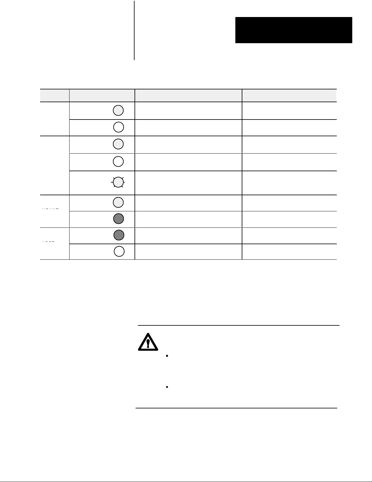
Table 4.A
roubleshooting Chart
T
Indication Probable Cause Corrective Action
POWER
(green)
COMM
(green)
ACTIVE
(green/red)
FUSE
(red)
Green
I/O status on/off
Off
Solid green
Off
Flashing green
Green
Red
Red
Off
Normal indication None required
No 24V dc power connected, or hardware fault. Check 24V dc power to block
Normal indication module is communicating with
the programmable controller
No communication with adapter, scanner etc.
Reset command (or output disable bit for SLC) has
been issued by processor, scanner or adapter.
SLC or programmable controller not in run mode.
Normal indication None
Internal CPU fault Return module for repair
One or more fuses are open Replace blown fuse
Normal indication None required
None required
Check that power LED is on. Make sure that
proper number of blocks are configured.
Check program. Correct as necessary.
Place in run mode.
Replacing
a Fuse
The block I/O module has one fuse for each group of outputs. To replace a
fuse, proceed as follows.
1. Remove power to the block I/O module.
ATTENTION: Remove power to the block I/O module before
attempting to replace the fuse.
Failure to remove power from the block I/O module could
cause injury or equipement damage due to possible
unexpected operation.
Failure to remove power from the module could cause
module damage, degradation of performance or injury.
2. Remove the four screws securing the cover to the block I/O module.
3. Locate and remove the blown fuse.
4-3
Page 36

Chapter 4
Troubleshooting
4. Replace the blown fuse with a 5.0A slow blow fuse.
5. Reinstall cover and secure with four screws removed in step 2.
6. Reapply power to the module.
Summary
In this chapter you learned what the LED indicators represent, and how to
interpret them
4-4
Page 37

Specifications
General Specifications
Appendix
A
External power
Power Dissipation 15.1 Watts (maximum); 7.6 Watts (typical)
Thermal Dissipation 51.8 BTU/hr (maximum); 25.9 BTU/hr (typical)
Remote I/O Isolation 850V dc (transformer) for 1 second
Interconnect cable length
(PLC or SLC)
Cable requirements RIO - Belden 9463
Dimensions
Conductors Wire Size
Category
Environmental Conditions
Operating Temperature
Storage Temperature
Relative Humidity
Operating
Nonoperating
1
Refer
to publication 1770-4.1, Programmable Controller Wiring and Grounding Guidelines
Range: 18 to 26.4V dc
100mA @ 24V dc; initial surge 2.0A for 10ms
RIO: 57.6K 10,000 cable-feet
115.2K 5,000 cable-feet
230.4K 2,500 cable-feet
Inches: 6.15W x 7.0H x 1.75D
Millimeters: 156.21W x 178.0H x 44.7D
14 gauge (2mm2) stranded (maximum)
3/64 inch (1.2mm) insulation (maximum)
1
2
32 to 140oF (0 to 60oC)
-40 to 185oF (-40 to 85oC)
5 to 95% noncondensing
5 to 80% noncondensing
Input Specifications
Number of Inputs 32 (2 groups of 16)
Input type 1791-IOBW - Sinking; 1791-IOVW - Sourcing
On-state voltage range 12.0 to 26.4V dc
Minimum on-state input current 1.56mA
Maximum off-state voltage 7.0V dc
Maximum off-state current 1.0mA dc
Onstate Current (typical) 5.2mA @ 24V dc
Input Impedance (nominal) 4.6K
Maximum turn on time 10msec (+4ms)
Maximum turn off time 10msec (+4ms)
Input to system isolation 1500V ac (opto) for 1 second
Group to group isolation 1500V ac (air gap) for 1 second
A-1
Page 38

Appendix A
Specifications
Output Specifications
Number of outputs 32 (2 groups of 16)
Output type 1791-IOBW - Source; 1791-IOVW - Sink
Maximum output voltage range 18.0 to 26.4V dc @ 300mA resistive
Maximum on-state voltage drop 1.5V dc @ 25oC at rated current
Maximum on-state current 300mA per point
Minimum on-state current 5mA
Maximum output current per
output group
Maximum surge current 1.0A for 25ms, 1 pulse per second max.
Maximum off-state voltage 26.4V dc
Maximum off-state leakage
current
Maximum turn on time 2.0ms
Maximum turn off time 2.0ms
Fuse type 5.0A slow blow (5 X 20mm size) - one per group
Output to system isolation 1500V ac (opto) for 1 second
Group to group isolation 1500V ac (air gap) for 1 second
2.4A continuous
0.5mA
A-2
Page 39

Index
Symbols
**Empty**, 13
B
baud rate, 31, 33
C
compatibility, 11
extended node numbers, 211
configuration switches, 33
setting, 31
connection, in a PLC system, 16
connections, wiring, 23
D
description, P2, 11
IOBX, 13
IOVW, 14
dimensions, mounting, 22
IOVX groups 0 and 1, 39
inputs, sinking, 13
installation, termination resistor, 210
L
last rack, 31, 33
LED indicators, 41
M
mounting, clearance, 23
O
output, sinking, 15
output terminal addressing
IOBX groups 0 and 1, 38
IOVX groups 0 and 1, 310
outputs, sourcing, 14
P
E
extended node capability, 210
F
fuses, removing and replacing, 43
G
group address, 31, 33
I
image table usage, 35
indicators
I/O status array, 13
locations, 42
status, 13
status reported, 41
input, sourcing, 14
input terminal addressing
IOBX groups 0 and 1, 37
power requirements, 28
processor restart lockout, 31, 42
R
rack address, 31
related publications, P2
S
sinking inputs, 13
description, 13
sourcing outputs, 13
description, 14
specifications, A1
switch
configuration, 12
rack address, 12
termination resistor, 12
switch assemblies, 12
switch selections, I/O rack number, PLC-2,
34
Page 40

I–2
Index
switch settings, 33
T
termination resistor
installation, 210
internal, 31
troubleshooting chart, 43
W
wiring
block designations, 27
cable requirements, 28
IOBX input terminals, 0 and 1, 24
IOBX output terminals, 0 and 1, 25
IOVX input terminals, 0 and 1, 26
IOVX output terminals, 0 and 1, 27
remote I/O link, 28
wiring connections, 23
wiring terminals, 12
Page 41

Worldwide representation.
AllenBradley, a Rockwell Automation Business, has been helping its customers improve
productivity and quality for more than 90 years. We design, manufacture and support a broad
range of automation products worldwide. They include logic processors, power and motion
control devices, operator interfaces, sensors and a variety of software. Rockwell is one of the
worlds leading technology companies.
Argentina •
Denmark • Ecuador
Ireland
Philippines •
Sweden
Australia • Austria • Bahrain
• Egypt • El Salvador • Finland • France •
• Israel • Italy • Jamaica •
• Belgium • Brazil •
Bulgaria • Canada
Germany • Greece • Guatemala • Honduras • Hong Kong • Hungary
Japan • Jordan • Korea • Kuwait • Lebanon
• Chile •
China, PRC • Colombia
• Malaysia • Mexico •
Poland • Portugal • Puerto Rico • Qatar • Romania • Russia-CIS • Saudi Arabia • Singapore
• Switzerland • T
aiwan
• Thailand • T
urkey • United Arab Emirates • United Kingdom • United States • Uruguay
• Costa Rica •
Netherlands
• New Zealand •
• Slovakia • Slovenia •
Croatia • Cyprus
Norway
South Africa, Republic
• V
enezuela
• Iceland •
• Yugoslavia
AllenBradley Headquarters, 1201 South Second Street, Milwaukee, WI 53204 USA, Tel: (1) 414 3822000 Fax: (1) 414 3824444
Publication 1791-6.5.7 - January 1995
Supersedes
publication 17916.5.7 - May 1993
Copyright
• Czech Republic •
India • Indonesia
• Pakistan •
Peru
•
• Spain •
P/N
1995 Allen-Bradley Co. Inc. Printed in USA
955121-07
•
 Loading...