

Page 1
Using Halfwave Rectifying Load Devices (Single
Diode) with 1791 ac Output Modules
Application Information
Some ac output modules use zero-crossing technology to allow output turn-on
when the voltage is less than some specified level (typically 40–50V). This type
of circuit greatly reduces the stress on contacts and other devices that are
sensitive to current surges.
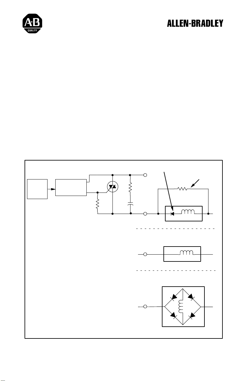
When using an output module that includes zero-crossing technology with a
device that includes a single diode in series with the load, place a shunt resistor
across the load. The resistor is required to allow proper output turn-on.
Single rectifying diode
Simplified Circuit Diagram
Control
1. When L2 is positive with respect to L1,
capacitor C1 is charged.
When the polarity switches, the diode
2.
prevents C1 from discharging.
3. With C1 charged (possibly up to line voltage),
the zerocrossing optotriac sees that voltage,
and won't turn on.
4. The shunt resistor allows a bleedof
voltage on the capacitor
function properly.
ZeroCrossing
Optoisolation
, allowing the circuit to
f of the
C1
in series with load.
L1
Shunt Resistor required
39KΩ
Load
No rectifying diode.
Shunt Resistor NOT required
Load
Full wave rectifier
.
Shunt Resistor NOT required
L2
L2
Load
L2
Page 2

Application Information
Using Halfwave Rectifying Load Devices
(Single Diode) with 1791 ac Output Modules
1791 modules currently using zero-crossing technology include:
1791-0A16 series B
1791-0A32 series B
1791-8AC series B
1791-16AC series B
1791-24A8 series B
WORLD HEADQUARTERS
Allen-Bradley
1201 South Second Street
Milwaukee, WI 53204 USA
Tel: (414) 382-2000
Telex: 43 11 016
FAX: (414) 382-4444
With offices in major cities worldwide
Publication 1791-5.3 – July 1994 PN 955118–66
Copyright 1994 Allen-Bradley Company, Inc. Printed in USA
 Loading...