

Page 1
Installation Instructions
DeviceNet Base RTD and Thermocouple
CompactBlock LDX I/O
(Cat. Nos. 1790D-4R0, -4T0, -T4R0, -T4T0)
What This Document Describes
This document describes how to install your CompactBlock
LDX™ I/O blocks.
For information on: Refer to page:
EDS File Requirements below
Important User Information 2
Installing CompactBlock I/O 5
Wiring the Terminal Blocks 8
Connecting the Field Wiring 9
Connecting the DeviceNet Cable 14
I/O Memory Mapping 15
Troubleshooting with the Indicators 17
Module Specifications 18
EDS File Requirements
Current functionality of CompactBlock LDX I/O blocks requires
current modular EDS file for RSNetWorx for DeviceNet™ version
3.0 or later software.
These files are easy to install and are available online at:
www.ab.com/networks/eds/
EDS files for blocks with matching catalog numbers (for both
D-Shell and terminal block versions) are the same. Thus, on the
website and in RSNetWorx for DeviceNet, there is only one EDS
file for both versions of the blocks. For example, if you want the
EDS file for 1790D-T8BV8B, use the EDS file labled
1790D-8BV8B.
Publication 1790-IN011B-EN-P - April 2003
Page 2

2
WARNING
!
WARNING
!
Important User Information
Because of the variety of uses for the products described in this
publication, those responsible for the application and use of these
products must satisfy themselves that all necessary steps have been
taken to assure that each application and use meets all performance
and safety requirements, including any applicable laws, regulations,
codes and standards. In no event will Rockwell Automation be
responsible or liable for indirect or consequential damage resulting
from the use or application of these products.
Any illustrations, charts, sample programs, and layout examples
shown in this publication are intended solely for purposes of
example. Since there are many variables and requirements associated
with any particular installation, Rockwell Automation does not
assume responsibility or liability (to include intellectual property
liability) for actual use based upon the examples shown in this
publication.
Allen-Bradley publication SGI-1.1, Safety Guidelines for the
Application, Installation and Maintenance of Solid-State Control
(available from your local Rockwell Automation office), describes
some important differences between solid-state equipment and
electromechanical devices that should be taken into consideration
when applying products such as those described in this publication.
Reproduction of the contents of this copyrighted publication, in
whole or part, without written permission of Rockwell Automation, is
prohibited.
Throughout this publication, notes may be used to make you aware
of safety considerations. The following annotations and their
accompanying statements help you to identify a potential hazard,
avoid a potential hazard, and recognize the consequences of a
potential hazard:
Publication 1790-IN011B-EN-P - April 2003
Identifies information about practices or
circumstances that can cause an explosion in a
hazardous environment, which may lead to
personal injury or death, property damage, or
economic loss.
Page 3
3
ATTENTION
!
IMPORTANT
ATTENTION
!
Identifies information about practices or
circumstances that can lead to personal injury or
death, property damage, or economic loss.
Identifies information that is critical for
successful application and understanding of the
product.
Preventing Electrostatic Discharge
This equipment is sensitive to electrostatic
discharge, which can cause internal damage and
affect normal operation. Follow these guidelines
when you handle this equipment:
• Touch a grounded object to discharge
potential static.
• Wear an approved grounding wriststrap.
• Do not touch connectors or pins on
component boards.
• Do not touch circuit components inside the
equipment.
• If available, use a static-safe workstation.
• When not in use, store the equipment in
appropriate static-safe packaging.
Publication 1790-IN011B-EN-P - April 2003
Page 4

4
ATTENTION
!
Environment and Enclosure
This equipment is intended for use in a Pollution
Degree 2 industrial environment, in overvoltage
Category II applications (as defined in IEC
publication 60664-1), at altitudes up to 2000 meters
without derating.
This equipment is considered Group 1, Class A
industrial equipment according to IEC/CISPR
Publication 11. Without appropriate precautions,
there may be potential difficulties ensuring
electromagnetic compatibility in other
environments due to conducted as well as radiated
disturbance.
This equipment is supplied as "open type"
equipment. It must be mounted within an
enclosure that is suitably designed for those
specific environmental conditions that will be
present and appropriately designed to prevent
personal injury resulting from accessibility to live
parts. The interior of the enclosure must be
accessible only by the use of a tool. Subsequent
sections of this publication may contain additional
information regarding specific enclosure type
ratings that are required to comply with certain
product safety certifications.
See NEMA Standards publication 250 and IEC
publication 60529, as applicable, for explanations
of the degrees of protection provided by different
types of enclosure. Also, see the appropriate
sections in this publication, as well as the
Allen-Bradley publication 1770-4.1 ("Industrial
Automation Wiring and Grounding Guidelines"),
for additional installation requirements pertaining
to this equipment.
Publication 1790-IN011B-EN-P - April 2003
Page 5
5
Installing CompactBlock LDX I/O
Follow these steps to install the block:
1. Set the node address on the base block.
2. Mount the base block.
3. Wire the terminal blocks.
4. Connect field wiring.
5. Connect the DeviceNet cable.
These steps are explained in detail in the following
procedures.
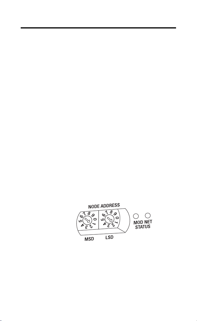
Set the Node Address on the Base Block
Each base block comes with its internal program set for node
address 63. To reset the node address, adjust the switches on
the front of the block. The two switches are most significant
digit (MSD) and least significant digit (LSD). The switches can
be set between 00 and 63.
The base block reads the rotary switches at power up only.
Switch settings between 64 and 99 cause the block to use the
last valid node address stored internally
.
Example: Node
Address is set at 11
The node address may also be set through RSNetWorx for
DeviceNet or a similar configuration tool. When software
configuration is used for the node address, the switches must
be set between 64 and 99.
Publication 1790-IN011B-EN-P - April 2003
Page 6

6
WARNING
!
WARNING
!
Mount the Base Block
You can mount the base block to a panel or DIN rail. We
recommend that you ground the panel or DIN rail before
mounting the block.
IMPORTANT
Panel Mounting
1. Place the block against the panel where you want to
mount it.
2. Gently pull and position the expansion cover to the left.
3. Place a center punch, nail or similar device through the
mounting holes in the block and make two marks on
the panel (lower left and upper right corners of the
module).
4. Remove the block and drill two holes in the panel to
accommodate each of the mounting screws.
The RTD and thermocouple base blocks do not
support any expansion blocks.
When used in a Class I, Division 2,
hazardous location, this equipment must be
mounted in a suitable enclosure with the
proper wiring method that complies with
the governing electrical codes.
Publication 1790-IN011B-EN-P - April 2003
Page 7
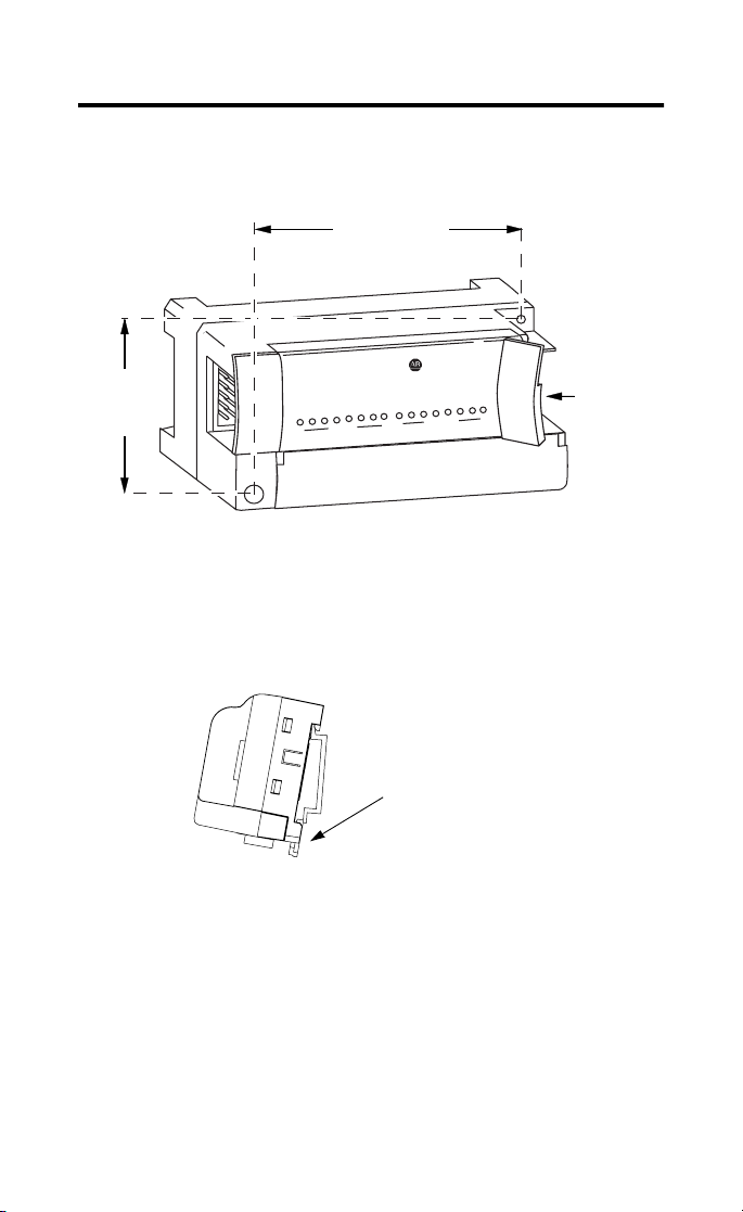
5. Replace the block on the panel and place a screw
through each of the two mounting holes. Tighten the
screws until the block is firmly in place.
95 mm
3.74 in
CompactBlock LDX
1790-16BVOX
41 mm
1.6 in
EXPANSION UNIT
0
0
7
16 INPUTS-DCPOWER
7
Expansion
Cover
DIN Rail Mounting
1. Hook the top slot of the block over the DIN Rail.
2. Pull down on the locking lever while pressing the block
against the rail.
7
f
Locking Lever
3. Push up on the locking lever to secure the block to the
rail when block is flush against the rail.
Publication 1790-IN011B-EN-P - April 2003
Page 8
8
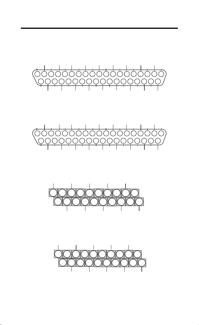
Wire the Terminal Blocks
The following figures show how to wire the terminal blocks.
1790D-4R0 RTD Input Module D-Shell Wiring
CH1_B
10
29
COM
CH1_B
10
29
NC
NC
11
CH3_B
CH3_A
11
10
CH3_B
NC
28
NC
28
COM
12
9
COM
9
13
12
NC
8
27
NC
8
27
NC
14
COM
NC
13
CH2_B
CH2_A
CH3_A
7
6
26
24
25
COM
COM COM COM
COM
CH2_B
CH2_A
CH3_A
7
6
26
24
25
NC
NC NC NC
NC
NC
NC
17
15
18
16
NC
NC
NC
NC
17
15
16
14
NC
NC
NC
5
5
NC
19
18
CH3_B
23
COM
CH3_B
23
NC
20
NC
NC
19
4
4
20
NC
NC
NC
NC
3
1
2
22
20
21
COM
NC
NC
NC
3
1
2
22
20
21
NC
+24V
NC
NC
CH0_B
+24V
19
37
GND
18
36
GND
+24V
17
35
GND
NC
16
15
34
33
NC
NC
CH0_A
14
32
NC
13
COM
CH1_A
11
12
30
31
COM
COM
• Wire pins 17, 18, 19 to Field Power (+) 24Vdc
Wire pins 35, 36, 37 to Field Power (-) GND
1790D-4T0 Thermocouple Module D-Shell Wiring
+24V
NC
NC
CH0_B
+24V
19
37
GND
18
36
GND
+24V
17
35
GND
NC
16
15
34
33
NC
NC
CH0_A
14
32
NC
CH1_A
11
13
12
30
31
NC
NC
• Wire pins 17, 18, 19 to Field Power (+) 24Vdc
Wire pins 35, 36, 37 to Field Power (-) GND
1790D-T4RO RTD Input Module Terminal Block Wiring
+24V
CH0_A
1
2
GND
CH1_A
3
CH0_B
5
4
CH1_B
COM
6
CH2_A
7
8
COM
CH3_A
9
10
CH2_B
• Wire pin 1 to Field Power (+) 24Vdc
Wire pin 2 to Field Power (-) GND
1790D-T4T0 Thermocouple Input Module Terminal Block Wiring
+24V
CH1_A
5
4
CH1_B
6
NC
7
CH2_A
9
8
CH2_B
NC
CH0_A
1
2
GND
3
CH0_B
• Wire pin 1 to Field Power (+) 24Vdc
Wire pin 2 to Field Power (-) GND
Publication 1790-IN011B-EN-P - April 2003
Page 9

9
Connect Field Wiring
System Wiring Guidelines
Follow these guidelines when wiring your system:
• use shielded, twisted pair wire to ensure proper operation
and high immunity to electrical noise
• to limit noise, locate RTD and resistance device signal wires
as far away as possible from power lines, load lines and
other sources of electrical noise, such as hard-contact
switches, relays and AC motor drives
• under normal conditions, the drain wire and shield junction
should be connected to earth ground, via a panel or DIN rail
mounting screw at the block end
• keep shield connection to ground as short as possible
• to ensure optimum accuracy, limit overall cable impedance
by keeping the cable as short as possible. Locate the I/O
system as close to your field devices as your application will
permit.
RTD Wiring Guidelines
Since the operating principle of the RTD module is
based on the measurement of resistance, give special
consideration when selecting the input cable. For 2-wire
or 3-wire configurations, select a cable that has
consistent impedance throughout its entire length.
Publication 1790-IN011B-EN-P - April 2003
Page 10

10
IMPORTANT
The RTD block requires three wires to
compensate for lead resistance error. We
recommend that you do not use 2-wire
RTDs if long cable runs are required, as it
reduces the accuracy of the system.
However, if a 2-wire configuration is
required, reduce the effect of the lead
wire resistance by using a lower-gauge
wire for the cable (for example, use AWG
#16 instead of AWG #24). The block’s
terminal strip accepts AWG #14 gauge
wire.
When using a 3-wire configuration, the block
compensates for resistance error due to lead wire length.
For example, in a 3-wire configuration, the block reads
the resistance due to the length of the wires and assumes
that the resistance of the other wire is equal. If the
resistance of the individual lead wires are much
different, an error may exist. The closer the resistance
values are to each other, the greater the amount of error
is eliminated.
IMPORTANT
To ensure temperature or resistance value
accuracy, the resistance difference of the
cable lead wires must be equal to or less
than 0.01 ohm.
Publication 1790-IN011B-EN-P - April 2003
Page 11

11
To ensure that the lead values match as closely as
possible:
• keep lead resistance as small as possible and less than
25 ohms
• use quality cable that has a small tolerance impedance
rating
• use a heavy-gauge lead wire which has less resistance
per foot
RTD Wiring Configurations
Three configurations of RTDs can be connected to the
blocks:
• 2-wire RTD, which is composed of an RTD EXC
(excitation) lead wire and a RTN (return) wire
• 3-wire RTD, which is composed of a Sense and 2 RTD
lead wires (RTD EXC and RTN)
• 4-wire RTD, which is composed of a Sense and 2 RTD
lead wires (RTD EXC and RTN). The second sense
wire of a 4-wire RTD is left open.
2-Wire RTD Configuration
Add Jumper
CH0_A
CH0_B
COM
Cable Shield (to Ground)
RTD EXC RTD EXC
Return Return
Publication 1790-IN011B-EN-P - April 2003
Page 12

12
3-Wire RTD Configuration
Cable Shield (to Ground)
CH0_A
CH0_B
COM
RTD EXC
Sense
Return
RTD EXC
Sense
Return
4-Wire RTD Configuration
Leave this sensor wire open
RTD EXC
Sense
Return
CH0_A
CH0_B
COM
Cable Shield (to Ground)
RTD EXC
Sense
Return
Wiring Resistance Devices (Potentiometers)
Potentiometer wiring requires the same type of cable as
that for the RTD. Potentiometers can be connected to the
module as a 2-wire or 3-wire connection as shown in the
following figures:
2-Wire Potentiometer Interconnection
Add Jumper
CH0_A
CH0_B
COM
Add Jumper
CH0_A
CH0_B
COM
Cable Shield (to Ground)
RTD EXC
Return
Cable Shield (to Ground)
RTD EXC
Return
Publication 1790-IN011B-EN-P - April 2003
Potentiometer
Potentiometer
Page 13

3-Wire Potentiometer Interconnection
TIP
r
The potentiometer wiper arm can be
connected to either the EXC or return
terminal, depending on whether you
want increasing or decreasing
resistance.
Cable Shield (to Ground)
CH0_A
CH0_B
COM
CH0_A
CH0_B
COM
RTD EXC
Return
Cable Shield (to Ground)
RTD EXC
Sense
Return
13
Potentiomete
Run Return and sense wires from
the module to potentiometer terminal
and tie terminal to one point
Potentiometer
Run Return and sense wires from
the module to potentiometer terminal
and tie terminal to one point
Publication 1790-IN011B-EN-P - April 2003
Page 14

14
WARNING
!
WARNING
!
Connect the DeviceNet Cable
Follow these procedures when connecting the DeviceNet
cable to the base block.
The required DeviceNet connector is not supplied with the
block - you must purchase it separately. There are three types
of connectors that you can order directly from Rockwell
Automation or your local distributor:
• 1799-DNETCON - 5-position open style connector
• 1799-DNETSCON - 5-position open style connector with
locking screws
• 1799-DNC5MMS - 5-position open style to 5-pin micro
male connector with locking screws
If you connect or disconnect the DeviceNet
cable with power applied to this module or
any device on the network, an electrical arc
can occur. This could cause an explosion in
hazardous location installations.
Be sure that power is re moved or the area is
nonhazardous before proceeding.
Connect the DeviceNet wiring (drop line) to one of the
DeviceNet connectors as shown below. A color-coded wiring
diagram is also printed next to the connector on the left side
of the module
CompactBlock LDX
Wiring Diagram for
1799-DNETCON
1790D-8BV8V
8 INPUTS/8OUTPUTS-DC POWER
7
0
7
0
V+ Red
Can_H White
Drain/Shield
Can_L Blue
V- Black
V+ Red
V- Black
Wiring Diagram for
1799-DNC5MMS
Publication 1790-IN011B-EN-P - April 2003
Drain/Shield
Can_H White
Can_L Blue
Page 15

15
Once you have properly wired the drop line to the connector,
attach the connector to the block. If applicable, use the
locking screws on the connector to fasten it to the block.
I/O Memory Mapping
1790D-4R0, -T4R0 Input Data File
Word Bit Position
1514131211109876543210
0 RTD Input Data Channel 0
1 RTD Input Data Channel 1
2 RTD Input Data Channel 2
3 RTD Input Data Channel 3
4 Not Used S11 S10 S9 S8 Not Used S3 S2 S1 S0
Word/Bit Descriptions for 1790D-4R0, -T4R0 RTD Module
Word Decimal Bit Description
Read Word 0 Bits 00-15 Channel 0 input data
Read Word 1 Bits 00-15 Channel 1 input data
Read Word 2 Bits 00-15 Channel 2 input data
Read Word 3 Bits 00-15 Channel 3 input data
Read Word 4
Bits 00-03 Underrange for individual channels - Bit 00 corresponds to
Bits 04-07 Not used: Set to 0
Bits 08-11 Overrange for individual channels - Bit 08 corresponds to
Bits 12-15 Not used: Set to 0
input channel 0, bit 01 corresponds to input channel 1 and
so on.
When set (1) the input signal is below the input channel’s
minimum range.
input channel 0, bit 09 corresponds to input channel 1 and
so on.
When set (1) the input signal is above the input channel’s
maximum range, or open RTD is detected.
Publication 1790-IN011B-EN-P - April 2003
Page 16

16
1790D-4T0, -T4T0 Input Data File
Word Bit Position
1514131211109876543210
0 Thermocouple Input Data Channel 0
1 Thermocouple Input Data Channel 1
2 Thermocouple Input Data Channel 2
3 Thermocouple Input Data Channel 3
4 Not Used S11 S10 S9 S8 Not Used S3 S2 S1 S0
Word/Bit Descriptions for 1790D-4T0, -T4T0 Thermocouple Module
Word Decimal Bit Description
Read Word 0 Bits 00-15 Channel 0 input data
Read Word 1 Bits 00-15 Channel 1 input data
Read Word 2 Bits 00-15 Channel 2 input data
Read Word 3 Bits 00-15 Channel 3 input data
Read Word 4
Bits 00-03 Underrange for individual channels - Bit 00 corresponds to
Bits 04-07 Not used: Set to 0
Bits 08-11 Overrange for individual channels - Bit 08 corresponds to
Bits 12-15 Not used: Set to 0
input channel 0, bit 01 corresponds to input channel 1 and
so on.
When set (1) the input signal is below the input channel’s
minimum range.
input channel 0, bit 09 corresponds to input channel 1 and
so on.
When set (1) the input signal is above the input channel’s
maximum range, or open thermocouple is detected.
Publication 1790-IN011B-EN-P - April 2003
Page 17

Troubleshoot with the Indicators
The 1790D I/O block has the following indicators:
• module status
• network status
• I/O status
Mod/Net Status Indicator
LED Indicator: Status: Description:
Module Status Solid Red Unrecoverable fault in base unit
Flashing Red Recoverable fault
Solid Green Normal operation - OK
Flashing Green Standby
Off No power
LED Indicator: Status: Description:
Network Status Solid Red Unrecoverable communication fault
Flashing Red Recoverable communication fault
Solid Green Communication path complete - OK
Flashing Green Communication path incomplete
Off Device not online or not powered
17
I/O Channel LED Status Indicator
Status: Description:
Flashing Green/Red Power up
Off Off line
Red On line and no field power
Red DeviceNet connection and no field power
Flashing Red Field power and open wire
Green Field power and valid input
Flashing Red Input over range
Flashing Red Input under range
Flashing Red Recoverable fault
Publication 1790-IN011B-EN-P - April 2003
Page 18

18
DeviceNet RTD and Thermocouple Base Block Specifications
The following table contains specifications that are common to
all of the blocks in this document. Individual base block
specifications are detailed after this table.
Environmental Specifications
Operating Temperature 0 to 55°C (32 to 131°F) - Analog I/O
Storage Temperature -40 to 85°C (-40 to 185°F)
Relative Humidity 5-90% non-condensing
Operating Altitude 2000m
Vibration 2g @ 10-500Hz
Shock
Operating
Non-operating
Emissions Group 1, Class A
ESD Immunity 8kV air discharges
Radiated RF Immunity 10V/m with 1kHz sine-wave 80%AM from 80MHz to 1000MHz
EFT/B Immunity 1kV @ 5kHz on power ports
Surge Transient Immunity +
Conducted RF Immunity 10Vrms with 1kHz sine-wave 80%AM from 150kHzto 80MHz
Enclosure Type Rating None (open style)
Mounting DIN rail or screw
Dimensions 52x104x42mm (2.03x4.07x1.64in)
Weight 0.3lb (0.1kg)
IEC 60068-2-1 (Test Ad, Operating Cold),
IEC 60068-2-2 (Test Bd, Operating Dry Heat),
IEC 60068-2-14 (Test Nb, Operating Thermal Shock)
IEC 60068-2-1 (Test Ab, Un-packaged Non-operating Cold),
IEC 60068-2-2 (Test Bb, Un-packaged Non-operating Dry
Heat),
IEC 60068-2-14 (Test Na, Un-packaged Non-operating Thermal
Shock)
IEC 60068-2-30 (Test Db, Un-packaged Non-operating)
IEC60068-2-6 (Test Fc, Operating)
10g
30g
EC60068-2-27 (Test Ea, Unpackaged Shock)
CISPR 11
IEC 61000-4-2
10V/m with 200Hz 50% Pulse 100%AM @ 900Mhz
IEC 61000-4-3
+
2kV @ 5kHz on signal ports
+
2kV @ 5kHz on communications ports
IEC 61000-4-4
1kV line-line(DM) and +2kV line-eath(CM) on signal ports
2kV line-earth(CM) on shielded ports
+
EC 61000-4-5
IEC 61000-4-6
Publication 1790-IN011B-EN-P - April 2003
Page 19

19
DeviceNet Specifications
Network protocol I/O Slave messaging:
Network length 500 meters maximum @ 125Kbps
Indicators 1 red/green module status
Number of nodes 64 maximum - rotary switch type node address setting
Communication rate 125Kbps, 250Kbps, 500Kbps - auto baud rate selection
Isolation Type test 1250Vac rms for 60 seconds between field power and
Wiring Refer to publication DN-6.7.2
General Specifications
Wiring Category
Product
Certifications
(when product is
marked)
1
Refer to publication 1770-4.1, Programmable Controller Wiring and Grounding Guidelines.
2
See the Product Certification link at www.ab.com for Declarations of Conformity, Certificates, and other
certification details.
- Poll command
- Bit Strobe command
- Cyclic command
- COS command
100 meters maximum @ 500Kbps
1 red/green network status
DeviceNet (I/O to logic)
1
2
c-UL-us UL Listed for Class I, Division 2 Group A,B,C,D Hazardous
Locations, certified for U.S. and Canada
2
CE
with:
European Union 89/336/EEC EMC Directive, compliant
EN 50082-2; Industrial Immunity
EN 61000-6-4; Industrial Emissions
EN61326; Meas./Control/Lab., Industrial Requirements
EN 61000-6-2; Industrial Immunity
2
C-Tick
Australian Radiocommunications Act, compliant with:
AS/NZS CISPR11; Industrial Emissions
ODVA ODVA conformance tested to DeviceNet specifications
Publication 1790-IN011B-EN-P - April 2003
Page 20

20
4-Channel Input RTD Base Module Specification
1790D-4R0, 1790D-T4R0
Inputs per module 4 channel, RTD/Resistance Input
Input Range 1-625
Sensors Supported Sensor Type Degree Counts Resolution
Resistance 100m
Resistance 10mΩ 1 to 327Ω 100 to
100ohm Pt/α =0.00385 -200 to
200ohm Pt/
500ohm Pt/α =0.00385 -200 to
100ohm Pt/
200ohm Pt/α =0.003916 -200 to
500ohm Pt/
100ohm Nickel -60 to
120ohm Nickel -80 to
200ohm Nickel -60 to
500ohm Nickel -60 to
Resolution 16 bits across 625ohms, 0.1°C/bit or 0.1°F/bit (RTD Sensors)
20bit Sigma-Delta modulation converter
Data Format 16 bit Integer (2’s compliment)
Module Scan Time 8ms/channel @ Notch Filter = 60Hz
Overall accuracy 0.2% Full scale @0°C-60°C
Settable Notch Filter 10Hz (default), 25Hz, 50Hz, 60Hz, 100Hz, 250Hz, 500Hz
Open Wire Detection Out of range, open wiring
Excitation Current 1mA
Input Impedance 5M ohm
Ω 1 to 625Ω 10 to 6250 100mΩ
α =0.00385 -200 to
α =0.003916 -200 to
α =0.003916 -200 to
s
+850°C
+850°C
+650°C
+640°C
+640°C
+640°C
250°C
260°C
250°C
250°C
32700
-2000 to
+8500
-2000 to
+8500
-2000 to
+6500
-2000 to
+6400
-2000 to
+6400
-2000 to
+6400
-600 to
2500
-800 to
2600
-600 to
2500
-600 to
2500
10mΩ
0.1°C
0.1°C
0.1°C
0.1°C
0.1°C
0.1°C
0.1°C
0.1°C
0.1°C
0.1°C
Specifications continured on next page.
Publication 1790-IN011B-EN-P - April 2003
Page 21

General Specifications
DeviceNet Power Supply voltage - 24V dc nominal
Field Power Supply Voltage - 24Vdc nominal
Isolation I/O to logic: photocoupler isolation
Indicators 4 red/green I/O status
Wiring
1790D-4R0
1790D-T4R0
IMPORTANT: This module does not support any expansion modules.
Voltage range - 11-28.8V dc
Power dissipation - 1.2W maximum @ 28.8V dc
Voltage Range - 21.6-26.4V dc (+
Power Dissipation - 1.5W maximum @26.4V dc
Isolation voltage: Type Test 1250V ac rms for 60 seconds
DeviceNet to logic: non-isolated
Field power: non-isolated
37-pin D-Shell connector
Terminal block connector
screw torque: 7 inch pounds maximum
10%)
4-Channel Input Thermocouple Base Module Specifications
1790D-4T0, 1790D-T4T0
Inputs per module 4 channel, Thermocouple/mV Input
Input Range +
Sensors Supported Sensor Type Range Scaling
Resolution 16 bits, 0.1°C/bit or 0.1°F/bit (Thermocouple Sensors)
Data Format 16 bit Integer (2’s compliment)
Module Scan Time 140ms/channel @ Notch Filter = 60Hz
Overall accuracy 0.2% Full scale @0°C-60°C
Settable Notch Filter 10Hz (default), 25Hz, 50Hz, 60Hz, 100Hz, 250Hz, 500Hz
Open Wire Detection Out of range, open wiring
Cold Junction
Compensation Range
76.50mV
Voltage 10V -76.50 to +76.50mV -7650 to +7650
Type B 300 to 1800°C 3000 to 18000
Type E -270 to 1000°C -2700 to 10000
Type J -210 to 1200°C -2100 to 12000
Type K -270 to 1370°C -2700 to 13700
Type R -50 to 1768°C -500 to 17680
Type S -50 to 1768°C -500 to 17680
Type T -270 to 400°C -2700 to 4000
Type N -270 to 1300°C -2700 to 13000
20bit Sigma-Delta modulation converter
0 to 70°C
21
Publication 1790-IN011B-EN-P - April 2003
Page 22

22
Input Impedance 5M ohm
General Specifications
DeviceNet Power Supply voltage - 24V dc nominal
Field Power Supply Voltage - 24Vdc nominal
Isolation I/O to logic: photocoupler isolation
Indicators 4 red/green I/O status
Wiring
1790D-4T0
1790D-T4T0
IMPORTANT: This module does not support any expansion modules.
Voltage range - 11-28.8V dc
Power dissipation - 1.2W maximum @ 28.8V dc
Voltage Range - 21.6-26.4V dc (+
Power Dissipation - 1.5W maximum @26.4V dc
Isolation voltage: Type Test 1250V ac rms for 60 seconds
DeviceNet to logic: non-isolated
Field power: non-isolated
37-pin D-Shell connector
Terminal block connector
screw torque: 7 inch pounds maximum
10%)
Publication 1790-IN011B-EN-P - April 2003
Page 23

23
IMPORTANT
Input and output wiring must be in accordance
with Class 1, Division 2 wiring methods and in
accordance with the authority having jurisdiction.
The following information applies
when operating this equipment in
hazardous locations:
Products marked “CL I, DIV 2, GP A, B, C, D” are
suitable for use in Class I Division 2 Groups A,
B, C, D, Hazardous Locations and nonhazardous
locations only. Each product is supplied with
markings on the rating nameplate indicating the
hazardous location temperature code. When
combining products within a system, the most
adverse temperature code (lowest “T” number)
may be used to help determine the overall
temperature code of the system. Combinations
of equipment in your system are subject to
investigation by the local Authority Having
Jurisdiction at the time of installation.
EXPLOSION HAZARD
• Do not disconnect
WARNING
!
equipment unless
power has been
removed or the area
is known to be
nonhazardous.
• Do not disconnect
connections to this
equipment unless
power has been
removed or the area
is known to be
nonhazardous.
Secure any external
connections that
mate to this
equipment by using
screws, sliding
latches, threaded
connectors, or other
means provided
with this product.
• Substitution of
components may
impair suitability for
Class I, Division 2.
• If this product
contains batteries,
they must only be
changed in an area
known to be
nonhazardous.
Informations sur l’utilisation de cet
équipement en environnements
dangereux :
Les produits marqués "CL I, DIV 2, GP A, B, C, D" ne
conviennent qu’à une utilisation en environnements
de Classe I Division 2 Groupes A, B, C, D dangereux
et non dangereux. Chaque produit est livré avec des
marquages sur sa plaque d’identification qui
indiquent le code de température pour les
environnements dangereux. Lorsque plusieurs
produits sont combinés dans un système, le code de
température le plus défavorable (code de
température le plus faible) peut être utilisé pour
déterminer le code de température global du
système. Les combinaisons d’équipements dans le
système sont sujettes à inspection par les autorités
locales qualifiées au moment de l’installation.
RISQUE D’EXPLOSION
• Couper le courant ou
AVERTISSEMENT
!
s’assurer que
l’environnement est
classé non dangereux
avant de débrancher
l'équipement.
• Couper le courant ou
s'assurer que
l’environnement est
classé non dangereux
avant de débrancher
les connecteurs. Fixer
tous les connecteurs
externes reliés à cet
équipement à l'aide
de vis, loquets
coulissants,
connecteurs filetés ou
autres moyens fournis
avec ce produit.
• La substitution de
composants peut
rendre cet
équipement inadapté
à une utilisation en
environnement de
Classe I, Division 2.
• S’assurer que
l’environnement est
classé non dangereux
avant de changer les
piles.
Publication 1790-IN011B-EN-P - April 2003
Page 24

This product has been tested at an Open Device Vendors
Association, Inc. (ODVA) authorized independent test
laboratory and found to comply with ODVA Conformance
Test. Please contact the ODVA website (http://www.odva.org)
for listing of products tested by ODVA independent test labs
for further details.
CompactBlock LDX and RSNetWorx for DeviceNet are trademarks of Rockwell Automation.
DeviceNet is a trademark of Open DeviceNet Vendor Association.
Publication 1790-IN011B-EN-P - April 2003 PN20957657-64
Supersedes Publication 1790-IN011A-EN -P - January 2002
© 2 003 Roc kw ell Automation. Printed in USA
 Loading...