

Page 1
Installation Instructions
PROFIBUS DP Digital Base Terminal
Block CompactBlock LDX I/O
(Cat. Nos. 1790P-T8BV8V, -T8BV8B, -T0W6)
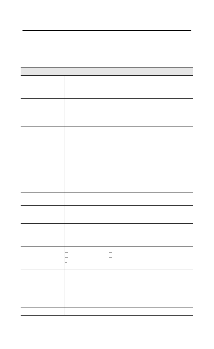
What This Document Describes
This document describes how to install your PROFIBUS DP
CompactBlock LDX I/O.
For information on: Refer to page:
GSD File Requirements below
Important User Information 2
Installing CompactBlock LDX I/O 5
Wiring the Terminal Blocks 9
Wiring the PROFIBUS Connector 10
Troubleshooting 12
Specifications 13
GSD File Requirements
Current functionality of PROFIBUS DP CompactBlock LDX I/O
blocks requires GSD files.
These files are easy to install and are available online at:
www.ab.com/networks/gsd/
1PRE Publication 1790-IN009B-EN-P - April 2003
Page 2

2
Important User Information
Because of the variety of uses for the products described in
this publication, those responsible for the application and use
of these products must satisfy themselves that all necessary
steps have been taken to assure that each application and use
meets all performance and safety requirements, including any
applicable laws, regulations, codes and standards. In no event
will Rockwell Automation be responsible or liable for indirect
or consequential damage resulting from the use or application
of these products.
Any illustrations, charts, sample programs, and layout
examples shown in this publication are intended solely for
purposes of example. Since there are many variables and
requirements associated with any particular installation,
Rockwell Automation does not assume responsibility or
liability (to include intellectual property liability) for actual use
based upon the examples shown in this publication.
Allen-Bradley publication SGI-1.1, Safety Guidelines for the
Application, Installation and Maintenance of Solid-State
Control (available from your local Rockwell Automation
office), describes some important differences between
solid-state equipment and electromechanical devices that
should be taken into consideration when applying products
such as those described in this publication.
Reproduction of the contents of this copyrighted publication,
in whole or part, without written permission of Rockwell
Automation, is prohibited.
Throughout this publication, notes may be used to make you
aware of safety considerations. The following annotations and
their accompanying statements help you to identify a potential
hazard, avoid a potential hazard, and recognize the
consequences of a potential hazard
Publication 1790-IN009B-EN-P - April 2003
Page 3
3
IMPORTANT
WARNING
!
ATTENTION
!
ATTENTION
!
Identifies information about practices or
circumstances that can cause an explosion in a
hazardous environment, which may lead to
personal injury or death, property damage, or
economic loss.
Identifies information about practices or
circumstances that can lead to personal injury or
death, property damage, or economic loss.
Identifies information that is critical for
successful application and understanding of the
product.
Preventing Electrostatic Discharge
This equipment is sensitive to electrostatic
discharge, which can cause internal damage and
affect normal operation. Follow these guidelines
when you handle this equipment:
• Touch a grounded object to discharge
potential static.
• Wear an approved grounding wriststrap.
• Do not touch connectors or pins on
component boards.
• Do not touch circuit components inside the
equipment.
• If available, use a static-safe workstation.
• When not in use, store the equipment in
appropriate static-safe packaging.
Publication 1790-IN009B-EN-P - April 2003
Page 4

4
ATTENTION
!
Environment and Enclosure
This equipment is intended for use in a Pollution
Degree 2 industrial environment, in overvoltage
Category II applications (as defined in IEC
publication 60664-1), at altitudes up to 2000
meters without derating.
This equipment is considered Group 1, Class A
industrial equipment according to IEC/CISPR
Publication 11. Without appropriate precautions,
there may be potential difficulties ensuring
electromagnetic compatibility in other
environments due to conducted as well as
radiated disturbance.
This equipment is supplied as “open type”
equipment. It must be mounted within an
enclosure that is suitably designed for those
specific environmental conditions that will be
present and appropriately designed to prevent
personal injury resulting from accessibility to live
parts. The interior of the enclosure must be
accessible only by the use of a tool. Subsequent
sections of this publication may contain
additional information regarding specific
enclosure type ratings that are required to
comply with certain product safety certifications.
NOTE: See NEMA Standards publication 250
and IEC publication 60529, as applicable, for
explanations of the degrees of protection
provided by different types of enclosure. Also,
see the appropriate sections in this publication,
as well as the Allen-Bradley publication 1770-4.1
("Industrial Automation Wiring and Grounding
Guidelines"), for additional installation
requirements pertaining to this equipment.
Publication 1790-IN009B-EN-P - April 2003
Page 5
5
Installing CompactBlock LDX I/O
Follow these steps to install the base block:
1. Set the station address on the base block.
2. Mount the base block.
3. Mount the optional expansion blocks.
4. Wire the terminal blocks.
5. Connect the PROFIBUS connector.
6. Connect power to the block.
These steps are explained in detail in the following
procedures.
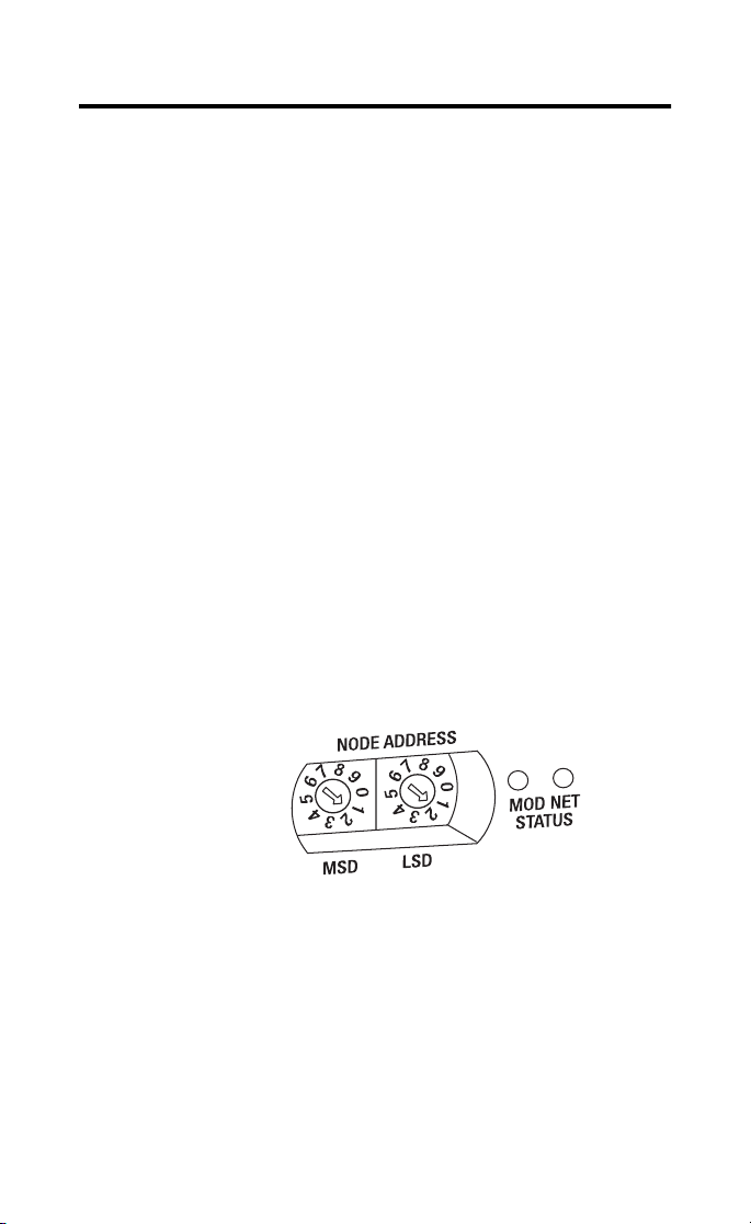
Set the Station Address on the Base Block
To set the station address, adjust the switches on the front of
the base block. The two switches are most significant digit
(MSD) and least significant digit (LSD). The switches can be
set between 00 and 99.
The base block reads the rotary switches at power-up only
Example: Station
Address is set at 11
Publication 1790-IN009B-EN-P - April 2003
.
Page 6

6
WARNING
!
Mount the Base Block
You can mount the base block to a panel or DIN rail. We
recommend that you ground the panel or DIN rail before
mounting the base block.
When used in a Class I, Division 2, hazardous
location, this equipment must be mounted in a
suitable enclosure with the proper wiring
method that complies with the governing
electrical codes.
Panel Mounting
1. Place the base block against the panel where you want
to mount it.
2. Gently pull and position the expansion cover to the left.
3. Place a center punch, nail or similar device through the
mounting holes in the base block and make two marks
on the panel (lower left and upper right corners of the
base block).
4. Remove the base block and drill two holes in the panel
to accommodate each of the mounting screws.
Publication 1790-IN009B-EN-P - April 2003
Page 7

7
5. Replace the base block on the panel and place a screw
through each of the two mounting holes. Tighten the
screws until the base block is firmly in place.
109.5 mm
4.3 in
42.5 mm
1.7 in
DIN Rail Mounting
1. Hook the top slot of the base block over the DIN Rail.
2. Pull down on the locking lever while pressing the base
block against the rail.
f
Locking Lever
3. When the base block is flush against the rail, push up
on the locking lever to secure the base block to the rail.
Expansion
Cover
Publication 1790-IN009B-EN-P - April 2003
Page 8

8
Compact
PULL
PULL
Compact
PULL
PULL
Compact
PULL
PULL
Compact
PULL
PULL
Compact
PULL
PULL
Compact
PULL
PULL
Compact
PULL
PULL
Mount the Optional Expansion Blocks
IMPORTANT
The analog base blocks can accommodate a
maximum of two discrete expansion blocks.
The RTD and thermocouple base blocks do
not support any expansion blocks.
Mount the expansion block by connecting it to a
previously-installed CompactBlock LDX I/O base or expansion
block.
Beginning with the base block, you can mount your
expansion blocks either horizontally or vertically:
• horizontally (left to right) - add expansion blocks in an
end-to-end configuration
• vertically (up or down) - add expansion blocks either up or
down in a back-to-back configuration. In this configuration,
you must use the optional 15cm ribbon cable
(1790-15CMCBL) and alternately position the blocks in a
right-side up, upside-down fashion.
Compact
Block LDX
Compact
Block LDX
EXPANSION UNIT
PULL
RIGHT SIDE UP
Horizontal mounting
EXPANSION UNIT
PULL
PULL
RIGHT SIDE UP
Vertical mounting
Compact
Block LDX
PULL
PULL
PULL
PULL
Compact
EXPANSION UNIT
RIGHT SIDE UP
UPSIDE DOWN
Compact
Block LDX
Compact
EXPANSION UNIT
RIGHT SIDE UP
EXPANSION UNIT
PULL
RIGHT SIDE UP
Block LDX
PULL
EXPANSION UNIT
Block LDX
PULL
Compact
Block LDX
The longer expansion cable
(1790-15CMCBL) will allow
up to 7cm of space in between
blocks.
PULL
EXPANSION UNIT
PULL
PULL
PULL
RIGHT SIDE UP
You can mount your blocks on a panel or DIN rail as
described in the previous section.
Publication 1790-IN009B-EN-P - April 2003
Page 9

Wire the Terminal Block
The following figures show the wiring information for the
terminal blocks.
1790P-T8BV8V Input/Output Base Block Wiring Diagram
IN0
1
• Sinking inputs - wire COM (pin 9) to Field Power (-) GND
Sourcing inputs - wire COM (pin 9) to Field Power (+) 24V dc
Note: both COM (pins 9 and 10) are in te rna ll y connected.
• Sinking outputs -wire VDC (pin 11) to Field Power (+) 24Vdc,
wire GND (pin 12) to Field Power (-) GND
1790P-T8BV8B Input/Output Base Block Wiring Diagram
IN0
1
• Sinking inputs - wire COM (pin 9) to Field Power (-) GND
Sourcing inputs - wire COM (pin 9) to Field Power (+) 24Vdc
Note: both COM (pins 9 and 10) are in te rna ll y connected.
• Sourcing outputs -wire VDC (pin 11) to Field Power (+) 24Vdc,
wire GND (pin 12) to Field Power (-) GND
2
IN1
2
IN1
IN2
IN2
IN4
COM
IN6
3
5
7
4
6
8
IN5
IN3
IN4
IN7
COM
IN6
3
5
7
4
6
8
IN5
IN3
IN7
9
9
10
COM
10
COM
VDC
11
VDC
11
12
GND
12
GND
OUT0
13
OUT0
13
OUT2
14
OUT1
OUT2
14
OUT1
15
15
OUT4
16
OUT3
OUT4
16
OUT3
17
17
OUT6
18
OUT5
OUT6
18
OUT5
19
20
OUT7
19
20
OUT7
9
1790P-T0W6 Relay Output Base Block Wiring Diagram
VDC
OUT0
NC
1
3
2
4
GND
NC
5
6
COM0
OUT2
OUT1
7
8
COM1
9
COM2
OUT3
10
11
COM3
OUT4
12
13
COM4
OUT5
15
14
• Wire VDC (pin 1) to Field Power (+) 24Vdc
Wire GND (pin 2) to Field Power (-) GND
Publication 1790-IN009B-EN-P - April 2003
16
COM5
NC
17
18
NC
NC
19
20
NC
Page 10

10
WARNING
!
Wire and Connect the PROFIBUS DP Terminal Connector
Follow these procedures when connecting the PROFIBUS DP
terminal connector to the base block.
If you connect or disconnect the PROFIBUS
cable with power applied to this module or any
device on the network, an electrical arc can
occur. This could cause an explosion in
hazardous location installations. Be sure that
power is removed or the area is nonhazardous
before proceeding.
The required PROFIBUS female 9-pin D-sub connector is not
supplied with the base block; you must purchase it separately.
Before you connect the female 9-pin D-sub connector to the
base block, make sure it is wired correctly, as shown in the
following table.
Pin Number: Name: Description:
1 shield Shield, Protective Ground
2 M24V Minus 24V Output Voltage
3 RxD/TxD-P Receive/Transmit-Data-P
4CNTR-P Control-p
5 DGND Data Ground
6VP Voltage-Plus
7 P24V Plus 24V Output Voltage
8 RxD/TxD-N Receive/Transmit-Data-N
9CNTR-N Control-N
Publication 1790-IN009B-EN-P - April 2003
Page 11

11
Once you have properly wired the connector, attach it to the
base block as shown below. Use the locking screws on the
connector to fasten it to the base block.
Module
Power Connector
(underneath module)
PROFIBUS
Green - GND
Black - COM
Red - +24Vdc
Connector
Connect Power to the Block
To apply power to the block, refer to the above illustration.
Publication 1790-IN009B-EN-P - April 2003
Page 12
12
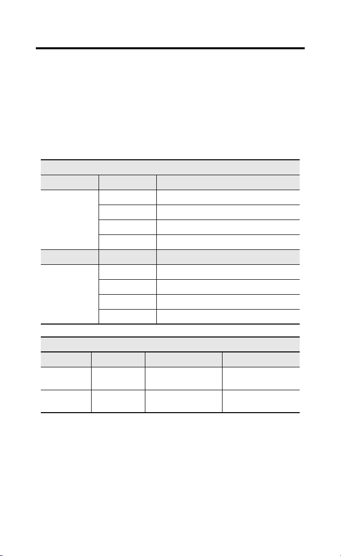
Troubleshoot with the Indicators
The base block has the following indicators:
• module status
• network status
• I/O status
Mod/Net Status Indicator
LED Indicator: Status: Description:
Module Status Solid Red Unrecoverable fault in base block
Flashing Red Unrecoverable fault in expansion unit
Solid Green Normal operation - OK
Off No power
LED Indicator: Status: Description:
Network Status Solid Red Unrecoverable communication fault
Flashing Red Recoverable communication fault
Solid Green Communication path complete - OK
Flashing Green Communication path incomplete
I/O Status Indicators
Function: LED Color: Module Illumination: Condition:
Outputs Each output:
Inputs Each Input:
Green
Green
None
Green
None
Green
Output not energized
Output energized
No valid input
Valid input
Publication 1790-IN009B-EN-P - April 2003
Page 13
13
PROFIBUS DP Digital Base Terminal Block Specifications
The following table contains specifications that are common to
all of the base blocks in this document. Individual base block
specifications are detailed after this table.
Environmental Specifications
Operating Temperature 0 to 55°C (32 to 131°F)
Storage Temperature -40 to 85°C (-40 to 185°F)
Relative Humidity 5-90% non-condensing
Operating Altitude 2000m
Vibration I2g @ 10-500Hz
Shock: Operating
Non-operating
Emissions Group 1, Class A
ESD Immunity 8kV air discharges
Radiated RF Immunity 10V/m with 1kHz sine-wave 80%AM from 80MHz to 1000MHz
EFT/B Immunity +
Surge Transient
Immunity
Conducted RF
Immunity
Enclosure Type Rating None (open style)
Mounting DIN rail or screw
Dimensions 52x118.5x42mm (2.03x4.62x1.64in)
Weight 0.3lb (0.1kg)
IEC 60068-2-1 (Test Ad, Operating Cold),
IEC 60068-2-2 (Test Bd, Operating Dry Heat),
IEC 60068-2-14 (Test Nb, Operating Thermal Shock)
IEC 60068-2-1 (Test Ab, Un-packaged Non-operating Cold),
IEC 60068-2-2 (Test Bb, Un-packaged Non-operating Dry Heat),
IEC 60068-2-14 (Test Na, Un-packaged Non-operating Thermal
Shock)
IEC 60068-2-30 (Test Db, Un-packaged Non-operating)
EC60068-2-6 (Test Fc, Operating)
I0g
30g
IEC60068-2-27 (Test Ea, Unpackaged Shock)
CISPR 11
IEC 61000-4-2
10V/m with 200Hz 50% Pulse 100%AM @ 900Mhz
IEC 61000-4-3
1kV @ 5kHz on power ports
+
2kV @ 5kHz on signal ports
2kV @ 5kHz on communications ports
+
IEC 61000-4-4
1kV line-line(DM) and +2kV line-earth(CM) on power ports
+
+
1kV line-line(DM) and +2kV line-earth(CM) on signal ports
+
2kV line-earth(CM) on shielded ports
IEC 61000-4-5
10Vrms with 1kHz sine-wave 80%AM from 150kHzto 80MHz
IEC 61000-4-6
Publication 1790-IN009B-EN-P - April 2003
Page 14

14
PROFIBUS DP Specifications
Network Protocol PROFIBUS-DP (EN50170)
Redundancy Not supported
Repeater Control
Signal
Implementation Type DPC31
Freeze Mode Supported
Sync Mode Supported
Auto Baud Rate Supported
Fail Safe Mode
Station Type Slave
FMS Support Not supported
Indicators 1 red/green module status
Number of nodes 100 maximum - rotary switch type node address setting (0-99)
Network Length/
Communication rate
Isolation Type test 1250Vac rms for 60 seconds between field power and PROFIBUS
General Specifications
Wiring Category
Product Certifications
(when product is
marked)
1
Dependent upon the scanner module being used. For example, the SST Scanner (cat. no.
SST-PFB-SLC) does not fully support Fail Safe mode as it only resets outputs to 0. You cannot define
behavior such as Hold Last State or Fault Value with the SST Scanner.
2
Refer to publication 1770-4.1, Programmable Controller Wiring and Grounding Guidelines.
3
See the Product Certification link at www.ab.com for Declarations of Conformity, Certificates and other
certification details.
• Communication of the slave with a Class 1 master
• Communication of the slave with a Class 2 master
RS485 signal
1
Supported
1 red/green network status
9.6Kbps @ 1000m (3280ft)
19.2Kbps @ 1000m (3280ft)
45.45Kbps @ 1000m (3280ft)
93.75Kbps @ 1000m (3280ft)
187.5Kbps @ 1000m (3280ft)
500Kbps @ 400m (1312ft)
1.5mbps @ 200m (656ft)
3mbps @ 100m (328ft)
6mbps @ 100m (328ft)
12mbps @ 100m (328ft)
(I/O to logic)
2
2
c-UL-us UL Listed for Class I, Division 2 Group A,B,C,D Hazardous
3
CE
C-Tick
European Union 89/336/EEC EMC Directive, compliant with:
EN 61000-6-4; Industrial Emissions
EN 50082-2; Industrial Immunity
EN61326; Meas./Control/Lab., Industrial Requirements
EN 61000-6-2; Industrial Immunity
European Union 73/23/EEC LVD Directive, compliant with:
EN 61131-2; Programmable Controllers
3
Australian Radiocommunications Act, compliant with:
AS/NZS CISPR11; Industrial Emissions
Locations, certified for U.S. and Canada
Publication 1790-IN009B-EN-P - April 2003
Page 15

15
DC Input/Output Combination Base Block Specifications
1790P-T8BV8V, -T8BV8B
INPUT SPECIFICATIONS
Inputs per base block 8 points non-isolated, sinking or sourcing
On-state voltage 9.6V dc minimum
On-state current 8mA maximum per point @ 28.8V dc
Off-state voltage 5V dc maximum
Nominal input impedance 4.8K
Input Signal Delay Off to On: 10ms maximum
Indicators 8 green status
Common type 8 points/2 COM (non-polarity) - 1790P-T8BV8V
OUTPUT SPECIFICATIONS
Outputs per base block 8 points non-isolated, sinking - 1790P-T8BV8V
On-state voltage 10V dc minimum
On-state voltage drop 0.5V dc maximum
On-state current 1mA minimum per channel
Off-state leakage 0.5mA maximum
Output signal delay Off to On: 0.5ms maximum
Indicators 8 green status
Output current rating Maximum 0.5A per output
Common type 8 points/2 COM - 1790P-T8BV8V
24V dc nominal
28.8V dc maximum
Ω
On to Off: 10ms maximum
8 points/2 COM (non-polarity) - 1790P-T8BV8B
8 points non-isolated, sourcing - 1790P-T8BV8B
24V dc nominal
28.8V dc maximum
On to Off: 1.0ms maximum
4.0A maximum per common
8 points/2 COM - 1790P-T8BV8B
Publication 1790-IN009B-EN-P - April 2003
Page 16

16
General Specifications
PROFIBUS Power Supply voltage - 24V dc nominal
Field Power Supply voltage - 24V dc nominal
Isolation I/O to logic: photocoupler isolation
Wiring Terminal block (M3.0)
Voltage range - 19.2-28.8V dc
Power dissipation - 1.2W maximum @ 28.8V dc
Voltage range - 10-28.8V dc
Power dissipation - 3.22W @ 28.8V dc
Isolation voltage: 1250V ac rms
PROFIBUS to logic: non-isolated
PROFIBUS power: non-isolated
- screw torque: 7 inch-pounds
maximum (use copper or copper-clad
aluminum conductors
AC/DC Relay Output Base Block Specifications
1790P-TOW6
Relay type Form A, normally open
Output voltage range (load dependent) 5-28V dc @ 2.0A resistive
Minimum load 100µA, 100mV dc per point
Maximum on-state voltage drop 0.5V @ 2.0A, resistive load, 24V dc
Initial Contact Resistance 30m ohm
Expected contact life 300K cycles resistive
Maximum off-state leakage 1.5mA maximum
Output delay time 10ms maximum on to off
Indicators 6 green status
Common type 1 point/1COM
Single pole, single throw
48V dc @ 0.8A resistive
125V ac @ 2.0A resistive
250V ac @ 2.0A resistive
100K cycles inductive
10ms maximum off to on
Publication 1790-IN009B-EN-P - April 2003
Page 17

17
General Specifications
PROFIBUS Power Supply voltage - 24V dc nominal
Field Power Supply voltage - 24V dc nominal
Isolation I/O to logic: photocoupler isolation
Wiring Terminal block (M3.0)
Voltage range - 19.2-28.8V dc
Power dissipation - 1.2W maximum @ 28.8V dc
Voltage range - 19.2-28.8V dc
Power dissipation - 1.7W @ 28.8V dc
Isolation voltage: 1250V ac rms
- screw torque: 7 inch-pounds
maximum (use copper or copper-clad
aluminum conductors
Important: Input and output wiring must be in accordance
with Class 1, Division 2 wiring methods and in
accordance with the authority having
jurisdiction.
Publication 1790-IN009B-EN-P - April 2003
Page 18

18
The following information applies
when operating this equipment in
hazardous locations:
Products marked “CL I, DIV 2, GP A, B, C, D” are
suitable for use in Class I Division 2 Groups A,
B, C, D, Hazardous Locations and nonhazardous
locations only. Each product is supplied with
markings on the rating nameplate indicating the
hazardous location temperature code. When
combining products within a system, the most
adverse temperature code (lowest “T” number)
may be used to help determine the overall
temperature code of the system. Combinations
of equipment in your system are subject to
investigation by the local Authority Having
Jurisdiction at the time of installation.
EXPLOSION HAZARD
• Do not disconnect
WARNING
!
equipment unless
power has been
removed or the area
is known to be
nonhazardous.
• Do not disconnect
connections to this
equipment unless
power has been
removed or the area
is known to be
nonhazardous.
Secure any external
connections that
mate to this
equipment by using
screws, sliding
latches, threaded
connectors, or other
means provided
with this product.
• Substitution of
components may
impair suitability for
Class I, Division 2.
• If this product
contains batteries,
they must only be
changed in an area
known to be
nonhazardous.
Informations sur l’utilisation de cet
équipement en environnements
dangereux :
Les produits marqués "CL I, DIV 2, GP A, B, C, D" ne
conviennent qu’à une utilisation en environnements
de Classe I Division 2 Groupes A, B, C, D dangereux
et non dangereux. Chaque produit est livré avec des
marquages sur sa plaque d’identification qui
indiquent le code de température pour les
environnements dangereux. Lorsque plusieurs
produits sont combinés dans un système, le code de
température le plus défavorable (code de
température le plus faible) peut être utilisé pour
déterminer le code de température global du
système. Les combinaisons d’équipements dans le
système sont sujettes à inspection par les autorités
locales qualifiées au moment de l’installation.
RISQUE D’EXPLOSION
• Couper le courant ou
AVERTISSEMENT
!
s’assurer que
l’environnement est
classé non dangereux
avant de débrancher
l'équipement.
• Couper le courant ou
s'assurer que
l’environnement est
classé non dangereux
avant de débrancher
les connecteurs. Fixer
tous les connecteurs
externes reliés à cet
équipement à l'aide
de vis, loquets
coulissants,
connecteurs filetés ou
autres moyens fournis
avec ce produit.
• La substitution de
composants peut
rendre cet
équipement inadapté
à une utilisation en
environnement de
Classe I, Division 2.
• S’assurer que
l’environnement est
classé non dangereux
avant de changer les
piles.
Allen-Bradley and CompactBlock LDX are trademarks of Rockwell Automation.
PROFIBUS DP is a trademark of PROFIBUS Trade Organization.
Publication 1790-IN009B-EN-P - April 2003
Page 19

19
Publication 1790-IN009B-EN-P - April 2003
Page 20

Publication 1790-IN009B-EN-P - April 2003 PN957782-06
Supersedes Publication 1790-IN009A-EN -P - February 2002 © 2003 Rockwell Automatio n. Printed in USA
 Loading...