

Page 1
CompactBlock LDX
I/O Thermocouple
Modules
1790D-T4T0, 1790D-4T0, 1790P-T4T0
User Manual
Page 2

Page 3
Important User Information
Because of the variety of uses for the products described in this
publication, those responsible for the application and use of these
products must satisfy themselves that all necessary steps have been
taken to assure that each application and use meets all performance
and safety requirements, including any applicable laws, regulations,
codes and standards. In no event will Rockwell Automation be
responsible or liable for indirect or consequential damage resulting
from the use or application of these products.
Any illustrations, charts, sample programs, and layout examples
shown in this publication are intended solely for purposes of
example. Since there are many variables and requirements associated
with any particular installation, Rockwell Automation does not
assume responsibility or liability (to include intellectual property
liability) for actual use based upon the examples shown in this
publication.
Allen-Bradley publication SGI-1.1, Safety Guidelines for the
Application, Installation and Maintenance of Solid-State Control
(available from your local Allen-Bradley office), describes some
important differences between solid-state equipment and
electromechanical devices that should be taken into consideration
when applying products such as those described in this publication.
Reproduction of the contents of this copyrighted publication, in
whole or part, without written permission of Rockwell Automation, is
prohibited.
Throughout this publication, notes may be used to make you aware
of safety considerations. The following annotations and their
accompanying statements help you to identify a potential hazard,
avoid a potential hazard, and recognize the consequences of a
potential hazard:
WARNING
!
ATTENTION
Identifies information about practices or
circumstances that can cause an explosion in a
hazardous environment, which may lead to personal
injury or death, property damage, or economic loss.
Identifies information about practices or
circumstances that can lead to personal injury or
death, property damage, or economic loss.
!
IMPORTANT
Identifies information that is critical for successful
application and understanding of the product.
Page 4

Rockwell Automation Support
Before you contact Rockwell Automation for technical assistance, we
suggest you please review the troubleshooting information contained
in this publication first.
If the problem persists, call your local Rockwell Automation
representative or contact Rockwell Automation in one of the following
ways:
Phone United
States/Canada
Outside United
States/Canada
Internet
If you need to contact Rockwell Automation for assistance, please
have the following information available when you call:
• a clear statement of the problem, including a description of what
the system is actually doing. Note the LED state; also note input
and output image words for the module.
• a list of remedies you have already tried
• processor type and firmware number (See the label on the
processor)
⇒
1.440.646.5800
You can access the phone number for your
country via the Internet:
1. Go to http://www.ab.com
2. Click on Product Support
(http://support.automation.rockwell.com)
3. Under Support Centers, click on Contact
Information
1. Go to http://www.ab.com
2. Click on Product Support
(http://support.automation.rockwell.com)
• hardware types in the system, including all I/O modules
• fault code if the processor is faulted
Your Questions or Comments on this Manual
If you find a problem with this manual, please notify us of it on the
enclosed How Are We Doing form.
Page 5

Overview
Installation and Wiring
Table of Contents
Important User Information . . . . . . . . . . . . . . . . . . . . . . . . . iii
Rockwell Automation Support . . . . . . . . . . . . . . . . . . . . . . . iv
Your Questions or Comments on this Manual . . . . . . . . . iv
Chapter 1
General Description . . . . . . . . . . . . . . . . . . . . . . . . . . . . . 1-1
Thermocouple/mV Inputs and Ranges . . . . . . . . . . . . . 1-2
Hardware Features . . . . . . . . . . . . . . . . . . . . . . . . . . . . . . 1-3
General Diagnostic Features . . . . . . . . . . . . . . . . . . . . . 1-4
System Overview . . . . . . . . . . . . . . . . . . . . . . . . . . . . . . . 1-4
System Operation . . . . . . . . . . . . . . . . . . . . . . . . . . . . 1-4
Module Operation - DeviceNet Example . . . . . . . . . . . . 1-5
Chapter Summary . . . . . . . . . . . . . . . . . . . . . . . . . . . . . . . 1-6
Chapter 2
Before You Begin . . . . . . . . . . . . . . . . . . . . . . . . . . . . . . . 2-1
Power Requirements . . . . . . . . . . . . . . . . . . . . . . . . . . . . . 2-1
1790D-4T0/T4T0 . . . . . . . . . . . . . . . . . . . . . . . . . . . . . 2-1
1790P-T4T0 . . . . . . . . . . . . . . . . . . . . . . . . . . . . . . . . . 2-1
General Considerations . . . . . . . . . . . . . . . . . . . . . . . . . . . 2-2
Hazardous Location Considerations . . . . . . . . . . . . . . . 2-2
Selecting a Location . . . . . . . . . . . . . . . . . . . . . . . . . . . 2-5
Protecting the Circuit Board from Contamination. . . . . . 2-6
Installing CompactBlock LDX I/O. . . . . . . . . . . . . . . . . 2-6
Set the Node Address on the DeviceNet 1790D-4T0/T4T0
Base Block . . . . . . . . . . . . . . . . . . . . . . . . . . . . . . . . . 2-6
Set the Station Address on the 1790P-T4T0 PROFIBUS DP
Base Block . . . . . . . . . . . . . . . . . . . . . . . . . . . . . . . . . 2-7
Mounting . . . . . . . . . . . . . . . . . . . . . . . . . . . . . . . . . . . . . 2-7
Mount the Base Block . . . . . . . . . . . . . . . . . . . . . . . . . 2-7
Panel Mounting . . . . . . . . . . . . . . . . . . . . . . . . . . . . . . 2-7
DIN Rail Mounting. . . . . . . . . . . . . . . . . . . . . . . . . . . . 2-8
Connect the DeviceNet Cable to the 1790D-4T0/T4T0 Base
Block . . . . . . . . . . . . . . . . . . . . . . . . . . . . . . . . . . . . . 2-9
Connect the PROFIBUS DP Terminal Connector to the
1790P-T4T0 Base Block . . . . . . . . . . . . . . . . . . . . . . . . 2-10
Connect Power to the 1790P-T4T0 Block . . . . . . . . . . . 2-11
Field Wiring Connections . . . . . . . . . . . . . . . . . . . . . . . . . 2-12
System Wiring Guidelines. . . . . . . . . . . . . . . . . . . . . . . 2-12
Wiring the Module. . . . . . . . . . . . . . . . . . . . . . . . . . . . 2-14
Wiring the Terminal Blocks . . . . . . . . . . . . . . . . . . . . . 2-15
Cold Junction Compensation . . . . . . . . . . . . . . . . . . . . . . . 2-16
Chapter Summary . . . . . . . . . . . . . . . . . . . . . . . . . . . . . . . 2-16
v Publication 1790-UM003A-EN-P - May 2002
Page 6

vi
Module Data, Status, and Channel
Configuration for DeviceNet
Chapter 3
Module Memory Map . . . . . . . . . . . . . . . . . . . . . . . . . . . . 3-1
Input Image. . . . . . . . . . . . . . . . . . . . . . . . . . . . . . . . . 3-1
Accessing Input Image File Data . . . . . . . . . . . . . . . . . . . . 3-1
Input Data File . . . . . . . . . . . . . . . . . . . . . . . . . . . . . . . . . 3-2
Input Data Values . . . . . . . . . . . . . . . . . . . . . . . . . . . . 3-2
Under-Range Flag Bits (S0 to S3) . . . . . . . . . . . . . . . . . 3-2
Over-Range Flag Bits (S8 to S11) . . . . . . . . . . . . . . . . . 3-3
Data Format . . . . . . . . . . . . . . . . . . . . . . . . . . . . . . . . . . . 3-3
Filter Frequency . . . . . . . . . . . . . . . . . . . . . . . . . . . . . . . . 3-4
Channel Step Response . . . . . . . . . . . . . . . . . . . . . . . . . . . 3-5
Channel Cutoff Frequency . . . . . . . . . . . . . . . . . . . . . . . . . 3-5
Effective Resolution. . . . . . . . . . . . . . . . . . . . . . . . . . . . . . 3-7
Cold Junction Compensation . . . . . . . . . . . . . . . . . . . . . . . 3-11
Determining Module Update Time. . . . . . . . . . . . . . . . . . . 3-12
Calculating Accuracy . . . . . . . . . . . . . . . . . . . . . . . . . . . . . 3-12
Configuring DeviceNet Thermocouple/mV Module
(1790D-4T0/T4T0). . . . . . . . . . . . . . . . . . . . . . . . . . . . . . . 3-14
Configure DeviceNet Thermocouple/mV Modules Using
RSNetWorx . . . . . . . . . . . . . . . . . . . . . . . . . . . . . . . . . . . . 3-15
Chapter Summary . . . . . . . . . . . . . . . . . . . . . . . . . . . . . . . 3-19
Diagnostics and Troubleshooting
Specifications
Chapter 4
Safety Considerations . . . . . . . . . . . . . . . . . . . . . . . . . . . . 4-1
Indicator Lights . . . . . . . . . . . . . . . . . . . . . . . . . . . . . . 4-1
Activating Devices When Troubleshooting . . . . . . . . . . 4-1
Stand Clear of the Equipment. . . . . . . . . . . . . . . . . . . . 4-2
Program Alteration. . . . . . . . . . . . . . . . . . . . . . . . . . . . 4-2
Safety Circuits . . . . . . . . . . . . . . . . . . . . . . . . . . . . . . . 4-2
Module Operation vs. Channel Operation . . . . . . . . . . . . . 4-2
Power-up Diagnostics . . . . . . . . . . . . . . . . . . . . . . . . . . . . 4-3
Module Status . . . . . . . . . . . . . . . . . . . . . . . . . . . . . . . 4-3
Network Status . . . . . . . . . . . . . . . . . . . . . . . . . . . . . . 4-3
Channel Diagnostics . . . . . . . . . . . . . . . . . . . . . . . . . . . . . 4-4
Over- or Under-Range Detection . . . . . . . . . . . . . . . . . 4-4
Open-Circuit Detection . . . . . . . . . . . . . . . . . . . . . . . . 4-4
Module Error Definition Table . . . . . . . . . . . . . . . . . . . 4-5
Channel LED Indicator Operation . . . . . . . . . . . . . . . . . . . 4-5
Appendix A
Environmental Specifications . . . . . . . . . . . . . . . . . . . . . . . A-1
DeviceNet Specifications . . . . . . . . . . . . . . . . . . . . . . . . . . A-2
PROFIBUS DP Specifications . . . . . . . . . . . . . . . . . . . . . . . A-2
General Specifications . . . . . . . . . . . . . . . . . . . . . . . . . . . . A-3
Thermocouple/mV Specifications. . . . . . . . . . . . . . . . . . . . A-4
Publication 1790-UM003A-EN-P - May 2002
Page 7

Two’s Complement Binary
Numbers
Thermocouple Descriptions
Using Thermocouple Junctions
vii
Appendix B
Positive Decimal Values . . . . . . . . . . . . . . . . . . . . . . . . . . B-1
Negative Decimal Values. . . . . . . . . . . . . . . . . . . . . . . . . . B-2
Appendix C
International Temperature Scale of 1990. . . . . . . . . . . . . . . C-1
Type B Thermocouples . . . . . . . . . . . . . . . . . . . . . . . . . . . C-1
Type E Thermocouples . . . . . . . . . . . . . . . . . . . . . . . . . . . C-3
Type J Thermocouples . . . . . . . . . . . . . . . . . . . . . . . . . . . C-5
Type K Thermocouples . . . . . . . . . . . . . . . . . . . . . . . . . . . C-7
Type N Thermocouples. . . . . . . . . . . . . . . . . . . . . . . . . . . C-9
Type R Thermocouples . . . . . . . . . . . . . . . . . . . . . . . . . . C-11
Type S Thermocouples . . . . . . . . . . . . . . . . . . . . . . . . . . C-12
Type T Thermocouples . . . . . . . . . . . . . . . . . . . . . . . . . . C-14
References . . . . . . . . . . . . . . . . . . . . . . . . . . . . . . . . . . . C-17
Appendix D
Using a Grounded Junction Thermocouple . . . . . . . . . . . . D-1
Using an Ungrounded (Isolated) Junction Thermocouple . . D-2
Using an Exposed Junction Thermocouple. . . . . . . . . . . . . D-3
Module Configuration for
PROFIBUS
Appendix E
Configure PROFIBUS Thermocouple/mV Modules (1790P-T4R0)
E-1
Configure Thermocouple/mV Modules Using the SST PROFIBUS
Configuration Tool . . . . . . . . . . . . . . . . . . . . . . . . . . . . . . E-1
Save the Configuration . . . . . . . . . . . . . . . . . . . . . . . . . . . E-7
Download the Configuration . . . . . . . . . . . . . . . . . . . . . . . E-7
Summary . . . . . . . . . . . . . . . . . . . . . . . . . . . . . . . . . . . . E-10
Glossary
. . . . . . . . . . . . . . . . . . . . . . . . . . . . . . . . . . . . . . . . . . . . G-1
Index
. . . . . . . . . . . . . . . . . . . . . . . . . . . . . . . . . . . . . . . . . . . . . I-1
Publication 1790-UM003A-EN-P - May 2002
Page 8

viii
Publication 1790-UM003A-EN-P - May 2002
Page 9

Chapter
Overview
This chapter describes the 1790D-4TO/T4TO (1790P-T4TO)
Thermocouple/mV Input module and explains how the module reads
thermocouple or millivolt analog input data. Included is:
• the module’s hardware and diagnostic features
• an overview of system and module operation
• compatibility
1
General Description
The thermocouple/mV input module supports thermocouple and millivolt
signal measurement applications that require up to four channels. It
digitally converts and stores thermocouple and/or millivolt analog data
from any combination of up to four thermocouple or millivolt analog
sensors. Each input channel is individually configurable via software for a
specific input device, and filter frequency, and provides open-circuit,
over-range and under-range detection and indication. When configured
for thermocouple inputs, the module can convert the thermocouple
readings into digital temperature readings in °C or °F. When configured
for mV inputs, the module assumes that the direct mV input signal is
linear prior to input to the module.
The data can be configured on board each module as:
engineering units x 1
The module uses a digital filter that provides high frequency noise
rejection for the input signals. The filter is programmable, allowing you
to select from seven different filter frequencies for each channel:
• 10 Hz
• 25 Hz
• 100 Hz
• 250 Hz
• 50 Hz
• 60 Hz
The module uses five input words for data and status bits. Module
configuration is stored in the module memory. The 1790D modules’
configuration is done via RSNetWorx for DeviceNet™ programming
software. See Chapter 3, Module Data, Status, and Channel Configuration
for DeviceNet , for details on module configuration. The 1790P module
configuration is explained in Appendix E.
1 Publication 1790-UM003A-EN-P
• 500 Hz
Page 10
1-2 Overview
Thermocouple/mV Inputs and Ranges
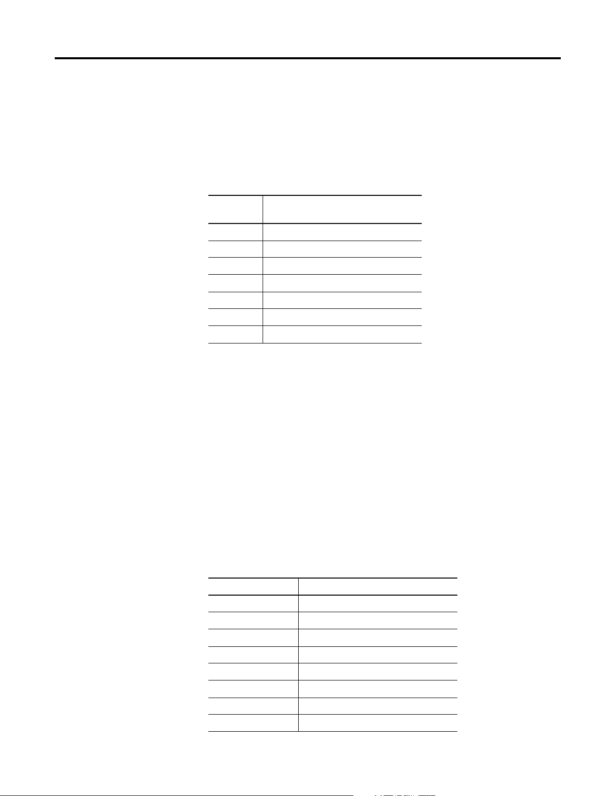
The table below defines thermocouple types and their associated
full-scale temperature ranges. The second table lists the millivolt analog
input signal ranges that each channel will support.
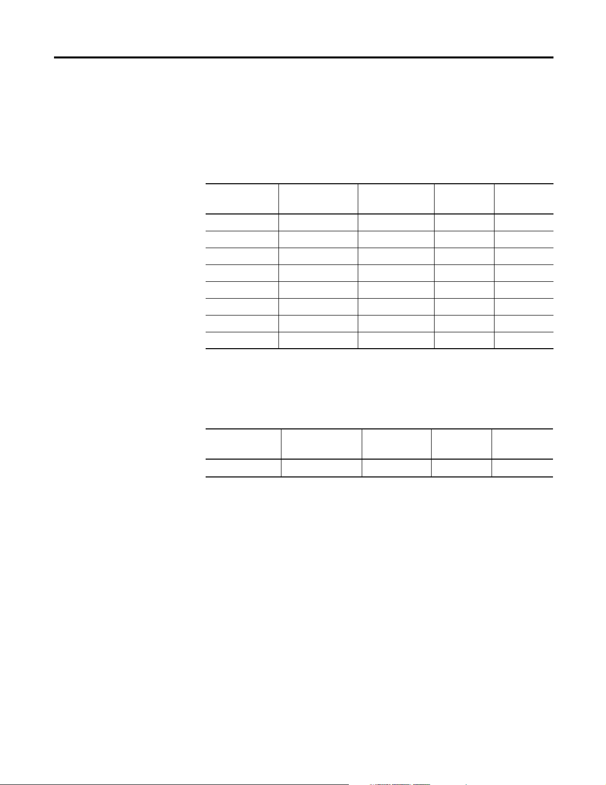
Table 1.1 Thermocouple Analog Input Signal Types
Thermocouple
Ty pe
Temperature
Range
Scaling (Counts)
Resolution
*
Accuracy**
(0 to 55°C)
B +300 to +1800°C +3000 to +18000 0.1°C ±4.2°C
E -270 to +1000°C -2700 to +10000 0.1°C ±2.5°C
J -210 to +1200°C -2100 to +12000 0.1°C ±2.8°C
K -270 to +1370°C -2700 to +13700 0.1°C ±3.3°C
R -50 to +1768°C -500 to +17680 0.1°C ±3.6°C
S -50 to +1768°C -500 to +17680 0.1°C ±3.6°C
T -270 to 400°C -2700 to 4000 0.1 °C ±1.3°C
N -270 to 1300°C -2700 to 13000 0.1°C ±3.1°C
* Filter set for 10 Hz
** Module only
Table 1.2 mV Analog Input Signal Types
Millivolt Input Range Scaling
(Counts)
10µV
* Filter set for 10 Hz
** Module only
-76.5 to +76.5 mV -7650 to +7650
Resolution
10µV 306µV
*
Accuracy
(0 to 55°C)
**
Publication 1790-UM003A-EN-P
Page 11
Overview 1-3
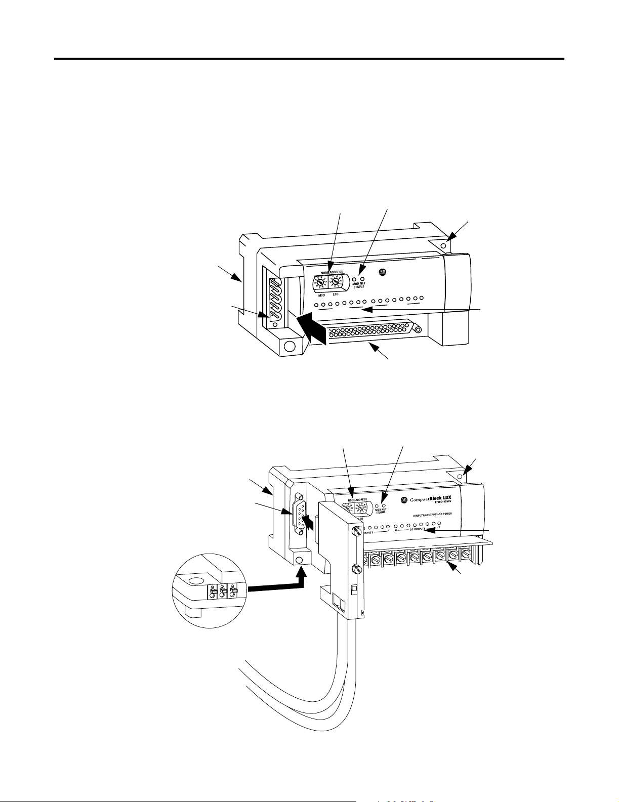
Hardware Features
DeviceNet Network
Connection
The thermocouple/mV module contains either a fixed terminal block or a
removable D-sub connector, which provides connections for four inputs
for any combination of thermocouple and mV input devices. Channels are
wired as differential inputs. The illustration below shows the hardware
features of the module.
Figure 1.1 1790D-4T0/T4T0 DeviceNet Module
Node Address
Switches
DIN Rail Slot
0
Module and Network
Status Indicators
Block LDX
Compact
S
T
U
P
IN
8
0
7
V
8
V
B
-8
D
90
17
R
E
W
O
P
C
-D
S
T
U
P
T
U
/8O
7
Thermocouple/mV Connections
(D-sub Connector shown)
Panel Mount
Hole
Thermoucouple/mV
Channel Indicators
43223
Figure 1.2 1790P-T4T0 PROFIBUS DP Module
DIN Rail Slot
PROFIBUS Network
Connector
Module Power Connector
(underneath module)
Node Address
Switches
Module and Network
Status Indicators
PROFIBUS
Connector
Panel Mount
Hole
Thermocouple/mV
Channel Indicators
Thermocouple/mV
Connections (Terminal block)
31341-M
Publication 1790-UM003A-EN-P
Page 12

1-4 Overview
Internal to the module, Cold Junction Compensation (CJC) sensors are
attached to the terminal block to enable accurate readings from each
channel. These sensors compensate for offset voltages introduced into
the input signal as a result of the cold-junction where the thermocouple
wires are connected to the module.
General Diagnostic Features
Module, network, and channel LEDs help you identify the source of
problems that may occur during power-up or during normal channel
operation. The LEDs indicate both status and power. See Chapter 4,
Diagnostics and Troubleshooting , for details on power-up and channel
diagnostics.
System Overview
The modules communicate to the controller or network scanner via the
DeviceNet™ or PROFIBUS network. The 1790D modules also receive 24V
dc power through DeviceNet. An external 24V dc auxiliary source is
required to power the 1790P module and all thermocouple/mV channels.
System Operation
At power-up, the module performs a check of its internal circuits,
memory, and basic functions. If no faults are found during power-up
diagnostics, the module status LED is turned on (green).
Once a channel is properly configured and enabled, the module
continuously converts the thermocouple or mV input to a value within the
range selected for that channel.
Each time the module reads an input channel, it tests the data for a fault
(over- or under-range or open-circuit condition). If it detects a fault, the
module sets a unique bit in the channel status word. See Input Data File
on page 3-2. The module sends two’s compliment binary converted
thermocouple/mV data out over the network. See Appendix B for a
description of two’s compliment binary numbers.
Publication 1790-UM003A-EN-P
Page 13
Input
VA2
Overview 1-5
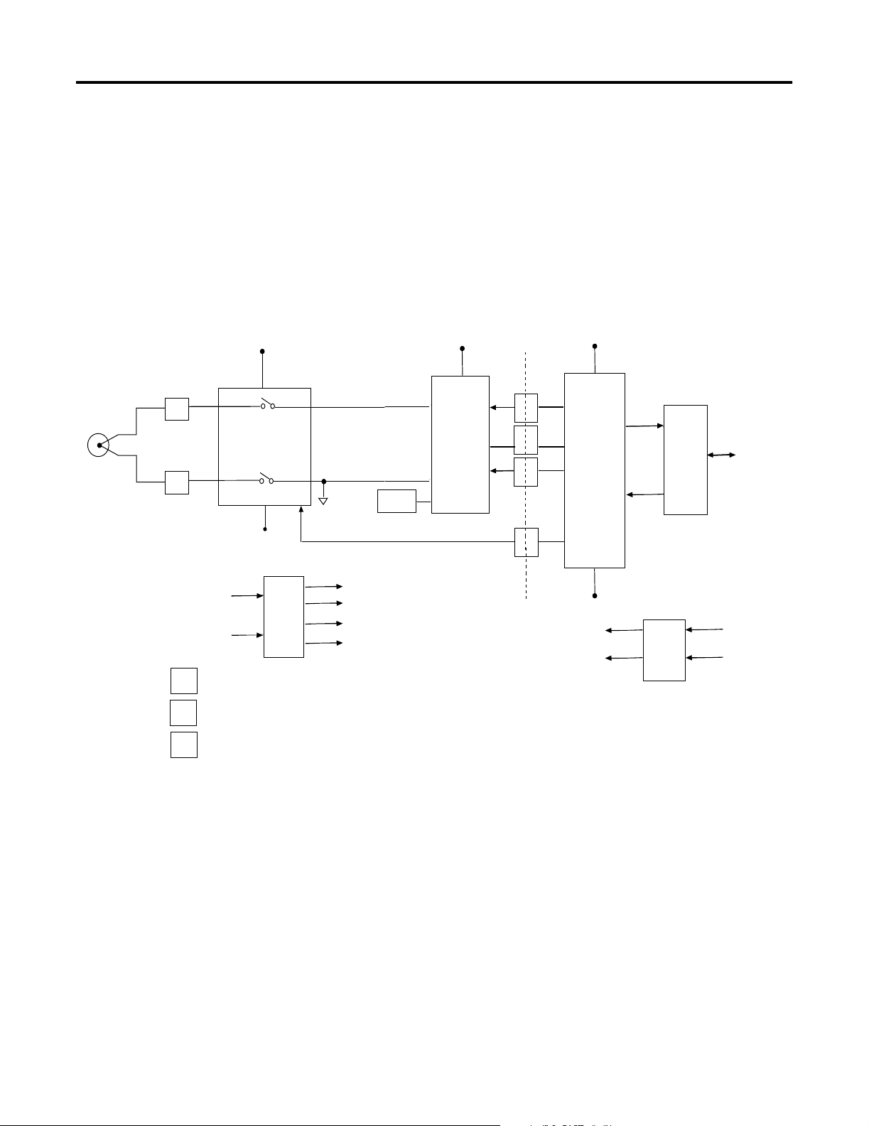
Module Operation - DeviceNet Example
When the module recieves a differential input from an analog device, the
module’s circuitry multiplexes the input into an A/D converter. The
converter reads the signal and converts it as required for the type of input.
The module also continuously samples the CJC sensors and compensates
for temperature changes at the terminal block cold junction, between the
thermocouple wire and the input channel. See the block diagram below.
Figure 1.3 Block Diagram
VA1
Optical
Isolation
Vcc
CH0
+
A
_
B
Auxiliary
24Vdc
Power
1
2
3
Multiplexer
A-GND
VA3
VDC
Analog
Power
GND
Supply
Channels 1 through 3 same as
channel 0 above.
VA1
VA2
VA3
A-GND
AIN+1
A/D
AIN-
VREFVref
Channel Select
MicroController
GND
Vcc
GND
Transmit
Receive
Transceiver
Power
Supply
Network
DeviceNet
24Vdc
Power
43309
Each channel can receive input signals from a thermocouple or millivolt
analog input device, depending upon how you configured the channel.
When configured for thermocouple input types, the module converts the
analog input voltages into cold-junction compensated and linearized
digital temperature readings. The module uses the National Institute of
Standards and Technology (NIST) ITS-90 standard for linearization for all
thermocouple types (J, K, T, E, R, S, B, N).
When configured for millivolt inputs, the module converts the analog
values directly into digital counts.
Publication 1790-UM003A-EN-P
Page 14

1-6 Overview
From the readings taken by the converter, the module sends
thermocouple or mV data through the microcontroller to the DeviceNet
network.
The PROFIBUS block diagram is similar.
Chapter Summary
In this chapter, you learned about the 1790D-4T0/T4T0 (1790P-T4T0)
thermocouple/mV module. See Chapter 2 to learn how to install and wire
the module.
Publication 1790-UM003A-EN-P
Page 15
Installation and Wiring
Chapter
2
Before You Begin
Power Requirements
This chapter tells you how to:
• determine the power requirements for the modules
• avoid electrostatic damage
• install the module
• wire the module’s terminal block
1790D-4T0/T4T0
The module receives system power from the DeviceNet network. An
auxiliary field supply provides power for the thermocouple/mV
channels.
Table 2.1 1790D-4T0/T4T0 Power Specifications
Power Specification
DeviceNet Supply voltage - 24V dc nominal
Voltage range - 11-28.8V dc
Power dissipation - 1.2W maximum @ 28.8V dc
Field Supply voltage - 24V dc nominal
Voltage range - 21.6-26.4V dc (+
Power dissipation - 1.5W maximum @ 26.4V dc
10%)
1790P-T4T0
The module requires external supplies for both system power and for
the thermocouple/mV channels.
Table 2.2 1790P-T4T0 Power Specifications
Power Specification
PROFIBUS Supply voltage - 24V dc nominal
Voltage range - 19.2-28.8V dc
Power dissipation - 2W maximum @ 28.8V dc
Field Supply voltage - 24V dc nominal
Voltage range - 21.6-26.4V dc (+
Power dissipation - 1.5W maximum @ 26.4V dc
1 Publication 1790-UM003A-EN-P - May 2002
10%)
Page 16
2-2 Installation and Wiring
General Considerations
The modules are suitable for use in a commercial or light industrial
environment when installed in accordance with these instructions.
Specifically, this equipment is intended for use in clean, dry
environments (Pollution degree 2
Over Voltage Category II
(2)
(IEC 60664-1)
(1)
) and to circuits not exceeding
(3)
.
Hazardous Location Considerations
This equipment is suitable for use in Class I, Division 2, Groups A, B,
C, D or non-hazardous locations only. The following WARNING
statement applies to use in hazardous locations.
WARNING
!
EXPLOSION HAZARD
• Substitution of components may impair suitability
for Class I, Division 2.
• Do not replace components or disconnect
equipment unless power has been switched off or
the area is known to be non-hazardous.
• Do not connect or disconnect components unless
power has been switched off or the area is known
to be non-hazardous.
• This product must be installed in an enclosure.
• All wiring must comply with N.E.C. article 501-4(b).
Publication 1790-UM003A-EN-P - May 2002
(1)
Pollution Degree 2 is an environment where, normally, only non-conductive pollution occurs except that
occasionally a temporary conductivity caused by condensation shall be expected.
(2)
Over Voltage Category II is the load level section of the electrical distribution system. At this level transient
voltages are controlled and do not exceed the impulse voltage capability of the product’s insulation.
(3)
Pollution Degree 2 and Over Voltage Category II are International Electrotechnical Commission (IEC)
designations.
Page 17
The following information applies when operating this
equipment in hazardous locations:
Products marked “CL I, DIV 2, GP A, B, C, D” are suitable for use in
Class I Division 2 Groups A, B, C, D, Hazardous Locations and
nonhazardous locations only. Each product is supplied with
markings on the rating nameplate indicating the hazardous
location temperature code. When combining products within a
system, the most adverse temperature code (lowest “T” number)
may be used to help determine the overall temperature code of
the system. Combinations of equipment in your system are
subject to investigation by the local Authority Having Jurisdiction
at the time of installation.
Installation and Wiring 2-3
Informations sur l’utilisation de cet équipement en
environnements dangereux :
Les produits marqués "CL I, DIV 2, GP A, B, C, D" ne conviennent qu’à
une utilisation en environnements de Classe I Division 2 Groupes A,
B, C, D dangereux et non dangereux. Chaque produit est livré avec
des marquages sur sa plaque d’identification qui indiquent le code
de température pour les environnements dangereux. Lorsque
plusieurs produits sont combinés dans un système, le code de
température le plus défavorable (code de température le plus faible)
peut être utilisé pour déterminer le code de température global du
système. Les combinaisons d’équipements dans le système sont
sujettes à inspection par les autorités locales qualifiées au moment
de l’installation.
WARNING
!
EXPLOSION HAZARD
• Do not disconnect equipment unless
power has been removed or the area
is known to be nonhazardous.
• Do not disconnect connections to this
equipment unless power has been
removed or the area is known to be
nonhazardous. Secure any external
connections that mate to this
equipment by using screws, sliding
latches, threaded connectors, or other
means provided with this product.
• Substitution of components may
impair suitability for Class I,
Division 2.
• If this product contains batteries, they
must only be changed in an area
known to be nonhazardous.
AVERTISSEMENT
!
RISQUE D’EXPLOSION
• Couper le courant ou s’assurer que
l’environnement est classé non
dangereux avant de débrancher
l'équipement.
• Couper le courant ou s'assurer que
l’environnement est classé non
dangereux avant de débrancher les
connecteurs. Fixer tous les
connecteurs externes reliés à cet
équipement à l'aide de vis, loquets
coulissants, connecteurs filetés ou
autres moyens fournis avec ce
produit.
• La substitution de composants peut
rendre cet équipement inadapté à une
utilisation en environnement de
Classe I, Division 2.
• S’assurer que l’environnement est
classé non dangereux avant de
changer les piles.
Publication 1790-UM003A-EN-P - May 2002
Page 18
2-4 Installation and Wiring
ATTENTION
!
Environment and Enclosure
This equipment is intended for use in a Pollution
Degree 2 industrial environment, in overvoltage
Category II applications (as defined in IEC
publication 60664-1), at altitudes up to 2000 meters
without derating.
This equipment is considered Group 1, Class A
industrial equipment according to IEC/CISPR
Publication 11. Without appropriate precautions,
there may be potential difficulties ensuring
electromagnetic compatibility in other environments
due to conducted as well as radiated disturbance.
This equipment is supplied as "open type"
equipment. It must be mounted within an enclosure
that is suitably designed for those specific
environmental conditions that will be present and
appropriately designed to prevent personal injury
resulting from accessibility to live parts. The interior
of the enclosure must be accessible only by the use
of a tool. Subsequent sections of this publication may
contain additional information regarding specific
enclosure type ratings that are required to comply
with certain product safety certifications.
See NEMA Standards publication 250 and IEC
publication 60529, as applicable, for explanations of
the degrees of protection provided by different types
of enclosure. Also, see the appropriate sections in
this publication, as well as the Allen-Bradley
publication 1770-4.1 ("Industrial Automation Wiring
and Grounding Guidelines"), for additional
installation requirements pertaining to this
equipment.
Publication 1790-UM003A-EN-P - May 2002
Page 19
Installation and Wiring 2-5
ATTENTION
!
WARNING
!
Preventing Electrostatic Discharge
This equipment is sensitive to electrostatic discharge,
which can cause internal damage and affect normal
operation. Follow these guidelines when you handle
this equipment:
• Touch a grounded object to discharge potential
static.
• Wear an approved grounding wriststrap.
• Do not touch connectors or pins on component
boards.
• Do not touch circuit components inside the
equipment.
• If available, use a static-safe workstation.
• When not in use, store the equipment in
appropriate static-safe packaging.
If you insert or remove the module while power is
on, an electrical arc can occur. This could cause an
explosion in hazardous location installations.
Be sure that power is removed or the area is
nonhazardous before proceeding.
Selecting a Location
Reducing Noise
Most applications require installation in an industrial enclosure to
reduce the effects of electrical interference. Thermocouple inputs are
highly susceptible to electrical noise. Electrical noise coupled to the
thermocouple inputs will reduce the performance (accuracy) of the
module.
Group your modules in the enclosure to minimize adverse effects
from radiated electrical noise and heat. Consider the following
conditions when selecting a location for the module. Position the
module:
• away from sources of electrical noise such as hard-contact
switches, relays, and AC motor drives
• away from modules which generate significant radiated heat.
In addition, route shielded, twisted-pair wiring away from any high
voltage I/O wiring.
Publication 1790-UM003A-EN-P - May 2002
Page 20
2-6 Installation and Wiring
Protecting the Circuit Board from Contamination
The printed circuit boards of analog modules must be protected from
dirt, oil, moisture, and other airborne contaminants. To protect these
boards, the system must be installed in an enclosure suitable for the
environment. The interior of the enclosure should be kept clean and
the enclosure door should be kept closed whenever possible.
Installing CompactBlock LDX I/O
Follow these steps to install the block:
1. Set the node address on the base block.
2. Mount the base block.
3. Wire the terminal blocks.
4. Connect the network cable.
These steps are explained in detail in the following procedures for
both the 1790D-4T0/T4T0 DeviceNet and 1790P-T4T0 PROFIBUS DP
modules.
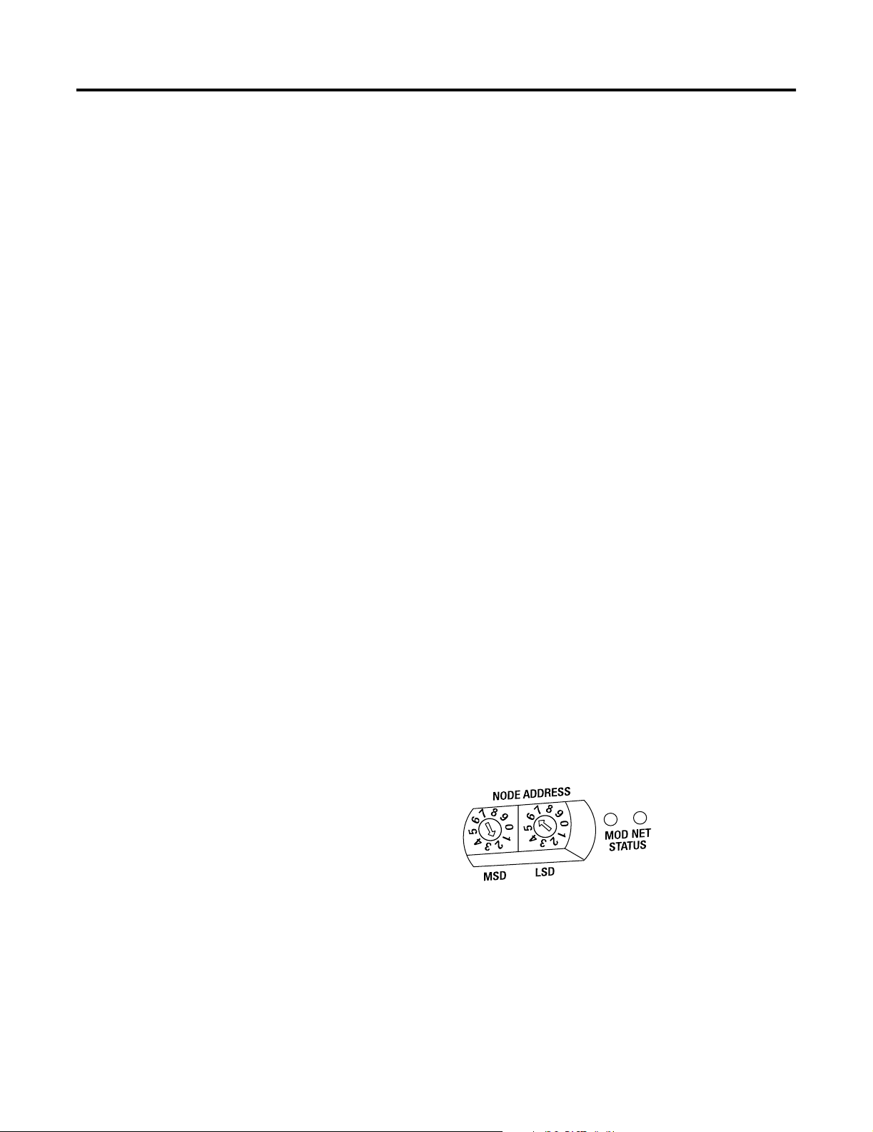
Set the Node Address on the DeviceNet 1790D-4T0/T4T0 Base
Block
Each base block comes with its internal program set for node address
63. To reset the node address, adjust the switches on the front of the
block. The two switches are most significant digit (MSD) and least
significant digit (LSD). The switches can be set between 00 and 63.
The rotary switches are read at block power up only. Switch settings
between 64 and 99 cause the block to use the last valid node address
stored internally.
Example: Node
Address is set at 26
The node address may also be set through RSNetWorx for DeviceNet
or a similar configuration tool. When software configuration is used
for the node address, the switches must be set between 64 and 99.
43230
Publication 1790-UM003A-EN-P - May 2002
Page 21
Installation and Wiring 2-7
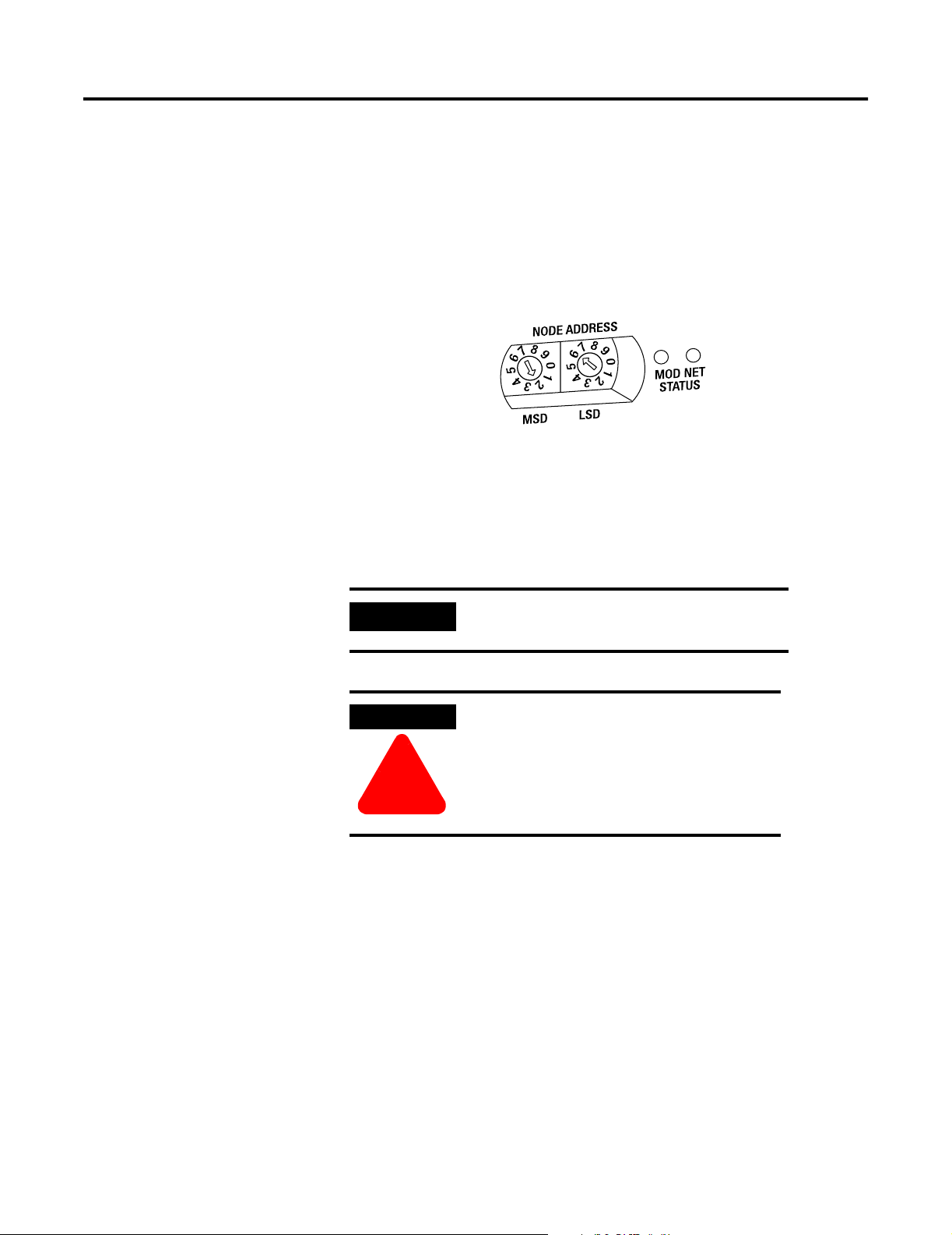
Set the Station Address on the 1790P-T4T0 PROFIBUS DP Base
Block
To set the station address, adjust the switches on the front of the base
block. The two switches are most significant digit (MSD) and least
significant digit (LSD). The switches can be set between 00 and 99.
Mounting
The rotary switches are read at base block power up only
Example: Node
Address is set at 26
43230
.
Mount the Base Block
You can mount the base block to a panel or DIN rail. We recommend
that you ground the panel or DIN rail before mounting the block.
IMPORTANT
WARNING
!
The RTD and thermocouple base modules
do not support any expansion blocks.
When used in a Class I, Division 2,
hazardous location, this equipment must
be mounted in a suitable enclosure with
proper wiring method that complies with
the governing electrical codes.
Panel Mounting
1. Place the block against the panel where you want to mount it.
2. Gently pull and position the expansion cover to the left.
3. Place a center punch, nail or similar device through the mounting
holes in the block and make two marks on the panel (lower left
and upper right corners of the module).
4. Remove the block and drill two holes in the panel to
accommodate each of the mounting screws.
Publication 1790-UM003A-EN-P - May 2002
Page 22
2-8 Installation and Wiring
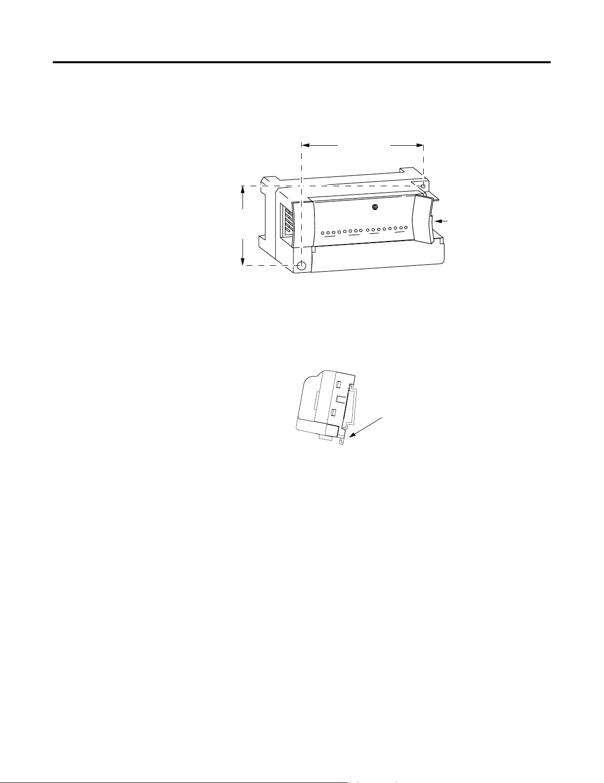
5. Replace the block on the panel and place a screw through each of
the two mounting holes. Tighten the screws until the block is
firmly in place
41 mm
1.6 in
.
95 mm
3.74 in
X
LD
ck
lo
CompactB
EXPANSION UNIT
0
0
7
1790-16BVOX
16 INPUTS-DCPOWER
7
Expansion
Cover
43242
DIN Rail Mounting
1. Hook the top slot of the block over the DIN Rail.
2. Pull down on the locking lever while pressing the block against
the rail
.
f
Locking Lever
43243
3. Push up on the locking lever to secure the block to the rail when
the block is flush against the rail.
Publication 1790-UM003A-EN-P - May 2002
Page 23
Installation and Wiring 2-9
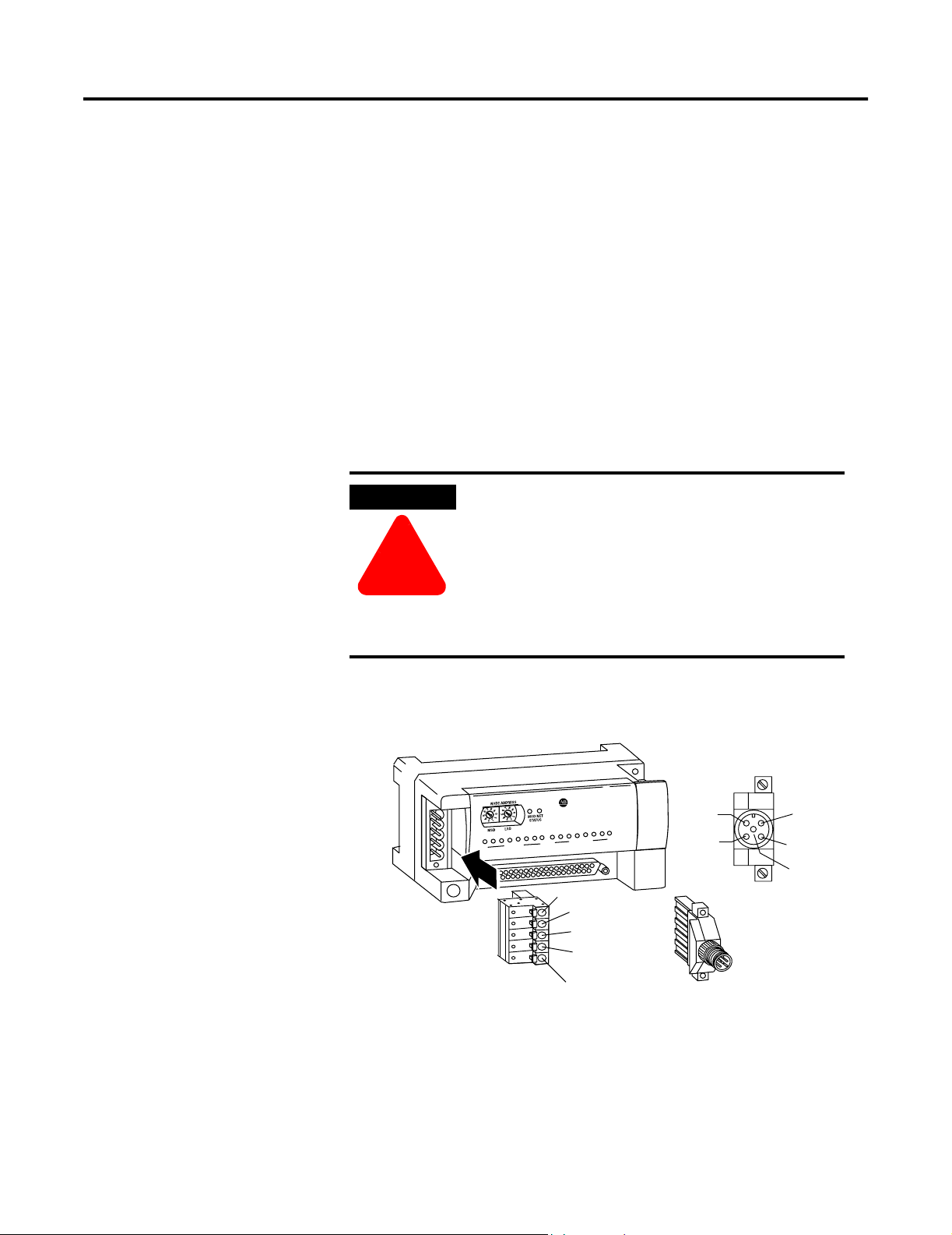
Connect the DeviceNet Cable to the 1790D-4T0/T4T0 Base Block
Follow these procedures when connecting the DeviceNet cable to the
base block.
The required DeviceNet connector is not supplied with the block you must purchase it separately. There are three types of connectors
that you can order directly from Rockwell Automation or your local
distributor:
• 1799-DNETCON - 5-position open style connector
• 1799-DNETSCON - 5-position open style connector with locking
screws
• 1799-DNC5MMS - 5-position open style to 5-pin micro male
connector with locking screws
WARNING
If you connect or disconnect the DeviceNet cable
with power applied to this module or any device
on the network, an electrical arc can occur. This
could cause an explosion in hazardous location
!
installations.
Be sure that power is removed or the area is
nonhazardous before proceeding.
Connect the DeviceNet wiring (drop line) to one of the DeviceNet
connectors as shown below. A color-coded wiring diagram is also
printed next to the connector on the left side of the module
Block LDX
Compact
Wiring Diagram for
1799-DNETCON
1790D-8BV8V
8 INPUTS/8OUTPUTS-DC POWER
0
0
7
7
V+ Red
Can_H White
Drain/Shield
Can_L Blue
V- Black
V+ Red
V- Black
Wiring Diagram for
1799-DNC5MMS
Drain/Shield
Can_H White
Can_L Blue
43245
Publication 1790-UM003A-EN-P - May 2002
Page 24
2-10 Installation and Wiring
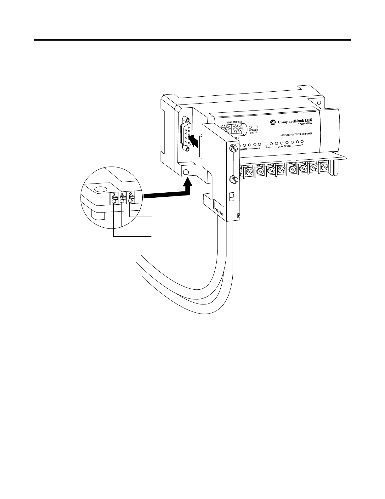
Connect the PROFIBUS DP Terminal Connector to the 1790P-T4T0
Base Block
Follow these procedures to connect the PROFIBUS DP terminal
connector to the base block.
WARNING
!
The required PROFIBUS female 9-pin D-sub connector is not
supplied with the base block - you must purchase it separately.
Before you connect female 9-pin D-sub connector to the base block,
make sure it is wired correctly as shown in the following table.
Table 2.3 Wiring Descriptions for 9-Pin D-Sub Connector
Pin Number Name Description
1 shield Shield, Protective Ground
2 M24V Minus 24V Output Voltage
3 RxD/TxD-P Receive/Transmit-Data-P
If you connect or disconnect the PROFIBUS cable
with power applied to this module or any device on
the network, an electrical arc can occur. This could
cause an explosion in hazardous location
installations.
Be sure that power is removed or the area is
nonhazardous before proceeding.
Publication 1790-UM003A-EN-P - May 2002
4 CNTR-P Control-p
5 DGND Data Ground
6 VP Voltage-Plus
7 P24V Plus 24V Output Voltage
8 RxD/TxD-N Receive/Transmit-Data-N
9 CNTR-N Control-N
Page 25
Module Power Connector
(underneath module)
Installation and Wiring 2-11
Once you have properly wired the connector, attach it to the base
block as shown below. Use the locking screws on the connector to
fasten it to the base block.
PROFIBUS Connector
Green - GND
Black - COM
Red - +24V dc
43249
Connect Power to the 1790P-T4T0 Block
To apply power to the block, refer to the above illustration.
Publication 1790-UM003A-EN-P - May 2002
Page 26

2-12 Installation and Wiring
Field Wiring Connections
System Wiring Guidelines
Consider the following when wiring your system:
General
• Route field wiring away from any other wiring and as far as
possible from sources of electrical noise, such as motors,
transformers, contactors, and ac devices. As a general rule, allow
at least 15.2 cm
(6 in.) of separation for every 120V of power.
• Routing field wiring in a grounded conduit can reduce electrical
noise.
• If field wiring must cross ac or power cables, ensure that they
cross at right angles.
• If multiple power supplies are used with analog millivolt inputs,
the power supply commons must be connected.
Terminal Block
• Do not use the module’s NC terminals as connection points.
• For millivolt sensors, use Belden 8761 shielded, twisted-pair wire
(or equivalent) to ensure proper operation and high immunity to
electrical noise.
• For a thermocouple, use the shielded, twisted-pair thermocouple
extension lead wires specified by the thermocouple manufacturer.
Using the incorrect type of thermocouple extension wire or not
following the correct polarity will cause invalid readings.
• To ensures optimum accuracy, limit overall cable impedance by
keeping a cable as short as possible. Locate the module as close to
input devices as the application permits.
Publication 1790-UM003A-EN-P - May 2002
Page 27
Grounding
Installation and Wiring 2-13
ATTENTION
!
• This product is intended to be mounted to a well-grounded
mounting surface such as a metal panel. Additional grounding
connections from the module’s mounting tabs or DIN rail (if used)
are not required unless the mounting surface cannot be grounded.
• Keep cable shield connections to ground as short as possible.
• Ground the shield drain wire at one end only. The typical location
is as follows.
– For grounded thermocouples or millivolt sensors, this is at the
sensor end.
– For insulated/ungrounded thermocouples, this is at the
module end. Contact your sensor manufacturer for additional
details.
The possibility exists that a grounded or exposed
thermocouple can become shorted to a potential
greater than that of the thermocouple itself. Due to
possible shock hazard, take care when wiring
grounded or exposed thermocouples. See Appendix
D, Using Thermocouple Junctions.
• If it is necessary to connect the shield drain wire at the module
end, connect it to earth ground using a panel or DIN rail mounting
screw.
• Refer to Industrial Automation Wiring and Grounding Guidelines,
Allen-Bradley publication 1770-4.1, for additional information.
Noise Prevention
• To limit the pickup of electrical noise, keep thermocouple and
millivolt signal wires as far as possible from power and load lines.
• If noise persists for a device, try grounding the opposite end of
the cable shield. (You can only ground one end at a time.)
Publication 1790-UM003A-EN-P - May 2002
Page 28
2-14 Installation and Wiring
Wiring the Module
ATTENTION
!
After the module is properly installed, follow the wiring procedure
below, using the proper thermocouple extension cable, or Belden
8761 for non-thermocouple applications.
signal wire
signal wire
To wire your module follow these steps.
1. At each end of the cable, strip some casing to expose the
individual wires.
2. Trim the signal wires to 2-inch (5 cm) lengths. Strip about 3/16
inch (5 mm) of insulation away to expose the end of the wire.
To prevent shock hazard, care should be taken when
wiring the module to analog signal sources. Before
wiring any module, disconnect power from the
system power supply and from any other source to
the module.
Cut foil shield
and drain wire
signal wire
drain wire
cable
foil shield
signal wire
ATTENTION
Be careful when stripping wires. Wire fragments
that fall into a module could cause damage at
power up.
!
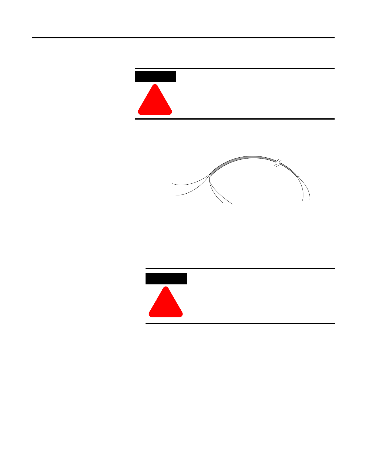
3. At one end of the cable, twist the drain wire and foil shield
together, bend them away from the cable, and apply shrink wrap.
Then earth ground at the preferred location based on the type of
sensor you are using. See Grounding on page 2-13.
Publication 1790-UM003A-EN-P - May 2002
Page 29
Installation and Wiring 2-15
4. At the other end of the cable, cut the drain wire and foil shield
back to the cable and apply shrink wrap.
5. Connect the signal wires to the terminal block. Connect the other
end of the cable to the analog input device.
6. Repeat steps 1 through 5 for each channel on the module.
TIP
See Appendix D Using Thermocouple Junctions for
additional information on wiring grounded,
ungrounded, and exposed thermocouple types.
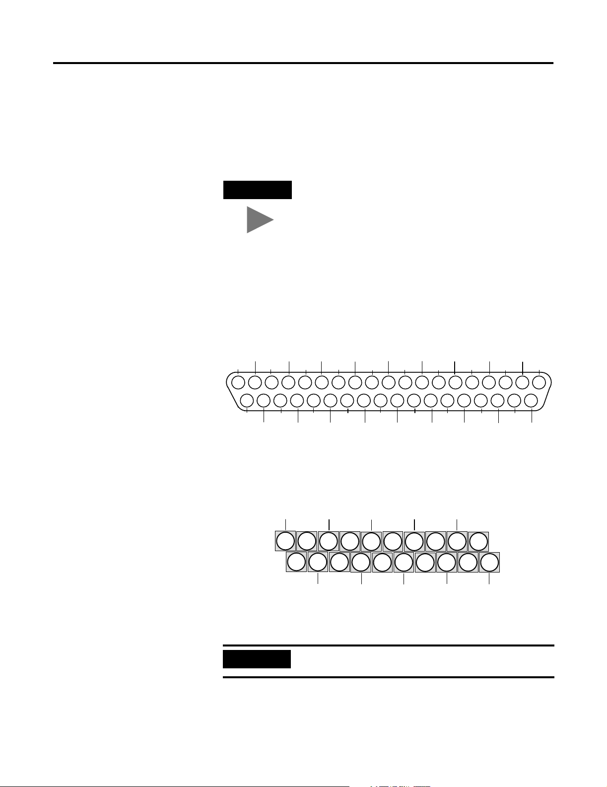
Wiring the Terminal Blocks
The following figures show how to wire the terminal blocks.
Figure 2.1 1790D-4R0-RTD Input Module D-Shell Wiring
+24V
19
GND
+24V
18
37
+24V
36
GND
17
35
GND
NC
16
34
NC
NC
15
33
NC
NC
14
CH0_B
CH0_A
13
32
NC
31
NC
CH1_A
12
30
NC
CH1_B
11
29
NC
10
28
NC
NC
9
27
NC
NC
CH2_A
8
26
NC
CH2_B
7
25
NC
CH3_A
6
24
NC
CH3-B
5
23
NC
4
22
NC
Wire pins 17, 18, 19 to Field Power (+) 24V dc
Wire pins 35, 36, 37 to Field Power (-) GND
Figure 2.2 1790D-T4R0 and 179P-T4R0 RTD Input Module D-Shell Wiring
+24V
Wire pin 1 to Field Power (+) 24V dc
Wire pin 2 to Field Power (-) GND
CH0_A
1
2
GND
CH1_A
3
4
CH1_B
CH0-B
CH2_A
NC
5
6
CH3_A
7
9
8
10
CH2_B
NC
NC
11
13
12
CH3_B
14
NC
NC
15
16
NC
NC
17
18
NC
NC
19
20
NC
432X1
NC
NC
NC
3
21
NC
1
2
20
NC
43256
IMPORTANT
When using an ungrounded thermocouple, the shield
must be connected to ground at the module end.
Publication 1790-UM003A-EN-P - May 2002
Page 30

2-16 Installation and Wiring
Cold Junction Compensation
Chapter Summary
To obtain accurate readings from each of the channels, the cold
junction temperature (temperature at the module’s terminal junction
between the thermocouple wire and the input channel) must be
compensated for. Cold junction compensating thermistors have been
integrated in the module.
In this chapter, you learned how to install and wire your modules. See
Chapter 3 to learn about module data, status, and channel
configuration with DeviceNet.
Publication 1790-UM003A-EN-P - May 2002
Page 31

Chapter
3
Module Data, Status, and Channel Configuration
for DeviceNet
After installation of the thermocouple/mV input module, you must
configure it for operation, usually using the programming software
compatible with the controller (for example, RSLogix 500™ or RSLogix
5000™) or scanner (RSNetWorx for DeviceNet). Once configuration is
complete and reflected in ladder logic, you will need to get the module
up and running and then verify its operation. This chapter includes
information on the following:
• module memory map
• accessing input image file data
• configuring channels
Module Memory Map
Input Image
File
• running the module
The module uses five input words for data and status bits (input image).
Figure 3.1 Memory Map
Word 0
Word 1
Word 2
Word 3
Word 4
43258
Input Image
5 words
Channel 0 Data Word
Channel 1 Data Word
Channel 2 Data Word
Channel 3 Data Word
Status Bits
Input Image
The input image file represents data words and status words. Input words
0 through 3 hold the input data that represents the value of the analog
inputs for channels 0 through 3. These data words are valid only when
the channel is enabled and there are no errors. Input word 4 holds status
bits.
Accessing Input Image File Data
1 Publication 1790-UM003A-EN-P
Five words of the processor input image table are reserved for the
module’s image data. You can access the information in the input image
file using the programming software configuration screen.
Page 32

3-2 Module Data, Status, and Channel Configuration for DeviceNet
Input Data File
The input data table lets you access thermocouple/mV input module read
data for use in the control program, via word and bit access. The data
table structure is shown in the tables below.
Table 3.1 Input Data Table
Word/
Bit
0 Thermocouple Input Data Channel 0
1 Thermocouple Input Data Channel 1
2 Thermocouple Input Data Channel 2
3 Thermocouple Input Data Channel 3
4 Not Used
Table 3.2 Input Data Table
Word Decimal Bit Description
Read Word 0 Bits 00-15 Channel 0 input data
Read Word 1 Bits 00-15 Channel 1 input data
Read Word 2 Bits 00-15 Channel 2 input data
Read Word 3 Bits 00-15 Channel 3 input data
1514131211109876543210
S11 S10 S9 S8 Not Used S3 S2 S1 S0
Read Word 4 Bits 00-03 Underrange for individual channels - Bit 00 corresponds to input
channel 0, bit 01 corresponds to input channel 1 and so on.
When set (1), the input signal is below the input channel’s
minimum range.
Bits 04-07 Not used: Set to 0
Bits 08-11 Overrange for individual channels - Bit 08 corresponds to input
channel 0, bit 09 corresponds to input channel 1 and so on.
When set (1), the input signal is above the input channel’s
maximum range, or open thermocouple is detected.
Bit 12-15 Not used: Set to 0.
Input Data Values
Data words 0 through 3 correspond to channels 0 through 3 and contain
the converted analog input data from the input device.
Under-Range Flag Bits (S0 to S3)
Under-range bits for channels 0 through 3 are contained in word 4, bits
0-3. When set (1), the under-range flag bit indicates a thermocouple
temperature that is less than the minimum allowed temperature. The
module automatically resets (0) the bit when the data value is again
within the normal operating range.
Publication 1790-UM003A-EN-P
Page 33

Module Data, Status, and Channel Configuration for DeviceNet 3-3
Over-Range Flag Bits (S8 to S11)
Over-range bits for channels 0 through 3 are contained in word 4, bits
8-11. When set (1), the over-range flag bit indicates a thermocouple
temperature that is greater than the maximum allowed temperature, a
resistance input that is greater than the maximum allowed resistance for
the module or an open channel is detected. The module automatically
resets (0) the bit when the data value is again within the normal operating
range.
Data Format
Thermocouple/mV data is presented in engineering units x1. The
engineering units data format represents real temperature or voltage data
provided by the module. Thermocouple data is reported in either °C
or °F.
Table 3.3 RTD Data Format
Data Format
Thermocouple
Input Type
B -300 to +1800°C -3000 to +18000 -5720 to +32720
E -270 to +1000°C -2700 to +10000 -4540 to +18320
J -210 to +1200°C -2100 to +12000 -3460 to +21920
K -270 to +1370°C -2700 to +13700 -4540 to +24980
R -50 to +1768°C -500 to +17680 -580 to +32140
S -50 to +1768°C -500 to +17680 -580 to +32140
T -270 to +400°C -2700 to +4000 -4540 to +7520
N -270 to +1300°C -2700 to +13000 -4540 to +23720
Table 3.4 Resistance Data Format
Range
Engineering Units x1
0.1°C0.1°F
Resistance Input Range
10uV -76.5 to +76.5mV -7650 to 7650
Data Format
Engineering Units x1
The module scales input data to the actual temperature values for the
selected thermocouple type per NIST ITS-90 standard. It expresses
temperatures in 0.1 degree units, either °C or °F, depending on which
temperature scale is selected. For mV inputs, the module expresses
voltage in 10uV units.
Negative temperatures are returned in 16-bit two’s complement binary
format. See Appendix B for a detailed explanation of two’s complement
binary numbers.
Publication 1790-UM003A-EN-P
Page 34

3-4 Module Data, Status, and Channel Configuration for DeviceNet
Filter Frequency
The module supports filter selections corresponding to filter frequencies
of 10 Hz, 25Hz, 50 Hz, 60 Hz, 100 Hz, 250 Hz, and 500 Hz. Your filter
frequency selection is determined by the desired range for the input type,
and the required effective resolution, which indicates the number of bits
in the input data that do not vary due to noise. Also consider the required
module update time when choosing a filter frequency. For example, the
10 Hz filter provides the greatest attenuation of 50 and 60 Hz noise and
the greatest resolution, but also provides the slowest response speed.
The choice that you make for filter frequency will affect:
• noise rejection characteristics for module input
• channel step response
• channel cutoff frequency
• effective resolution
• module update time
Effects of Filter Frequency on Noise Rejection
The filter frequency that you choose for the module determines the
amount of noise rejection for the inputs. A smaller filter frequency
(e.g. 10Hz) provides the best noise rejection and increases effective
resolution, but also increases channel update time. A larger filter
frequency (e.g. 500 Hz) provides lower noise rejection, but also decreases
the channel update time and effective resolution.
When selecting a filter frequency, be sure to consider channel cutoff
frequency and channel step response to obtain acceptable noise rejection.
Choose a filter frequency so that your fastest-changing signal is below that
of the filter’s cutoff frequency.
Common mode noise rejection for the module is better than 110 dB at 50
Hz (50 Hz filter) and 60 Hz (60 Hz filter). The module performs well in
the presence of common mode noise. Improper earth ground can be a
source of common mode noise.
IMPORTANT
Transducer power supply noise, transducer circuit noise,
and process variable irregularities can also be sources of
common mode noise.
Publication 1790-UM003A-EN-P
Page 35

Module Data, Status, and Channel Configuration for DeviceNet 3-5
Channel Step Response
Another module characteristic determined by filter frequency is channel
step response, as shown in the following table. The step response is the
time required for the analog input signal to reach 100 percent of its
expected final value, given a full-scale step change in the input signal.
Thus, if an input signal changes faster than the channel step response, a
portion of that signal will be attenuated by the channel filter. The channel
step response is calculated by a settling time of 3 x (1 / filter frequency).
Table 3.5 Filter Frequency vs. Channel Step Response
Filter Frequency Step Response
10 Hz 300 ms
25 Hz 120 ms
50 Hz 60 ms
60 Hz 50 ms
100 Hz 30 ms
250 Hz 12 ms
500 Hz 6 ms
Channel Cutoff Frequency
The channel cutoff frequency (-3 dB) is the point on the input channel
frequency response curve where frequency components of the input
signal are passed with 3 dB of attenuation. The following table shows
cutoff frequencies for the supported filters.
Table 3.6 Filter Frequency vs. Channel Cutoff Frequency
Filter Frequency Channel Cutoff Frequency
10 Hz 2.62 Hz
25 Hz 6.55 Hz
50 Hz 13.1 Hz
60 Hz 15.7 Hz
100 Hz 26.2 Hz
250 Hz 65.5 Hz
500 Hz 131 Hz
All frequency components at or below the cutoff frequency are passed by
the digital filter with less than 3 dB of attenuation. All frequency
components above the cutoff frequency are increasingly attenuated, as
shown in the following graphs for several of the input filter frequencies.
IMPORTANT
Channel cutoff frequency should not be confused with
channel update time. The cutoff frequency simply
determines how the digital filter attenuates frequency
components of the input signal.
Publication 1790-UM003A-EN-P
Page 36

3-6 Module Data, Status, and Channel Configuration for DeviceNet
Figure 3.2 Frequency Response Graphs
Gain (dB)
Gain (dB)
–20
–40
–60
–80
-100
-120
-140
-160
-180
- 200
- 200
0
–20
–40
–60
–80
-100
-120
-140
-160
-180
0
2.62 Hz
0
0
1 5 .72 Hz
10 Hz Input Filter Frequency
–3 dB
10
20
60 Hz Input Filter Frequency
–3 dB
60
120
30
40
Frequency (Hz)
180
Frequency (Hz)
240
0
–20
–40
–60
–80
-100
-120
Gain (dB)
-140
-160
-180
50
60
- 200
13. 1 Hz
–3 dB
0
50
100
150
200
250
300
Frequency (Hz)
250 Hz Input Filter Frequency
50 Hz Input Filter Frequency
300
360
0
–20
–40
–60
–80
-100
Gain (dB)
-120
-140
-160
-180
- 200
0
65 .5 Hz
–3 dB
900
Frequency (Hz)
1300
1150750500250
0
–20
–40
–60
–80
-100
-120
Gain (dB)
-140
-160
-180
- 200
131 Hz
–3 dB
Publication 1790-UM003A-EN-P
500 Hz Input Filter Frequency
2000
Frequency (Hz)
30000 250015001000500
43259
Page 37

Module Data, Status, and Channel Configuration for DeviceNet 3-7
Effective Resolution
The effective resolution for an input channel depends upon the filter
frequency selected for that channel. The table below identifies the
number of significant bits used to represent the data for the mV input
range for each available filter frequency. The number of significant bits is
defined as the number of bits that will have little or no jitter due to noise,
and is used in defining the effective resolution.
Table 3.7 Effective Resolution vs. Input FIlter Selection for mV Inputs
Filter Frequency Effective Resolution
10 Hz
25 Hz
50 Hz
60 Hz
100 Hz
250 Hz
500 Hz
sign +13 bits: 10
sign +13 bits: 10
sign +13 bits: 10
sign +13 bits: 10
sign +13 bits: 10
sign +12 bits: 20
sign +11 bits: 40
µV
µV
µV
µV
µV
µV
µV
The following graphs provide the effective resolution for each
thermocouple type for each available filter frequency. These graphs do
not include the affects of unfiltered input noise. Choose the frequency
that most closely matches your system requirements.
Figure 3.3 Type B Thermocouple
Publication 1790-UM003A-EN-P
Page 38

3-8 Module Data, Status, and Channel Configuration for DeviceNet
Figure 3.4 Type E Thermocouple
Figure 3.5 Type J Thermocouple
Publication 1790-UM003A-EN-P
Page 39

Module Data, Status, and Channel Configuration for DeviceNet 3-9
Figure 3.6 Type K Thermocouple
Figure 3.7 Type R Thermocouple
Publication 1790-UM003A-EN-P
Page 40

3-10 Module Data, Status, and Channel Configuration for DeviceNet
Figure 3.8 Type S Thermocouple
Figure 3.9 Type T Thermocouple
Publication 1790-UM003A-EN-P
Page 41

Module Data, Status, and Channel Configuration for DeviceNet 3-11
Figure 3.10 Type N Thermocouple
Cold Junction Compensation
When using thermocouples, cold junction compensation (CJC) is required
at the termination of the thermocouple wire. A cold junction can be
accomplished different ways:
• Use the built-in CJC
• Enter an estimated temperature
• Use an external CJC
Entering an estimated temperature may be the least accurate way for CJC
compensation. Using external CJC is the most expensive way. Using the
compensation built into the module provides the easiest way for CJC.
Built-in module cold junction linearization may be enabled or disabled. If
enabled, the proper cold junction compensation value will be applied to
the thermocouples. If disabled, the built-in cold junction temperature
data is not applied to the inputs. In this case, a cold junction value can be
added using the Cold Junction Offset parameter.
Publication 1790-UM003A-EN-P
Page 42
3-12 Module Data, Status, and Channel Configuration for DeviceNet
Determining Module Update Time
The module update time is defined as the time required for the module to
sample and convert the input signals. Module update time is dependent
on the number of input channels and the input filter selection.
The fastest update time occurs with the 500Hz filter enabled. The
following table shows update times for all filter frequencies.
Table 3.8 Module Update Time
Filter
Frequency
10 Hz 3.0 seconds
25 Hz 1.3 seconds
50 Hz 668 milliseconds
60 Hz 580 milliseconds
100 Hz 383 milliseconds
250 Hz 204 milliseconds
500 Hz 144 milliseconds
Module Update Time
Calculating Accuracy
Overall accuracy is determined from the combination of the module and
the thermocouple. The total error is the sum of the following:
• module accuracy and error due to temperature
• thermocouple error
• error due to thermocouple lead wire
• CJC error
Module and Temperature Error
The combined module error and error due to ambient temperature is
shown in the table below.
Table 3.9 Module and Temperature Error
Thermocouple Type Error (10Hz Filter) 0 to 55°C
B ±4.2°C
E ±2.5°C
J ±2.8°C
K ±3.3°C
R ±3.6°C
Publication 1790-UM003A-EN-P
S ±3.6°C
T ±1.3°C
N ±3.1°C
Page 43

Module Data, Status, and Channel Configuration for DeviceNet 3-13
Thermocouple Error
The table below summarizes thermocouple error (for more Thermocouple
Type information see Appendix C).
Table 3.10 Thermocouple Error
Thermocouple
Ty pe
B 870 to 1700 ±0.5% ±0.25%
E 0 to 900
J 0 to 750 ±2.2°C or ±0.75% ±1.1°C or ±0.4%
K 0 to 1250
R 0 to 1450 ±1.5°C or ±0.25% ±0.6°C or ±0.1%
S 0 to 1450 ±1.5°C or ±0.25% ±0.6°C or ±0.1%
T 0 to 350
N 0 to 1250 ±2.2°C or ±0.75% ±1.1°C or ±0.4%
* Whichever error factor is greater.
Useable Range °C Standard Tolerance
-200 to 0
-200 to 0
-200 to 0
*
Error
±1.7°C or ±0.5%
±1.7°C or ±1%
±2.2°C or ±0.75%
±2.2°C or ±2%
±1°C or ±0.75%
±1°C or ±1.5%
Special Tolerance
*
Error
±1°C or ±0.4%
±1°C or ±0.5%
±1.1°C or ±0.4%
NA
±0.5°C or ±0.4%
NA
Thermocouple Lead Wire Error
An error is introduced by the resistance of the thermocouple lead wire.
The lead wire resistance in combination with the module input
impedance acts as a voltage divider of the source thermoelectric voltage.
Use the following table to estimate this error.
Table 3.11 Thermocouple Lead Wire Error
Thermocouple Wire Resistance
(ohms per double foot resistance out and back per foot)
0.1 ohm insignificant
1 ohm insignificant
10 ohm 0.0004%
100 ohm 0.004%
1000 ohm 0.04%
10,000 ohm 0.4%
Error Impact
CJC Error
If the internal CJC compensation is turned off, an error factor is
introduced for either the external CJC or the estimated cold junction
value.
Publication 1790-UM003A-EN-P
Page 44

3-14 Module Data, Status, and Channel Configuration for DeviceNet
Total Error
As an example, a B Type thermocouple operating at 100°C with 1000
ohms of lead wire, internal CJC and 10Hz filter enabled, in an ambient
temperature of 30 to 50°C, is accurate to within:
Table 3.12 Example Error Calculation
Error Factor From Error
Module & Temperature Table 3.9 4.2°C
Thermocouple Table 3.10 .005 x 1000°C = 5.0°C
Lead Wire Table 3.11 .0004 x 1000°C = 0.4°C
TOTAL ERROR ±9.6°C
Configuring DeviceNet Thermocouple/mV Module (1790D-4T0/T4T0)
Configuring 1790D-4T0/T4T0 thermocouple/mV modules is as easy as
pointing and clicking. RSNetWorx™ lets you simply identify the network
and configure the I/O modules with easy-to-use Electronic Data Sheets
(EDS) files - just point to the field and click on your selection.
To obtain the EDS files you need to configure the modules, go to the
following Website: http:/www.ab.com/networks/eds.
EDS files for blocks with matching catalog numbers (for D-Shell and
terminal block versions) are the same. Thus, on the website or in
RSNetWorx for DeviceNet, there may be only one catalog number listed
for both versions.
When using 3rd party configuration software, simply load the EDS files
into the software and follow the vendor’s instructions.
The following example takes you through configuring your
thermocouple/mV module with RSNetWorx for DeviceNet, version 3.00 or
later.
Refer to Appendix C to configure the 1790P-T4T0 PROFIBUS module.
Publication 1790-UM003A-EN-P
Page 45

Module Data, Status, and Channel Configuration for DeviceNet 3-15
Configure DeviceNet Thermocouple/mV Modules Using RSNetWorx
Online Browse
Button
Following the steps below to configure 1790D-4T0/T4T0 thermocouple/
mV modules.
1. Open RSNetWorx for DeviceNet.
2. Using the selections on the left of the window below, construct you
system. (If your network is up, just click on the Online Browse
button.)
Publication 1790-UM003A-EN-P
Page 46

3-16 Module Data, Status, and Channel Configuration for DeviceNet
3. After setting up your system, double-click on the module you want to
configure. (If you are online, upload the configuration and existing
parameters from the module display.) A window similar to the
following appears.
Click the device
Parameters tab to
display the screen in
which you can set
parameters.
Thermocouple/mV modules will have parameters similar to the
following.
If you see a lock
next to an entry,
this indicates that
you cannot
change that
parameter.
On this screen, you see all the parameters for the module. These include Autobaud,
temperature units/filter frequency, cold junction compensation enable/manual
offset, module status and input thermocouple/mV type.
Publication 1790-UM003A-EN-P
Page 47

Module Data, Status, and Channel Configuration for DeviceNet 3-17
Module configuration parameters include Temperature Units/Notch
Filter frequency, Thermocouple/mV Input type, Cold Junction
Compensation Enable/Manual Offset Value and Autobaud.
Select the desired
temperature units (in
degrees C or F) and notch
filter frequency. ALL four
channels will be
configured identically.
Select the thermocouple/
mV input type for each
channel from the
dropdown list.
Select to have Autobaud
either Enabled or
Disabled.
Publication 1790-UM003A-EN-P
Page 48

3-18 Module Data, Status, and Channel Configuration for DeviceNet
Select to Enable or
Disable built-in cold
junction compensation.
If built-in CJC is
disabled, you can
enter a constant cold
junction offset value.
The value is always
entered in °C. The
range is 0 to 70°C
(000 to 700).
70°C is entered as 700
(158°F as 700 also).
Once module configuration is
complete, click either the
Download or Apply button
and click Ye s for the popup
question.
Publication 1790-UM003A-EN-P
Then click OK to close the
module properties window.
Page 49

Module Data, Status, and Channel Configuration for DeviceNet 3-19
n
Thermocouple/mV module parameters may be monitored real time.
The most convenient way to monitor module parameters is to:
a. Click the Groups checkbox.
b. Close the No Group Specified folder
c. Open the I/O Input Values and I/O Input Status folders.
d. Click the Monitor button.
The module parameters are sequentially updated.
Check Groups
Click the Monitor butto
Open these
folders
Chapter Summary
Close this folder
In this chapter, you learned how to setup and configure your module. See
Chapter 4 to learn how to troubleshoot using the module indicators.
Publication 1790-UM003A-EN-P
Page 50

3-20 Module Data, Status, and Channel Configuration for DeviceNet
Publication 1790-UM003A-EN-P
Page 51

Chapter
4
Diagnostics and Troubleshooting
This chapter describes module troubleshooting, containing information
on:
• safety considerations when troubleshooting
• module vs. channel operation
• the module’s diagnostic features
• critical vs. non-critical errors
• module condition data
• contacting Rockwell Automation for assistance
Safety Considerations
Safety considerations are an important element of proper troubleshooting
procedures. Actively thinking about the safety of yourself and others, as
well as the condition of your equipment, is of primary importance.
The following sections describe several safety concerns you should be
aware of when troubleshooting your control system.
ATTENTION
!
Never reach into a machine to actuate a switch because
unexpected motion can occur and cause injury.
Remove all electrical power at the main power disconnect
switches before checking electrical connections or inputs/
outputs causing machine motion.
Indicator Lights
When the green MOD and NET LED on the thermocouple module are
illuminated, it indicates that power is applied to the module, that it has
passed its internal tests and that the module is communicating on the
network.
Activating Devices When Troubleshooting
When troubleshooting, never reach into the machine to actuate a device.
Unexpected machine motion could occur.
1 Publication 1790-UM003A-EN-P
Page 52

4-2 Diagnostics and Troubleshooting
Stand Clear of the Equipment
When troubleshooting any system problem, have all personnel remain
clear of the equipment. The problem could be intermittent, and sudden
unexpected machine motion could occur. Have someone ready to operate
an emergency stop switch in case it becomes necessary to shut off power.
Program Alteration
There are several possible causes of alteration to the user program,
including extreme environmental conditions, Electromagnetic Interference
(EMI), improper grounding, improper wiring connections, and
unauthorized tampering. If you suspect a program has been altered,
check it against a previously saved master program.
Safety Circuits
Circuits installed on the machine for safety reasons, like over-travel limit
switches, stop push buttons, and interlocks, should always be hard-wired
to the master control relay. These devices must be wired in series so that
when any one device opens, the master control relay is de-energized,
thereby removing power to the machine. Never alter these circuits to
defeat their function. Serious injury or machine damage could result.
Module Operation vs. Channel Operation
The module performs diagnostic operations at both the module level and
the channel level. Module-level operations include functions such as
power-up, configuration, and communication with a controller.
Channel-level operations describe channel related functions, such as data
conversion and over- or under-range detection.
Internal diagnostics are performed at both levels of operation. When
detected, module error conditions are indicated by the module status LED.
Channel over-range or under-range conditions are reported in the
module’s input data table.
Publication 1790-UM003A-EN-P
Page 53

Diagnostics and Troubleshooting 4-3
Power-up Diagnostics
Power-up diagnostics includes module status and network status.
Module Status
At module power-up, a series of internal diagnostic tests are performed.
These diagnostic tests must be successfully completed. The following
table shows module status LED indictor operation.
Table 4.1
1790D-4T0/T4T0, 1790P-4T0
LED Indicator: Status: Description:
Module Status Solid Red Unrecoverable fault
Flashing Red Recoverable fault
Solid Green Normal operation - OK
Flashing Green Standby
Off No power
Network Status
The network status LED indicator shows the condition of the network
connection. The following tables show network status LED indicator
operation.
Table 4.2 1790D-4T0/T4T0 LED Descriptions
LED Indicator Status Description:
Network Status Solid Red Unrecoverable communication fault
Flashing Red Recoverable communication fault
Solid Green Communication path complete - OK
Flashing Green Communication path incomplete
Off Device not online or not powered
Table 4.3 1790P-4T0 LED Descriptions
LED Indicator Status Description
Network Status Solid Green Communication path complete - OK
Flashing Green Communication path incomplete
Off No power or baud rate search
Publication 1790-UM003A-EN-P
Page 54

4-4 Diagnostics and Troubleshooting
Channel Diagnostics
When an input channel is enabled, the module performs a diagnostic
check to see that the channel has been properly configured. In addition,
the channel is tested on every scan for configuration errors, over-range
and under-range, and open-circuit conditions.
Over- or Under-Range Detection
Whenever the data received at the channel word is out of the defined
operating range, an over-range or under-range error is indicated in input
data word 4.
Possible causes for an out-of-range condition include:
• The temperature is too hot or too cold for the type of thermocouple
being used.
• The wrong thermocouple is being used for the input type selected, or
for the configuration that you have programmed.
• The input device is faulty.
• The signal input from the input device is beyond the scaling range.
Open-Circuit Detection
On each scan, the module performs an open-circuit test on all channels.
Whenever an open-circuit condition occurs, the overrange bit for that
channel is set in input data word 4.
Possible causes of an open circuit include:
• the input device is broken
• a wire is loose or cut
• the input device is not installed on the configured channel
• a thermocouple is installed incorrectly
Publication 1790-UM003A-EN-P
Page 55

Diagnostics and Troubleshooting 4-5
Module Error Definition Table
Thermocouple/mV module errors are expressed on a channel basis in
input read word 4. The structure of the status data is shown in the
following table.
Table 4.4 Word Bit Position
Word Bit Description
1514131211109876543210
4 Not Used S11 S10 S9 S8 Not Used S3 S2 S1 S0
Table 4.5 Bit Descriptions
Word Decimal Bit Description
Bits 00-03 Underrange for individual channels. Bit 00 corresponds to input
channel 0, bit 01 corresponds to input channel 1 and so on.
When set (1), the input signal if below the input channel’s
minimum range
Channel LED Indicator Operation
Read Word 4
Bits 04-07 Not used: Set to 0
Bit 08-11 Overrange for individual channels. Bit 08 corresponds to input
channel 0, bit 09 corresponds to input channel 1 and so on.
When set (1), the input signal if above the input channel’s
maximum range, or open thermocouple is detected
Bit 12-15 Not used: Set to 0
Individual channel LED indicator operation is shown in the following
table.
Table 4.6 Individual Channel LEDs Indicator
I/O Channel LED Status Indicator
Status: Description
Flashing Green/Red Power up
Off Off line
Red On line and no field power
Red DeviceNet connection and no field power
Flashing Red Field power and open wire
Green Field power and valid input
Flashing Red Input over range, open input
Flashing Red Input under range
Flashing Red Recoverable fault
Publication 1790-UM003A-EN-P
Page 56

4-6 Diagnostics and Troubleshooting
Publication 1790-UM003A-EN-P
Page 57

Specifications
Appendix
A
Environmental Specifications
Environmental Specifications
Operating Temperature 0 to 55°C (32 to 131°F)
IEC 60068-2-1 (Test Ad, Operating Cold),
IEC 60068-2-2 (Test Bd, Operating Dry Heat),
IEC 60068-2-14 (Test Nb, Operating Thermal Shock)
Storage Temperature -40 to 85°C (-40 to 185°F)
IEC 60068-2-1 (Test Ab, Un-packaged Non-operating Cold),
IEC 60068-2-2 (Test Bb, Un-packaged Non-operating Dry Heat),
IEC 60068-2-14 (Test Na, Un-packaged Non-operating Thermal Shock)
Relative Humidity 5-90% non-condensing
IEC 60068-2-30 (Test Db, Un-packaged Non-operating)
Operating Altitude 2000m
Vibration I2g @ 10-500Hz
EC60068-2-6 (Test Fc, Operating)
Shock: Operating
Non-operating
Emissions Group 1, Class A
ESD Immunity 8kV air discharges
Radiated RF Immunity 10V/m with 1kHz sine-wave 80%AM from 80MHz to 1000MHz
EFT/B Immunity +
Surge Transient
Immunity
Conducted RF Immunity 10Vrms with 1kHz sine-wave 80%AM from 150kHzto 80MHz
Enclosure Type Rating None (open style)
Mounting DIN rail or screw
Dimensions 52 x 104 x 42mm (2.03 x 4.07 x 1.64in)
Weight 0.3lb (0.1kg)
I0g
30g
IEC60068-2-27 Test Ea, (Unpackaged Shock, ES#002)
CISPR 11
IEC 61000-4-2
10V/m with 200Hz 50% Pulse 100%AM @ 900Mhz
IEC 61000-4-3
1kV @ 5kHz on power ports
+2kV @ 5kHz on signal ports
2kV @ 5kHz on communications ports
+
IEC 61000-4-4
+
1kV line-line(DM) and +2kV line-earth(CM) on power ports
+
1kV line-line(DM) and +2kV line-earth(CM) on signal ports
2kV line-earth(CM) on shielded ports
+
IEC 61000-4-5
IEC 61000-4-6
1 Publication 1790-UM003A-EN-P
Page 58

A-2 Specifications
DeviceNet Specifications
PROFIBUS DP Specifications
Specification Value
Network protocol I/O Slave messaging:
- Poll command
- Bit Strobe command
- Cyclic command
- COS command
Network length 500 meters maximum @ 125Kbps
100 meters maximum @ 500Kbps
Indicators 1 red/green module status
1 red/green network status
Number of nodes 64 maximum - rotary switch type node address setting
Communication rate 125Kbps, 250Kbps, 500Kbps - auto baud rate selection
Isolation Type test 1250Vac rms for 60 seconds between field power and
DeviceNet (I/O to logic)
Wiring Refer to publication DN-6.7.2
PROFIBUS DP Specifications
Network Protocol PROFIBUS-DP (EN50170)
Communication of the slave with a Class 1 master
Communication of the slave with a Class 2 master
Redundancy Not supported
Repeater Control Signal RS485 signal
Implementation Type DPC31
Freeze Mode Supported
Sync Mode Supported
Auto Baud Rate Supported
Fail Safe Mode Supported
Station Type Slave
FMS Support Not supported
Indicators 1 red/green module status
1 red/green network status
Number of nodes 100 maximum - rotary switch type node address setting (0-99)
Network Length/
Communication rate
Isolation Type test 1250Vac rms for 60 seconds between field power and
9.6Kbps @ 1000m (3280ft)
19.2Kbps @ 1000m (3280ft)
45.45Kbps @ 1000m (3280 ft)
93.75Kbps @ 1000m (3280ft)
187.5Kbps @ 1000m (3280ft)
500Kbps @ 400m (1312ft)
1.5mbps @ 200m (656ft)
3mbps @ 100m (328ft)
6mbps @ 100m (328ft)
12mbps @ 100m (328ft)
PROFIBUS (I/O to logic)
Publication 1790-UM003A-EN-P
Page 59

Specifications A-3
General Specifications
General Specifications
Wiring Category
Product Certifications
(when product is marked)
1
2
c-UL-us UL Listed for Class I, Division 2 Group A,B,C,D Hazardous
Locations, certified for U.S. and Canada
UR UL Recognized Component Industrial Control Equipment
2
CE
European Union 89/336/EEC EMC Directive, compliant with:
EN 61000-6-4; Industrial Emissions
EN 50082-2; Industrial Immunity
EN61326; Meas./Control/Lab., Industrial Requirements
EN 61000-6-2; Industrial Immunity
2
C-Tick
Australian Radiocommunications Act, compliant with:
AS/NZS 2064; Industrial Emissions
ODVA ODVA conformance tested to ODVA DeviceNet
specifications
DeviceNet Power Supply voltage - 24V dc nominal
Voltage range - 11-28.8V dc
Power dissipation - 1.2W maximum @ 28.8V dc
PROFIBUS Power Supply voltage - 24V dc nominal
Voltage range - 19.2-28.8V dc
Power dissipation - 2W maximum @ 28.8V dc
Field Power Supply Voltage - 24Vdc nominal
Voltage Range - 21.6-26.4V dc (+
10%)
Power Dissipation - 1.5W maximum @ 26.4V dc
Isolation I/O to logic: photocoupler isolation
Isolation voltage: Type Test 1250V ac rms for 60 seconds
DeviceNet to logic: non-isolated
Field power: non-isolated
Indicators 4 red/green I/O status
Wiring
1790D-4R0
1790D-T4R0
1
Refer to publication 1770-4.1, Programmable Controller Wiring and Grounding Guidelines.
2 See the Product Certification link at www.ab.com for Declarations of Conformity, Certificates and other certification
details.
37-pin D-Shell connector
Terminal block connector screw torque: 7 inch pounds maximum
IMPORTANT These modules do not support any expansion modules.
Publication 1790-UM003A-EN-P
Page 60

A-4 Specifications
Thermocouple/mV Specifications
Thermocouple/mV Specifications
Inputs per module 4 channel, Thermocouple/mV Input
Input Range ±76.50 mV
Sensors Supported Sensor Type Degree Counts
Voltage 10
B 300 to 1800°C 3000 to 18000
E -270 to +1000°C -2700 to +10000
J -210 to +1200°C -2100 to +12000
K -270 to +1370°C -2700 to +13700
R -50 to +1768°C -500 to +17680
S -50 to +1768°C -500 to +17680
T -270 to +400°C -2700 to +4000
N -270 to 1300°C -2700 to 13000
Resolution 16 bits, 0.1°C/bit or 0.1°F/bit (Thermocouple Sensors)
20bit Sigma-Delta modulation converter
Data Format 16 bit Integer (2’s compliment)
Module Scan Time 140ms/channel @ Notch Filter = 60Hz
Overall accuracy 0.2% Full scale @ 0°C-55°C
Settable Notch Filter 10Hz (default), 25Hz, 50Hz, 60Hz, 100Hz, 250Hz, 500Hz
Open Wire Detection Out of range, open wiring
Cold Junction
Compensation Range
Input Impedance 5M ohm
0 to 70°C
-76.5 to +76.5 -7650 to +7650
µV
Publication 1790-UM003A-EN-P
Page 61

Appendix
B
Two’s Complement Binary Numbers
The processor memory stores 16-bit binary numbers. Two’s complement
binary is used when performing mathematical calculations internal to the
processor. Analog input values from the Thermocouple/mV module are
returned to the processor in 16-bit two’s complement binary format. For
positive numbers, the binary notation and two’s complement binary
notation are identical.
As indicated in the figure on the next page, each position in the number
has a decimal value, beginning at the right with 2
15
with 2
. Each position can be 0 or 1 in the processor memory. A 0
indicates a value of 0; a 1 indicates the decimal value of the position. The
equivalent decimal value of the binary number is the sum of the position
values.
0
and ending at the left
Positive Decimal Values
The far left position is always 0 for positive values. As indicated in the
figure below, this limits the maximum positive decimal value to 32767 (all
positions are 1 except the far left position). For example:
0000 1001 0000 1110 = 2
0010 0011 0010 1000 = 2
14
1 x 2 = 16384
13
1 x 2 = 8192
1 x 2 = 4096
0111111111111111
15
0 x 2 = 0
This position is always 0 for positive numbers.
11+28+23+22+21
13+29+28+25+23
12
11
1 x 2 = 2048
10
1 x 2 = 1024
9
1 x 2 = 512
1 x 2 = 256
= 2048+256+8+4+2 = 2318
= 8192+512+256+32+8 = 9000
8
7
1 x 2 = 128
6
1 x 2 = 64
1 x 2 = 32
5
4
1 x 2 = 16
3
1 x 2 = 8
1 x 2 = 4
2
1
1 x 2 = 2
0
1 x 2 = 1
43260
16384
8192
4096
2048
1024
512
256
128
64
32
16
8
4
2
1
32767
1 Publication 1790-UM003A-EN-P
Page 62

B-2 Two’s Complement Binary Numbers
Negative Decimal Values
In two’s complement notation, the far left position is always 1 for negative
values. The equivalent decimal value of the binary number is obtained by
subtracting the value of the far left position, 32768, from the sum of the
values of the other positions. In the figure below (all positions are 1), the
value is 32767 - 32768 = -1. For example:
1111 1000 0010 0011 = (2
14+213+212+211+25+21+20
) - 215 =
(16384+8192+4096+2048+32+2+1) - 32768 = 30755 - 32768 = -2013
14
1 x 2 = 16384
13
1 x 2 = 8192
12
1 x 2 = 4096
11
1 x 2 = 2048
10
1 x 2 = 1024
9
1 x 2 = 512
8
1 x 2 = 256
7
1 x 2 = 128
6
1 x 2 = 64
5
1 x 2 = 32
4
1 x 2 = 16
3
1 x 2 = 8
2
1 x 2 = 4
1 x 2 = 2
1111111111111111
15
1 x 2 = 32768
This position is always 1 for negative numbers.
1
0
1 x 2 = 1
16384
8192
4096
2048
1024
512
256
128
64
32
16
8
4
2
1
32767
43261
Publication 1790-UM003A-EN-P
Page 63

Appendix
C
Thermocouple Descriptions
The information in this appendix was extracted from the NIST Monograph
175 issued in January 1990, which supersedes the IPTS-68 Monograph 125
issued in March 1974. NIST Monograph 175 is provided by the United
States Department of Commerce, National Institute of Standards and
Technology.
International Temperature Scale of 1990
Type B Thermocouples
The ITS-90 [1,3] is realized, maintained, and disseminated by NIST to
provide a standard scale of temperature for use in science and industry in
the United States. This scale was adopted by the International Committee
of Weights and Measures (CIPM) at its meeting in September 1989, and it
became the official international temperature scale on January 1, 1990.
The ITS-90 supersedes the IPTS-68(75) [2] and the 1976 Provisional 0.5 K
to 30 K Temperature Scale (EPT-76) [4].
The adoption of the ITS-90 removed several deficiencies and limitations
associated with IPTS-68. Temperatures on the ITS-90 are in closer
agreement with thermodynamic values than were those of the IPTS-68
and EPT-76. Additionally, improvements have been made in the
non-uniqueness and reproducibility of the temperature scale, especially in
the temperature range from t68 = 630.74°C to 1064.43°C, where the type S
thermocouple was the standard interpolating device on the IPTS-68.
For additional technical information regarding ITS-90, refer to the NIST
Monograph 175.
This section discusses Platinum-30 percent Rhodium Alloy Versus
Platinum-6 percent Rhodium Alloy thermocouples, commonly called type
B thermocouples. This type is sometimes referred to by the nominal
chemical composition of its thermoelements: platinum - 30 percent
rhodium versus platinum - 6 percent rhodium or “30-6”. The positive (BP)
thermoelement typically contains 29.60 ± 0.2 percent rhodium and the
negative (BN) thermoelement usually contains 6.12 ± 0.02 percent
rhodium. The effect of differences in rhodium content are described later
in this section. An industrial consensus standard [21] (ASTM E1159-87)
specifies that rhodium having a purity of 99.98 percent shall be alloyed
with platinum of 99.99 percent purity to produce the thermoelements.
This consensus standard [21] describes the purity of commercial type B
materials that are used in many industrial thermometry applications that
meet the calibration tolerances described later in this section. Both
thermoelements will typically have significant impurities of elements such
as palladium, iridium, iron, and silicon [38].
1 Publication 1790-UM003A-EN-P
Page 64

C-2 Thermocouple Descriptions
Studies by Ehringer [39], Walker et al. [25,26], and Glawe and Szaniszlo
[24] have demonstrated that thermocouples, in which both legs are
platinum-rhodium alloys, are suitable for reliable temperature
measurements at high temperatures. Such thermocouples have been
shown to offer the following distinct advantages over types R and S
thermocouples at high temperatures: (1) improved stability, (2) increased
mechanical strength, and (3) higher operating temperatures.
The research by Burns and Gallagher [38] indicated that the 30-6
thermocouple can be used intermittently (for several hours) up to 1790°C
and continuously (for several hundred hours) at temperatures up to about
1700°C with only small changes in calibration. The maximum temperature
limit for the thermocouple is governed, primarily, by the melting point of
the Pt-6 percent rhodium thermoelement which is estimated to be about
1820°C by Acken [40]. The thermocouple is most reliable when used in a
clean oxidizing atmosphere (air) but also has been used successfully in
neutral atmospheres or vacuum by Walker et al [25,26], Hendricks and
McElroy [41], and Glawe and Szaniszlo [24]. The stability of the
thermocouple at high temperatures has been shown by Walker et al.
[25,26] to depend, primarily, on the quality of the materials used for
protecting and insulating the thermocouple. High purity alumina with low
iron-content appears to be the most suitable material for the purpose.
Type B thermocouples should not be used in reducing atmospheres, nor
those containing deleterious vapors or other contaminants that are
reactive with the platinum group metals [42], unless suitably protected
with nonmetallic protecting tubes. They should never be used in metallic
protecting tubes at high temperatures.
The Seebeck coefficient of type B thermocouples decreases with
decreasing temperature below about 1600°C and becomes almost
negligible at room temperature. Consequently, in most applications the
reference junction temperature of the thermocouple does not need to be
controlled or even known, as long as it between 0°C and 50°C. For
example, the voltage developed by the thermocouple, with the reference
junction at 0°C, undergoes a reversal in sign at about 42°C, and between
0°C and 50°C varies from a minimum of -2.6µV near 21°C to a maximum
of 2.3µV at 50°C. Therefore, in use, if the reference junction of the
thermocouple is within the range 0°C to 50°C, then a 0°C reference
junction temperature can be assumed and the error introduced will not
exceed 3µV. At temperatures above 1100°C, an additional measurement
error of 3µV (about 0.3°C) would be insignificant in most instances.
ASTM Standard E230-87 in the 1992 Annual Book of ASTM Standards [7]
specifies that the initial calibration tolerances for type B commercial
thermocouples be ±0.5 percent between 870°C and 1700°C. Type B
thermocouples can also be supplied to meet special tolerances of ±0.25
percent. Tolerances are not specified for type B thermocouples below
870°C.
Publication 1790-UM003A-EN-P
Page 65

Thermocouple Descriptions C-3
The suggested upper temperature limit of 1700°C given in the ASTM
standard [7] for protected type B thermocouples applies to AWG 24 (0.51
mm) wire. This temperature limit applies to thermocouples used in
conventional closed-end protecting tubes and it is intended only as a
rough guide to the user. It does not apply to thermocouples having
compacted mineral oxide insulation.
Type E Thermocouples
This section describes Nickel-Chromium Alloy Versus Copper-Nickel Alloy
thermocouples, known as type E thermocouples. This type, and the other
base-metal types, do not have specific chemical compositions given in
standards; rather, any materials whose emf-temperature relationship
agrees with that of the specified reference table within certain tolerances
can be considered to be a type E thermocouple. The positive
thermoelement, EP, is the same material as KP. The negative
thermoelement, EN, is the same material as TN.
The low-temperature research [8] by members of the NBS Cryogenics
Division showed that type E thermocouples are very useful down to
liquid hydrogen temperatures (n.b.p. about 20.3K) where their Seebeck
coefficient is about 8mV/°C. They may even be used down to liquid
helium temperatures (4.2°K) although their Seebeck coefficient becomes
quite low, only about 2mV/°C at 4K. Both thermoelements of type E
thermocouples have a relatively low thermal conductivity, good resistance
to corrosion in moist atmospheres, and reasonably good homogeneity.
For these three reasons and their relatively high Seebeck coefficients, type
E thermocouples have been recommended [8] as the most useful of the
letter-designated thermocouple types for low-temperature measurements.
For measurements below 20K, the non-letter-designated thermocouple,
KP versus gold-0.07, is recommended. The properties of this
thermocouple have been described by Sparks and Powell [12].
Type E thermocouples also have the largest Seebeck coefficient above
0°C for any of the letter-designated thermocouples. For that reason they
are being used more often whenever environmental conditions permit.
Type E thermocouples are recommended by the ASTM [5] for use in the
temperature range from -200°C to 900°C in oxidizing or inert
atmospheres. If used for extended times in air above 500°C, heavy gauge
wires are recommended because the oxidation rate is rapid at elevated
temperatures. About 50 years ago, Dahl [11] studied the thermoelectric
stability of EP and EN type alloys when heated in air at elevated
temperatures. His work should be consulted for details. More recent
stability data on these alloys in air were reported by Burley et al. [13].
Publication 1790-UM003A-EN-P
Page 66

C-4 Thermocouple Descriptions
Type E thermocouples should not be used at high temperatures in
sulfurous, reducing, or alternately reducing and oxidizing atmospheres
unless suitably protected with protecting tubes. They also should not be
used in vacuum (at high temperatures) for extended times because the
chromium in the positive thermoelement, a nickel-chromium alloy,
vaporizes out of solution and alters the calibration. In addition, their use
in atmospheres that promote “green-rot” corrosion of the positive
thermoelement should be avoided. Such corrosion results from the
preferential oxidation of chromium in atmospheres with low, but not
negligible, oxygen content and can lead to a large decrease in the
thermoelectric voltage of the thermocouple with time. The effect is most
serious at temperatures between 800°C and 1050°C.
The negative thermoelement, a copper-nickel alloy, is subject to
composition changes under thermal neutron irradiation since the copper
is converted to nickel and zinc.
Neither thermoelement of type E thermocouples is very sensitive to minor
changes in composition or impurity level because both are already heavily
alloyed. Similarly, they are also not extremely sensitive to minor
differences in heat treatment (provided that the treatment does not violate
any of the restrictions mentioned above). For most general applications,
they may be used with the heat treatment given by the wire
manufacturers. However, when the highest accuracy is sought, additional
preparatory heat treatments may be desirable in order to enhance their
performance. Details on this and other phases of the use and behavior of
type KP thermoelements (EP is the same as KP) are given in publications
by Pots and McElroy [14], by Burley and Ackland [15], by Burley [16], by
Wang and Starr [17,18], by Bentley [19], and by Kollie et al. [20].
Publication 1790-UM003A-EN-P
ASTM Standard E230-87 in the 1992 Annual Book of ASTM Standards [7]
specifies that the initial calibration tolerances for type E commercial
thermocouples be ±1.7°C or ±0.5 percent (whichever is greater) between
0°C and 900°C, and ±1.7°C or ±1 percent (whichever is greater) between
-200°C and 0°C. Type E thermocouples can also be supplied to meet
special tolerances which are equal to ±1°C or ±0.4 percent (whichever is
greater) between 0°C and 900°C, and ±1°C or ±0.5 percent (whichever is
greater) between -200°C and 0°C. Type E thermocouple materials are
normally supplied to meet the tolerances specified for temperatures above
0°C. The same materials, however, may not satisfy the tolerances specified
for the -200°C to 0°C range. If materials are required to meet the
tolerances below 0°C, this should be specified when they are purchased.
Page 67

Thermocouple Descriptions C-5
The suggested upper temperature limit, 870°C, given in the ASTM
standard [7] for protected type E thermocouples applies to AWG 8 (3.25
mm) wire. It decreases to 650°C for AWG 14 (1.63 mm), 540°C for AWG
20 (0.81 mm), 430°C for AWG 24 or 28 (0.51 mm or 0.33 mm), and 370°C
for AWG 30 (0.25 mm). These temperature limits apply to thermocouples
used in conventional closed-end protecting tubes and they are intended
only as a rough guide to the user. They do not apply to thermocouples
having compacted mineral oxide insulation.
Type J Thermocouples
This section discusses Iron Versus Copper-Nickel Alloy (SAMA)
thermocouples, called type J thermocouples. A type J thermocouple is
one of the most common types of industrial thermocouples, because of its
relatively high Seebeck coefficient and low cost. It has been reported that
more than 200 tons of type J materials are supplied annually to industry in
this country. However, this type is least suitable for accurate thermometry
because there are significant nonlinear deviations in the thermoelectric
output of thermocouples obtained from different manufacturers. These
irregular deviations lead to difficulties in obtaining accurate calibrations
based on a limited number of calibration points. The positive
thermoelement is commercially pure (99.5 percent Fe) iron, usually
containing significant impurity levels of carbon, chromium, copper,
manganese, nickel, phosphorus, silicon, and sulfur. Thermocouple wire
represents such a small fraction of the total production of commercial iron
wire that the producers do not control the chemical composition to
maintain constant thermoelectric properties. Instead, instrument
companies and thermocouple fabricators select material most suitable for
the thermocouple usage. The total and specific types of impurities that
occur in commercial iron change with time, location of primary ores, and
methods of smelting. Many unusual lots have been selected in the past,
for example spools of industrial iron wire and even scrapped rails from an
elevated train line. At present, iron wire that most closely fits these tables
has about 0.25 percent manganese and 0.12 percent copper, plus other
minor impurities.
The negative thermoelement for type J thermocouples is a copper-nickel
alloy known ambiguously as constantan. The word constantan has
commonly referred to copper-nickel alloys containing anywhere from 45
to 60 percent copper, plus minor impurities of carbon, cobalt, iron, and
manganese. Constantan for type J thermocouples usually contains about
55 percent copper, 45 percent nickel, and a small but thermoelectrically
significant amount of cobalt, iron, and manganese, about 0.1 percent or
more. It should be emphasized that type JN thermoelements are NOT
generally interchangeable with type TN (or EN) thermoelements, although
they are all referred to as “constantan”. In order to provide some
differentiation in nomenclature, type JN is often referred to as SAMA
constantan.
Publication 1790-UM003A-EN-P
Page 68

C-6 Thermocouple Descriptions
Type J thermocouples are recommended by the ASTM [5] for use in the
temperature range from 0°C to 760°C in vacuum, oxidizing, reducing, or
inert atmospheres. If used for extended times in air above 500°C, heavy
gauge wires are recommended because the oxidation rate is rapid at
elevated temperatures. Oxidation normally causes a gradual decrease in
the thermoelectric voltage of the thermocouple with time. Because iron
rusts in moist atmospheres and may become brittle, type J thermocouples
are not recommended for use below 0°C. In addition, they should not be
used unprotected in sulfurous atmospheres above 500°C.
The positive thermoelement, iron, is relatively insensitive to composition
changes under thermal neutron irradiation, but does exhibit a slight
increase in manganese content. The negative thermoelement, a
copper-nickel alloy, is subject to substantial composition changes under
thermal neutron irradiation since copper is converted to nickel and zinc.
Iron undergoes a magnetic transformation near 769°C and an
alpha-gamma crystal transformation near 910°C [6]. Both of these
transformations, especially the latter, seriously affect the thermoelectric
properties of iron, and therefore of type J thermocouples. This behavior
and the rapid oxidation rate of iron are the main reasons why iron versus
constantan thermocouples are not recommended as a standardized type
above 760°C. If type J thermocouples are taken to high temperatures,
especially above 900°C, they will lose the accuracy of their calibration
when they are recycled to lower temperatures. If type J thermocouples
are used in air at temperatures above 760°C, only the largest wire, AWG 8
(3.3 mm) should be used and they should be held at the measured
temperature for 10 to 20 minutes before readings are taken. The
thermoelectric voltage of the type J thermocouples may change by as
much as 40µV (or 0.6°C equivalent) per minute when first brought up to
temperatures near 900°C.
Publication 1790-UM003A-EN-P
ASTM Standard E230-87 in the 1992 Annual Book of ASTM Standards [7]
specifies that the initial calibration tolerances for type J commercial
thermocouples be ±2.2°C or ±0.75 percent (whichever is greater) between
0°C and 750°C. Type J thermocouples can also be supplied to meet
special tolerances, which are equal to approximately one-half the
standard tolerances given above. Tolerances are not specified for type J
thermocouples below 0°C or above 750°C.
The suggested upper temperature limit of 760°C given in the above ASTM
standard [7] for protected type J thermocouples applies to AWG 8 (3.25
mm) wire. For smaller diameter wires the suggested upper temperature
limit decreases to 590°C for AWG 14 (1.63 mm), 480°C for AWG 20 (0.81
mm), 370°C for AWG 24 or 28 (0.51 mm or 0.33 mm), and 320°C for AWG
30 (0.25 mm). These temperature limits apply to thermocouples used in
conventional closed-end protecting tubes and they are intended only as a
rough guide to the user. They do not apply to sheathed thermocouples
having compacted mineral oxide insulation.
Page 69

Thermocouple Descriptions C-7
Type K Thermocouples
This section describes Nickel-Chromium Alloy Versus Nickel-Aluminum
Alloy thermocouples, called type K thermocouples. This type is more
resistant to oxidation at elevated temperatures than types E, J, or T
thermocouples and, consequently, it finds wide application at
temperatures above 500°C. The positive thermoelement, KP, which is the
same as EP, is an alloy that typically contains about 89 to 90 percent
nickel, 9 to about 9.5 percent chromium, both silicon and iron in amounts
up to about 0.5 percent, plus smaller amounts of other constituents such
as carbon, manganese, cobalt, and niobium. The negative thermoelement,
KN, is typically composed of about 95 to 96 percent nickel, 1 to 1.5
percent silicon, 1 to 2.3 percent aluminum, 1.6 to 3.2 percent manganese,
up to about 0.5 percent cobalt and smaller amounts of other constituents
such as iron, copper, and lead. Also, type KN thermoelements with
modified compositions are available for use in special applications. These
include alloys in which the manganese and aluminum contents are
reduced or eliminated, while the silicon and cobalt contents are increased.
The low temperature research [8] by members of the NBS Cryogenics
Division showed that the type K thermocouple may be used down to
liquid helium temperatures (about 4K) but that its Seebeck coefficient
becomes quite small below 20K. Its Seebeck coefficient at 20K is only
about 4µV/K, being roughly one-half that of the type E thermocouple
which is the most suitable of the letter-designated thermocouples types
for measurements down to 20K. Type KP and type KN thermoelements
do have a relatively low thermal conductivity and good resistance to
corrosion in moist atmospheres at low temperatures. The thermoelectric
homogeneity of type KN thermoelements, however, was found [8] to be
not quite as good as that of type EN thermoelements.
Type K thermocouples are recommended by the ASTM [5] for use at
temperatures within the range -250°C to 1260°C in oxidizing or inert
atmospheres. Both the KP and the KN thermoelements are subject to
deterioration by oxidation when used in air above about 750°C, but even
so, type K thermocouples may be used at temperatures up to about
1350°C for short periods with only small changes in calibration. When
oxidation occurs it normally leads to a gradual increase in the
thermoelectric voltage with time. The magnitude of the change in the
thermoelectric voltage and the physical life of the thermocouple will
depend upon such factors as the temperature, the time at temperature, the
diameter of the thermoelements and the conditions of use.
Publication 1790-UM003A-EN-P
Page 70

C-8 Thermocouple Descriptions
The ASTM Manual [5] indicates that type K thermocouples should not be
used at high temperatures in sulfurous, reducing, or alternately oxidizing
and reducing atmospheres unless suitably protected with protecting tubes.
They also should not be used in vacuum (at high temperatures) for
extended times because the chromium in the positive thermoelement, a
nickel-chromium alloy, vaporizes out of solution and alters the calibration.
In addition, avoid their use in atmospheres that promote “green-rot”
corrosion [9] of the positive thermoelement. Such corrosion results from
the preferential oxidation of chromium in atmospheres with low, but not
negligible, oxygen content and can lead to a large decrease in the
thermoelectric voltage of the thermocouple with time. The effect is most
serious at temperatures between 800°C and 1050°C.
Both thermoelements of type K thermocouples are reasonably stable,
thermoelectrically, under neutron irradiation since the resulting changes
in their chemical compositions due to transmutation are small. The KN
thermoelements are somewhat less stable than the KP thermoelements in
that they experience a small increase in the iron content accompanied by
a slight decrease in the manganese and cobalt contents.
ASTM Standard E230-87 in the 1992 Annual Book of ASTM Standards [7]
specifies that the initial calibration tolerances for type K commercial
thermocouples be ±2.2°C or ±0.75 percent (whichever is greater) between
0°C and 1250°C, and ±2.2°C or ±2 percent (whichever is greater) between
-200°C and 0°C. In the 0°C to 1250°C range, type K thermocouples can be
supplied to meet special tolerances that are equal to approximately
one-half the standard tolerances given above. Type K thermocouple
materials are normally supplied to meet the tolerances specified for
temperatures above 0°C. However, the same materials may not satisfy
the tolerances specified for the -200°C to 0°C range. If materials are
required to meet the tolerances below 0°C, this should be specified when
they are purchased.
The suggested upper temperature limit of 1260°C given in the ASTM
standard [7] for protected type K thermocouples applies to AWG 8 (3.25
mm) wire. It decreases to 1090°C for AWG 14 (1.63 mm), 980°C for AWG
20 (0.81 mm), 870 for AWG 24 or 28 (0.51 mm or 0.33 mm), and 760°C for
AWG 30 (0.25 mm). These temperature limits apply to thermocouples
used in conventional closed-end protecting tubes and they are intended
only as a rough guide to the user. They do not apply to thermocouples
having compacted mineral oxide insulation.
Publication 1790-UM003A-EN-P
Page 71

Thermocouple Descriptions C-9
Type N Thermocouples
This section describes Nickel-Chromium-Silicon Alloy Versus
Nickel-Silicon-Magnesium Alloy thermocouples, commonly referred to as
type N thermocouples. This type is the newest of the letter-designated
thermocouples. It offers higher thermoelectric stability in air above 1000°C
and better air-oxidation resistance than types E, J, and K thermocouples.
The positive thermoelement, NP, is an alloy that typically contains about
84 percent nickel, 14 to 14.4 percent chromium, 1.3 to 1.6 percent silicon,
plus small amounts (usually not exceeding about 0.1 percent) of other
elements such as magnesium, iron, carbon, and cobalt. The negative
thermoelement, NN, is an alloy that typically contains about 95 percent
nickel, 4.2 to 4.6 percent silicon, 0.5 to 1.5 percent magnesium, plus
minor impurities of iron, cobalt, manganese and carbon totaling about 0.1
to 0.3 percent. The type NP and NN alloys were known originally [16] as
nicrosil and nisil, respectively.
The research reported in NBS Monograph 161 showed that the type N
thermocouple may be used down to liquid helium temperatures (about
4K) but that its Seebeck coefficient becomes very small below 20K. Its
Seebeck coefficient at 20K is about 2.5µV/K, roughly one-third that of
type E thermocouples which are the most suitable of the letter-designated
thermocouples types for measurements down to 20K. Nevertheless, types
NP and NN thermoelements do have a relatively low thermal conductivity
and good resistance to corrosion in moist atmospheres at low
temperatures.
Type N thermocouples are best suited for use in oxidizing or inert
atmospheres. Their suggested upper temperature limit, when used in
conventional closed-end protecting tubes, is set at 1260°C by the ASTM [7]
for 3.25 mm diameter thermoelements. Their maximum upper
temperature limit is defined by the melting temperature of the
thermoelements, which are nominally 1410°C for type NP and 1340°C for
type NN [5]. The thermoelectric stability and physical life of type N
thermocouples when used in air at elevated temperatures will depend
upon factors such as the temperature, the time at temperature, the
diameter of the thermoelements, and the conditions of use. Their
thermoelectric stability and oxidation resistance in air have been
investigated and compared with those of type K thermocouples by Burley
[16], by Burley and others [13,44-47], by Wang and Starr [17,43,48,49], by
McLaren and Murdock [33], by Bentley [19], and by Hess [50].
Publication 1790-UM003A-EN-P
Page 72

C-10 Thermocouple Descriptions
Type N thermocouples, in general, are subject to the same environmental
restrictions as types E and K. They are not recommended for use at high
temperatures in sulfurous, reducing, or alternately oxidizing and reducing
atmospheres unless suitably protected with protecting tubes. They also
should not be used in vacuum (at high temperatures) for extended times
because the chromium and silicon in the positive thermoelement, a
nickel-chromium-silicon alloy, vaporize out of solution and alter the
calibration. In addition, their use in atmospheres with low, but not
negligible, oxygen content is not recommended, since it can lead to
changes in calibration due to the preferential oxidation of chromium in
the positive thermoelement. Nevertheless, Wang and Starr [49] studied the
performances of type N thermocouples in reducing atmospheres, as well
as in stagnant air, at temperatures in the 870°C to 1180°C range and found
them to be markedly more stable thermoelectrically than type K
thermocouples under similar conditions.
The performance of type N thermocouples fabricated in metal-sheathed,
compacted ceramic insulated form also has been the subject of
considerable study. Anderson and others [51], Bentley and Morgan [52],
and Wang and Bediones [53] have evaluated the high-temperature,
thermoelectric stability of thermocouples insulated with magnesium oxide
and sheathed in Inconel and in stainless steel. Their studies showed that
the thermoelectric instabilities of such assemblies increase rapidly with
temperature above 1000°C. It was found also that the smaller the diameter
of the sheath the greater the instability. Additionally, thermocouples
sheathed in Inconel showed substantially less instability above 1000°C
than those sheathed in stainless steel. Bentley and Morgan [52] stressed
the importance of using Inconel sheathing with a very low manganese
content to achieve the most stable performance. The use of special Ni-Cr
based alloys for sheathing to improve the chemical and physical
compatibility with the thermoelements also has been investigated by
Burley [54-56] and by Bentley [57-60].
Publication 1790-UM003A-EN-P
Neither thermoelement of a type N thermocouple is extremely sensitive to
minor differences in heat treatment (provided that the treatment does not
violate any of the restrictions mentioned above). For most general
applications, they may be used with the heat treatment routinely given by
the wire manufacturer. Bentley [61,62], however, has reported reversible
changes in the Seebeck coefficient of type NP and NN thermoelements
when heated at temperatures between 200°C and 1000°C. These impose
limitations on the accuracy obtainable with type N thermocouples. The
magnitude of such changes was found to depend on the source of the
thermoelements. Consequently, when the highest accuracy and stability
are sought, selective testing of materials, as well as special preparatory
heat treatments beyond those given by the manufacturer, will usually be
necessary. Bentley’s articles [61,62] should be consulted for guidelines and
details.
Page 73

Thermocouple Descriptions C-11
ASTM Standard E230-87 in the 1992 Annual Book of ASTM Standards [7]
specifies that the initial calibration tolerances for type N commercial
thermocouples be ±2.2°C or ±0.75 percent (whichever is greater) between
0°C and 1250°C. Type N thermocouples can also be supplied to meet
special tolerances that are equal to approximately one-half the standard
tolerances given above. Tolerances are not specified for type N
thermocouples below 0°C.
The suggested upper temperature limit of 1260°C given in the ASTM
standard [7] for protected type N thermocouples applies to AWG 8 (3.25
mm) wire. It decreases to 1090°C for AWG 14 (1.63 mm), 980°C for AWG
20 (0.81 mm), 870°C for AWG 24 or 28 (0.51 mm or 0.33 mm), and 760°C
for AWG 30 (0.25 mm). These temperature limits apply to thermocouples
used in conventional closed-end protecting tubes and they are intended
only as a rough guide to the user. They do not apply to thermocouples
having compacted mineral oxide insulation.
Type R Thermocouples
This section describes Platinum-13 percent Rhodium Alloy Versus
Platinum thermocouples, called type R thermocouples. This type is often
referred to by the nominal chemical composition of its positive (RP)
thermoelement: platinum-13 percent rhodium. The negative (RN)
thermoelement is commercially-available platinum that has a nominal
purity of 99.99 percent [21]. An industrial consensus standard (ASTM
E1159-87) specifies that rhodium having a nominal purity of 99.98 percent
shall be alloyed with platinum of 99.99 percent purity to produce the
positive thermoelement, which typically contains 13.00 ± 0.05 percent
rhodium by weight. This consensus standard [21] describes the purity of
commercial type R materials that are used in many industrial thermometry
applications and that meet the calibration tolerances described later in this
section. It does not cover, however, the higher-purity, reference-grade
materials that traditionally were used to construct thermocouples used as
transfer standards and reference thermometers in various laboratory
applications and to develop reference functions and tables [22,23]. The
higher purity alloy material typically contains less than 500 atomic ppm of
impurities and the platinum less than 100 atomic ppm of impurities [22].
Differences between such high purity commercial material and the
platinum thermoelectric reference standard, Pt-67, are described in [22]
and [23].
A reference function for the type R thermocouple, based on the ITS-90
and the SI volt, was determined recently from new data obtained in a
collaborative effort by NIST and NPL. The results of this international
collaboration were reported by Burns et al [23]. The function was used to
compute the reference table given in this monograph.
Publication 1790-UM003A-EN-P
Page 74

C-12 Thermocouple Descriptions
Type R thermocouples have about a 12 percent larger Seebeck coefficient
than do Type S thermocouples over much of the range. Type R
thermocouples were not standard interpolating instruments on the
IPTS-68 for the 630.74°C to gold freezing-point range. Other than these
two points, and remarks regarding history and composition, all of the
precautions and restrictions on usage given in the section on type S
thermocouples also apply to type R thermocouples. Glawe and Szaniszlo
[24], and Walker et al [25,26] have determined the effects that prolonged
exposure at elevated temperatures (>1200°C) in vacuum, air, and argon
atmospheres have on the thermoelectric voltages of type R
thermocouples.
ASTM Standard E230-87 in the 1992 Annual Book of ASTM Standards [7]
specifies that the initial calibration tolerances for type R commercial
thermocouples be ±1.5°C or ±0.25 percent (whichever is greater) between
0°C and 1450°C. Type R thermocouples can be supplied to meet special
tolerances of ±0.6°C or ±0.1 percent (whichever is greater).
The suggested upper temperature limit, 1480°C, given in the ASTM
standard [7] for protected type R thermocouples applies to AWG 24 (0.51
mm) wire. This temperature limit applies to thermocouples used in
conventional closed-end protecting tubes and it is intended only as a
rough guide to the user. It does not apply to thermocouples having
compacted mineral oxide insulation.
Type S Thermocouples
This section describes Platinum-10 percent Rhodium Alloy Versus
Platinum thermocouples, commonly known as type S thermocouples.
This type is often referred to by the nominal chemical composition of its
positive (SP) thermoelement: platinum-10 percent rhodium. The negative
(SN) thermoelement is commercially available platinum that has a
nominal purity of 99.99 percent [21]. An industrial consensus standard
(ASTM E1159-87) specifies that rhodium having a nominal purity of 99.98
percent shall be alloyed with platinum of 99.99 percent purity to produce
the positive thermoelement, which typically contains 10.00 ± 0.05 percent
rhodium by weight. The consensus standard [21] describes the purity of
commercial type S materials that are used in many industrial thermometry
applications and that meet the calibration tolerances described later in this
section. It does not cover, however, the higher-purity, reference-grade
materials that traditionally were used to construct thermocouples used as
standard instruments of the IPTS-68, as transfer standards and reference
thermometers in various laboratory applications, and to develop reference
functions and tables [27,28]. The higher purity alloy material typically
contains less than 500 atomic ppm of impurities and the platinum less
than 100 atomic ppm of impurities [27]. Difference between such high
purity commercial material and the platinum thermoelectric reference
standard, Pt-67, are described in [27] and [28].
Publication 1790-UM003A-EN-P
Page 75

Thermocouple Descriptions C-13
A reference function for the type S thermocouple, based on the ITS-90
and the SI volt, was determined recently from new data obtained in an
international collaborative effort involving eight national laboratories. The
results of this international collaboration were reported by Burns et al.
[28]. The new function was used to compute the reference table given in
this monograph.
Research [27] demonstrated that type S thermocouples can be used from
-50°C to the platinum melting-point temperature. They may be used
intermittently at temperatures up to the platinum melting point and
continuously up to about 1300°C with only small changes in their
calibrations. The ultimate useful life of the thermocouples when used at
such elevated temperatures is governed primarily by physical problems of
impurity diffusion and grain growth, which lead to mechanical failure.
The thermocouple is most reliable when used in a clean oxidizing
atmosphere (air) but may be used also in inert gaseous atmospheres or in
a vacuum for short periods of time. However, type B thermocouples are
generally more suitable for such applications above 1200°C. Type S
thermocouples should not be used in reducing atmospheres, nor in those
containing metallic vapor (such as lead or zinc), nonmetallic vapors (such
as arsenic, phosphorus, or sulfur) or easily reduced oxides, unless they
are suitably protected with nonmetallic protecting tubes. Also, they should
never be inserted directly into a metallic protection tube for use at high
temperatures. The stability of type S thermocouples at high temperatures
(>1200°C) depends primarily upon the quality of the materials used for
protection and insulation, and has been studied by Walker et al. [25,26]
and by Bentley [29]. High purity alumina, with low iron content, appears
to be the most suitable material for insulating, protecting, and
mechanically supporting the thermocouple wires.
Both thermoelements of type S thermocouples are sensitive to impurity
contamination. In fact, type R thermocouples were developed essentially
because of iron contamination effects in some British platinum-10 percent
rhodium wires. The effects of various impurities on the thermoelectric
voltages of platinum based thermocouple materials have been described
by Rhys and Taimsalu [35], by Cochrane [36] and by Aliotta [37]. Impurity
contamination usually causes negative changes [25,26,29] in the
thermoelectric voltage of the thermocouple with time, the extent of which
will depend upon the type and amount of chemical contaminant. Such
changes were shown to be due mainly to the platinum thermoelement
[25,26,29]. Volatilization of the rhodium from the positive thermoelement
for the vapor transport of rhodium from the positive thermoelement to the
pure platinum negative thermoelement also will cause negative drifts in
the thermoelectric voltage. Bentley [29] demonstrated that the vapor
transport of rhodium can be virtually eliminated at 1700°C by using a
single length of twin-bore tubing to insulate the thermoelements and that
contamination of the thermocouple by impurities transferred from the
alumina insulator can be reduced by heat treating the insulator prior to its
use.
Publication 1790-UM003A-EN-P
Page 76

C-14 Thermocouple Descriptions
McLaren and Murdock [30-33] and Bentley and Jones [34] thoroughly
studied the performance of type S thermocouples in the range 0°C to
1100°C. They described how thermally reversible effects, such as
quenched-in point defects, mechanical stresses, and preferential oxidation
of rhodium in the type SP thermoelement, cause chemical and physical
inhomogeneities in the thermocouple and thereby limit its accuracy in this
range. They emphasized the important of annealing techniques.
The positive thermoelement is unstable in a thermal neutron flux because
the rhodium converts to palladium. The negative thermoelement is
relatively stable to neutron transmutation. Fast neutron bombardment,
however, will cause physical damage, which will change the
thermoelectric voltage unless it is annealed out.
At the gold freezing-point temperature, 1064.18°C, the thermoelectric
voltage of type S thermocouples increases by about 340uV (about 3
percent) per weight percent increase in rhodium content; the Seebeck
coefficient increases by about 4 percent per weight percent increase at the
same temperature.
Type T Thermocouples
ASTM Standard E230-87 in the 1992 Annual Book of ASTM Standards [7]
specifies that the initial calibration tolerances for type S commercial
thermocouples be ±1.5°C or ±0.25 percent (whichever is greater) between
0°C and 1450°C. Type S thermocouples can be supplied to meet special
tolerances of ±0.6°C or ±0.1 percent (whichever is greater).
The suggested upper temperature limit, 1480°C, given in the ASTM
standard [7] for protected type S thermocouples applies to AWG 24 (0.51
mm) wire. This temperature limit applies to thermocouples used in
conventional closed-end protecting tubes and it is intended only as a
rough guide to the user. It does not apply to thermocouples having
compacted mineral oxide insulation.
This section describes Copper Versus Copper-Nickel Alloy thermocouples,
called type T thermocouples. This type is one of the oldest and most
popular thermocouples for determining temperatures within the range
from about 370°C down to the triple point of neon (-248.5939°C). Its
positive thermoelement, TP, is typically copper of high electrical
conductivity and low oxygen content that conforms to ASTM Specification
B3 for soft or annealed bare copper wire. Such material is about 99.95
percent pure copper with an oxygen content varying from 0.02 to 0.07
percent (depending upon sulfur content) and with other impurities
totaling about 0.01 percent. Above about -200°C, the thermoelectric
properties of type TP thermoelements, which satisfy the above conditions,
are exceptionally uniform and exhibit little variation between lots. Below
about -200°C the thermoelectric properties are affected more strongly by
the presence of dilute transition metal solutes, particularly iron.
Publication 1790-UM003A-EN-P
Page 77

Thermocouple Descriptions C-15
The negative thermoelement, TN or EN, is a copper-nickel alloy known
ambiguously as constantan. The word constantan refers to a family of
copper-nickel alloys containing anywhere from 45 to 60 percent copper.
These alloys also typically contain small percentages of cobalt, manganese
and iron, as well as trace impurities of other elements such as carbon,
magnesium, silicon, etc. The constantan for type T thermocouples
usually contains about 55 percent copper, 45 percent nickel, and small but
thermoelectrically significant amounts, about 0.1 percent or larger, of
cobalt, iron, or manganese. It should be emphasized that type TN (or EN)
thermoelements are NOT generally interchangeable with type JN
thermoelements although they are all referred to as “constantan”. In order
to provide some differentiation in nomenclature, type TN (or EN) is often
referred to as Adams’ (or RP1080) constantan and type JN is usually
referred to as SAMA constantan.
The thermoelectric relations for type TN and type EN thermoelements are
the same, that is the voltage versus temperature equations and tables for
platinum versus type TN thermoelements apply to both types of
thermoelements over the temperature range recommended for each
thermocouple type. However, if should not be assumed that type TN and
type EN thermoelements may be used interchangeably or that they have
the same commercial initial calibration tolerances.
The low temperature research [8] by members of the NBS Cryogenics
Division showed that the type T thermocouple may be used down to
liquid helium temperatures (about 4K) but that its Seebeck coefficient
becomes quite small below 20K. Its Seebeck coefficient at 20K is only
about 5.6µV/K, being roughly two-thirds that of the type E thermocouple.
The thermoelectric homogeneity of most type TP and type TN (or EN)
thermoelements is reasonably good. There is considerable variability,
however, in the thermoelectric properties of type TP thermoelements
below about 70K caused by variations in the amounts and types of
impurities present in these nearly pure materials. The high thermal
conductivity of the type TP thermoelements can also be troublesome in
precise applications. For these reasons, type T thermocouples are
generally unsuitable for use below about 20K. Type E thermocouples are
recommended as the most suitable of the letter-designated thermocouple
types for general low-temperature use, since they offer the best overall
combination of desirable properties.
Publication 1790-UM003A-EN-P
Page 78

C-16 Thermocouple Descriptions
Type T thermocouples are recommended by the ASTM [5] for use in the
temperature range from -200°C to 370°C in vacuum or in oxidizing,
reducing or inert atmospheres. The suggested upper temperature limit for
continuous service of protected type T thermocouples is set at 370°C for
AWG 14 (1.63 mm) thermoelements since type TP thermoelements
oxidize rapidly above this temperature. However, the thermoelectric
properties of type TP thermoelements are apparently not grossly affected
by oxidation since negligible changes in the thermoelectric voltage were
observed at NBS [10] for AWG 12, 18, and 22 type TP thermoelements
during 30 hours of heating in air at 500°C. At this temperature the type TN
thermoelements have good resistance to oxidation and exhibit only small
voltage changes heated in air for long periods of time, as shown by the
studies of Dahl [11]. Higher operating temperatures, up to at least 800°C,
are possible in inert atmospheres where the deterioration of the type TP
thermoelement is no longer a problem. The use of type T thermocouples
in hydrogen atmospheres at temperatures above about 370°C is not
recommended since type TP thermoelements may become brittle.
Type T thermocouples are not well suited for use in nuclear environments
since both thermoelements are subject to significant changes in
composition under thermal neutron irradiation. The copper in the
thermoelements is converted to nickel and zinc.
Because of the high thermal conductivity of type TP thermoelements,
special care should be exercised when using the thermocouples to ensure
that the measuring and reference junctions assume the desired
temperatures.
ASTM Standard E230-87 in the 1992 Annual Book of ASTM Standards [7]
specifies that the initial calibration tolerances for type T commercial
thermocouples be ±1°C or ±0.75 percent (whichever is greater) between
0°C and 350°C, and ±1°C or ±1.5 percent (whichever is greater) between
-200°C and 0°C. Type T thermocouples can also be supplied to meet
special tolerances which are equal to approximately one-half the standard
tolerances given above.
Type T thermocouple materials are normally supplied to meet the
tolerances specified for temperatures above 0°C. However, the same
materials may not satisfy the tolerances specified for the -200°C to 0°C
range. If materials are required to meet the tolerances below 0°C, this
should be specified when they are purchased.
The suggested upper temperature limit of 370°C given in the ASTM
standard [7] for protected type T thermocouples applies to AWG 14 (1.63
mm) wire. It decreases to 260°C for AWG 20 (0.81 mm), 200°C for AWG
24 or 28 (0.51 mm or 0.33 mm), and 150°C for AWG 30 (0.25 mm). These
temperature limits apply to thermocouples used in conventional
closed-end protecting tubes and they are intended only as a rough guide
to the user. They do not apply to thermocouples having compacted
mineral oxide insulation.
Publication 1790-UM003A-EN-P
Page 79

Thermocouple Descriptions C-17
References
[1] Preston-Thomas, H. The International Temperature Scale of 1990
(ITS-90). Metrologia 27, 3-10; 1990. ibid. p. 107.
[2] The International Practical Temperature Scale of 1968, Amended
Edition of 1975. Metrologia 12, 7-17, 1976.
[3] Mangum, B. W.; Furukawa, G. T. Guidelines for realizing the
International Temperature Scale of 1990 (ITS-90). Natl. Inst. Stand.
Technol. Tech. Note 1265; 1990 August. 190 p.
[4] The 1976 Provisional 0.5 to 30 K Temperature Scale. Metrologia 15,
65-68; 1979.
[5] ASTM, American Society for Testing and Materials. Manual on the use
of thermocouples in temperature measurement. Special Tech. Publ. 470B;
edited by Benedict, R. P.; Philadelphia: ASTM; 1981. 258p.
[6] Hansen, M.; Anderko, K. Constitution of binary alloys. New York:
McGraw-Hill Book Co.; 1958.
[7] ASTM, American Society for Testing and Materials, Standard E230-87,
1992 Annual Book of ASTM Standards. Vol. 14.03; Philadelphia: ASTM;
1992. 102-230.
[8] Sparks, L. L.; Powell, R. L.; Hall, W. J. Reference tables for
low-temperature thermocouples. Natl. Bur. Stand. (U.S.) Monogr. 124;
1972 June. 61p.
[9] Starr, C.D.; Wang, T. P. Effect of oxidation on stability of
thermocouples, Proceedings of the American Society for Testing and
Materials Vol. 63, 1185-1194; 1963.
[10] Roeser, W. F.; Dahl, A. I. Reference tables for iron-constantan and
copper-constantan thermocouples. J. Res. Natl. Bur. Stand. (U.S.) 20,
337-355; RP1080; 1938 March.
[11] Dahl, A. I. Stability of base-metal thermocouples in air from 800 to
2200°F. J. Res. Natl. Bur. Stand. (U.S.) 24, 205-224; RP1278; 1940
February.
[12] Sparks, L. L.; Powell, R. L. Low temperatures thermocouples: KP,
“normal” silver, and copper versus Au-0.02 at % Fe and Au-0.07 at % Fe.
J. Res. Natl. Bur. Stand. (U.S.) 76A(3), 263-283; 1972 May-June.
[13] Burley, N. A.; Hess, R. M.; Howie, C. F.; Coleman, J. A. The nicrosil
versus nisil thermocouple: A critical comparison with the ANSI standard
letter-designated base-metal thermocouples. Temperature: Its
Measurement and Control in Science and Industry; Vol. 5, Schooley, J. F.,
ed.; New York: American Institute of Physics; 1982. 1159-1166.
Publication 1790-UM003A-EN-P
Page 80

C-18 Thermocouple Descriptions
[14] Potts, J. F. Jr.; McElroy, D. L. The effects of cold working, heat
treatment, and oxidation on the thermal emf of nickel-base
thermoelements. Herzfeld, C. M.; Brickwedde, F. G.; Dahl, A. I.; Hardy, J.
D., ed. Temperature: Its Measurement and Control in Science and
Industry; Vol. 3, Part 2; New York: Reinhold Publishing Corp.; 1962.
243-264.
[15] Burley, N. A.; Ackland, R. G. The stability of the thermo-emf/
temperature characteristics of nickel-base thermocouples. Jour. of
Australian Inst. of Metals 12(1), 23-31; 1967.
[16] Burley, N. A. Nicrosil and nisil: Highly stable nickel-base alloys for
thermocouples. Temperature: Its Measurement and Control in Science
and Industry; Vol. 4, Plumb, H. H., ed.; Pittsburgh: Instrument Society of
America; 1972. 1677-1695.
[17] Wang, T. P.; Starr, C. D. Electromotive force stability of nicrosil-nisil.
Journal of Testing and Evaluation 8(4), 192-198; 1980.
[18] Starr, C. D.; Wang, T. P. Effect of oxidation on stability of
thermocouples, Proceedings of the American Society for Testing and
Materials Vol. 63 1185-1194; 1963.
[19] Bentley, R. E. Short-term instabilities in thermocouples containing
nickel-based alloys. High Temperatures- High Pressures 15, 599-611; 1983.
[20] Kollie, T. G.; Horton, J. L.; Carr, K. R.; Herskovitz, M. B.; Mossman, C.
A. Temperature measurement errors with type K (Chromel vs. Alumel)
thermocouples due to short-ranged ordering in Chromel. Rev. Sci.
Instrum. 46, 1447-1461; 1975.
[21] ASTM, American Society for Testing and Materials, Standard E1159-87,
1992 Annual Book of ASTM Standards. Vol. 14.03; Philadelphia: ASTM;
1992. 388-389.
[22] Bedford, R. E.; Ma, C. K.; Barber, C. R.; Chandler, T. R.; Quinn, T. J.;
Burns, G. W.; Scroger, M. New reference tables for platinum 10%
rhodium/platinum and platinum 13% rhodium/platinum thermocouples.
Temperature: Its Measurement and Control in Science and Industry; Vol.
4, Part 3, p. 1585; Plumb, H. H., ed.; Pittsburgh: Instrument Society of
America; 1972.
Publication 1790-UM003A-EN-P
[23] Burns, G. W.; Strouse, G. F.; Mangum, B. W.; Croarkin, M. C.;
Guthrie, W. F.; Chattle, M. New reference functions for platinum-13%
rhodium versus platinum (type R) and platinum-30% rhodium versus
platinum-6% rhodium (type B) thermocouples based on the ITS-90. in
Temperature: Its Measurement and Control in Science and Industry; Vol.
6; Schooley, J. F., ed.; New York: American Institute of Physics; 1992.
559-564.
Page 81

Thermocouple Descriptions C-19
[24] Glawe, G. E.; Szaniszlo, A. J. Long-term drift of some noble- and
refractory-metal thermocouples at 1600K in air, argon, and vacuum.
Temperature: Its Measurement and Control in Science and Industry; Vol.
4; Plumb, H. H., ed.; Pittsburgh: Instrument Society of America; 1972.
1645-1662.
[25] Walker, B. E.; Ewing, C. T.; Miller, R. R. Thermoelectric instability of
some noble metal thermocouples at high temperatures. Rev. Sci. Instrum.
33, 1029-1040; 1962.
[26] Walker, B. E.; Ewing, C. T.; Miller, R. R. Study of the instability of
noble metal thermocouples in vacuum. Rev. Sci. Instrum. 36, 601-606;
1965.
[27] Bedford, R. E.; Ma, C. K.; Barber, C. R.; Chandler, T. R.; Quinn, T. J.;
Burns, G. W.; Scroger, M. New reference tables for platinum 10%
rhodium/platinum and platinum 13% rhodium/platinum thermocouples.
Temperature: Its Measurement and Control in Science and Industry; Vol.
4; Plumb, H. H., ed.; Pittsburgh: Instrument Society of America; 1972.
1585-1603.
[28] Burns, G. W.; Strouse, G. F.; Mangum, B. W.; Croarkin, M. C.;
Guthrie, W. F.; Marcarino, P.; Battuello, M.; Lee, H. K.; Kim, J. C.; Gam, K.
S.; Rhee, C.; Chattle, M.; Arai, M.; Sakurai, H.; Pokhodun, A. I.; Moiseeva,
N. P.; Perevalova, S. A.; de Groot, M. J.; Zhang, J.; Fan, K.; Wu, S. New
reference functions for platinum-10% rhodium versus platinum (type S)
thermocouples based on the ITS-90, Part I and Part II. in Temperature:
Its Measurement and Control in Science and Industry; Vol. 6; Schooley, J.
F., ed.; New York: American Institute of Physics; 1992. 537-546.
[29] Bentley, R. E. Changes in Seebeck coefficient of Pt and Pt 10% Rh
after use to 1700C in high-purity polycrystalline alumina. Int. J.
Thermophys. 6(1), 83-99; 1985.
[30] McLaren, E. H.; Murdock, E. G. New considerations on the
preparation, properties and limitations of the standard thermocouple for
thermometry. Temperature: Its Measurement and Control in Science and
Industry; Vol. 4; Plumb, H. H., ed.; Pittsburgh: Instrument Society of
America; 1972. 1543-1560.
[31] McLaren, E. H.; Murdock, E. G. The properties of Pt/PtRh
thermocouples for thermometry in the range 0-1100°C: I. Basic
measurements with standard thermocouples. National Research Council
of Canada Publication APH 2212/NRCC 17407; 1979.
[32] McLaren, E. H.; Murdock, E. G. The properties of Pt/PtRh
thermocouples for thermometry in the range 0-1100°C: II. Effect of heat
treatment on standard thermocouples. National Research Council of
Canada Publication APH 2213/NRCC 17408; 1979.
Publication 1790-UM003A-EN-P
Page 82

C-20 Thermocouple Descriptions
[33] McLaren, E. H.; Murdock, E. G. Properties of some noble and base
metal thermocouples at fixed points in the range 0-1100°C. Temperature:
Its Measurement and Control in Science and Industry; Vol. 5; Schooley, J.
F., ed.; New York: American Institute of Physics; 1982. 953-975.
[34] Bentley, R. E.; Jones, T. P. Inhomogeneities in type S thermocouples
when used to 1064°C. High Temperatures- High Pressures 12, 33-45;
1980.
[35] Rhys, D. W.; Taimsalu, P. Effect of alloying additions on the
thermoelectric properties of platinum. Engelhard Tech. Bull. 10, 41-47;
1969.
[36] Cochrane, J. Relationship of chemical composition to the electrical
properties of platinum. Engelhard Tech. Bull. 11, 58-71; 1969. Also in
Temperature: Its Measurement and Control in Science and Industry; Vol.
4; Plumb, H. H., ed.; Pittsburgh: Instrument Society of America; 1972.
1619-1632.
[37] Aliotta, J. Effects of impurities on the thermoelectric properties of
platinum. Inst. and Control Systems, 106-107; March 1972.
[38] Burns, G. W.; Gallagher, J. S. Reference tables for the Pt-30 percent
Rh versus Pt-6 percent Rh thermocouple. J. Res. Natl. Bur. Stand. (U.S.)
70C, 89-125; 1966.
[39] Ehringer, H. Uber die lebensdauer von PtRh-thermoelementen.
Metall 8, 596-598; 1954.
[40] Acken, J. S. Some properties of platinum-rhodium alloys. J. Res.
Natl. Bur. Stand. (U.S.) 12, 249; RP650; 1934.
[41] Hendricks, J. W.; McElroy, D. L. High temperature- high vacuum
thermocouple drift tests. Environmental Quarterly, 34-38; March 1967.
[42] Zysk, E. D. Platinum metal thermocouples. Temperature: Its
Measurement and Control in Science and Industry; Vol. 3; Herzfeld, C.
M., ed.; New York: Reinhold Publishing Corp.; 1962. Part 2, pp. 135-156.
[43] Starr, C. D.; Wang, T. P. A new stable nickel-base thermocouple.
Journal of Testing and Evaluation 4(1), 42-56; 1976.
Publication 1790-UM003A-EN-P
[44] Burley, N. A.; Powell, R. L.; Burns, G. W.; Scroger, M. G. The nicrosil
versus nisil thermocouple: properties and thermoelectric reference data.
Natl. Bur. Stand. (U.S.) Monogr. 161; 1978 April. 167p.
[45] Burley, N. A.; Jones, T. P. Practical performance of nicrosil-nisil
thermocouples. Temperature Measurement, 1975; Billing, B. F.; Quinn,
T. J., ed.; London and Bristol: Institute of Physics; 1975. 172-180.
Page 83

Thermocouple Descriptions C-21
[46] Burley, N. A.; Hess, R. M.; Howie, C. F. Nicrosil and nisil: new
nickel-based thermocouple alloys of ultra-high thermoelectric stability.
High Temperatures- High Pressures 12, 403-410; 1980.
[47] Burley, N. A.; Cocking, J. L.; Burns, G. W.; Scroger, M. G. The
nicrosil versus nisil thermocouple: the influence of magnesium on the
thermoelectric stability and oxidation resistance of the alloys.
Temperature: Its Measurement and Control in Science and Industry; Vol.
5, Schooley, J. F., ed.; New York: American Institute of Physics; 1982.
1129-1145.
[48] Wang, T. P.; Starr, C. D. Nicrosil-nisil thermocouples in production
furnaces in the 538°C (1000°F) to 1177°C (2150°F) range. ISA
Transactions 18(4), 83-99; 1979.
[49] Wang, T. P.; Starr, C. D. Oxidation resistance and stability of
nicrosil-nisil in air and in reducing atmospheres. Temperature: Its
Measurement and Control in Science and Industry; Vol. 5, Schooley, J. F.,
ed.; New York: American Institute of Physics; 1982. 1147-1157.
[50] Hess, T. G. Nicrosil-nisil: high-performance thermocouple alloys.
ISA Transactions 16(3), 81-84; 1977.
[51] Anderson, R. L.; Lyons, J. D.; Kollie, T. G.; Christie, W. H.; Eby, R.
Decalibration of sheathed thermocouples. Temperature: Its Measurement
and Control in Science and Industry; Vol. 5., Schooley, J. F., ed.; New
York: American Institute of Physics; 1982. 977-1007.
[52] Bentley, R. E.; Morgan, T. L. Ni-based thermocouples in the
mineral-insulated metal-sheathed format: thermoelectric instabilities to
1100°C. J. Phys. E: Sci. Instrum. 19, 262-268; 1986.
[53] Wang, T. P.; Bediones, D. 10,000 hr. stability test of types K, N, and a
Ni-Mo/Ni-Co thermocouple in air and short-term tests in reducing
atmospheres. Temperature: Its Measurement and Control in Science and
Industry; Vol. 6; Schooley, J. F., ed.; New York: American Institute of
Physics; 1992. 595-600.
[54] Burley, N. A. N-CLAD-N: A novel advanced type N
integrally-sheathed thermocouple of ultra-high thermoelectric stability.
High Temperatures- High Pressures 8, 609-616; 1986.
[55] Burley, N. A. A novel advanced type N integrally-sheathed
thermocouple of ultra-high thermoelectric stability. Thermal and
Temperature Measurement in Science and Industry; 3rd Int. IMEKO Conf.;
Sheffield; Sept. 1987. 115-125.
[56] Burley, N. A. “N-CLAD-N” A novel integrally sheathed thermocouple:
optimum design rationale for ultra-high thermoelectric stability.
Temperature: Its Measurement and Control in Science and Industry; Vol.
Publication 1790-UM003A-EN-P
Page 84

C-22 Thermocouple Descriptions
6; Schooley, J. F., ed.; New York: American Institute of Physics; 1992.
579-584.
[57] Bentley, R. E. The new nicrosil-sheathed type N MIMS
thermocouple: an assessment of the first production batch. Mater.
Australas. 18(6), 16-18; 1986.
[58] Bentley, R. E.; Russell, Nicrosil sheathed mineral-insulated type N
thermocouple probes for short-term variable-immersion applications to
1100°C. Sensors and Actuators 16, 89-100; 1989.
[59] Bentley, R. E. Irreversible thermoelectric changes in type K and type
N thermocouple alloys within nicrosil-sheathed MIMS cable. J. Phys. D.
22, 1908-1915; 1989.
[60] Bentley, R. E. Thermoelectric behavior of Ni-based ID-MIMS
thermocouples using the nicrosil-plus sheathing alloy. Temperature: Its
Measurement and Control in Science and Industry; Vol. 6; Schooley, J. F.,
ed.; New York: American Institute of Physics; 1992. 585-590.
[61] Bentley, R. E. Thermoelectric hysteresis in nicrosil and nisil. J. Phys.
E: Sci. Instrum. 20, 1368-1373; 1987.
[62] Bentley, R. E. Thermoelectric hysteresis in nickel-based
thermocouple alloys. J. Phys. D. 22, 1902-1907; 1989.
Publication 1790-UM003A-EN-P
Page 85

Appendix
D
Using Thermocouple Junctions
This appendix describes the types of thermocouple junctions available,
and explains the trade-offs in using them with the thermocouple/mV
analog input module.
Using a Grounded Junction Thermocouple
ATTENTION
!
Available thermocouple junctions are:
• grounded
• ungrounded (isolated)
• exposed
With a grounded junction thermocouple, the measuring junction is
physically connected to the protective sheath, forming a completely
sealed integral junction. If the sheath is metal (or electrically conductive),
there is electrical continuity between the junction and sheath. The
junction is protected from corrosive or erosive conditions. The response
time approaches that of the exposed junction type described in Using an
Exposed Junction Thermocouple on page D-3.
Take care when choosing a thermocouple junction, and
connecting it from the environment to the module. If you
do not take adequate precautions for a given
thermocouple type, the electrical isolation of the module
might be compromised.
Measuring Junction
Extension Wire
1 Publication 1790-UM003A-EN-P
Metal Sheath
Connected to Sheath
Page 86

D-2 Using Thermocouple Junctions
The shield input terminals for a grounded junction thermocouple are
connected together and then connected to chassis ground. Use of this
thermocouple with an electrically conductive sheath removes the
thermocouple signal to chassis ground isolation of the module. In
addition, if multiple grounded junction thermocouples are used, the
module channel-to-channel isolation is removed, since there is no
isolation between signal and sheath (sheaths are tied together). It should
be noted that the isolation is removed even if the sheaths are connected
to chassis ground at a location other than the module, since the module is
connected to chassis ground.
Module
Multiplexer
CH 0
Grounded Junction with Shielded Cable
IN 0
+
-
Using an Ungrounded (Isolated) Junction Thermocouple
CH 1
IN 3
+
-
Metal sheath with Electrical Continuity
to Thermocouple Signal Wires
Rockwell Automation recommends that a grounded junction
thermocouple have a protective sheath made of electrically insulated
material (for example, ceramic). An alternative is to float the metal sheath
with respect to any path to chassis ground or to another thermocouple
metal sheath. Thus, the metal sheath must be insulated from electrically
conductive process material, and have all connections to chassis ground
broken. Note that a floated sheath can result in a less noise-immune
thermocouple signal.
An ungrounded (isolated) junction thermocouple uses a measuring
junction that is electrically isolated from the protective metal sheath. This
junction type is often used in situations when noise will affect readings, as
well as situations using frequent or rapid temperature cycling. For this
type of thermocouple junction, the response time is longer than for the
grounded junction.
Publication 1790-UM003A-EN-P
Page 87

Using Thermocouple Junctions D-3
Measuring Junction Isolated from Sheath
Using an Exposed Junction Thermocouple
An exposed junction thermocouple uses a measuring junction that does
not have a protective metal sheath. A thermocouple with this junction
type provides the fastest response time but leaves thermocouple wires
unprotected against corrosive or mechanical damage.
Measuring Junction with No Sheath
As shown in the next illustration, using an exposed junction
thermocouple can result in removal of channel-to-channel isolation.
Isolation is removed if multiple exposed thermocouples are in direct
contact with electrically conductive process material.
Module
Conductive Material
Exposed Junction with Shielded Cable
+
-
CH 0
IN 0
Multiplexer
+
-
CH 1
IN 3
Publication 1790-UM003A-EN-P
Page 88

D-4 Using Thermocouple Junctions
To prevent violation of channel-to-channel isolation:
• For multiple exposed junction thermocouples, do not allow the
measuring junctions to make direct contact with electrically
conductive process material.
• Preferably use a single exposed junction thermocouple with multiple
ungrounded junction thermocouples.
• Consider using all ungrounded junction thermocouples instead of the
exposed junction type.
Publication 1790-UM003A-EN-P
Page 89

Appendix
E
Module Configuration for PROFIBUS
After installation of the thermocouple/mV module, you must configure it
for operation, usually by using the programming software compatible
with the controller or scanner. This appendix includes PROFIBUS
configuration information.
Chapter 3 contains detailed information on module parameters and
performance. While configuring your thermocouple/mV module for
operation on PROFIBUS, refer to Chapter 3 for the following information:
• module memory map
• input data file
• data format
• filter frequencies
Configure PROFIBUS Thermocouple/mV Modules (1790P-T4R0)
Configure
Thermocouple/mV
Modules Using the SST
PROFIBUS Configuration
• channel step response
• channel cutoff frequency
• effective resolution
• module update time
Configuration of the 1790P-T4T0 thermocouple/mV modules is
accomplished through PROFIBUS configuration software with
easy-to-use-GSD files. To obtain the GSD files you need to configure the
module, access the following website.
http://www.ab.com/networks/gsd.
The example in this chapter shows you how to configure the
thermocouple/mV module with the SST PROFIBUS Configuration tool.
The configuration example outlined in this section is written for an
experienced PROFIBUS user. Refer to your scanner and network
documentation for more complete details.
Open your SST PROFIBUS Configuration tool.
Tool
IMPORTANT
1 Publication 1790-UM003A-EN-P
If online, make sure the processor is in Program mode.
Page 90

E-2 Module Configuration for PROFIBUS
Expand Master
folder
If it’s not already installed, add the thermocouple/mV module GSD file
from the dropdown menu. Access:
1. Library>Add GSD.
2. Click File>New.
If the PROFIBUS devices pane is closed, choose:
3. View>Library to open the pane.
If the on-line Browse pane is closed, choose:
4. View>On-line to open the pane.
You should now be ready to set up your system.
5. Expand the Master and Slaves folders in the PROFIBUS Device pane.
Expand Slave
folder
Choose Master for your
network, drag and drop to
Network pane.
6. Choose the Master device for your network, drag and drop the device
to the Network pane.
From the following window:
Choose the
Master Station
number
Publication 1790-UM003A-EN-P
Page 91

Module Configuration for PROFIBUS E-3
Choose the
Master
communication
parameters
You can add modules to the network by:
1. Selecting slaves from the PROFIBUS Device pane
2. Dragging and dropping them to the network pane
Or, if online, by performing a search for slaves
See the following screens for an outline of this procedure.
First, configure the network search properties.
Second, search for slave modules.
Publication 1790-UM003A-EN-P
Page 92

E-4 Module Configuration for PROFIBUS
Highlight the slave, right click the mouse and
select GSD Files>1790P-T4T0.gsd
7. Highlight the slave from the Online Browse pane and drag and drop it
to the Network pane.
The slave station number should be set. (If you dragged and dropped
from the PROFIBUS Device pane, you must set the station number.)
Station number
should be set
Highlight and drag and drop the slave device to
the Network pane
Publication 1790-UM003A-EN-P
8. Click the SLC address tab for data size information and to set the I/O
data type. For this example, we choose I Type (Input Image in the
processor).
Page 93

Module Configuration for PROFIBUS E-5
The 1790P-T4T0
module produces 5
words of data.
9. Click the Ext. Prms tab.
This is where the parameters that can be set for the slave
thermocouple/mV module are configured.
The produced 5
words will appear in
the processor input
data table.
On this screen, you
see all the
parameters for the
module. These
include watchdog
time, temperature
units, filter frequency,
cold junction
compensation enable,
manual offset and
input thermocouple/
mV type.
Module configuration parameters include watchdog time base,
temperature units, filter frequency, cold junction compensation
enable, manual offset and input thermocouple/mV type.
Select the watchdog
time base
(10 ms or 1 ms).
Publication 1790-UM003A-EN-P
Page 94

E-6 Module Configuration for PROFIBUS
Select the
temperature units
(°C or °F). All four
channels will be
configured identically.
Select the filter cutoff
frequency desired. All
four channels will be
configured identically.
Select to enable (auto)
or disable (manual)
built-in cold junction
compensation.
If built-in CJC is
disabled, you can
enter a constant
cold junction
offset value. The
value is always
entered in °C.
The range is 0 to
70°C (000 to 700).
70°C is entered as 7000
(158°F as 700 also).
Publication 1790-UM003A-EN-P
Page 95

Module Configuration for PROFIBUS E-7
Select the
thermocouple/mV
input type for each
channel from the
dropdown list.
10. When configuration is complete, click the OK button to close the
module properties screen.
Save the Configuration
Download the Configuration
To close the configuration:
1. Choose File>Save As.
2. Specify a file name and location to save your configuration.
3. Click Save.
This saves your project as a .pbc (PROFIBUS configuration file).
To download the configuration:
1. Verify that the processor is in Program Mode.
2. Make sure the serial communication cable is connected between the
PC comm port and the scanner serial port.
3. Highlight Master in the Network pane.
Publication 1790-UM003A-EN-P
Page 96

E-8 Module Configuration for PROFIBUS
4. Right click to select Connect from the menu. (Or, choose
Edit>Connect).
Highlight the Master and then right
click to select Connect.
You may be prompted with a message indicating a configuration
mismatch between what is in the scanner and your current PROFIBUS
project. In this case, select Yes to retain your configuration.
Any configuration mismatches display for the Master status.
Publication 1790-UM003A-EN-P
Page 97

Module Configuration for PROFIBUS E-9
5. Load the configuration to the Master through one of the following
methods.
• Right click on the Master and select Load Configuration from the
menu.
Or,
• Select the Load configuration icon in the toolbar.
If the scanner is online, the following message displays:
Card is online. Do you want to load configuration.
• Select Yes to load your new configuration.
You may receive this message:
This is only a warning that if your Min Cycle Time is not twice as long
as the Scan Time then you may lose serial communications. This
message can usually be ignored unless you require online monitoring.
The Master status now changes to the Configured Program Mode.
Your scanner is now configured and ready.
6. Turn the processor to Run mode.
Publication 1790-UM003A-EN-P
Page 98

E-10 Module Configuration for PROFIBUS
The Net LED on the thermocouple/mV module should turn solid
green as should the Comm LED on the scanner. The connection
should report OK.
The master should now display:
Summary
This appendix illustrated how to configure your PROFIBUS
thermocouple/mV module with the SST PROFIBUS Configuration tool.
For more information, consult your PROFIBUS network documentation,
PROFIBUS scanner documentation and network configuration tool
documentation.
Publication 1790-UM003A-EN-P
Page 99

Glossary
The following terms and abbreviations are used throughout this manual.
For definitions of terms not listed here refer to Allen-Bradley’s Industrial
Automation Glossary, Publication AG-7.1.
A/D Converter– Refers to the analog to digital converter inherent to the
module. The converter produces a digital value whose magnitude is
proportional to the magnitude of an analog input signal.
attenuation – The reduction in the magnitude of a signal as it passes
through a system.
channel – Refers to input interfaces available on the module’s terminal
block. Each channel is configured for connection to a thermocouple or
millivolt input device, and has its own data and diagnostic status words.
channel update time – The time required for the module to sample and
convert the input signals of one enabled input channel and update the
channel data word.
common mode rejection – For analog inputs, the maximum level to
which a common mode input voltage appears in the numerical value read
by the processor, expressed in dB.
common mode rejection ratio (CMMR) – The ratio of a device’s
differential voltage gain to common mode voltage gain. Expressed in dB,
CMRR is a comparative measure of a device’s ability to reject interference
caused by a voltage common to its input terminals relative to ground.
CMRR=20 Log
common mode voltage – The voltage difference between the negative
terminal and analog common during normal differential operation.
common mode voltage range – The largest voltage difference allowed
between either the positive or negative terminal and analog common
during normal differential operation.
cut-off frequency – The frequency at which the input signal is
attenuated 3 dB by a digital filter. Frequency components of the input
signal that are below the cut-off frequency are passed with under 3 dB of
attenuation for low-pass filters.
data word – A 16-bit integer that represents the value of the input
channel. The channel data word is valid only when the channel is
enabled and there are no channel errors. When the channel is disabled
the channel data word is cleared (0).
10 (V1/V2)
dB – (decibel) A logarithmic measure of the ratio of two signal levels.
digital filter – A low-pass filter incorporated into the A/D converter. The
digital filter provides very steep roll-off above it’s cut-off frequency, which
provides high frequency noise rejection.
1 Publication 1790-UM003A-EN-P
Page 100

G-2
effective resolution – The number of bits in a channel configuration
word that do not vary due to noise.
filter – A device that passes a signal or range of signals and eliminates all
others.
filter frequency – The user-selectable frequency for a digital filter.
full-scale – The magnitude of input over which normal operation is
permitted.
full-scale range – The difference between the maximum and minimum
specified analog input values for a device.
input data scaling – Data scaling that depends on the data format
selected for a channel configuration word. Scaling is selected to fit the
temperature or voltage resolution for your application.
input image – The input from the module to the controller. The input
image contains the module data words and status bits.
linearity error – Any deviation of the converted input or actual output
from a straight line of values representing the ideal analog input. An
analog input is composed of a series of input values corresponding to
digital codes. For an ideal analog input, the values lie in a straight line
spaced by inputs corresponding to 1 LSB. Linearity is expressed in percent
full-scale input. See the variation from the straight line due to linearity
error (exaggerated) in the example below.
Actual Transfer
Function
Ideal Transfer
43262
LSB – Least significant bit. The LSB represents the smallest value within a
string of bits. For analog modules, 16-bit, two’s complement binary codes
are used in the I/O image. For analog inputs, the LSB is defined as the
rightmost bit of the 16-bit field (bit 0). The weight of the LSB value is
defined as the full-scale range divided by the resolution.
module scan time – same as module update time
Publication 1790-UM003A-EN-P
module update time – The time required for the module to sample and
convert the input signals of all enabled input channels and make the
resulting data values available to the processor.
multiplexer – An switching system that allows several signals to share a
common A/D converter.
 Loading...