

Page 1
CompactBlock LDX Analog Modules
1790D-N4CO/TN4CO,
-N4VO/TN4VO, -NOC2/TNOC2,
-NOV2/TNOV2, 1790P-TN4CO,
-TNOC2
User Manual
Page 2
Important User Information
Because of the variety of uses for the products described in this
publication, those responsible for the application and use of these
products must satisfy themselves that all necessary steps have been
taken to assure that each application and use meets all performance
and safety requirements, including any applicable laws, regulations,
codes and standards. In no event will Allen-Bradley be responsible or
liable for indirect or consequential damage resulting from the use or
application of these products.
Any illustrations, charts, sample programs, and layout examples
shown in this publication are intended solely for purposes of
example. Since there are many variables and requirements associated
with any particular installation, Allen-Bradley does not assume
responsibility or liability (to include intellectual property liability) for
actual use based upon the examples shown in this publication.
Allen-Bradley publication SGI-1.1, Safety Guidelines for the
Application, Installation and Maintenance of Solid-State Control
(available from your local Allen-Bradley office), describes some
important differences between solid-state equipment and
electromechanical devices that should be taken into consideration
when applying products such as those described in this publication.
Reproduction of the contents of this copyrighted publication, in whole
or part, without written permission of Rockwell Automation, is
prohibited.
Throughout this publication, notes may be used to make you aware of
safety considerations. The following annotations and their
accompanying statements help you to identify a potential hazard,
avoid a potential hazard, and recognize the consequences of a
potential hazard:
WARNING
Identifies information about practices or
circumstances that can cause an explosion in a
hazardous environment, which may lead to personal
injury or death, property damage, or economic loss.
!
ATTENTION
Identifies information about practices or
circumstances that can lead to personal injury or
death, property damage, or economic loss.
!
IMPORTANT
Identifies information that is critical for successful
application and understanding of the product.
Page 3

Rockwell Automation Support
Before you contact Rockwell Automation for technical assistance, we
suggest you please review the troubleshooting information contained
in this publication first.
If the problem persists, call your local distributor or contact Rockwell
Automation in one of the following ways:
Phone United
States/Canada
Outside United
States/Canada
Internet
⇒
1.440.646.5800
You can access the phone number for your
country via the Internet:
1. Go to http://www.ab.com
2. Click on Product Support
(http://support.automation.rockwell.com)
3. Under Support Centers, click on Contact
Information
1. Go to http://www.ab.com
2. Click on Product Support
(http://support.automation.rockwell.com)
Your Questions or Comments on this Manual
If you find a problem with this manual, please notify us of it on the
enclosed How Are We Doing form.
Page 4

Page 5

Preface
Read this preface to familiarize yourself with the rest of the manual.
This preface covers the following topics:
• who should use this manual
• how to use this manual
• related publications
• conventions used in this manual
• Rockwell Automation support
Who Should Use This Manual
How to Use This Manual
Use this manual if you are responsible for designing, installing,
programming, or troubleshooting control systems that use
Allen-Bradley CompactBlock LDX modules.
As much as possible, we organized this manual to explain, in a
task-by-task manner, how to install, configure, program, operate and
troubleshoot a control system using the 1790D analog I/O modules.
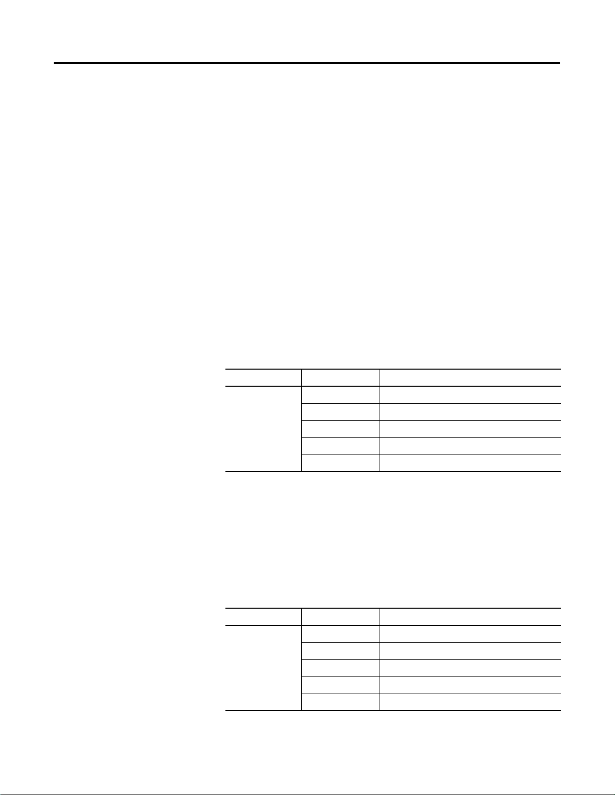
Manual Contents
If you want... See
An overview of the analog input and output modules Chapter 1
Installation and wiring guidelines Chapter 2
Input module addressing, configuration and status information Chapter 3
Output module addressing, configuration and status information Chapter 4
Information on module diagnostics and troubleshooting Chapter 5
Specifications for the input and output modules Appendix A
PROFIBUS information Appendix B
Definitions of terms used in this manual Glossary
1 Publication 1790-UM001A-EN-P - March 2002
Page 6

Preface 2
Related Documentation
The table below provides a listing of publications that contain
important information about CompactBlock LDX systems.
For Read this document Document number
Introduction to CompactBlock LDX Product Profile 1790-PP002
DeviceNet Analog Base D-Shell CompactBlock LDX
1790D-N4CO, -NOC2, -N4VO, -NOV2
DeviceNet Analog Base Terminal Block CompactBlock
LDX 1790D-TN4CO, -TN4VO, -TNOV2, -TNOC2
DeviceNet Cable System Planning and Installation Manual DN-6.7.2
In-depth information on grounding and wiring
Allen-Bradley programmable controllers.
Installation Instructions 1790-IN004
Installation Instructions 1790-IN002
Allen-Bradley Programmable Controller Grounding and
Wiring Guidelines
1770-4.1
If you would like a manual, you can:
• download a free electronic version from the internet at
www.theautomationbookstore.com
• purchase a printed manual by:
– contacting your local distributor or Rockwell Automation
representative
– visiting www.theautomationbookstore.com and placing
your order
– calling 1.800.963.9548 (USA/Canada) or 001.330.725.1574
(Outside USA/Canada)
Conventions Used in This Manual
Publication 1790-UM001A-EN-P - March 2002
The following conventions are used throughout this manual:
• Bulleted lists (like this one) provide information not procedural
steps.
• Numbered lists provide sequential steps or hierarchical
information.
• Italic type is used for emphasis.
• Text in this font indicates words or phrases you should type.
Page 7

Overview
Installation and Wiring
Table of Contents
Chapter 1
How to Use Analog I/O . . . . . . . . . . . . . . . . . . . . . . . . . . 1-1
General Description . . . . . . . . . . . . . . . . . . . . . . . . . . . . . 1-2
Hardware Features. . . . . . . . . . . . . . . . . . . . . . . . . . . . 1-3
General Diagnostic Features . . . . . . . . . . . . . . . . . . . . . 1-4
System Overview . . . . . . . . . . . . . . . . . . . . . . . . . . . . . . . 1-4
System Operation . . . . . . . . . . . . . . . . . . . . . . . . . . . . 1-4
Module Operation . . . . . . . . . . . . . . . . . . . . . . . . . . . . 1-5
Chapter 2
Power Requirements . . . . . . . . . . . . . . . . . . . . . . . . . . . . . 2-1
Module Installation . . . . . . . . . . . . . . . . . . . . . . . . . . . . . . 2-1
Prevent Electrostatic Discharge . . . . . . . . . . . . . . . . . . . 2-2
Environmnet and Enclosure . . . . . . . . . . . . . . . . . . . . . 2-2
Remove Power . . . . . . . . . . . . . . . . . . . . . . . . . . . . . . 2-3
General Considerations . . . . . . . . . . . . . . . . . . . . . . . . . . . 2-3
Reducing Noise . . . . . . . . . . . . . . . . . . . . . . . . . . . . . . 2-3
Protecting the Circuit Board from Contamination. . . . . . 2-3
Installing CompactBlock LDX I/O . . . . . . . . . . . . . . . . . . . 2-4
Set the Node Address on the Base Block . . . . . . . . . . . 2-4
Mount the Base Block . . . . . . . . . . . . . . . . . . . . . . . . . 2-5
Mount the Optional Expansion Blocks . . . . . . . . . . . . . 2-6
Connect the DeviceNet Cable . . . . . . . . . . . . . . . . . . . . 2-7
I/O System Wiring Guidelines . . . . . . . . . . . . . . . . . . . . . . 2-8
General . . . . . . . . . . . . . . . . . . . . . . . . . . . . . . . . . . . . 2-8
Input Modules . . . . . . . . . . . . . . . . . . . . . . . . . . . . . . . 2-8
Output Modules. . . . . . . . . . . . . . . . . . . . . . . . . . . . . . 2-8
Effect of Transducer/Sensor and Cable Length
Impedance on Voltage Input Accuracy . . . . . . . . . . . . . 2-9
Effect of Device and Cable Output Impedance
on Output Module Accuracy. . . . . . . . . . . . . . . . . . . . . 2-11
Wiring the Modules . . . . . . . . . . . . . . . . . . . . . . . . . . . 2-13
1790D-N4C0, 1790D-N4V0 Analog 4 Input Base D-Shell
Modules Wiring . . . . . . . . . . . . . . . . . . . . . . . . . . . . . . 2-15
1790D-TN4C0, 1790D-TN4V0 Analog 4 Input Base Modules
Wiring . . . . . . . . . . . . . . . . . . . . . . . . . . . . . . . . . . . . 2-16
1790D-N0C2, 1790D-N0V2 Analog 2 Output Base D-Shell
Modules Wiring . . . . . . . . . . . . . . . . . . . . . . . . . . . . . . 2-17
1790D-TN0C2, 1790D-TN0V2 Analog 4 Input Base Modules
Wiring . . . . . . . . . . . . . . . . . . . . . . . . . . . . . . . . . . . . 2-18
i Publication 1790-UM001A-EN-P - March 2002
Page 8

Table of Contents ii
Module Data, Status, and Channel
Configuration for Analog Input
Modules
Module Data, Status, and Channel
Configuration for Analog Output
Modules
Chapter 3
Analog Input Image . . . . . . . . . . . . . . . . . . . . . . . . . . . 3-1
Analog Input Data File . . . . . . . . . . . . . . . . . . . . . . . . . 3-2
Analog Input Data File With Discrete Input Expansion
Modules . . . . . . . . . . . . . . . . . . . . . . . . . . . . . . . . . . . 3-3
Analog Input Data Format . . . . . . . . . . . . . . . . . . . . . . . . . 3-7
Configuring Analog Input Module . . . . . . . . . . . . . . . . . . . 3-7
Configuring Analog Modules With RSNetWorx . . . . . . . . . . 3-8
Chapter 4
Analog Output Image. . . . . . . . . . . . . . . . . . . . . . . . . . 4-1
Analog Output Data File . . . . . . . . . . . . . . . . . . . . . . . 4-2
Analog Output Data File With Discrete Output Expansion
Modules . . . . . . . . . . . . . . . . . . . . . . . . . . . . . . . . . . . 4-3
Analog Output Data Format. . . . . . . . . . . . . . . . . . . . . . . . 4-7
Output Fault and Idle States . . . . . . . . . . . . . . . . . . . . . . . 4-7
Configuring Analog Output Module . . . . . . . . . . . . . . . . . . 4-8
Using RSNetWorx for DeviceNet. . . . . . . . . . . . . . . . . . 4-8
Module Diagnostics and
Troubleshooting
Specifications
Chapter 5
Safety Considerations . . . . . . . . . . . . . . . . . . . . . . . . . . . . 5-1
Indicator Lights . . . . . . . . . . . . . . . . . . . . . . . . . . . . . . 5-1
Activating Devices When Troubleshooting . . . . . . . . . . 5-2
Stand Clear of the Machine. . . . . . . . . . . . . . . . . . . . . . 5-2
Program Alteration. . . . . . . . . . . . . . . . . . . . . . . . . . . . 5-2
Safety Circuits . . . . . . . . . . . . . . . . . . . . . . . . . . . . . . . 5-2
Module Operation vs. Channel Operation . . . . . . . . . . . . . 5-3
Power-up Diagnostics . . . . . . . . . . . . . . . . . . . . . . . . . . . . 5-3
Module Status . . . . . . . . . . . . . . . . . . . . . . . . . . . . . . . 5-3
Network Status . . . . . . . . . . . . . . . . . . . . . . . . . . . . . . 5-3
Channel Diagnostics . . . . . . . . . . . . . . . . . . . . . . . . . . . . . 5-4
Out-of-Range Detection (Input Modules Only) . . . . . . . 5-4
Open-Circuit Detection (Input Module Only) . . . . . . . . 5-4
Analog Input Module Error Definition Table. . . . . . . . . . . . 5-5
Module Errors. . . . . . . . . . . . . . . . . . . . . . . . . . . . . . . . . . 5-5
Channel LED Indicator Operation . . . . . . . . . . . . . . . . . . . 5-6
Contacting Rockwell Automation . . . . . . . . . . . . . . . . . . . . 5-7
Appendix A
DeviceNet Analog Base Terminal Block . . . . . . . . . . . . A-1
4-Channel Analog Current Input Module. . . . . . . . . . . . A-3
2-Channel Analog Current Output Module . . . . . . . . . . A-4
4-Channel Analog Voltage Input Module. . . . . . . . . . . . A-5
2-Channel Analog Voltage Output Module . . . . . . . . . . A-6
Publication 1790-UM001A-EN-P - March 2002
Page 9

PROFIBUS Modules Installation,
Wiring, Module Data, Status and
Channel Configuration
Glossary
Table of Contents iii
Appendix B
Power Requirements . . . . . . . . . . . . . . . . . . . . . . . . . . . . . B-1
Module Installation . . . . . . . . . . . . . . . . . . . . . . . . . . . . . . B-2
Prevent Electrostatic Discharge . . . . . . . . . . . . . . . . . . . B-2
Environment and Enclosure . . . . . . . . . . . . . . . . . . . . . B-3
Remove Power . . . . . . . . . . . . . . . . . . . . . . . . . . . . . . B-4
General Considerations . . . . . . . . . . . . . . . . . . . . . . . . . . . B-4
Reducing Noise . . . . . . . . . . . . . . . . . . . . . . . . . . . . . . B-4
Protecting the Circuit Board from Contamination. . . . . . B-4
Installing CompactBlock LDX I/O . . . . . . . . . . . . . . . . . . . B-5
Set the Station Address on the Base Block . . . . . . . . . . B-5
Mount the Base Block . . . . . . . . . . . . . . . . . . . . . . . . . B-5
Connect the PROFIBUS DP Terminal Connector . . . . . . B-8
Connect Power to the Block. . . . . . . . . . . . . . . . . . . . . B-9
Connecting I/O Wiring . . . . . . . . . . . . . . . . . . . . . . . . . . B-10
General Guidelines . . . . . . . . . . . . . . . . . . . . . . . . . . B-10
Guidelines for Input Modules . . . . . . . . . . . . . . . . . . . B-10
Guidelines for Output Modules . . . . . . . . . . . . . . . . . B-10
Wiring the Modules . . . . . . . . . . . . . . . . . . . . . . . . . . B-11
1790P-TN4C0 Data Structure . . . . . . . . . . . . . . . . . . . . . . B-15
Analog Input Image . . . . . . . . . . . . . . . . . . . . . . . . . . B-15
1790P-TNOC2 Data Structure. . . . . . . . . . . . . . . . . . . . . . B-16
Analog Output Image. . . . . . . . . . . . . . . . . . . . . . . . . B-16
Output Fault and Idle States . . . . . . . . . . . . . . . . . . . . . . B-16
Configuring PROFIBUS Analog Modules . . . . . . . . . . . . . B-16
Configuring Analog Modules with the SST PROFIBUS
Configuration Tool . . . . . . . . . . . . . . . . . . . . . . . . . . . . . B-17
Downloading Configuration. . . . . . . . . . . . . . . . . . . . . . . B-21
PROFIBUS DP Specifications . . . . . . . . . . . . . . . . . . . . . . B-24
Summary . . . . . . . . . . . . . . . . . . . . . . . . . . . . . . . . . . . . B-25
Index
Publication 1790-UM001A-EN-P - March 2002
Page 10

Table of Contents iv
Publication 1790-UM001A-EN-P - March 2002
Page 11
Chapter
Overview
This chapter explains how analog data is used, and describes
CompactBlock LDX analog input and output modules. Included is
information about:
• the use of analog I/O
• the modules’ hardware and diagnostic features
• an overview of the analog input system operation
• an overview of the analog output system operation
1
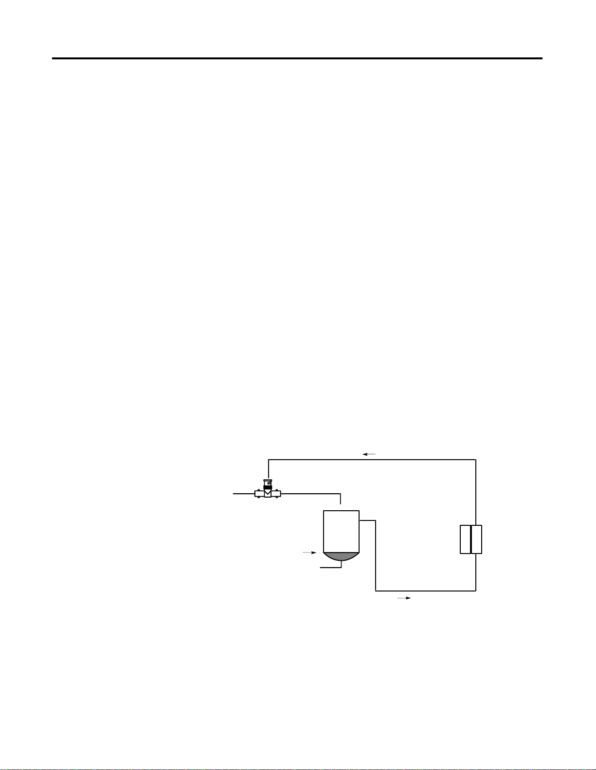
How to Use Analog I/O
Analog refers to the representation of numerical quantities by the
measurement of continuous physical variables. Analog applications
are present in many forms. The following application shows a typical
use of analog data.
In this application, the processor controls the amount of fluid in a
holding tank by adjusting the valve opening. The valve is initially
open 100%. As the fluid level in the tank approaches the preset point,
the processor modifies the output to close the valve 90%, 80%, and so
on, continuously adjusting the valve to maintain the fluid level.
Analog output
wired to valve
Valve
Controller
Level Sensor
Analog input wired
to tank
Analog I/O
Module
1 Publication 1790-UM001A-EN-P - March 2002
Page 12

1-2 Overview
General Description
The analog input module converts and digitally stores analog data for
retrieval by controllers, such as the SLC-500 programmable controller.
The module supports connections from any combination of up to four
voltage or current analog sensors. The four high-impedance input
channels can be wired as single-ended inputs.
The output module provides two single-ended analog output
channels, either voltage or current, depending on the module
selected.
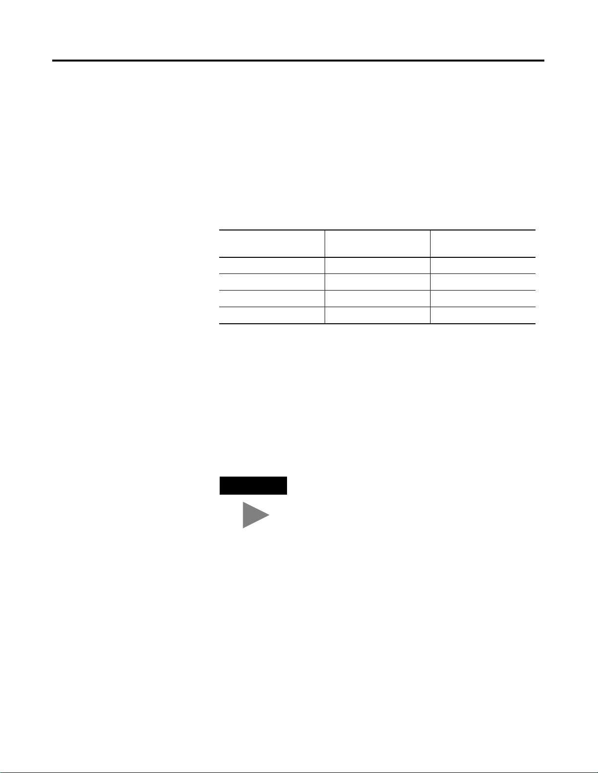
Table 1.1 lists the CompactBlock LDX module types and
corresponding operating ranges:
Table 1.1
CompactBlock LDX Module Types and Operating Ranges
CompactBlock LDX
Module
1790D-N4CO
1790D-TN4CO
1790D-NOC2
1790D-TNOC2
Type: Operating Range:
Current Input 4-20mA
or
0-20mA
Current Output 0-20mA
1790D-N4VO
1790D-TN4VO
1790D-NOV2
1790D-TNOV2
Voltage Input 0-10V dc
Voltage Output 0-10V dc
Each analog base module supports up to two CompactBlock LDX
discrete expansion modules.
Publication 1790-UM001A-EN-P - March 2002
Page 13
DIN rail slot
DeviceNet
network
connector
Overview 1-3
Hardware Features
The modules contain either removable D-shell connectors or fixed
terminal blocks. The CompactBlock LDX four input channels are
single-ended. The CompactBlock LDX two output channels are also
single-ended. Module configuration is normally done via the
controller’s programming software. In addition, some controllers
support configuration via the user program.
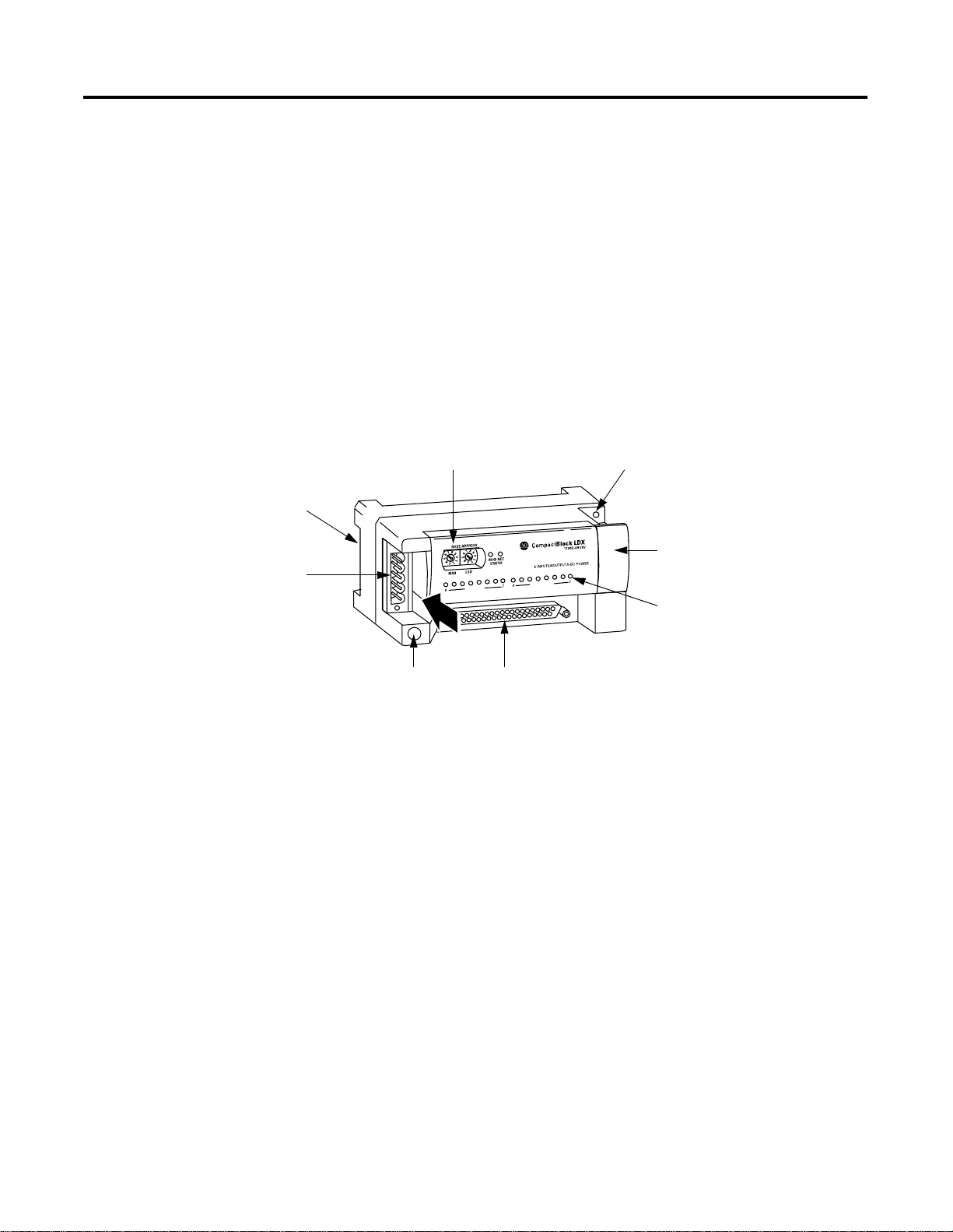
Figure 1.1 shows the CompactBlock LDX analog modules’ hardware
features.
Figure 1.1
Node
address
switches
Panel
mount
hole
Expansion connector
under cover
Module
indicators
Panel
mount
hole
Analog I/O
connections
(D-shell shown)
43218
Publication 1790-UM001A-EN-P - March 2002
Page 14

1-4 Overview
General Diagnostic Features
The CompactBlock LDX modules contain diagnostic features that can
help you identify the source of problems that may occur during
power-up or during normal channel operation. These power-up and
channel diagnostics are explained in Chapter 5, Module Diagnostics
and Troubleshooting.
System Overview
The modules communicate to the controller through the DeviceNet
network. Module power is derived from DeviceNet. Additionally, the
analog I/O requires 24V dc field power separate from DeviceNet.
CompactBlock LDX analog bases support up to two discrete LDX
expansion modules.
System Operation
At power-up, the analog base module performs a check of its internal
circuits, memory, and basic functions. During this time, the module
status LED remains off. If no faults are found during power-up
diagnostics, the module status LED is turned on.
After power-up checks are complete, the module waits for valid
channel configuration data. If an invalid configuration is detected, the
module generates a configuration error. Once a channel is properly
configured and enabled, it begins the analog-to-digital or
digital-to-analog conversion process.
Publication 1790-UM001A-EN-P - March 2002
Page 15
Overview 1-5
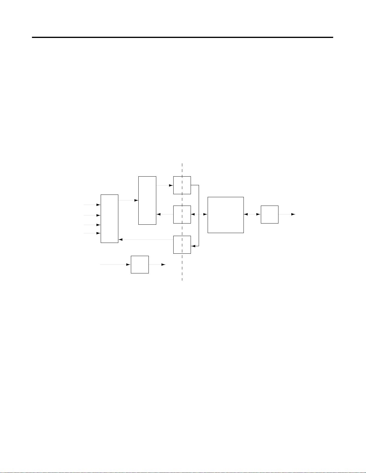
Module Operation
Input Module
The input module’s input circuitry consists of four analog inputs
multiplexed into a single analog-to-digital (A/D) converter. The A/D
converter reads the selected input signal and converts it to a digital
value that is presented to the network. The multiplexer sequentially
switches each input channel to the module’s A/D converter. Figure 1.2
on page 1-5 shows a block diagram of the circuitry.
Figure 1.2
Isolation
Input 0
Input 1
Input 2
Input 3
24V dc
Field
Power
Data
Signal
A/D
Control
Multiplexer
Select
Analog
power
supply
Analog
power
Optocouplers
Microcontroller
DeviceNetXCVR
43219
Each time the input module reads a channel, the module tests that
analog data value for an overrange or underrange condition. If such a
condition is detected, a unique bit is set in the channel status word.
The channel status word is described in Chapter 4, Module Data,
Status, and Channel Configuration for Analog Output Modules.
Publication 1790-UM001A-EN-P - March 2002
Page 16
1-6 Overview
Output 0
Analog
output
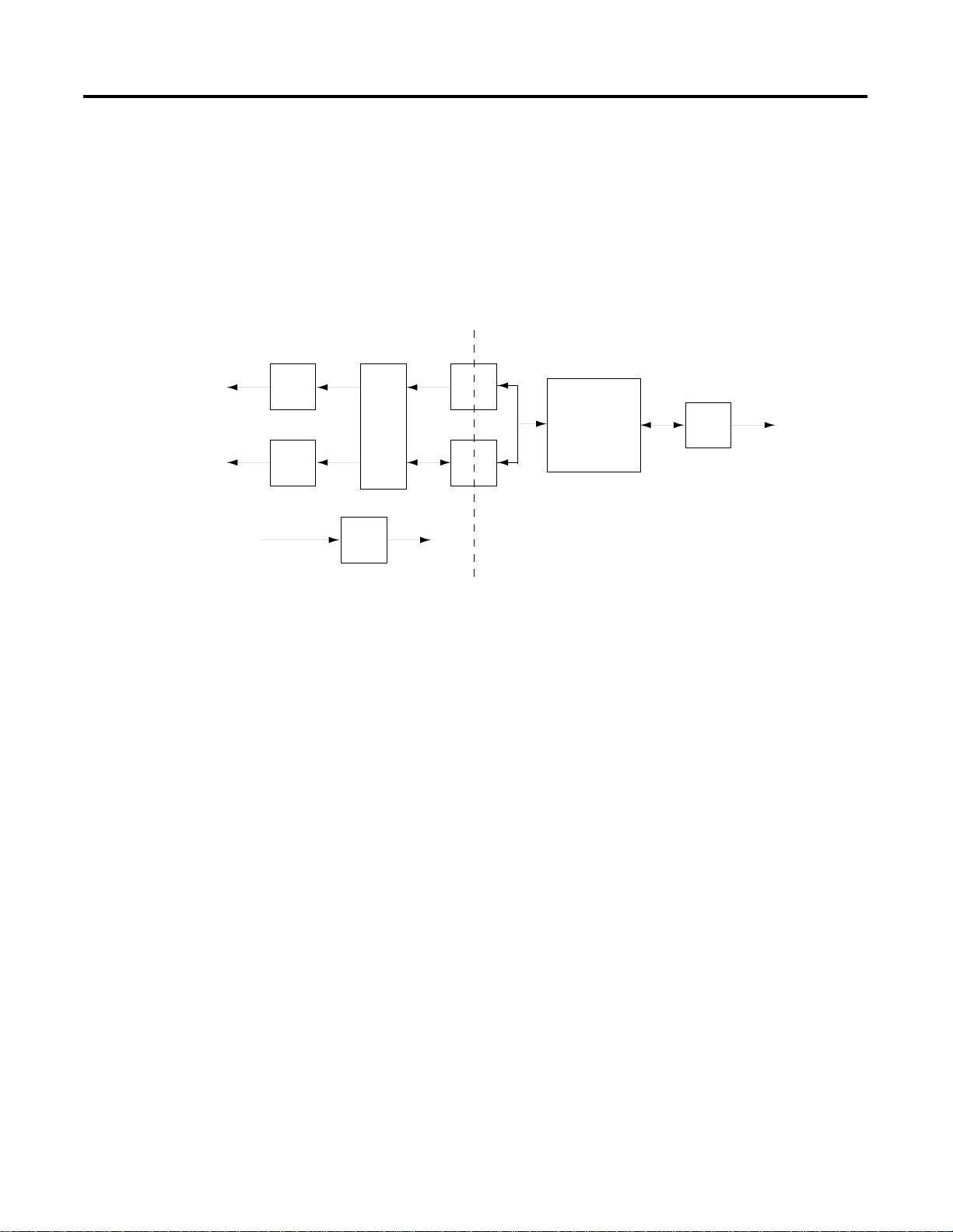
Output Module
The output module uses a digital-to-analog (D/A) converter to read
the digital output data from the network and convert it to an analog
output signal. Figure 1.3 below shows a block diagram of the
circuitry.
Figure 1.3
Isolation
Optocouplers
Data
Output 1
24V dc
Field
Power
Analog
output
Analog
power
supply
D/A
Control
Analog
power
Microcontroller
DeviceNetXCVR
43220
Publication 1790-UM001A-EN-P - March 2002
Page 17

Installation and Wiring
This chapter tells you how to:
• determine the power requirements for the modules
• avoid electrostatic damage
• install the module
• wire the module’s terminal block
• wire input devices
• wire output devices
Chapter
2
Power Requirements
Module Installation
The modules receive power through the DeviceNet network and from
an auxilary 24V dc field supply. The maximum power drawn by the
modules is shown in Table 2.1.
Table 2.1
CompactBlock LDX Module Power Requirements
Voltage Range: Power:
DeviceNet Power: 11-28.8 V dc 1.2W @ 28.8V dc
Auxilary 24V dc Field Power: 21.6-26.4V dc 1.5W @ 26.4V dc
CompactBlock LDX is suitable for use in an industrial environment
when installed in accordance with these instructions. Specifically, this
equipment is intended for use in clean, dry environments (Pollution
(1)
degree 2
) and to circuits not exceeding Over Voltage Category II
(IEC 60664-1).
(3)
(2)
(1)
Pollution Degree 2 is an environment where, normally, only non-conductive pollution occurs except that
occasionally a temporary conductivity caused by condensation shall be expected.
(2)
Over Voltage Category II is the load level section of the electrical distribution system. At this level transient
voltages are controlled and do not exceed the impulse voltage capability of the product’s insulation.
(3)
Pollution Degree 2 and Over Voltage Category II are International Electrotechnical Commission (IEC)
designations.
1 Publication 1790-UM001A-EN-P - March 2002
Page 18
2-2 Installation and Wiring
Prevent Electrostatic Discharge
ATTENTION
!
Electrostatic discharge can damage integrated circuits or
semiconductors if you touch analog I/O module bus
connector pins or the terminal block on the input module.
Follow these guidelines when you handle the module:
• Touch a grounded object to discharge static potential.
• Wear an approved wrist-strap grounding device.
• Do not touch the bus connector or connector pins.
• Do not touch circuit components inside the module.
• If available, use a static-safe work station.
• When it is not in use, keep the module in its box.
Environmnet and Enclosure
ATTENTION
!
This equipment is intended for use in a Pollution Degree 2
industrial environment, in overvoltage Category II
applications (as defined in IEC publication 60664-1), at
altitudes up to 2000 meters without derating.
This equipment is considered Group 1, Class A industrial
equipment according to IEC/CISPR Publication 11.
Without appropriate precautions, there may be potential
difficulties ensuring electromagnetic compatibility in other
environments due to conducted as well as radiated
disturbance.
This equipment is supplied as "open type" equipment. It
must be mounted within an enclosure that is suitably
designed for those specific environmental conditions that
will be present and appropriately designed to prevent
personal injury resulting from accessibility to live parts.
The interior of the enclosure must be accessible only by
the use of a tool. Subsequent sections of this publication
may contain additional information regarding specific
enclosure type ratings that are required to comply with
certain product safety certifications.
Publication 1790-UM001A-EN-P - March 2002
See NEMA Standards publication 250 and IEC publication
60529, as applicable, for explanations of the degrees of
protection provided by different types of enclosure. Also,
see the appropriate sections in this publication, as well as
the Allen-Bradley publication 1770-4.1 ("Industrial
Automation Wiring and Grounding Guidelines"), for
additional installation requirements pertaining to this
equipment.
Page 19
Remove Power
Installation and Wiring 2-3
General Considerations
ATTENTION
Remove power before removing or inserting this
module or an expansion module. When you remove
or insert a module with power applied, an electrical
arc may occur. An electrical arc can cause personal
injury or property damage by:
!
• sending an erroneous signal to your system’s field
devices, causing unintended machine motion
• causing an explosion in a hazardous environment
Electrical arcing causes excessive wear to contacts on
both the module and its mating connector and may
lead to premature failure.
Reducing Noise
Most applications require installation in an industrial enclosure to
reduce the effects of electrical interference. Analog inputs and outputs
are highly susceptible to electrical noise. Electrical noise coupled to
the analog inputs will reduce the performance (accuracy) of the
module.
Group your modules in the enclosure to minimize adverse effects
from radiated electrical noise and heat. Consider the following
conditions when selecting a location for the analog module. Position
the module:
• away from sources of electrical noise such as hard-contact
switches, relays, and AC motor drives
• away from modules which generate significant radiated heat.
In addition, route shielded, twisted-pair analog input and output
wiring away from any high voltage I/O wiring.
Protecting the Circuit Board from Contamination
The printed circuit boards of the analog modules must be protected
from dirt, oil, moisture, and other airborne contaminants. To protect
these boards, the system must be installed in an enclosure suitable for
the environment. The interior of the enclosure should be kept clean
and the enclosure door should be kept closed whenever possible.
Publication 1790-UM001A-EN-P - March 2002
Page 20

2-4 Installation and Wiring
Installing CompactBlock LDX I/O
Follow these steps to install the block:
1. Set the Node Address on the Base Block
2. Mount the Base Block
3. Mount the Optional Expansion Blocks
4. Connect the DeviceNet Cable
Set the Node Address on the Base Block
Each base block comes with its internal program set for node address
63. To reset the node address, adjust the switches on the front of the
block. The two switches are most significant digit (MSD) and least
significant digit (LSD). The switches can be set between 00 and 63.
The rotary switches are read at block power up only. Switch settings
between 64 and 99 cause the block to use the last valid node address stored
internally
.
Node Address is set to 11
Figure 2.1
NODE ADDRESS
MOD NET
STATUS
LSDMSD
43216
The node address may also be set through RSNetWorx for DeviceNet
or a similar configuration tool. When software configuration is used
for the node address, the switches must be set between 64 and 99.
Publication 1790-UM001A-EN-P - March 2002
Page 21
Installation and Wiring 2-5
Mount the Base Block
You can mount the base block to a panel or DIN rail. We recommend
that you ground the panel or DIN rail before mounting the block.
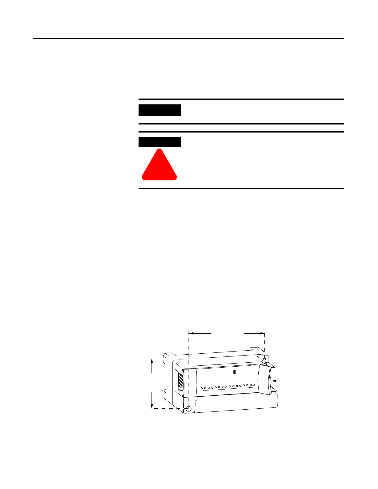
IMPORTANT
WARNING
The analog base module can accommodate a
maximum of two discrete expansion modules.
When used in a Class I, Division 2, hazardous
location, this equipment must be mounted in a
suitable enclosure with proper wiring method that
complies with the governing electrical codes.
!
Panel Mounting
1. Place the block against the panel where you want to mount it.
2. Gently pull and position the expansion cover to the left.
3. Place a center punch, nail or similar device through the
mounting holes in the block and make two marks on the panel
(lower left and upper right corners of the module).
4. Remove the block and drill two holes in the panel to
accommodate each of the mounting screws.
5. Replace the block on the panel and place a screw through each of the
two mounting holes. Tighten the screws until the block is firmly in
place.
95 mm
3.74 in
X
LD
k
c
lo
CompactB
1790-16BVOX
41 mm
1.6 in
EXPANSION UNIT
0
0
7
16 INPUTS-DCPOWER
7
Expansion
Cover
Publication 1790-UM001A-EN-P - March 2002
Page 22
2-6 Installation and Wiring
Compact
PULL
PULL
Compact
PULL
PULL
Compact
PULL
PULL
Compact
Block LDX
PULL
PULL
Compact
PULL
PULL
Compact
PULL
PULL
Compact
PULL
PULL
DIN Rail Mounting
1. Hook the top of slot of the block over the DIN Rail.
2.
Pull down on the locking lever while pressing the block against the
rail.
f
Locking Lever
3. Push up on the locking lever to secure the block to the rail
when block is flush against the rail.
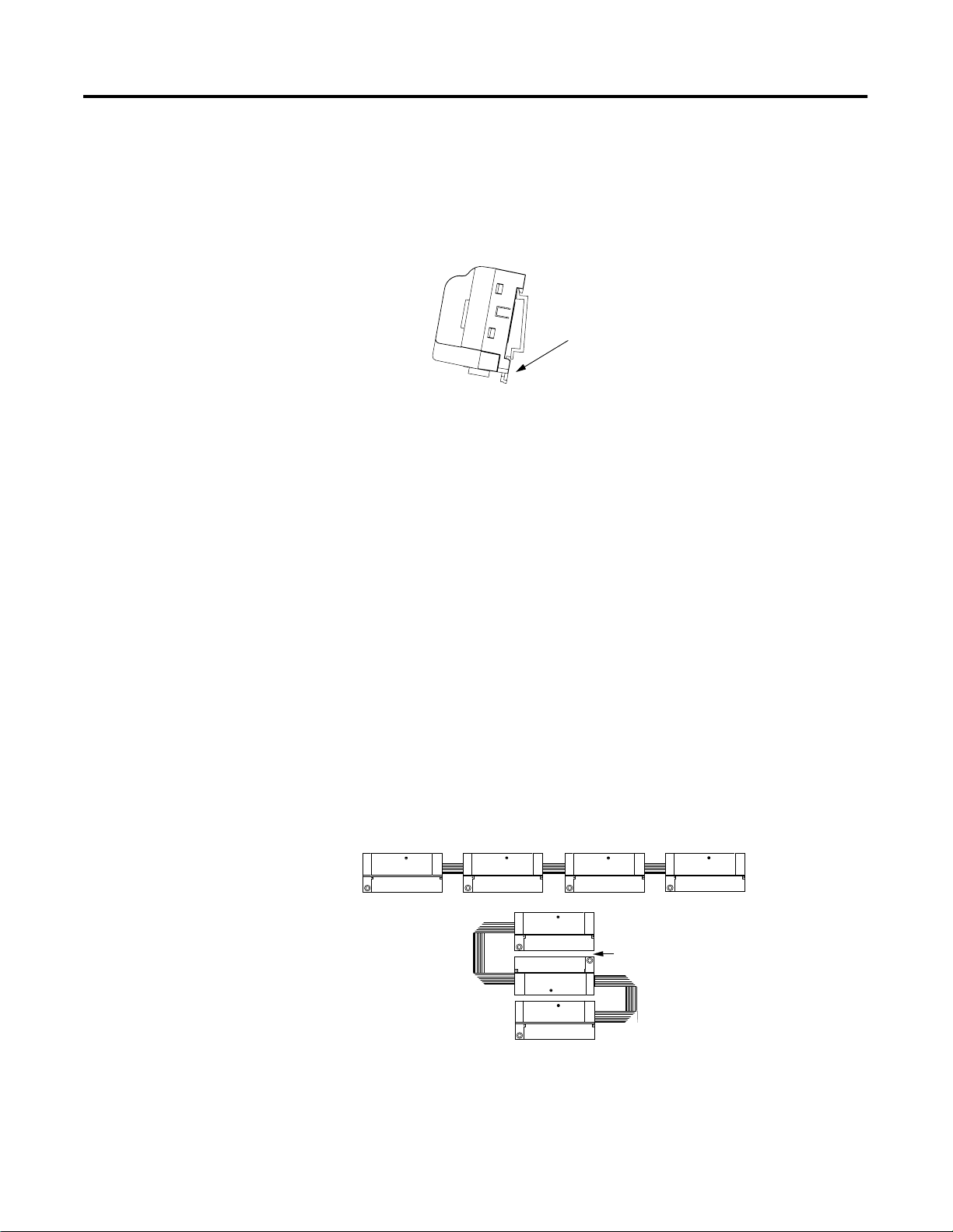
Mount the Optional Expansion Blocks
Mount the expansion block by connecting it to a previously-installed
CompactBlock LDX I/O base or expansion block.
Beginning with the base block, you can mount your expansion blocks
horizontally or vertically:
• horizontally (left to right) - add expansion blocks in a
end-to-end configuration
• vertically (up or down) - add expansion blocks either up or
down in a back-to-back configuration. In this configuration, you
must use the optional 15cm ribbon cable (1790-15CMCBL) and
alternately position the blocks in a right-side up, upside-down
fashion.
Compact
Block LDX
Compact
Block LDX
EXPANSION UNIT
PULL
RIGHT SIDE UP
Horizontal mounting
EXPANSION UNIT
PULL
PULL
RIGHT SIDE UP
Vertical mounting
Compact
Block LDX
PULL
PULL
PULL
PULL
Compact
EXPANSION UNIT
RIGHT SIDE UP
UPSIDE DOWN
Compact
Block LDX
Compact
EXPANSION UNIT
EXPANSION UNIT
PULL
RIGHT SIDE UP
Block LDX
PULL
EXPANSION UNIT
Block LDX
PULL
Compact
Block LDX
The longer expansion cable
(1790-15CMCBL) will allow
up to 7cm of space in between
blocks.
PULL
EXPANSION UNIT
PULL
PULL
PULL
RIGHT SIDE UP
RIGHT SIDE UP
You can mount your blocks on a panel or DIN rail as described in the
previous section.
Publication 1790-UM001A-EN-P - March 2002
Page 23
Installation and Wiring 2-7
Connect the DeviceNet Cable
Follow these procedures when connecting the DeviceNet cable to the
base block.
The required DeviceNet connector is not supplied with the block you must purchase it separately. There are three types of connectors
that you can order directly from Rockwell Automation or your local
distributor:
• 1799-DNETCON - 5-position open style connector
• 1799-DNETSCON - 5-position open style connector with locking
screws
• 1799-DNC5MMS - 5-position open style to 12mm connector with
locking screws
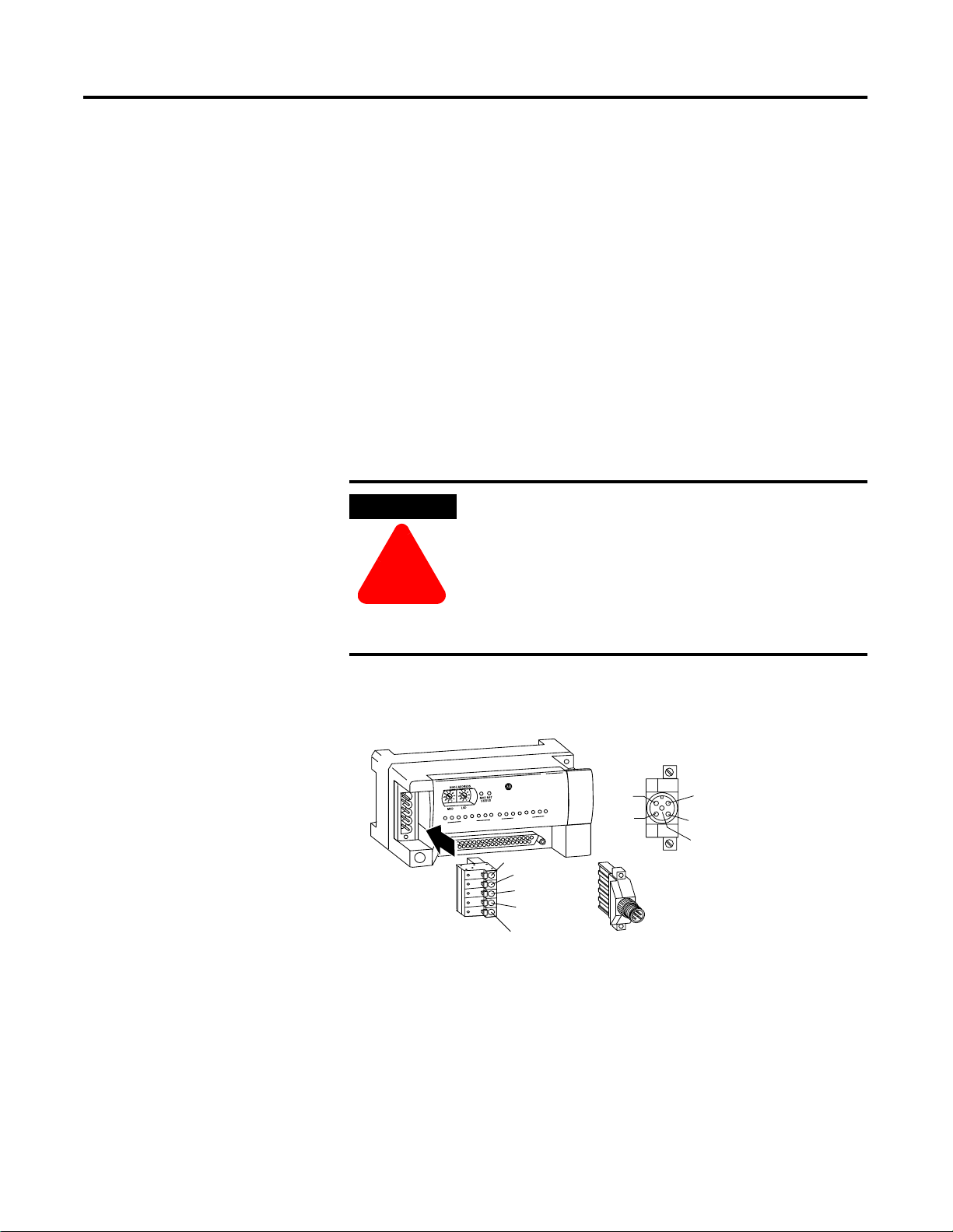
WARNING
If you connect or disconnect the DeviceNet cable
with power applied to this module or any device on
the network, an electrical arc can occur. This could
cause an explosion in hazardous location
!
installations.
Be sure that power is removed or the area is
nonhazardous before proceeding.
Connect the DeviceNet wiring (drop line) to one of the DeviceNet
connectors as shown below. A color-coded wiring diagram is also printed
next to the connector on the left side of the module
CompactBlock LDX
V
8
V
B
8
-
D
0
9
7
Wiring Diagram for
1799-DNETCON
1
W
O
P
C
D
-
S
T
U
P
T
U
O
8
/
S
T
U
P
N
I
8
7
0
7
0
V+ Red
Can_H White
Drain/Shield
V+ Red
R
E
V- Black
Wiring Diagram for
1799-DNC5MMS
Can_L Blue
V- Black
Drain/Shield
Can_H White
Can_L Blue
Once you have properly wired the drop line to the connector, attach
the connector to the block. If applicable, use the locking screws on
the connector to fasten it to the block.
Publication 1790-UM001A-EN-P - March 2002
Page 24

2-8 Installation and Wiring
I/O System Wiring Guidelines
Consider the following when wiring your system:
General
• All module commons (COM) are connected in the analog
module. The analog common (COM) is not connected to earth
ground inside the module.
• Channels are not isolated from each other.
• Do not use the analog module’s NC terminals as connection
points.
• To ensure optimum accuracy, limit overall cable impedance by
keeping your cable as short as possible. Locate the I/O system
as close to your sensors or actuators as your application will
permit.
• Use Belden™ 8761, or equivalent, shielded wire.
• Keep shield connection to ground as short as possible.
• Under normal conditions, the drain wire and shield junction
must be connected to earth ground via a panel or DIN rail
mounting screw at the analog I/O module end.
(1)
Input Modules
• If multiple power supplies are used with analog inputs, the
power supply commons must be connected together.
• The module does not provide loop power for analog inputs. Use
a power supply that matches the input transmitter specifications.
Output Modules
• Voltage outputs (CH0 and CH1) of the 1790D-NOV2/TNOV2
modules are referenced to COM. Load resistance for a voltage
output channel must be equal to or greater than 1K
• Current outputs (CH0 and CH1) of the 1790D-NOC2/TNOC2
modules source current that returns to COM. Load resistance for
a current output channel must remain between 0 and 600
Ω.
Ω.
Publication 1790-UM001A-EN-P - March 2002
(1)
In environments where high-frequency noise may be present, it may be necessary to directly ground cable
shields to earth at the module end and via a 0.1µF capacitor at the sensor end.
Page 25
Installation and Wiring 2-9
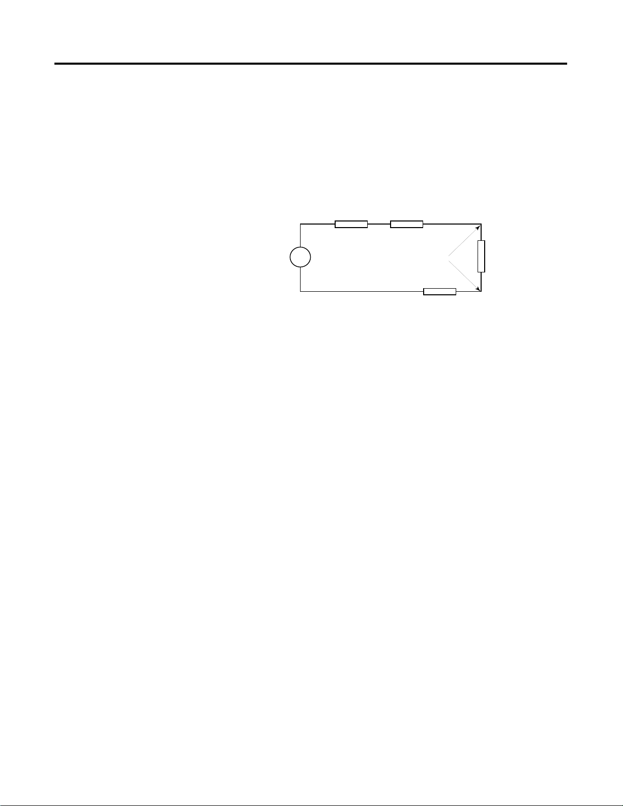
Effect of Transducer/Sensor and Cable Length Impedance on
Voltage Input Accuracy
For voltage inputs, the length of the cable used between the
transducer/sensor and the module can affect the accuracy of the data
provided by the module.
RcRs
+
Ri
Where:
Vs
V in
-
Rc
Rc = DC resistance of the cable (each conductor) depending on
cable length
Rs = Source impedance of analog transducer/sensor output
Ri = Impedance of the voltage input (500K
Ω for
1790D-N4VO/TN4VO)
Vs = Voltage source (voltage at the transducer/sensor input
device)
Vin = Measured potential at the module input
%Ai = Percent added inaccuracy in a voltage-based system due
to source and cable impedance.
Ri Vs
Vin
-------------------------------------------------------
=
Rs 2 Rc×()Ri++[]
×[]
Publication 1790-UM001A-EN-P - March 2002
Page 26
2-10 Installation and Wiring
For example, for Belden 8761 two conductor, shielded cable:
Rc = 16
Ω/1000 ft
Rs = 0 (ideal source)
Vin
%Ai 1
Table 2.2
Effect of Cable Length on Input Accuracy
Length of Cable (m) dc resistance of the
cable, Rc (
50 2.625 0.00105%
100 5.25 0.00210%
200 10.50 0.00420%
300 15.75 0.00630%
---------
–
Vs
100×=
Ω)
Accuracy impact at the
input module
As input source impedance (Rs) and/or resistance (dc) of the cable
(Rc) get larger, system accuracy decreases. If you determine that the
inaccuracy error is significant, implementing the following equation in
the control program can compensate for the added inaccuracy error
due to the impedance of the source and cable.
Vs Vin
Rs 2 Rc
-------------------------------------------------------
×=
×()Ri++[]
Ri
Publication 1790-UM001A-EN-P - March 2002
TIP
In a current loop system, source and cable
impedance do not impact system accuracy.
Page 27
Installation and Wiring 2-11
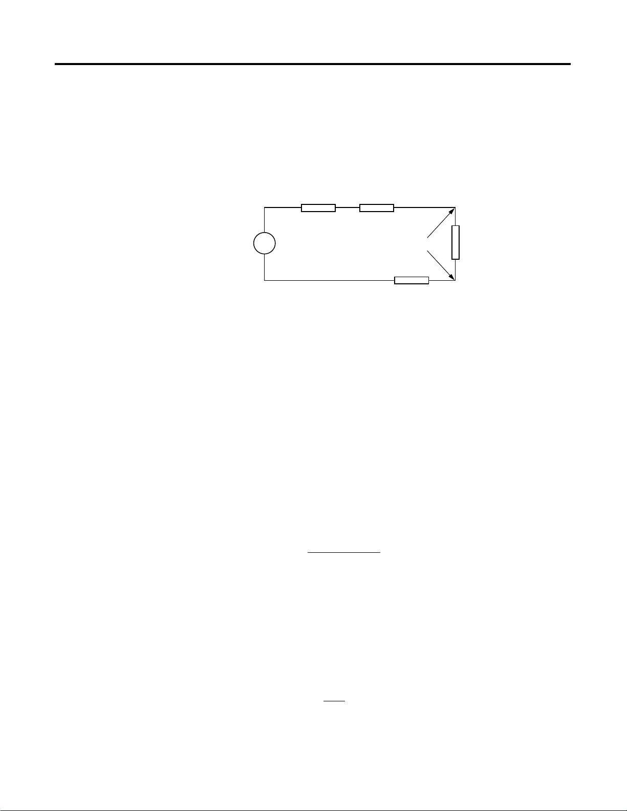
Effect of Device and Cable Output Impedance on Output Module
Accuracy
The maximum value of the output impedance is shown in the
example below, because it creates the largest deviation from an ideal
voltage source.
Rs Rc
+
+
Vs
–
Where:
Vload Rload
-
Rc
Rc
Ri
43266
Rc = DC resistance of the cable (each conductor)
depending on cable length
Rs = Source impedance of 1790D-NOV2/TNOV2 (0.5
R
= Impedance of the load device
load
Ω)
Vs = Voltage at the output of 1790D-NOV2/TNOV2
= Measured potential at the load device
V
load
%Ai = Percent added inaccuracy in a voltage-based system due
to source and cable impedance.
[R
x Vs]
load
V
=
load
[Rs + (2 x Rc) + R
load
]
For example, for Belden 8761 two conductor, shielded cable and a
1790D-NOV2/TNOV2 module:
Rc = 16
Ω/1000 ft
Rs = 0.5
%AV
load
Ω
V
= (1 - ) x 100
load
V
s
Publication 1790-UM001A-EN-P - March 2002
Page 28
2-12 Installation and Wiring
Table 2.3
Effect of Output Impedance and Cable Length on Accuracy
Length of Cable
(m)
dc resistance of
the cable, Rc (
Ω)
Accuracy impact at the load
Ω 10,000Ω 100,000Ω
1,000
1 0.0525 0.0605% 0.00605% 0.000605%
10 0.525 0.155% 0.0155% 0.00155%
50 2.625 0.575% 0.0575% 0.00575%
100 5.25 1.1% 0.11% 0.011%
As output impedance (Rs) and/or resistance (dc) of the cable (Rc) get
larger, system accuracy decreases. If you determine that the
inaccuracy error is significant, implementing the following equation in
the control program can compensate for the added inaccuracy error
due to the impedance of the output module and cable.
+ (2 x Rc) + R
[R
Vs = V
TIP
s
x
load
[R
In a current loop system, source and cable
impedance do not impact system accuracy.
load
load
]
Publication 1790-UM001A-EN-P - March 2002
Page 29
Wiring the Modules
Installation and Wiring 2-13
ATTENTION
To prevent shock hazard, care should be taken when
wiring the module to analog signal sources. Before
wiring any analog module, disconnect power from
the system power supply and from any other source
to the analog module.
!
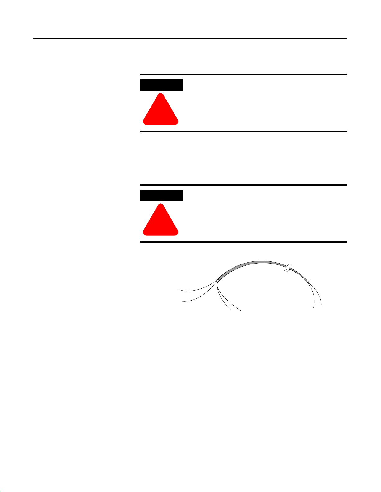
After the analog module is properly installed, follow the wiring
procedure below. To ensure proper operation and high immunity to
electrical noise, always use Belden™ 8761 (shielded, twisted-pair) or
equivalent wire.
ATTENTION
Never connect a voltage or current source to an
analog output channel.
!
signal wire
signal wire
drain wire
cable
foil shield
signal wire
Cut foil shield
and drain wire
signal wire
Publication 1790-UM001A-EN-P - March 2002
Page 30
2-14 Installation and Wiring
To wire your module follow these steps.
1. At each end of the cable, strip some casing to expose the
individual wires.
2. Trim the signal wires to 2-inch lengths. Strip about 3/16 inch (5
mm) of insulation away to expose the end of the wire.
ATTENTION
Be careful when stripping wires. Wire fragments that
fall into a module could cause damage at power up.
!
3. At one end of the cable, twist the drain wire and foil shield
together.
Under normal conditions, this drain wire and shield junction
must be connected to earth ground, via a panel or DIN rail
mounting screw at the analog I/O module end. Keep the length
of the drain wire as short as possible.
In environments where high frequency noise may be present, it
may be necessary to ground the cable shields to earth at the
module and via a 0.1µF capacitor at the sensor end for analog
inputs and at the load end for analog outputs.
4. At the other end of the cable, cut the drain wire and foil shield
back to the cable.
Publication 1790-UM001A-EN-P - March 2002
5. Connect the signal wires to the terminal block as shown in
analog input wiring on page 2-15 and page 2-16 and analog
output wiring on page 2-17 and page 2-18.
6. Connect the other end of the cable to the analog input or output
device.
7. Repeat steps 1 through 5 for each channel on the module.
Page 31

Installation and Wiring 2-15
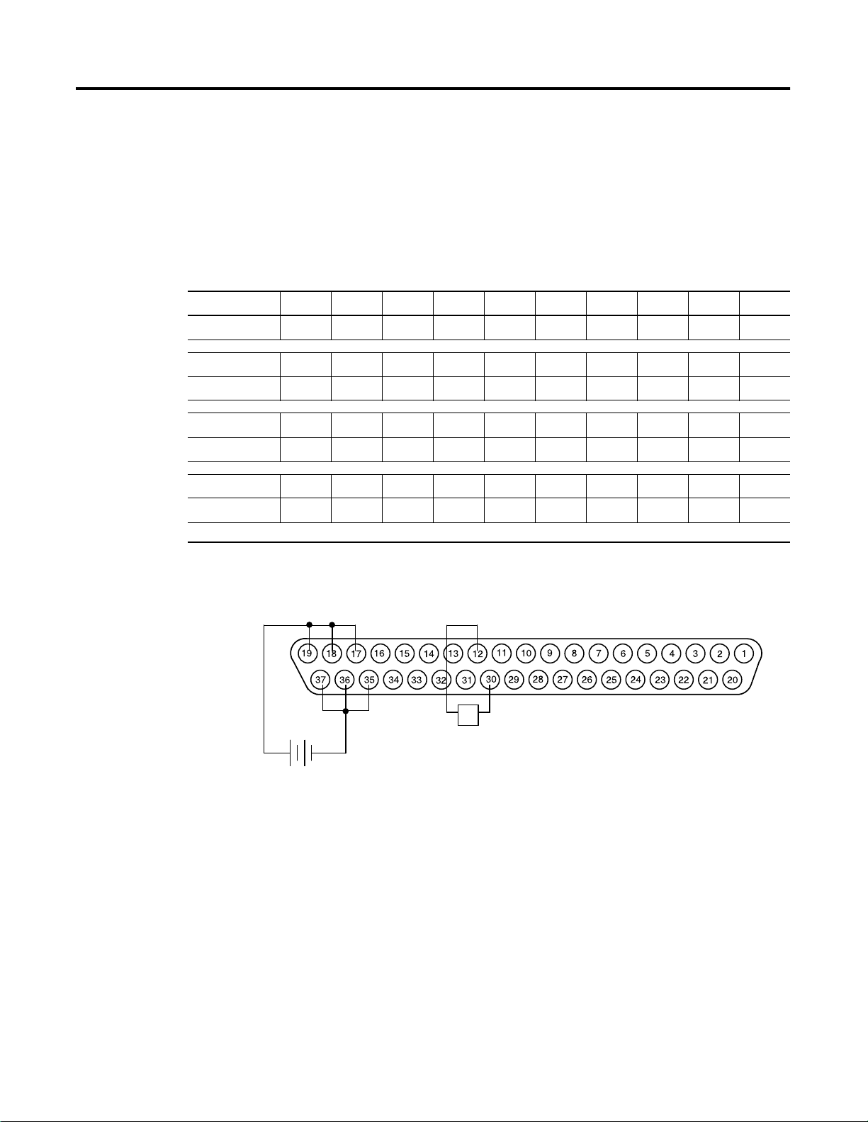
1790D-N4C0, 1790D-N4V0 Analog 4 Input Base D-Shell Modules
Wiring
Table 2.4 lists the module pin descriptions. Figure 2.2 and Figure 2.3
show how to wire each module.
Table 2.4
1790D-N4C0 and 1790D-N4V0 Module Pin Descriptions
Pin Number 12345678910
Description: NC NC NC NC NC CH3 NC CH2 NC CH1
Pin Number: 11 12 13 14 15 16 17 18 19 20
Description: NC CH0 NC NC NC NC +24V +24V +24V NC
Pin Number 21 22 23 24 25 26 27 28 29 30
Description: NC NC NC COM NC COM NC COM NC COM
Pin Number: 31 32 33 34 35 36 37
Description: NC NC NC NC GND GND GND
NC = No Connect +24V = Field Power (+) 24V dc GND = Field Power (-) GND
+ –
24V dc
+ –
24V dc
+24V
GND
+24V
GND
Figure 2.2 Example of Input Wiring to the 1790D-N4C0 Module
CH0
+ –
mA
COM
Figure 2.3 Example of Input Wiring to the 1790D-N4V0 Module
CH0
+ –
COM
V
43221
43221
Publication 1790-UM001A-EN-P - March 2002
Page 32

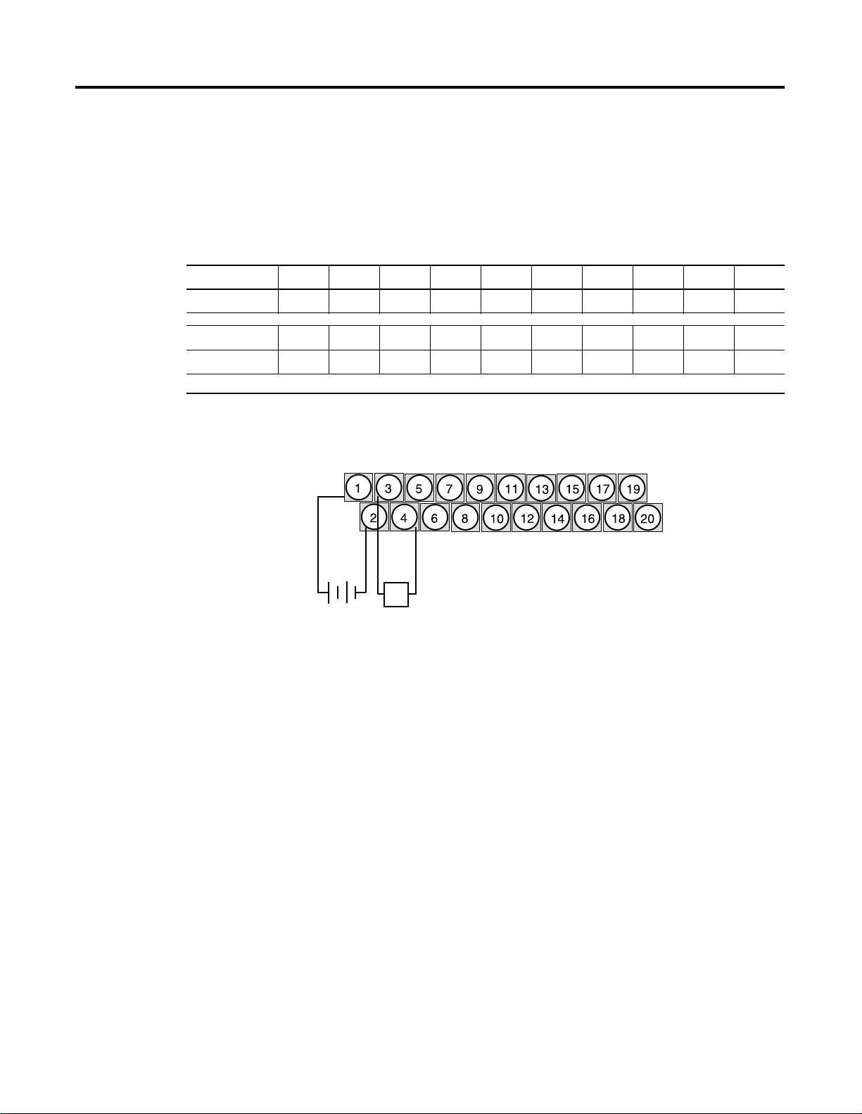
2-16 Installation and Wiring
Pin Number 12345678910
Description: +24V GND CH0 COM CH1 COM CH2 COM CH3 COM
Pin Number: 11 12 13 14 15 16 17 18 19 20
Description: NC NC NC NC NC NC NC NC NC NC
+24V = Field Power (+) 24V dc GND = Field Power (-) GND
1790D-TN4C0, 1790D-TN4V0 Analog 4 Input Base Modules Wiring
Table 2.5 lists the module pin descriptions. Figure 2.4 and Figure 2.5
show how to wire each module.
Table 2.5
1790D-TN4C0 and 1790D-TN4V0 Module Pin Descriptions
Figure 2.4
Example of Input Wiring to the 1790D-TN4C0 Module
+24V
GND
+ –
24V dc
CH0
+
COM
–
mA
Figure 2.5
Example of Input Wiring to the 1790D-TN4V0 Module
+24V
GND
+ –
24V dc
CH0
+
COM
–
V
Publication 1790-UM001A-EN-P - March 2002
Page 33
Installation and Wiring 2-17
1790D-N0C2, 1790D-N0V2 Analog 2 Output Base D-Shell Modules
Wiring
Table 2.6 lists the module pin descriptions. Figure 2.6 shows how to
wire each module.
Table 2.6
1790D-N0C2 and 1790D-N0V2 Module Pin Descriptions
Pin Number 12345678910
Description: NC NC NC NC NC NC NC NC NC CH1
Pin Number: 11 12 13 14 15 16 17 18 19 20
Description: NC CH0 NC NC NC NC +24V +24V +24V NC
Pin Number 21 22 23 24 25 26 27 28 29 30
Description: NC NC NC NC NC NC NC COM NC COM
Pin Number: 31 32 33 34 35 36 37
Description: NC NC NC NC GND GND GND
NC = No Connect +24V = Field Power (+) 24V dc GND = Field Power (-) GND
Figure 2.6
Example of Input Wiring to the 1790D-N0C2 and 1790D-N0V2 Modules
+24V
GND
+ –
24V dc
L
+ –
CH0
COM
43225
Publication 1790-UM001A-EN-P - March 2002
Page 34
2-18 Installation and Wiring
Pin Number 12345678910
Description: +24V GND CH0 COM CH1 COM NC NC NC NC
Pin Number: 11 12 13 14 15 16 17 18 19 20
Description: NC NC NC NC NC NC NC NC NC NC
+24V = Field Power (+) 24V dc GND = Field Power (-) GND
1790D-TN0C2, 1790D-TN0V2 Analog 4 Input Base Modules Wiring
Table 2.7 lists the module pin descriptions. Figure 2.7 shows how to
wire each module.
Table 2.7
1790D-TN0C2 and 1790D-TN0V2 Module Pin Descriptions
Figure 2.7
Example of Input Wiring to the 1790D-TN0C2 and 1790D-TN0V2 Modules
+24V
GND
+ – +
24V dc
CH0
COM
–
L
43226
Publication 1790-UM001A-EN-P - March 2002
Page 35

Chapter
3
Module Data, Status, and Channel
Configuration for Analog Input Modules
This chapter examines the analog input module’s data table, channel
status, and channel configuration.
Analog Input Image
The input image file represents data words and status bits. Input
words 0 through 3 hold the input data that represents the value of the
analog inputs for channels 0 through 3. These data words are valid
only when the channel is enabled and there are no errors. Input word
4 holds the status bits. Analog input data is presented as
raw/proportional.
Input words 5 and 6 contain input data for two optional discrete input
expansion modules.
1790D-N4C0/TN4C0 Configuration
Each analog current input may be configured for either the 4-20mA or
0-20mA range. This is most easily accomplished via RSNetWorx for
DeviceNet, as shown on page 3-8.
1 Publication 1790-UM001A-EN-P - March 2002
Page 36
3-2 Module Data, Status, and Channel Configuration for Analog Input Modules
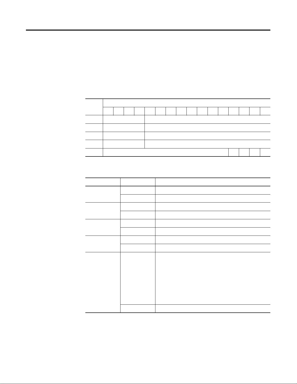
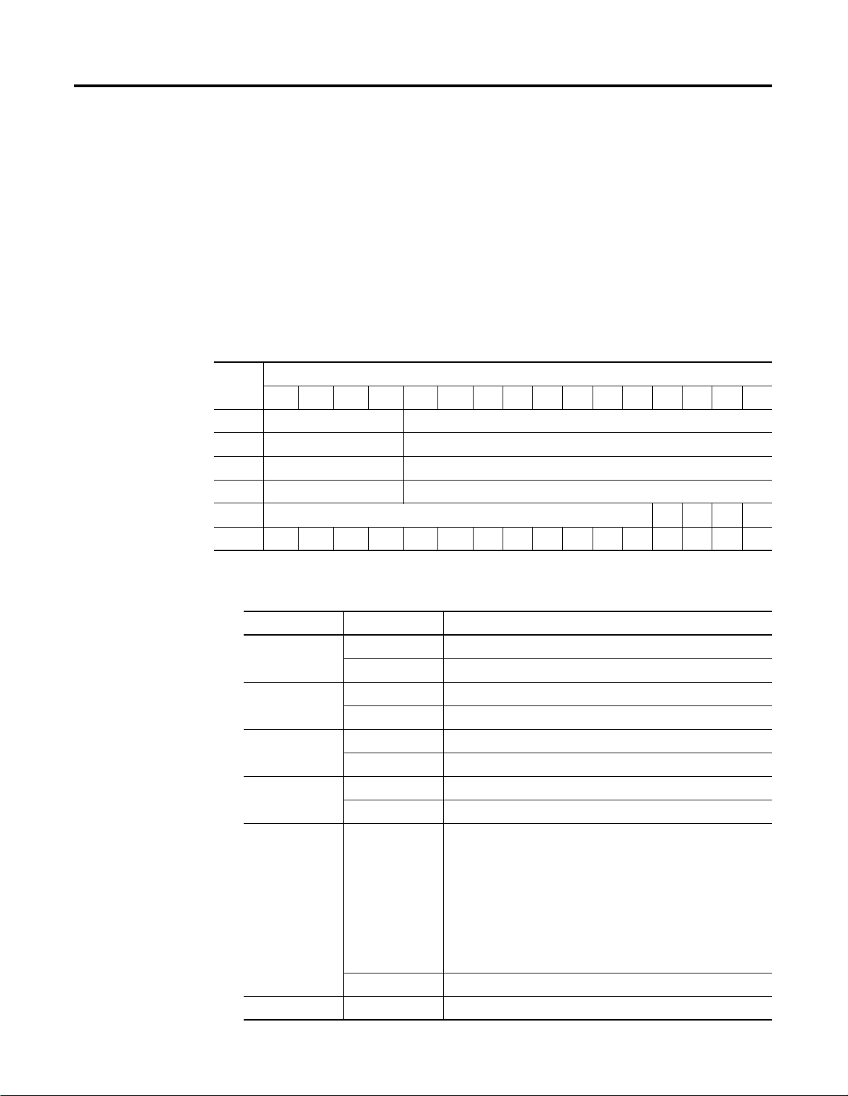
Analog Input Data File
The input data table allows you to access analog input module and
data for use in the control program, via word and bit access. The data
table structure is shown below.
1790D-N4C0/-TN4C0, 1790D-N4V0/-TN4V0 Input Data File
Word Bit Position
1514131211109876543210
0 Not Used Analog Input Data Channel 0
1 Not Used Analog Input Data Channel 1
2 Not Used Analog Input Data Channel 2
3 Not Used Analog Input Data Channel 3
4 Not Used S3 S2 S1 S0
Word/Bit Descriptions
Word Decimal Bit Description
Read Word 0 Bits 00-11 Channel 0 input data
Bits 12-15 Not used: Set to 0
Read Word 1 Bits 00-11 Channel 1 input data
Bits 12-15 Not used: Set to 0
Read Word 2 Bits 00-11 Channel 2 input data
Bits 12-15 Not used: Set to 0
Read Word 3 Bits 00-11 Channel 3 input data
Bits 12-15 Not used: Set to 0
Read Word 4 Bits 00-03 Status bits for individual channels - Bit 00 corresponds to input
channel 0, bit 01 corresponds to input channel 1 and so on.
When set (1) indicates:
• No field power
• Open wire (4-20mA current input only)
• Under range (4-20mA current input only)
• Recoverable module fault (whole channel to be set)
• Unrecoverable module fault (whole channel to be set)
Bits 04-15 Not used: Set to 0
Publication 1790-UM001A-EN-P - March 2002
Page 37

Module Data, Status, and Channel Configuration for Analog Input Modules 3-3
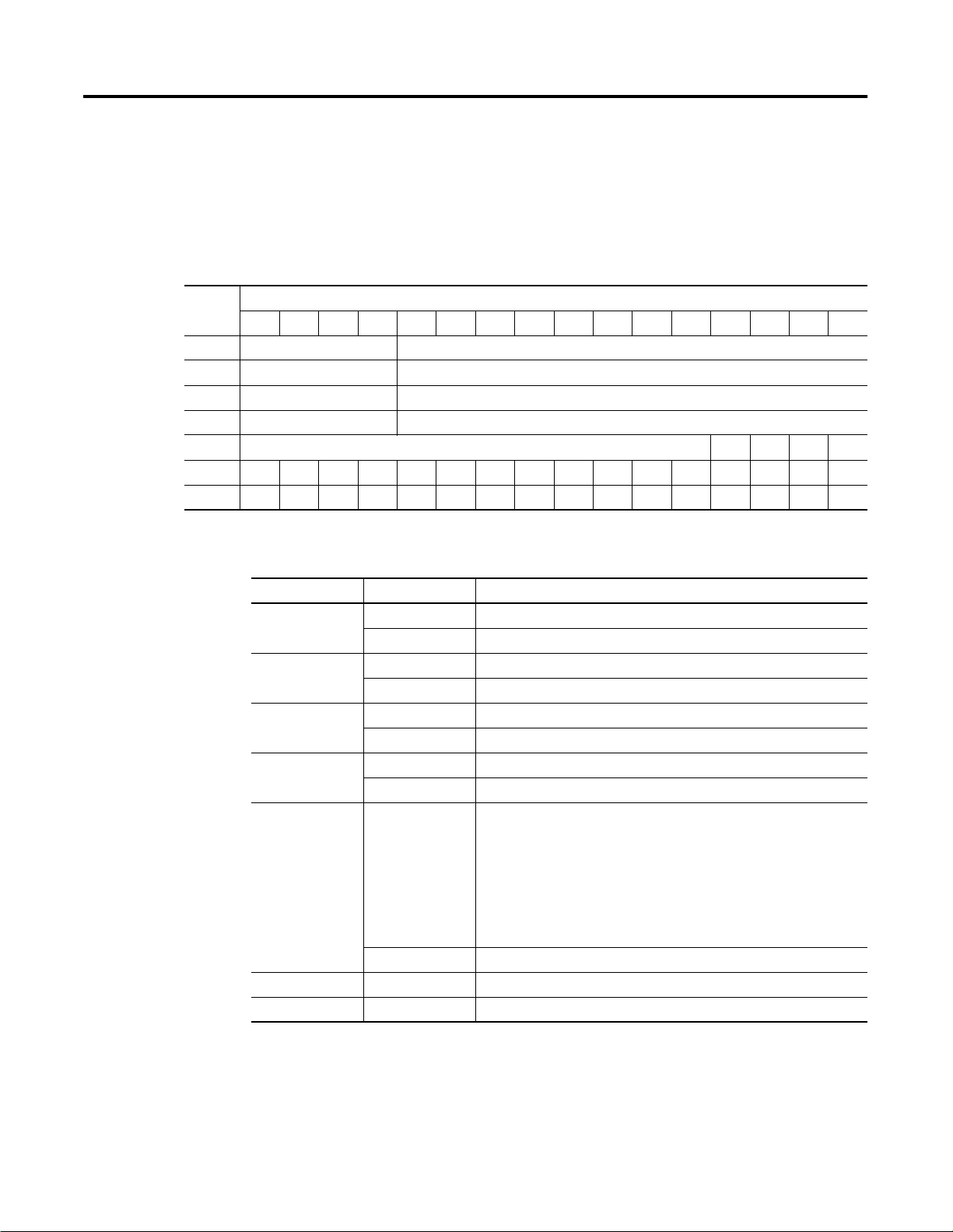
Analog Input Data File With Discrete Input Expansion Modules
The data table below shows the structure for an analog base module
with one (1) of the following 8-input modules:
• 1790-8BV8BX/-T8BV8BX
• 1790-T8A0X discrete expansion module.
1790D-N4C0/-TN4C0, 1790D-N4V0/-TN4V0 Input Data File with 8-Bit
Discrete Expansion Module
Word Bit Position
1514131211109876543210
0 Not Used Analog Input Data Channel 0
1 Not Used Analog Input Data Channel 1
2 Not Used Analog Input Data Channel 2
3 Not Used Analog Input Data Channel 3
4 Not Used S3 S2 S1 S0
5 Not Used D7 D6 D5 D4 D3 D2 D1 D0
Word/Bit Descriptions
Word Decimal Bit Description
Read Word 0 Bits 00-11 Channel 0 input data
Bits 12-15 Not used: Set to 0
Read Word 1 Bits 00-11 Channel 1 input data
Bits 12-15 Not used: Set to 0
Read Word 2 Bits 00-11 Channel 2 input data
Bits 12-15 Not used: Set to 0
Read Word 3 Bits 00-11 Channel 3 input data
Bits 12-15 Not used: Set to 0
Read Word 4 Bits 00-03 Status bits for individual channels - Bit 00 corresponds to input
channel 0, bit 01 corresponds to input channel 1 and so on.
When set (1) indicates:
• No field power
• Open wire (4-20mA current input only)
• Under range (4-20mA current input only)
• Recoverable module fault (whole channel to be set)
• Unrecoverable module fault (whole channel to be set)
Bits 04-15 Not used: Set to 0
Read Word 5 Bits 00-07 Discrete Input expansion data
Bits 08-15 Not Used
Publication 1790-UM001A-EN-P - March 2002
Page 38
3-4 Module Data, Status, and Channel Configuration for Analog Input Modules
The data table below shows the structure for an analog base module
with two (2) of the following 8-input modules:
• 1790-8BV8BX/-T8BV8BX modules,
• 1790-T8A0X discrete expansion modules
or one (1) of the following 16-input modules:
• 1790-16BV0X/-T16BV0X discrete expansion modules
1790D-N4C0/-TN4C0, 1790D-N4V0/-TN4V0 Input Data File with 16-Bit
Discrete Expansion Module(s)
Word Bit Position
1514131211109876543210
0 Not Used Analog Input Data Channel 0
1 Not Used Analog Input Data Channel 1
2 Not Used Analog Input Data Channel 2
3 Not Used Analog Input Data Channel 3
4 Not Used S3 S2 S1 S0
5 D15D14D13D12D11D10D9D8D7D6D5D4D3D2D1D0
Word/Bit Descriptions
Word Decimal Bit Description
Read Word 0 Bits 00-11 Channel 0 input data
Bits 12-15 Not used: Set to 0
Read Word 1 Bits 00-11 Channel 1 input data
Bits 12-15 Not used: Set to 0
Read Word 2 Bits 00-11 Channel 2 input data
Bits 12-15 Not used: Set to 0
Read Word 3 Bits 00-11 Channel 3 input data
Bits 12-15 Not used: Set to 0
Read Word 4 Bits 00-03 Status bits for individual channels - Bit 00 corresponds to input
channel 0, bit 01 corresponds to input channel 1 and so on.
When set (1) indicates:
• No field power
• Open wire (4-20mA current input only)
• Under range (4-20mA current input only)
• Recoverable module fault (whole channel to be set)
• Unrecoverable module fault (whole channel to be set)
Bits 04-15 Not used: Set to 0
Read Word 5 Bits 00-15 Discrete Input expansion data
Publication 1790-UM001A-EN-P - March 2002
Page 39

Module Data, Status, and Channel Configuration for Analog Input Modules 3-5
The data table below shows the structure for an analog base module
with one (1) of the following 16-input modules:
• 1790-16BV0X/-T16BV0X discrete expansion module
and one (1) of the following 8-input modules:
• 1790-8BV8BX/-T8BV8BX discrete expansion module
• 1790-8BV8VX/T8BVX discrete expansion module
• 1790-T8A0X discrete expansion module
1790D-N4C0/-TN4C0, 1790D-N4V0/-TN4V0 Input Data File with 24-Bit
Discrete Expansion Modules
Word Bit Position
1514131211109876543210
0 Not Used Analog Input Data Channel 0
1 Not Used Analog Input Data Channel 1
2 Not Used Analog Input Data Channel 2
3 Not Used Analog Input Data Channel 3
4 Not Used S3 S2 S1 S0
5 D15D14D13D12D11D10D9D8D7D6D5D4D3D2D1D0
6 Not Used D23 D22 D21 D20 D19 D18 D17 D16
Word/Bit Descriptions
Word Decimal Bit Description
Read Word 0 Bits 00-11 Channel 0 input data
Bits 12-15 Not used: Set to 0
Read Word 1 Bits 00-11 Channel 1 input data
Bits 12-15 Not used: Set to 0
Read Word 2 Bits 00-11 Channel 2 input data
Bits 12-15 Not used: Set to 0
Read Word 3 Bits 00-11 Channel 3 input data
Bits 12-15 Not used: Set to 0
Read Word 4 Bits 00-03 Status bits for individual channels - Bit 00 corresponds to input channel 0,
Bits 04-15 Not used: Set to 0
Read Word 5 Bits 00-15 First discrete Input expansion data
Read Word 6 Bits 00-07 Second discrete Input expansion data
Bits 08-15 Not Used
bit 01 corresponds to input channel 1 and so on. When set (1) indicates:
• No field power
• Open wire (4-20mA current input only)
• Under range (4-20mA current input only)
• Recoverable module fault (whole channel to be set)
• Unrecoverable module fault (whole channel to be set)
Publication 1790-UM001A-EN-P - March 2002
Page 40
3-6 Module Data, Status, and Channel Configuration for Analog Input Modules
The data table below shows the structure for an analog base module
with two (2) 16-input 1790-16BV0X/-T16BV0X discrete expansion
modules.
1790D-N4C0/-TN4C0, 1790D-N4V0/-TN4V0 Input Data File with 32-Bit
Discrete Expansion Modules
Word Bit Position
1514131211109876543210
0 Not Used Analog Input Data Channel 0
1 Not Used Analog Input Data Channel 1
2 Not Used Analog Input Data Channel 2
3 Not Used Analog Input Data Channel 3
4 Not Used S3 S2 S1 S0
5 D15D14D13D12D11D10D9D8D7D6D5D4D3D2D1D0
6 D31 D30 D29 D28 D27 D26 D25 D24 D23 D22 D21 D20 D19 D18 D17 D16
Word/Bit Descriptions
Word Decimal Bit Description
Read Word 0 Bits 00-11 Channel 0 input data
Bits 12-15 Not used: Set to 0
Read Word 1 Bits 00-11 Channel 1 input data
Bits 12-15 Not used: Set to 0
Read Word 2 Bits 00-11 Channel 2 input data
Bits 12-15 Not used: Set to 0
Read Word 3 Bits 00-11 Channel 3 input data
Bits 12-15 Not used: Set to 0
Read Word 4 Bits 00-03 Status bits for individual channels - Bit 00 corresponds to input
channel 0, bit 01 corresponds to input channel 1 and so on. When
set (1) indicates:
No field power
Open wire (4-20mA current input only)
Under range (4-20mA current input only)
Recoverable module fault (whole channel to be set)
Unrecoverable module fault (whole channel to be set)
Bits 04-15 Not used: Set to 0
Read Word 5 Bits 00-15 First discrete Input expansion data
Read Word 6 Bits 00-15 Second discrete Input expansion data
Publication 1790-UM001A-EN-P - March 2002
Page 41

Module Data, Status, and Channel Configuration for Analog Input Modules 3-7
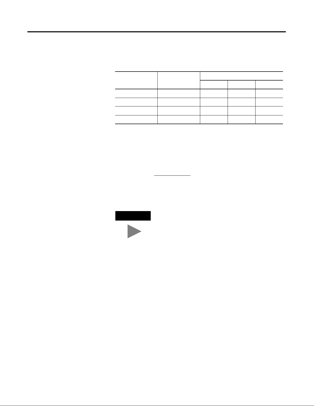
Analog Input Data Format
Module: Input Full Scale
1790D-N4V0/-TN4V0 0-10V dc 0000-0FFF 0-4095 2.44mV
1790D-N4C0/-TN4C0 4-20mA 0000-0FFF 0-4095 3.90µA
Configuring Analog Input Module
Analog input data is presented as raw/proportional. The full 12-bit
resolution is used over the entire span of the input full scale range, as
shown in Table 3.1.
Table 3.1
HEX Data Range: Decimal Data
Range:
0-20mA 0000-0FFF 0-4095 4.88
Configuring CompactBlock LDX modules is as easy as POINT and
click. RSNetWorx for DeviceNet™ allows you to simply identify the
network and configure the I/O modules with easy-to-use Electronic
Data Sheets (EDS). Just POINT to the field and click on your selection.
To obtain EDS files for use in configuration, go to:
http://www.ab.com/networks/eds.
Range:
Input Resolution:
µA
EDS files for blocks with matching catalog numbers (for D-Shell and
terminal block versions) are the same. Thus on the website or in
RSNetWorx for DeviceNet, there may be only one catalog number
listed for both versions.
When using 3rd-party configuration software, simply load the EDS
files into the software and follow the vendor’s instructions.
Publication 1790-UM001A-EN-P - March 2002
Page 42

3-8 Module Data, Status, and Channel Configuration for Analog Input Modules
Configuring Analog Modules With RSNetWorx
A. Use the + signs to open the
following path:
DeviceNet
ÕVendor
Õ Rockwell Automation -
Allen-Bradley
Õ Rockwell Automation
miscellaneous
B. Double-click on the module.
To configure analog modules, proceed as described in the steps
below:
1. Open RSNetWorx for DeviceNet.
2. Add an analog input module (e.g. 1790D-N4C0) to the network,
as shown below..
It appears on the network.
3. Double-click on the module icon on the DeviceNet network. If
you are online, upload the configuration and existing module
parameters are shown. A page similar to the one below appears.
Publication 1790-UM001A-EN-P - March 2002
Page 43

Module Data, Status, and Channel Configuration for Analog Input Modules 3-9
4. Click on the Module Configuration tab. Analog input modules
have a configuration screen similar to the screen shown below
for the 1790D-N4C0 module.
A. Click on the catalog number. B. Click on Properties.
C. Use the pull-down menu to
change range selection.
D. Click on OK after making all
configuration changes.
Use the Parameters tab to change module configuration. For example,
the screen below shows how to change an AMP range selection.
Publication 1790-UM001A-EN-P - March 2002
Page 44

3-10 Module Data, Status, and Channel Configuration for Analog Input Modules
The screen returns to "Module Configuration".
A. Click on Download to save
your configuration.
B. Click on OK after making all
configuration changes.
Publication 1790-UM001A-EN-P - March 2002
Page 45

Chapter
4
Module Data, Status, and Channel
Configuration for Analog Output Modules
This chapter examines the analog output module’s output data file
and configuration.
Analog Output Image
The output image file represents data words. Output words 0 and 1
hold the output data that represents the value of the analog outputs
for channels 0 and 1. Analog output data is presented as
raw/proportional.
Output words 2 and 3 contain output data for two optional discrete
output expansion modules.
1 Publication 1790-UM001A-EN-P - March 2002
Page 46

4-2 Module Data, Status, and Channel Configuration for Analog Output Modules
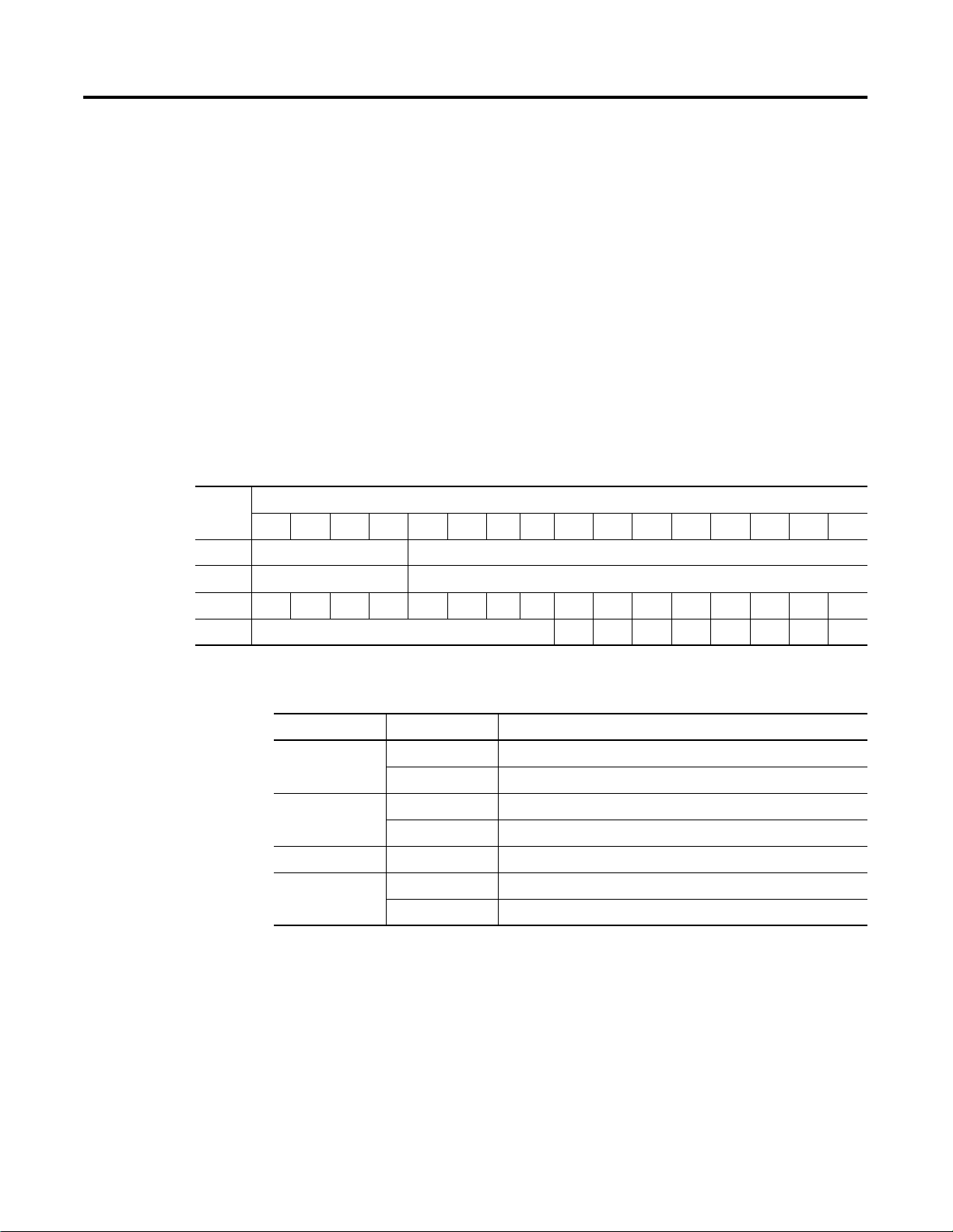
Analog Output Data File
The structure of the output data file is shown below.
1790D-N0C2/-TN0C2, 1790D-N0V2/-TN0V2 Output Data File
Word Bit Position
1514131211109876543210
0 Not Used Analog Output Data Channel 0
1 Not Used Analog Output Data Channel 1
Word/Bit Descriptions
Word Decimal Bit Description
Write Word 0 Bits 00-11 Channel 0 output data
Bits 12-15 Not used: Set to 0
Write Word 1 Bits 00-11 Channel 1 output data
Bits 12-15 Not used: Set to 0
Publication 1790-UM001A-EN-P - March 2002
Page 47

Module Data, Status, and Channel Configuration for Analog Output Modules 4-3
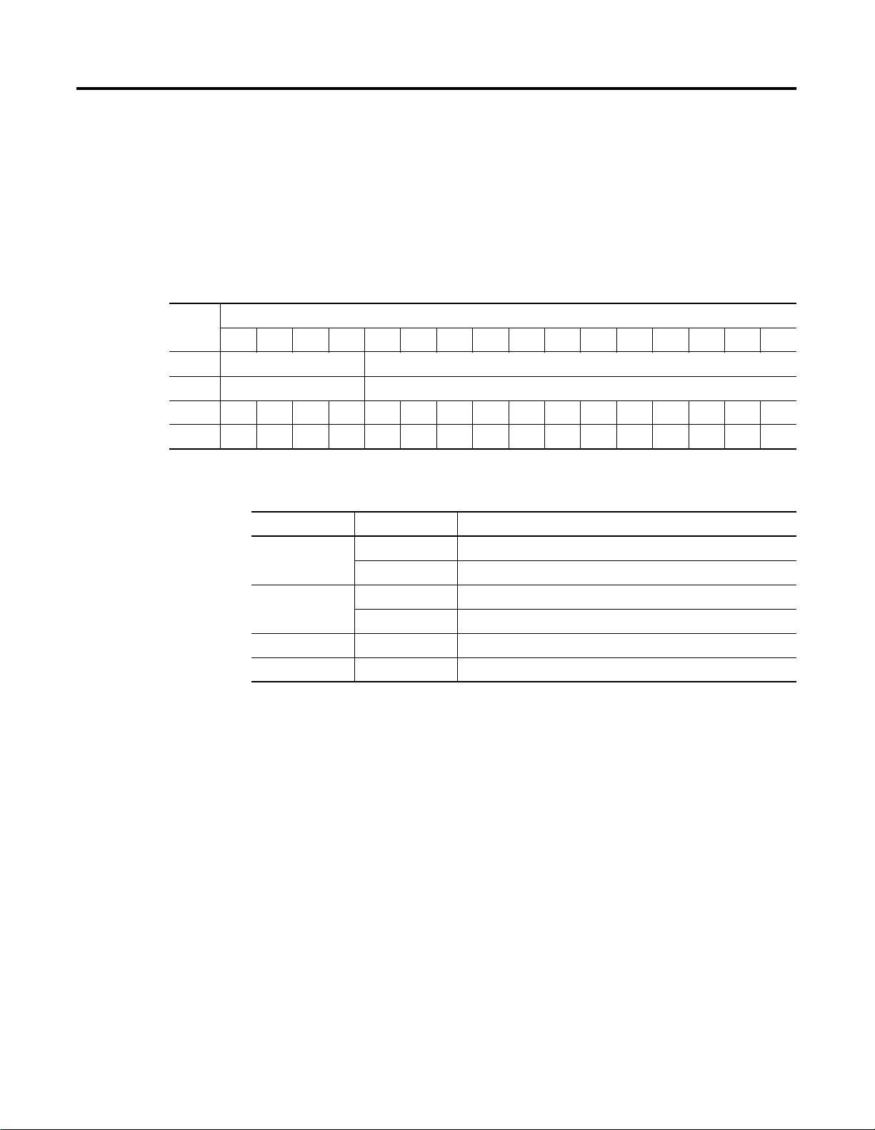
Analog Output Data File With Discrete Output Expansion Modules
The data table below shows the structure for an analog base module
with one of the following 8-output modules:
• 1790-8BV8BX/-T8BV8BX discrete expansion module
• 1790-8BV8VX/-T8BV8VX discrete expansion module
• 1790-TOA8X discrete expansion module
• 1790-T0W8X discrete expansion module.
1790D-N0C2/-TN0C2, 1790D-N0V2/-TN0V2 Output Data File with 8-Bit
Discrete Expansion Module
Word Bit Position
1514131211109876543210
0 Not Used Analog Output Data Channel 0
1 Not Used Analog Output Data Channel 1
2 Not Used
D7 D6 D5 D4 D3 D2 D1 D0
Word/Bit Descriptions
Word Decimal Bit Description
Write Word 0 Bits 00-11 Channel 0 output data
Bits 12-15 Not used: Set to 0
Write Word 1 Bits 00-11 Channel 1 output data
Bits 12-15 Not used: Set to 0
Write Word 2 Bits 00-07 Discrete output expansion data
Bits 08-15 Not used: Set to 0
Publication 1790-UM001A-EN-P - March 2002
Page 48

4-4 Module Data, Status, and Channel Configuration for Analog Output Modules
The data table below shows the structure for an analog base module
with one (1) of the following 16-output modules:
• 1790-OB16X/-TOB16X discrete expansion module
• 1790-OV16X/-TOV16X discrete expansion module
or two (2) of the following 8-output modules:
• 1790-8BV8BX/-T8BV8BX discrete expansion modules
• 1790-8BV8VX/-T8BV8VX discrete expansion modules
• 1790-TOA8X discrete expansion modules
• 1790-TOW8X discrete expansion modules
1790D-N0C2/-TN0C2, 1790D-N0V2/-TN0V2 Output Data File with 16-Bit
Discrete Expansion Module(s)
Word Bit Position
1514131211109876543210
0 Not Used Analog Output Data Channel 0
1 Not Used Analog Output Data Channel 1
2 D15D14D13D12D11D10D9D8D7D6D5D4D3D2D1D0
Word/Bit Descriptions
Word Decimal Bit Description
Write Word 0 Bits 00-11 Channel 0 output data
Bits 12-15 Not used: Set to 0
Write Word 1 Bits 00-11 Channel 1 output data
Bits 12-15 Not used: Set to 0
Write Word 2 Bits 00-15 Discrete output expansion data
Publication 1790-UM001A-EN-P - March 2002
Page 49
Module Data, Status, and Channel Configuration for Analog Output Modules 4-5
The data table below shows the structure for an analog base module
with one (1) of the following 16-output modules:
• 1790-OB16X/-TOB16X discrete expansion module
• 1790-OV16X/-TOV16X discrete expansion module
and with one (1) of the following 8-input modules
• 1790-8BV8BX/-T8BV8BX discrete expansion module
• 1790-8BV8VX/T8BV8VX discrete expansion module
• 1790-TOA8X discrete expansion module
• 1790-TOW8X discrete expansion module
1790D-N4C0/-TN4C0, 1790D-N4V0/-TN4V0 Output Data File with 24-Bit
Discrete Expansion Modules
Word Bit Position
1514131211109876543210
0 Not Used Analog Output Data Channel 0
1 Not Used Analog Output Data Channel 1
2 D15D14D13D12D11D10D9D8D7D6D5D4D3D2D1D0
3 Not Used D23 D22 D21 D20 D19 D18 D17 D16
Word/Bit Descriptions
Word Decimal Bit Description
Write Word 0 Bits 00-11 Channel 0 output data
Bits 12-15 Not used: Set to 0
Write Word 1 Bits 00-11 Channel 1 output data
Bits 12-15 Not used: Set to 0
Write Word 2 Bits 00-15 First discrete output expansion data
Write Word 3 Bits 00-07 Second discrete output expansion data
Bits 08-15 Not used: Set to 0
Publication 1790-UM001A-EN-P - March 2002
Page 50
4-6 Module Data, Status, and Channel Configuration for Analog Output Modules
The data table below shows the structure for an analog base module
with two (2) of the following 16-output modules:
• 1790-OB16X/-TOB16X discrete expansion modules
• 1790-OV16X/-TOV16X discrete expansion modules
1790D-N4C0/-TN4C0, 1790D-N4V0/-TN4V0 Output Data File with 32-Bit
Discrete Expansion Modules
Word Bit Position
1514131211109876543210
0 Not Used Analog Output Data Channel 0
1 Not Used Analog Output Data Channel 1
2 D15D14D13D12D11D10D9D8D7D6D5D4D3D2D1D0
3 D31 D30 D29 D28 D27 D26 D25 D24 D23 D22 D21 D20 D19 D18 D17 D16
Word/Bit Descriptions
Word Decimal Bit Description
Write Word 0 Bits 00-11 Channel 0 output data
Bits 12-15 Not used: Set to 0
Write Word 1 Bits 00-11 Channel 1 output data
Bits 12-15 Not used: Set to 0
Write Word 2 Bits 00-15 First discrete output expansion data
Write Word 3 Bits 00-15 Second discrete output expansion data
Publication 1790-UM001A-EN-P - March 2002
Page 51
Module Data, Status, and Channel Configuration for Analog Output Modules 4-7
Analog Output Data Format
Module: Output Full Scale
1790D-NOV2/-TNOV2 0-10V dc 0000-0FFF 0-4095 2.44mV
1790D-N0C2/-TNOC2 0-20mA 0000-0FFF 0-4095 4.88µA
Output Fault and Idle States
Analog output data is presented as raw/proportional. The full 12-bit
resolution is used over the entire span of the output full scale range,
as shown in Table 4.1.
Table 4.1
Range:
HEX Data Range: Decimal Data
Range:
Output Resolution:
Analog output fault (communication failure) and idle (processor in
program mode) state can be defined for each output. Both fault state
and idle state can have the behavior defined in Table 4.2 for each
output.
Table 4.2
Behavior: 1790D-N0C2/-TN0C2: 1790D-N0V2/-TN0V2:
Go to low clamp 0mA 0V dc
Go to high clamp 20mA 10V dc
Go to fault/idle value User configurable User configurable
Hold last state Hold last value Hold last value
The user-specified value is entered in raw/proportional notation. For
example:
• 0 is the low clamp. This value equals 0mA or oV dc.
• 4095 is the high clamp. This value equals 20mA or 10V dc.
• Values between 0 and 4095 denote proportional values. 2048
equals 10mA or 5V dc.
The values in the output data file are retained. Once a fault or idle
condition is cleared, the retained output values are sent to the analog
output channels.
Publication 1790-UM001A-EN-P - March 2002
Page 52
4-8 Module Data, Status, and Channel Configuration for Analog Output Modules
Configuring Analog Output Module
Configuring CompactBlock LDX modules is as easy as POINT and
click. RSNetWorx allows you to simply identify the network and
configure the I/O modules with easy-to-use Electronic Data Sheets
(EDS). Just POINT to the field and click on your selection.
To obtain EDS files for use in configuration, go to:
http://www.ab.com/networks/eds.
EDS files for blocks with matching catalog numbers (for D-Shell and
terminal block versions) are the same. Thus on the website or in
RSNetWorx for DeviceNet, there may be only one catalog number
listed for both versions.
When using 3rd-party configuration software, simply load the EDS
files into the software and follow the vendor’s instructions.
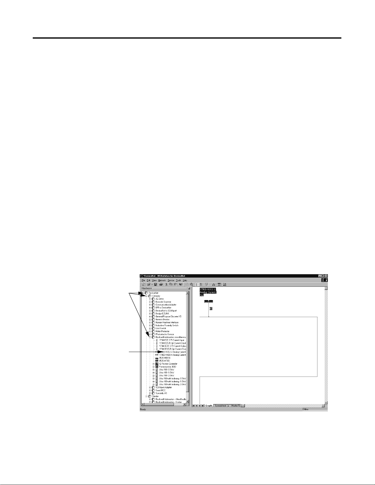
Using RSNetWorx for DeviceNet
To configure analog input modules, follow these steps:
A. Use the + signs to open the
following path:
DeviceNet
ÕRocwell Automation -
Allen-Bradley
Õ Rockwell Automation -
miscellaneous
B. Double-click on the module.
It appears on the network.
1. Open RSNetWorx for DeviceNet.
2. Add an analog output module (e.g. 1790D-N0C2) to the
network, as shown below..
Publication 1790-UM001A-EN-P - March 2002
If your network is running, you can also click on the Browse
button to see what modules are on the network.
Page 53
Module Data, Status, and Channel Configuration for Analog Output Modules 4-9
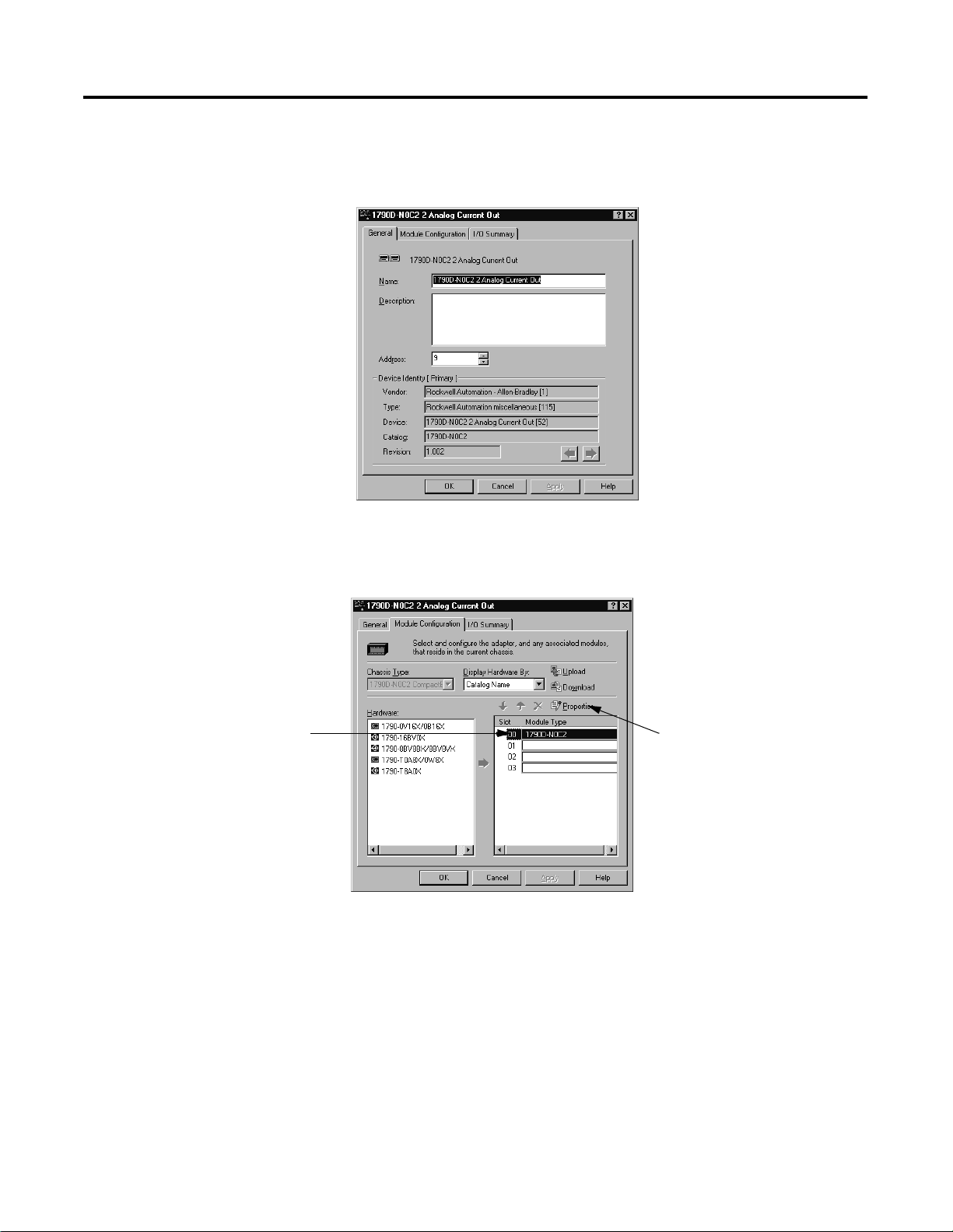
3. Double-click on the module icon on the DeviceNet network. If
you are online, upload the configuration and existing module
parameters are shown. A page similar to the one below appears.
4. Click on the Module Configuration tab. Analog input modules
have a configuration screen similar to the screen shown below
for the 1790D-N0C2 module.
A. Click on the catalog number. B. Click on Properties.
Publication 1790-UM001A-EN-P - March 2002
Page 54
4-10 Module Data, Status, and Channel Configuration for Analog Output Modules
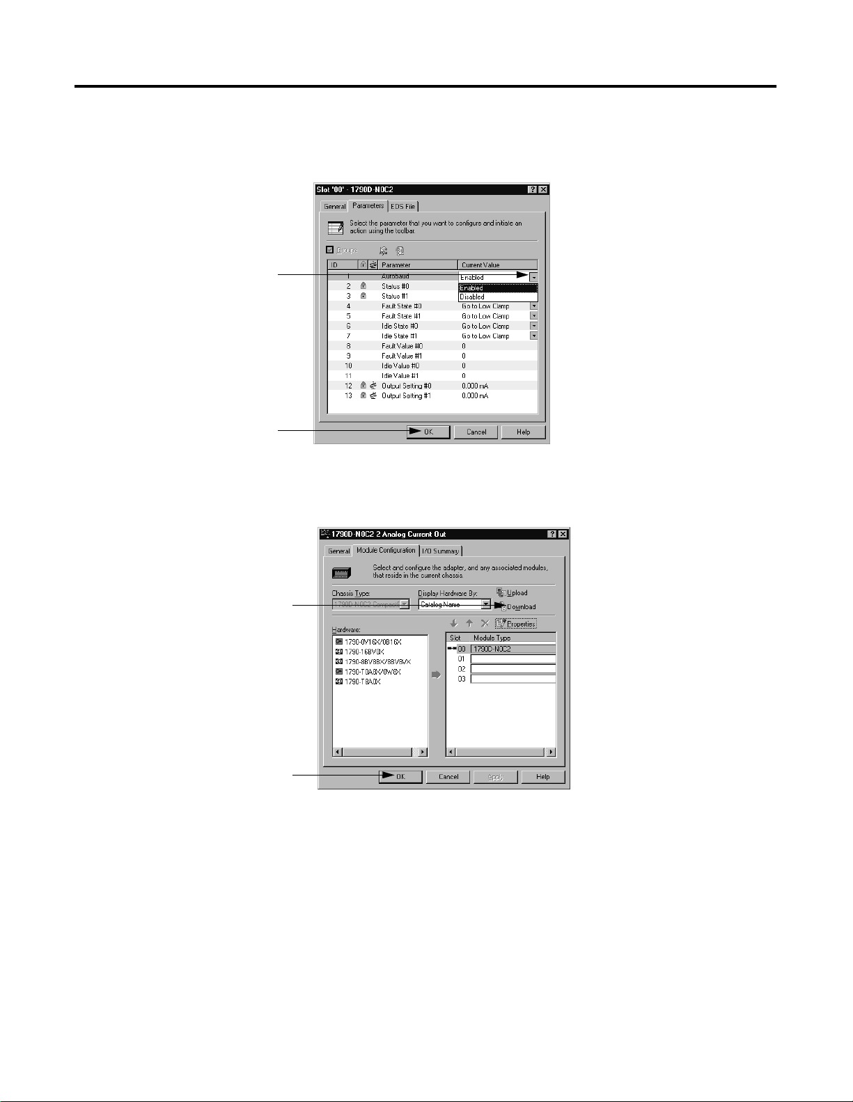
Use the Parameters tab to change module configuration. For example,
the screen below shows how to change the Autobaud selection.
C. Use the pull-down menu to
change range selection.
D. Click on OK after making all
configuration changes.
A. Click on Download to save
your configuration.
B. Click on OK after making all
configuration changes.
The screen returns to "Module Configuration".
Publication 1790-UM001A-EN-P - March 2002
Page 55

Chapter
5
Module Diagnostics and Troubleshooting
This chapter describes troubleshooting the analog input and output
modules. This chapter contains information on:
• safety considerations when troubleshooting
• module vs. channel operation
• the module’s diagnostic features
Safety Considerations
Safety considerations are an important element of proper
troubleshooting procedures. Actively thinking about the safety of
yourself and others, as well as the condition of your equipment, is of
primary importance.
The following sections describe several safety concerns you should be
aware of when troubleshooting your control system.
ATTENTION
!
Never reach into a machine to actuate a switch
because unexpected motion can occur and cause
injury.
Remove all electrical power at the main power
disconnect switches before checking electrical
connections or inputs/outputs causing machine
motion.
Indicator Lights
When the green MOD and NET LED indicator lights on the analog
module are illuminated, it indicates that power is applied to the
module, and the module is communicating on the network.
1 Publication 1790-UM001A-EN-P - March 2002
Page 56

5-2 Module Diagnostics and Troubleshooting
Activating Devices When Troubleshooting
When troubleshooting, never reach into the machine to actuate a
device. Unexpected machine motion could occur.
Stand Clear of the Machine
When troubleshooting any system problem, have all personnel remain
clear of the machine. The problem could be intermittent, and sudden
unexpected machine motion could occur. Have someone ready to
operate an emergency stop switch in case it becomes necessary to
shut off power to the machine.
Program Alteration
There are several possible causes of alteration to the user program,
including extreme environmental conditions, Electromagnetic
Interference (EMI), improper grounding, improper wiring
connections, and unauthorized tampering. If you suspect a program
has been altered, check it against a previously saved program on an
EEPROM or UVPROM memory module.
Safety Circuits
Circuits installed on the machine for safety reasons, like over-travel
limit switches, stop push buttons, and interlocks, should always be
hard-wired to the master control relay. These devices must be wired
in series so that when any one device opens, the master control relay
is de-energized, thereby removing power to the machine. Never alter
these circuits to defeat their function. Serious injury or machine
damage could result.
Publication 1790-UM001A-EN-P - March 2002
Page 57
Module Diagnostics and Troubleshooting 5-3
Module Operation vs. Channel Operation
Power-up Diagnostics
The module performs operations at two levels:
• module level - power-up, configuration, and communication
with a controller
• channel level - data conversion and over- or under-range
detection
Internal diagnostics are performed at both levels of operation. When
detected, module error conditions are indicated by the module status
and individual channel LED lights.
Module Status
At module power-up, a series of internal diagnostic tests are
performed. These diagnostic tests must be successfully completed.
Table 5.1 shows module status LED indicator operation.
Table 5.1
LED indicator: Status: Description:
Module status Solid red Unrecoverable fault in base unit
Flashing red Recoverable fault
Solid green Normal operation
Flashing green Stand by
Off No power
Network Status
The network status LED indicator shows the condition of the
DeviceNet connection. Table 5.2 shows network status LED
indicator operation.
Table 5.2
LED indicator: Status: Description:
Network status Solid red Unrecoverable communication fault
Flashing red Recoverable communication fault
Solid green Communication path complete
Flashing green Communication path incomplete
Off Device is not online or not powered
Publication 1790-UM001A-EN-P - March 2002
Page 58

5-4 Module Diagnostics and Troubleshooting
Channel Diagnostics
When an input or output module channel is enabled, the module
performs a diagnostic check to see that the channel has been properly
configured. In addition, the module checks each channel on every
scan for configuration errors, under-range, open-circuit (input module
in 4 to 20 mA range only).
Out-of-Range Detection (Input
An out-of-range low test is performed on all channels configured for
4-20mA inputs. Whenever an out-of-range low condition occurs, the
status bit for that channel is set in input data word 4.
Open-Circuit Detection (Input
The module performs an open-circuit test on all channels configured
for 4 to 20 mA inputs. Whenever an open-circuit condition occurs, the
status bit for that channel is set in input data word 4.
Modul
es Only)
Module On
ly)
Possible causes of an open circuit include:
• the sensing device may be broken
• a wire may be loose or cut
• the sensing device may not be installed on the configured
channel
Publication 1790-UM001A-EN-P - March 2002
Page 59

Module Diagnostics and Troubleshooting 5-5
Analog Input Module Error
Analog input module errors are expressed on a channel bases in input
read word 4. The structure of the status data is shown below.
Definition Table
Table 5.3
Word Bit Position
1514131211109876543210
4 Not used S3 S2 S1 S0
Word/Bit Descriptions
Word Decimal Bit Description
Read Word 4 Bits 00-03 Status bits for individual channels - Bit 00 corresponds to input
channel 0, bit 01 corresponds to input channel 1 and so on.
When set (1) indicates:
• No field power
• Open wire (4-20mA current input only)
• Under range (4-20mA current input only)
• Recoverable module fault (whole channel to be set)
• Unrecoverable module fault (whole channel to be set)
Bits 04-15 Not used: Set to 0
Module Errors
Table 5.4 lists possible errors that cause the analog input module
status bits to be set.
Table 5.4
Status Bit Table 1790D-N4CO/-TN4CO, 1790D-N4VO/-TN4VO
Range
Setting
4-20mA <4mA
0-20mA <0mA
0-10V dc <0V dc
Underrange In Range Overrange Open
Set
Not set
Not set
Not set >20mA
Not set
Not set >20mA
Not set
Not set >10V
Not set
Short
Circuit
Set Set Set
Not set Not set Set
Not set Not set Set
Circuit
No Field
Power
Publication 1790-UM001A-EN-P - March 2002
Page 60

5-6 Module Diagnostics and Troubleshooting
Channel LED Indicator Operation
Individual channel LED indicator operation is shown in the following
tables.
Analog Input Modules
1790D-TN4V0 1790D-TN4C0
Status: Description: Status: Description:
Flashing
Green/Red
Off Off line Off Off line
Red On line and no field
Red DeviceNet connection
Green Field power and open
Green Field power and valid
Green Input over range Green Input over range
Green Input under range Flashing Red
Power up Flashing
Green/Red
Red On line and no field
power
Red DeviceNet connection
and no field power
Flashing Red
wire
Green Field power and valid
input
Power up
power
and no field power
(1)
Field power and open
wire (4-20mA range
(2)
only)
input
1
Input under range
<3mA (4-20ma range
2
only)
Flashing Red Recoverable fault Flashing Red Recoverable fault
(1)
Green for 0-20mA range.
(2)
Can be determined from the data table.
Publication 1790-UM001A-EN-P - March 2002
Page 61

Module Diagnostics and Troubleshooting 5-7
Analog Output Modules
1790D-TN0V2 1790D-TN0C2
Status: Description: Status: Description:
Contacting Rockwell Automation
Flashing
Green/Red
Off Off line Off Off line
Off On line and no field
Green DeviceNet connection
Green Field power and open
Green Field power and valid
Flashing Red Field power and
Flashing Green Output idle Flashing Green Output idle
Flashing Red Recoverable fault Flashing Red Recoverable fault
Power up Flashing
Green/Red
Off On line and no field
power
Green DeviceNet connection
and no field power
Green Field power and open
wire
Green Field power and valid
output
Flashing Red Field power and
output out of range
Power up
power
and no field power
wire
output
output out of range
If you need to contact Rockwell Automation for assistance, please
have the following information available when you call:
• a clear statement of the problem, including a description of what
the system is actually doing. Note the LED state; also note input
and output image words for the module.
• a list of remedies you have already tried
• processor type and firmware number (See the label on the
processor.)
• hardware types in the system, including all I/O modules
• fault code if the processor is faulted
Publication 1790-UM001A-EN-P - March 2002
Page 62

5-8 Module Diagnostics and Troubleshooting
Notes:
Publication 1790-UM001A-EN-P - March 2002
Page 63

Appendix
A
Specifications
DeviceNet Analog Base Terminal Block
The following table contains specifications that are common to all of
the blocks in this document. Individual base block specifications are
detailed after this table.
Environmental Specifications
Operating
Temperature
0 to 55°C (32 to 131°F)
IEC 60068-2-1 (Test Ad, Operating Cold),
IEC 60068-2-2 (Test Bd, Operating Dry Heat),
IEC 60068-2-14 (Test Nb, Operating Thermal Shock)
Storage Temperature -40 to 85°C (-40 to 185°F)
IEC 60068-2-1 (Test Ab, Un-packaged Non-operating Cold),
IEC 60068-2-2 (Test Bb, Un-packaged Non-operating Dry Heat),
IEC 60068-2-14 (Test Na, Un-packaged Non-operating Thermal
Shock)
Relative Humidity 5-90% non-condensing
IEC 60068-2-30 (Test Db, Un-packaged Non-operating)
Operating Altitude 2000m
Vibration IEC60068-2-6 (Test Fc, Operating):
2g @ 10-500Hz
Shock
Operating
Non-operating
Emissions CISPR 11:
ESD Immunity IEC 61000-4-2:
Radiated RF Immunity IEC 61000-4-3:
EFT/B Immunity IEC 61000-4-4:
Surge Transient
Immunity
IEC60068-2-27 (Test Ea, Unpackaged Shock):
10g
30g
Group 1, Class A
8kV air discharges
10V/m with 1kHz sine-wave 80%AM from 80MHz to 1000MHz
10V/m with 200Hz 50% Pulse 100%AM @ 900Mhz
+
1kV @ 5kHz on power ports
+2kV @ 5kHz on signal ports
2kV @ 5kHz on communications ports
+
IEC 61000-4-5:
1kV line-line(DM) and +2kV line-earth(CM) on power ports
+
1kV line-line(DM) and +2kV line-earth(CM) on signal ports
+
+
2kV line-earth(CM) on shielded ports
Conducted RF
Immunity
1 Publication 1790-UM001A-EN-P - March 2002
IEC 61000-4-6:
10Vrms with 1kHz sine-wave 80%AM from 150kHzto 80MHz
Page 64

A-2 Specifications
Environmental Specifications (continued)
Enclosure Type Rating None (open style)
Mounting DIN rail or screw
Dimensions 52x104x42mm (2.03x4.07x1.64in)
Weight 0.3lb (0.1kg)
DeviceNet Specifications
Network protocol I/O Slave messaging:
- Poll command
- Bit Strobe command
- Cyclic command
- COS command
Network length 500 meters maximum @ 125Kbps
100 meters maximum @ 500Kbps
Indicators 1 red/green module status
1 red/green network status
Number of nodes 64 maximum - rotary switch type node address setting
Communication rate 125Kbps, 250Kbps, 500Kbps - auto baud rate selection
Isolation Type test 1250Vac rms for 60 seconds between field power
and DeviceNet (I/O to logic)
Wiring Refer to publication DN-6.7.2
General Specifications
Wiring Category
Product Certifications
(when product or
packaging is marked)
(1)
2
c-UL-us UL Listed for Class I, Division 2 Group A,B,C,D
Hazardous Locations, certified for U.S. and Canada
(2)
CE
European Union 89/336/EEC EMC Directive,
compliant with:
EN 50081-2; Industrial Emissions
EN 50082-2; Industrial Immunity
EN61326; Meas./Control/Lab.,
Industrial Requirements
EN 61000-6-2; Industrial Immunity
2
C-Tick
Australian Radiocommunications Act,
compliant with:
AS/NZS 2064; Industrial Emissions
ODVA ODVA conformance tested to ODVA
DeviceNet specifications
(1)
Use this conductor category information for planning conductor routing as described in the system level
installation manual. Refer to publication 1770-4.1 “Industrial Automation Wiring and Grounding
Guidelines”.
(2)
See the Product Certification link at www.ab.com for Declarations of Conformity, Certificates, and other
certification details.
Publication 1790-UM001A-EN-P - March 2002
Page 65

4-Channel Analog Current Input Module
1790D-TN4C0
Inputs per module 4 channel single-ended, non-isolated
Input Current
(software
configurable)
Resolution 12 bits-unipolar
Converted Data Binary data
Conversion Time 10ms/channel
Overall accuracy 0.2% Full scale @0°-55°C
Calibration None required
Input Impedance 249
4-20mA (default)
0-20mA
1/4096 maximum
3.90µA/bit (4-20mA)
4.88µA/bit (0-20mA)
0000 to 0fff (max scale)
Ω
Specifications A-3
Insulation Resistance 20MΩ minimum @ 250V dc (between insulated circuits)
General Specifications
DeviceNet Power Supply voltage - 24V dc nominal
Voltage range - 11-28.8V dc
Power dissipation - 1.2W maximum @ 28.8V dc
Field Power Supply Voltage - 24Vdc nominal
Voltage Range - 21.6-26.4V dc (+
Power Dissipation - 1.5W maximum @26.4V dc
Isolation I/O to logic: photocoupler isolation
Isolation voltage: Type Test 1250V ac rms for 60 seconds
DeviceNet to logic: non-isolated
Field power: non-isolated
Indicators 4 red/green I/O status
Wiring Terminal block connector
Screw torque: 7 inch-pounds maximum
IMPORTANT: This analog base module can accommodate a maximum of two discrete
expansion modules.
10%)
Publication 1790-UM001A-EN-P - March 2002
Page 66

A-4 Specifications
2-Channel Analog Current Output Module
1790D-TN0C2
Outputs per module 2 channel single-ended, non-isolated
Output Current 0-20mA
Resolution 12 bits
1/4096 maximum
4.88µA/bit
Converted Data Binary data
0000 to 0fff (max scale)
Conversion Time 2ms/channel
Overall accuracy 0.2% Full scale @0°-55°C
Calibration None required
Allowable external
output load resistance
600
Ω maximum
Insulation Resistance 20M
General Specifications
DeviceNet Power Supply voltage - 24V dc nominal
Field Power Supply Voltage - 24Vdc nominal
Isolation I/O to logic: photocoupler isolation
Indicators 2 red/green I/O status
Wiring Terminal block connector
IMPORTANT: This analog base module can accommodate a maximum of two discrete
expansion modules.
Ω minimum @ 250V dc (between insulated circuits)
Voltage range - 11-28.8V dc
Power dissipation - 1.2W maximum @ 28.8V dc
Voltage Range - 21.6-26.4V dc (+
Power Dissipation - 1.5W maximum @26.4V dc
Isolation voltage: Type Test 1250V ac rms for 60 seconds
DeviceNet to logic: non-isolated
Field power: non-isolated
Screw torque: 7 inch pounds maximum
10%)
Publication 1790-UM001A-EN-P - March 2002
Page 67

4-Channel Analog Voltage Input Module
1790D-TN4V0
Inputs per module 4 channel single-ended, non-isolated
Input Voltage 0-10V
Resolution 12 bits-unipolar
1/4096 maximum
2.44mV/bit
Converted Data Binary data
0000 to 0fff (max scale)
Conversion Time 10ms/channel
Overall accuracy 0.2% Full scale @0°-55°C
Calibration None required
Input Impedance 500K
Ω minimum
Specifications A-5
Insulation Resistance 20M
General Specifications
DeviceNet Power Supply voltage - 24V dc nominal
Field Power Supply Voltage - 24Vdc nominal
Isolation I/O to logic: photocoupler isolation
Indicators 4 red/green I/O status
Wiring Terminal block connector
IMPORTANT: This analog base module can accommodate a maximum of two discrete
expansion modules.
Ω minimum @ 250V dc (between insulated circuits)
Voltage range - 11-28.8V dc
Power dissipation - 1.2W maximum @ 28.8V dc
Voltage Range - 21.6-26.4V dc (+
Power Dissipation - 1.5W maximum @26.4V dc
Isolation voltage: Type Test 1250V ac rms for 60 seconds
DeviceNet to logic: non-isolated
Field power: non-isolated
Screw torque: 7 inch pounds maximum
10%)
Publication 1790-UM001A-EN-P - March 2002
Page 68

A-6 Specifications
2-Channel Analog Voltage Output Module
1790D-TN0V2
Outputs per module 2 channel single-ended, non-isolated
Output Voltage 0-10V
Resolution 12 bits-unipolar
1/4096 maximum
2.44mV/bit
Converted Data Binary data
0000 to 0fff (max scale)
Conversion Time 2ms/channel
Overall accuracy 0.2% Full scale @0°-55°C
Calibration None required
Allowable external
output load resistance
1K
Ω minimum
Output Impedance 0.5
Insulation Resistance 20M
General Specifications
DeviceNet Power Supply voltage - 24V dc nominal
Field Power Supply Voltage - 24Vdc nominal
Isolation I/O to logic: photocoupler isolation
Indicators 2 red/green I/O status
Wiring Terminal block connector
IMPORTANT: This analog base module can accommodate a maximum of two discrete
expansion modules.
Ω maximum
Ω minimum @ 250V dc (between insulated circuits)
Voltage range - 11-28.8V dc
Power dissipation - 1.2W maximum @ 28.8V dc
Voltage Range - 21.6-26.4V dc (+
Power Dissipation - 1.5W maximum @26.4V dc
Isolation voltage: Type Test 1250V ac rms for 60 seconds
DeviceNet to logic: non-isolated
DeviceNet power: non-isolated
Field power: non-isolated
Screw torque: 7 inch pounds maximum
10%)
Publication 1790-UM001A-EN-P - March 2002
Page 69

Appendix
PROFIBUS Modules Installation, Wiring,
Module Data, Status and Channel
Configuration
This appendix tells you how to:
• determine the power requirements for the PROFIBUS modules
• avoid electrostatic damage
• install the module
• view the module memory map
• access the input image file
• configure channels
B
Power Requirements
Modules require external supplies for both system power and for the
analog I/O channels. Table B.1 lists the maximum power.
Table B. 1
PROFIBUS Power Supply voltage - 24V dc nominal
Voltage range - 19.2 - 28.8V dc
Power dissipation - 2W maximum @ 28.8V dc
Field Power Supply voltage - 24V dc nominal
Voltage range - 21.6 - 26.4V dc (+
Power dissipation - 1.5W maximum @ 26.4V dc
10%)
1 Publication 1790-UM001A-EN-P - March 2002
Page 70
B-2 PROFIBUS Modules Installation, Wiring, Module Data, Status and Channel Configuration
Module Installation
CompactBlock LDX is suitable for use in a commercial or light
industrial environment when installed in accordance with these
instructions. Specifically, this equipment is intended for use in clean,
(1)
dry environments (Pollution degree 2
Over Voltage Category II
(2)
(IEC 60664-1)
) and to circuits not exceeding
(3)
.
Prevent Electrostatic Discharge
ATTENTION
Electrostatic discharge can damage integrated circuits
or semiconductors if you touch analog I/O module
bus connector pins or the terminal block on the
input module. Follow these guidelines when you
handle the module:
!
• Touch a grounded object to discharge potential
static.
• Wear an approved grounding wriststrap.
• Do not touch connectors or pins on component
boards.
• Do not touch circuit components inside the
equipment.
• If available, use a static-safe workstation.
• When not in use, store the module inits box.
Publication 1790-UM001A-EN-P - March 2002
(1)
Pollution Degree 2 is an environment where, normally, only non-conductive pollution occurs except that
occasionally a temporary conductivity caused by condensation shall be expected.
(2)
Over Voltage Category II is the load level section of the electrical distribution system. At this level, transient
voltages are controlled and do not exceed the impulse voltage capability of the product’s insulation.
(3)
Pollution Degree 2 and Over Voltage Category II are International Electrotechnical Commission (IEC)
designations.
Page 71

PROFIBUS Modules Installation, Wiring, Module Data, Status and Channel Configuration B-3
Environment and Enclosure
ATTENTION
!
This equipment is intended for use in a Pollution
Degree 2 industrial environment, in overvoltage
Category II applications (as defined in IEC
publication 60664-1), at altitudes up to 2000 meters
without derating.
This equipment is considered Group 1, Class A
industrial equipment according to IEC/CISPR
Publication 11. Without appropriate precautions,
there may be potential difficulties ensuring
electromagnetic compatibility in other environments
due to conducted as well as radiated disturbance.
This equipment is supplied as "enclosed" equipment.
It should not require additional system enclosure
when used in locations consistent with the enclosure
type ratings stated in the Specifications section of this
publication. Subsequent sections of this publication
may contain additional information regarding
specific enclosure type ratings, beyond what this
product provides, that are required to comply with
certain product safety certifications.
See NEMA Standards publication 250 and IEC
publication 60529, as applicable, for explanations of
the degrees of protection provided by different types
of enclosure. Also, see the appropriate sections in
this publication, as well as the Allen-Bradley
publication 1770-4.1 ("Industrial Automation Wiring
and Grounding Guidelines"), for additional
installation requirements pertaining to this
equipment.
Publication 1790-UM001A-EN-P - March 2002
Page 72

B-4 PROFIBUS Modules Installation, Wiring, Module Data, Status and Channel Configuration
Remove Power
General Considerations
ATTENTION
Remove power before removing or inserting this
module or expansion module. When you remove or
insert a module with power applied, an electrical arc
may occur. An electrical arc can cause personal
injury or property damage by:
!
• sending an erroneous signal to your system’s field
devices, causing unintended machine motion.
• causing an explosion in a hazardous
environment.
Electrical arcing causes excessive wear to contacts on
both the module and its mating connector and may
lead to premature failure.
Reducing Noise
Most applications require installation in an industrial enclosure to
reduce the effects of electrical interference. Analog inputs and outputs
are highly susceptible to electrical noise. Electrical noise coupled to
the analog inputs will reduce the performance (accuracy) of the
module.
Group your modules in the enclosure to minimize adverse effects
from radiated electrical noise and heat. Consider the following
conditions when selecting a location for the analog module. Position
the module:
• away from sources of electrical noise such as hard-contact
switches, relays, and AC motor drives
• away from modules which generate significant radiated heat.
In addition, route shielded, twisted-pair analog input and output
wiring away from any high voltage I/O wiring.
Protecting the Circuit Board from Contamination
The printed circuit boards of the analog modules must be protected
from dirt, oil, moisture, and other airborne contaminants. To protect
these boards, the system must be installed in an enclosure suitable for
the environment. The interior of the enclosure should be kept clean
and the enclosure door should be kept closed whenever possible.
Publication 1790-UM001A-EN-P - March 2002
Page 73
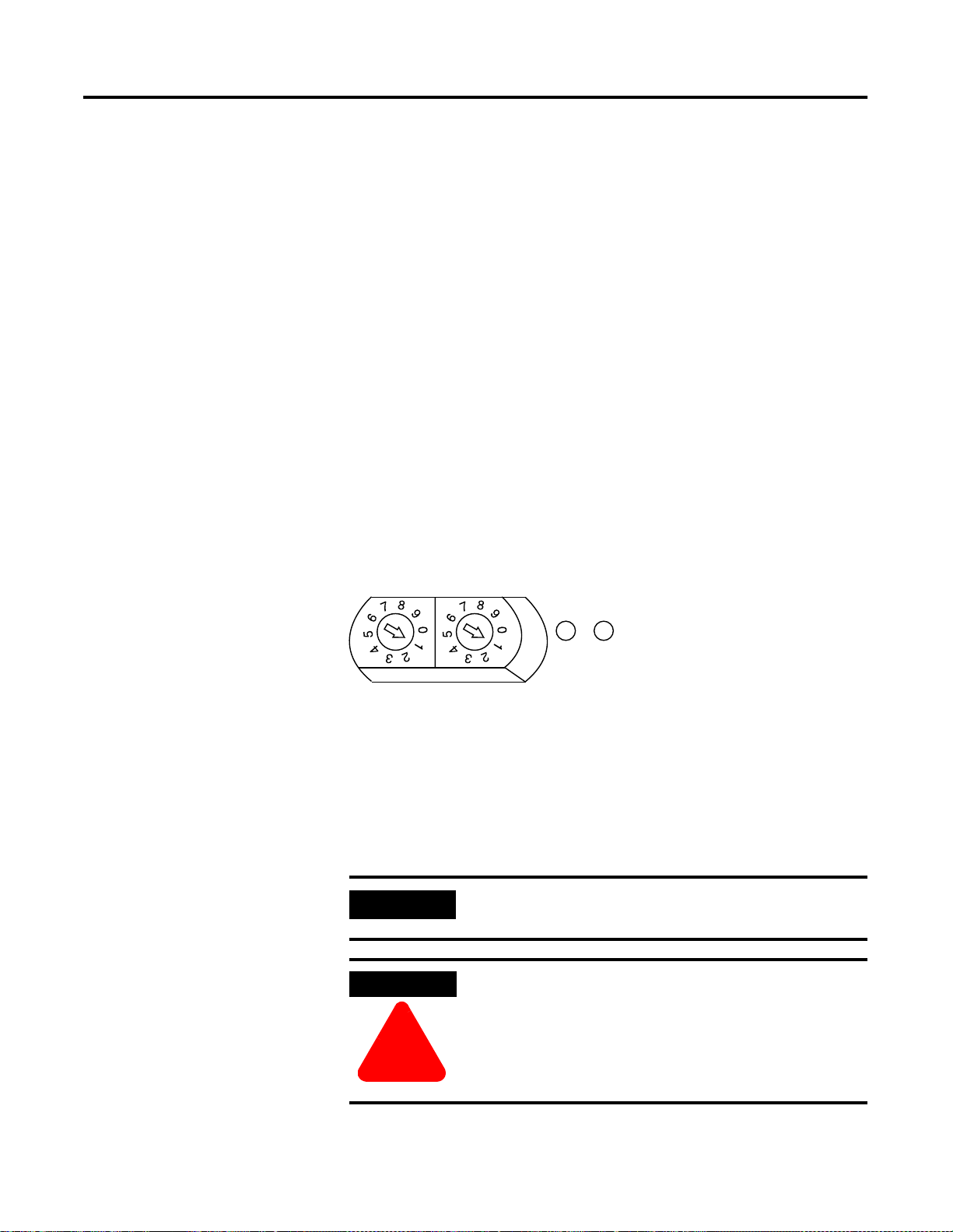
PROFIBUS Modules Installation, Wiring, Module Data, Status and Channel Configuration B-5
Installing CompactBlock LDX I/O
Follow these steps to install the block:
1. Set the Station Address on the Base Block
2. Mount the Base Block
3. Connect the PROFIBUS DP Terminal Connector
4. Connect Power to the Block
Set the Station Address on the Base Block
To set the station address, adjust the switches on the front of the base
block. The two siwtches are most significant digit (MSD) and least
significant digit (LSD). The switches can be set between 00 and 99 and
are read at base block power-up only. Figure B.1 shows an example
base block set for station address 11.
Figure B.1
NODE ADDRESS
MOD NET
STATUS
LSDMSD
43216
Mount the Base Block
You can mount the base block to a panel or DIN rail. We recommend
that you ground the panel or DIN rail before mounting the block.
IMPORTANT
WARNING
The analog base module can accommodate a
maximum of two discrete expansion modules.
When used in a Class I, Division 2, hazardous
location, this equipment must be mounted in a
suitable enclosure with proper wiring method that
complies with the governing electrical codes.
!
Publication 1790-UM001A-EN-P - March 2002
Page 74

B-6 PROFIBUS Modules Installation, Wiring, Module Data, Status and Channel Configuration
Panel Mounting
1. Place the block against the panel where you want to mount it.
2. Gently pull and position the expansion cover to the left.
3. Place a center punch, nail or similar device through the
mounting holes in the block and make two marks on the panel
(lower left and upper right corners of the module).
4. Remove the block and drill two holes in the panel to
accommodate each of the mounting screws.
Replace the block on the panel and place a screw through each of the
5.
two mounting holes. Tighten the screws until the block is firmly in
place.
95mm
3.74in
X
LD
ck
lo
CompactB
1790-16BVOX
41mm
1.6in
EXPANSION UNIT
0
0
7
16 INPUTS-DCPOWER
7
Expansion Cover
DIN Rail Mounting
1. Hook the top of slot of the block over the DIN Rail.
2.
Pull down on the locking lever while pressing the block against the
rail.
f
Locking Lever
3. Push up on the locking lever to secure the block to the rail
when block is flush against the rail.
Publication 1790-UM001A-EN-P - March 2002
Page 75

Horizontal mounting
PROFIBUS Modules Installation, Wiring, Module Data, Status and Channel Configuration B-7
Mount the Optional Expansion Blocks
Mount the expansion block by connecting it to a previously-installed
CompactBlock LDX I/O base or expansion block.
Beginning with the base block, you can mount your expansion blocks
either horizontally or vertically:
• horizontally (left to right) - add expansion blocks in a
end-to-end configuration
• vertically (up or down) - add expansion blocks either up or
down in a back-to-back configuration. In this configuration, you
must use the optional 15cm ribbon cable (1790-15CMCBL) and
alternately position the blocks in a right-side up, upside-down
fashion.
Vertical mounting
You can mount your blocks on a panel or DIN rail as described in the
previous section.
The longer expansion cable
(1790-15CMCBL) allows up to
7cm of space between blocks.
Publication 1790-UM001A-EN-P - March 2002
Page 76

B-8 PROFIBUS Modules Installation, Wiring, Module Data, Status and Channel Configuration
Connect the PROFIBUS DP Terminal Connector
Follow these procedures when connecting the PROFIBUS DP terminal
connector to the base block.
WARNING
!
The required PROFIBUS female 9-pin D-sub connector is not supplied
with the base block; you must purchase it separately. Before you
connect female 9-pin D-sub connector to the base block, make sure it
is wired correctly, as shown in Table B.2.
Table B . 2
Wiring Connections
Pin Number: Name: Description:
If you connect or disconnect the PROFIBUS cable
with power applied to this module or any device on
the network, an electrical arc can occur. This could
cause an explosion in hazardous location
installations. Be sure that power is removed or the
area is nonhazardous before proceeding.
1 Shield Shield, Protective Ground
2 M24V Minus 24V Output Voltage
3 RxD/TxD-P Receive/Transmit-Data-P
4 CNTR-P Control-p
5 DGND Data Ground
6 VP Voltage-Plus
7 P24V Plus 24V Output Voltage
8 RxD/TxD-N Receive/Transmit-Data-N
9 CNTR-N Control-N
Publication 1790-UM001A-EN-P - March 2002
Page 77

PROFIBUS Modules Installation, Wiring, Module Data, Status and Channel Configuration B-9
Once you have properly wired the connector, attach it to the base
block as shown in . Use the locking screws on the connector to fasten
it to the base block.
Figure B.2
PROFIBUS
Green - GND
Black - COM
Red - +24V dc
Connector
Connect Power to the Block
To apply power to the block, refer to Figure B.2.
Publication 1790-UM001A-EN-P - March 2002
Page 78

B-10 PROFIBUS Modules Installation, Wiring, Module Data, Status and Channel Configuration
Connecting I/O Wiring
Consider the following guidelines when wiring your system:
General Guidelines
• All module commons (ANLG COM) are connected in the analog
module. The analog common (ANLG COM) is not connected to
earth ground inside the module.
• Channels are not isolated from each other.
• Do not use the analog module’s NC terminals as connection
points.
• To ensure optimum accuracy, limit overall cable impedance by
keeping your cable as short as possible. Locate the I/O system
as close to your sensors or actuators as your application will
permit.
• Use Belden™ 8761, or equivalent, shielded wire.
• Keep shield connection to ground as short as possible.
• Under normal conditions, the drain wire and shield junction
must be connected to earth ground via a panel or DIN rail
mounting screw at the analog I/O module end.
Guidelines for Input Modules
• If multiple power supplies are used with analog inputs, the
power supply commons must be connected together.
• The module does not provide loop power for analog inputs. Use
a power supply that matches the input transmitter specifications.
Guidelines for Output Modules
• Current outputs (CH0 and CH1) of the 1790P-TNOC2 module
source current that returns to COM. Load resistance for a current
output channel must remain between 0 and 600
Ω .
Publication 1790-UM001A-EN-P - March 2002
Page 79

PROFIBUS Modules Installation, Wiring, Module Data, Status and Channel Configuration B-11
Wiring the Modules
ATTENTION
To prevent shock hazard, care should be taken when
wiring the module to analog signal sources. Before
wiring any analog module, disconnect power from
the system power supply and from any other source
to the analog module.
!
After the analog module is properly installed, follow the wiring
procedure below. To ensure proper operation and high immunity to
electrical noise, always use Belden™ 8761 (shielded, twisted-pair) or
equivalent wire.
ATTENTION
Never connect a voltage or current source to an
analog output channel.
!
signal wire
signal wire
cable
Cut foil shield
and drain wire
signal wire signal wiredrain wire foil shield
Publication 1790-UM001A-EN-P - March 2002
Page 80
B-12 PROFIBUS Modules Installation, Wiring, Module Data, Status and Channel Configuration
To wire your module follow these steps.
1. At each end of the cable, strip some casing to expose the
individual wires.
2. Trim the signal wires to 2-inch lengths. Strip about 3/16 inch (5
mm) of insulation away to expose the end of the wire.
ATTENTION
Be careful when stripping wires. Wire fragments that
fall into a module could cause damage at power up.
!
3. At one end of the cable, twist the drain wire and foil shield
together.
Under normal conditions, this drain wire and shield junction
must be connected to earth ground, via a panel or DIN rail
mounting screw at the analog I/O module end. Keep the length
of the drain wire as short as possible.
In environments where high frequency noise may be present, it
may be necessary to ground the cable shields to earth at the
module end via a 0.1µF capacitor at the sensor end for analog
inputs and at the load end for analog outputs.
4. At the other end of the cable, cut the drain wire and foil shield
back to the cable.
Publication 1790-UM001A-EN-P - March 2002
5. Connect the signal wires to the terminal block as shown in
Analog Input Wiring on page B-13 and Analog Output Wiring
on page B-14.
6. Connect the other end of the cable to the analog input or output
device.
7. Repeat steps 1 through 5 for each channel on the module.
Page 81

PROFIBUS Modules Installation, Wiring, Module Data, Status and Channel Configuration B-13
Analog Input Wiring
Use the information in Table B.3 and Figure B.3 to wire the
1790P-TN4C0 terminal block modules.
Table B. 3
1790P-TN4C0 Pin Descriptions
Pin Number: 135791113151719
Description:
Pin Number: 2468101214161820
Description:
(1)
+24V: Field Power (+) 24V dc
(2)
GND: Field Power (-) Ground
+24V
GND
(1)
CH0 CH1 CH2 CH3 NC NC NC NC NC
(2)
COM COM COM COM NC NC NC NC NC
Figure B.3
+24V
GND
+ –
24V dc
CH0
+
COM
–
mA
Publication 1790-UM001A-EN-P - March 2002
Page 82
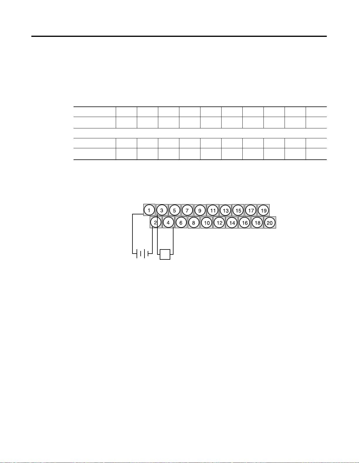
B-14 PROFIBUS Modules Installation, Wiring, Module Data, Status and Channel Configuration
Analog Output Wiring
Use the information in Table B.4 and Figure B.4 to wire the
1790P-TN0C2 terminal block modules.
Table B . 4
1790P-TN0C2 Pin Descriptions
Pin Number: 135791113151719
Description:
Pin Number: 2468101214161820
Description:
(1)
+24V: Field Power (+) 24V dc
(2)
GND: Field Power (-) Ground
+24V
GND
(1)
CH0 CH1 NC NC NC NC NC NC NC
(2)
COM COM NC NC NC NC NC NC NC
Figure B.4
+24V
GND
+ – +
24V dc
CH0
COM
–
L
43226
Publication 1790-UM001A-EN-P - March 2002
Page 83

PROFIBUS Modules Installation, Wiring, Module Data, Status and Channel Configuration B-15
1790P-TN4C0 Data Structure
Analog Input Image
The input image file represents data words and status bits. Input
words 0 through 3 hold the input data that represents the value of the
analog inputs for channels 0 through 3. These data words are valid
only when the channel is enabled and there are no errors. Input word
4 holds the status bits. Analog input data is presented as
raw/proportional.
Input words 5 and 6 contain input data for two optional discrete input
expansion modules.
1790P-N4C0/TN4C0 Configuration
Each analog current input may be configured for either the 4-20mA or
0-20mA range. This is most easily accomplished using the
programming software compatible with the controller or scanner. See
page B-16 for an example of configuration using the SST PROFIBUS
Configuration Tool.
Analog input data is presented as raw/proportional. The full 12-bit
resolution is used over the entire span of the input full scale range, as
shown in Table B.5.
Table B. 5
Input Full Scale
Range:
4-20mA 0000-0FFF 0-4095 3.90
0-20mA 0000-0FFF 0-4095 4.88
The input data files are the same as those shown for the
1790D-TN4CO. See page 3-2 for more information.
HEX Data Range: Decimal Data
Range:
Input Resolution:
µA
µA
Publication 1790-UM001A-EN-P - March 2002
Page 84

B-16 PROFIBUS Modules Installation, Wiring, Module Data, Status and Channel Configuration
1790P-TNOC2 Data Structure
Analog Output Image
The output image file represents data words. Output words 0 and 1
hold the output data that represents the value of the analog outputs
for channels 0 and 1. Analog output data is presented as
raw/proportional.
Output words 2 and 3 contain output data for two optional discrete
output expansion modules.
Analog output data is presented as raw/proportional. The full 12-bit
resolution is over the entire span of the output full scale range, as
shown in Table B.6.
Table B . 6
Output Full Scale
Range:
0-20mA 0000-0FFF 0-4095 4.88
The output data files are the same as those shown for the
1790D-TNOC2. See page 4-2 for more information.
HEX Data Range: Decimal Data
Range:
Input Resolution:
µA
Output Fault and Idle States
Configuring PROFIBUS Analog Modules
For PROFIBUS modules, analog outputs reset to zero (0) under fault
(communication failure) and idle (processor in program mode) states.
The values in the output data file are retained. Once a fault or idle
condition is cleared, the retained output values are sent to the analog
output channels.
You can use the PROFIBUS configuration software (with easy-to-use
GSD files) to configure the CompactBlock LDX analog modules
(1790P-TN4CO & 1790P-TNOC2).
To obtain GSD files, go to:
http://www.ab.com/networks/gsd
To read how to install the GSD file for your module, use the SST
PROFIBUS configuration tool documentation (e.g. online help). The
next section shows how to configure your analog module with the
SST PROFIBUS configuration tool.
Publication 1790-UM001A-EN-P - March 2002
Page 85
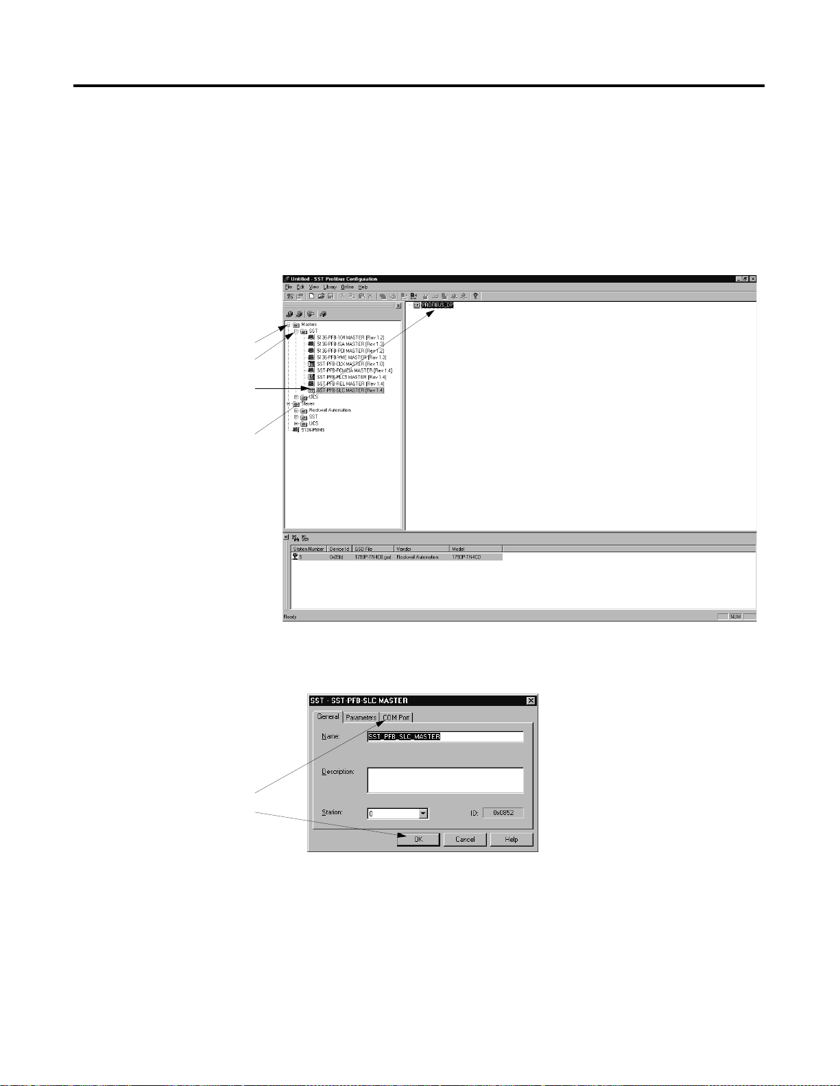
PROFIBUS Modules Installation, Wiring, Module Data, Status and Channel Configuration B-17
Configuring Analog Modules with the SST PROFIBUS Configuration Tool
A. Open the Masters
and the SST folders.
B. Choose your
PROFIBUS master.
C. Drag and drop the
master onto the
network.
The following configuration example shows how to configure your
analog modules with the SST PROFIBUS configuration tool. Follow
these steps:
1. Open your SST PROFIBUS configuration tool. If you are online,
make sure the processor is in Program mode.
2. Add the PROFIBUS master to your network.
Change any necessary
information and either:
• click to another tab
• click OK
3. Double-click on the master’s icon to see the device properties
pop-up screens. The first screen is the General properties.
Publication 1790-UM001A-EN-P - March 2002
Page 86
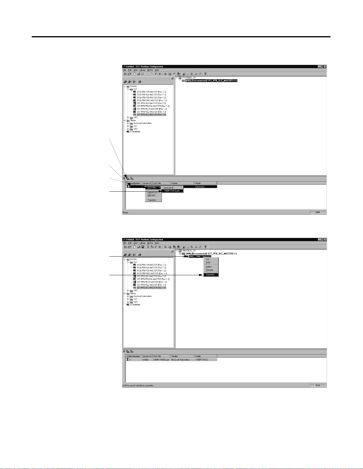
B-18 PROFIBUS Modules Installation, Wiring, Module Data, Status and Channel Configuration
4. Add slaves to the network.
A. If necessary, use the
search button to see
a list of stations on
the network.
B. Select the station.
C. Right-click to see
pop-up menu.
D. Choose the
appropriate GSD file
and the module
appears on the
network as shown.
A. Right-click on the
module to see the
pop-up menu.
B. Select Properties.
5. Access the module’s properties.
Publication 1790-UM001A-EN-P - March 2002
Page 87
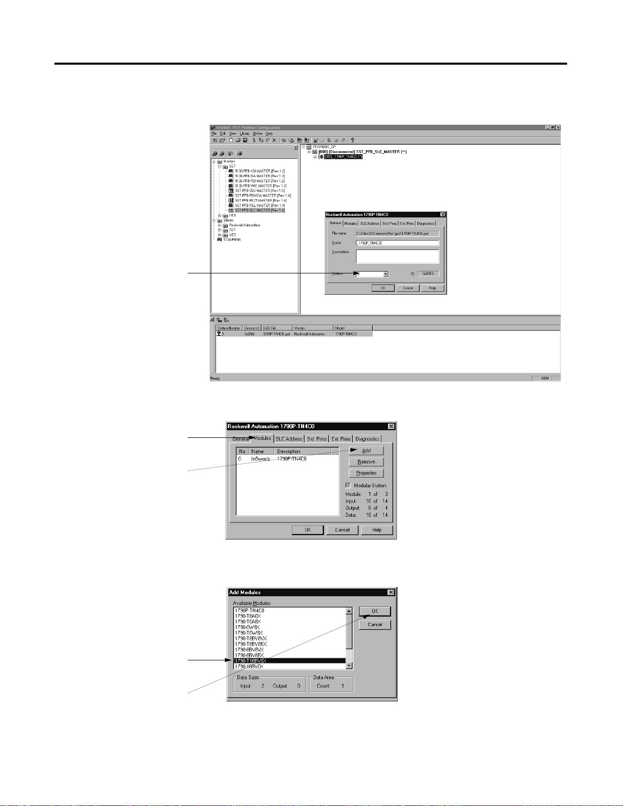
A. Make sure the
station number
is correct.
B. Click on other
tabs or OK
when finished
on this screen.
PROFIBUS Modules Installation, Wiring, Module Data, Status and Channel Configuration B-19
6. Use the pop-up screen shown below to change the module’s
properties.
A. Click on the
Modules tab.
B. Click on Add.
C. Choose the
module.
D. Click on OK.
7. If necessary, add additional modules as shown below.
The following screen appears to add modules.
Up to two expansion modules may be added to analog
base modules.
Publication 1790-UM001A-EN-P - March 2002
Page 88
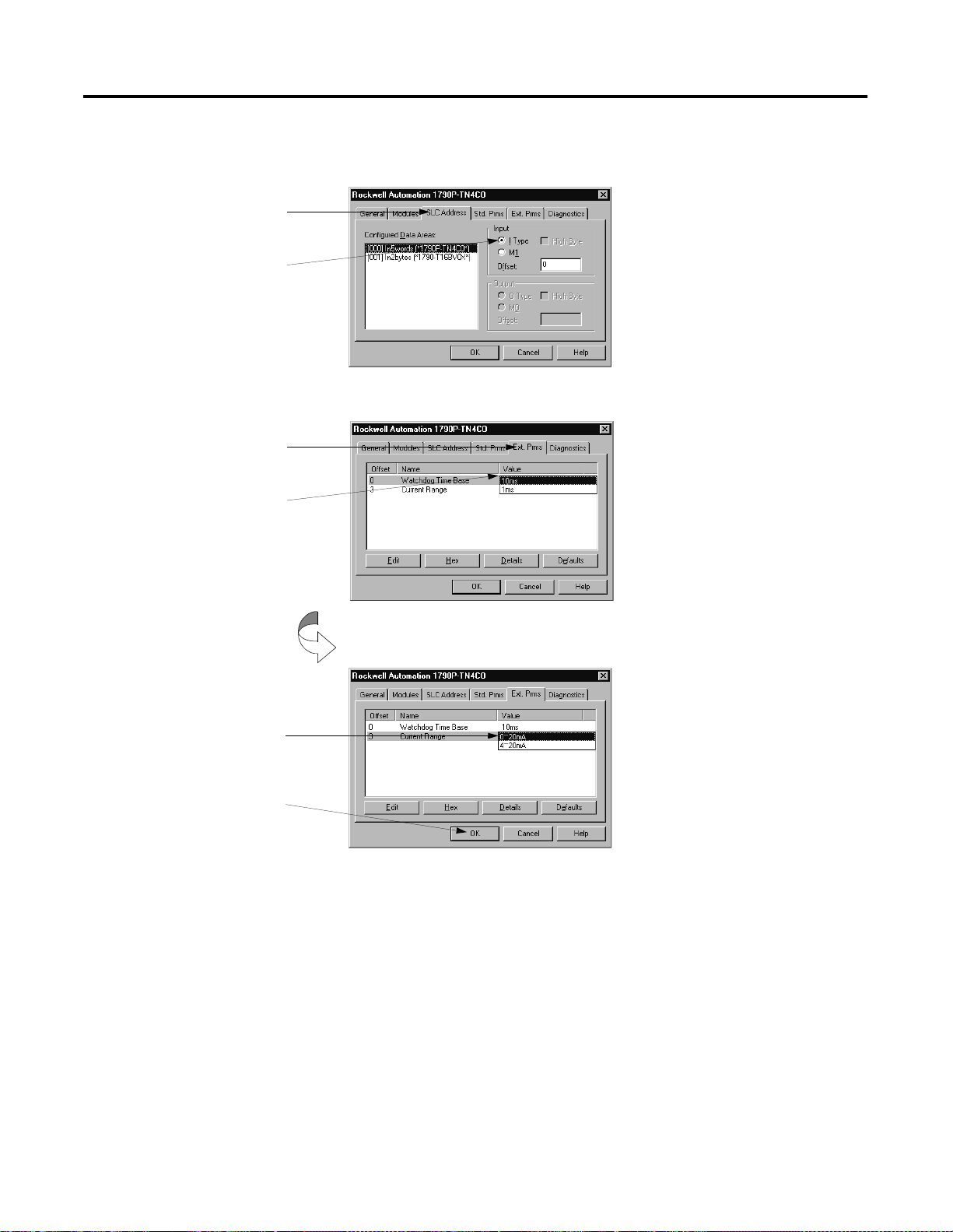
B-20 PROFIBUS Modules Installation, Wiring, Module Data, Status and Channel Configuration
8. Set the I/O type. This screen also shows the data size
information.
A. Click on the SLC
Addresses tab.
B. Choose the Input.
This example uses
the I Type input.
9. Set the Watchdog Time Base and Current Range.
A. Click on the Ext.
Prms tab.
B. Use the pull-down
menu to change
the Watchdog
Tim e Bas e.
C. Use the pull-down
menu to change
the Current Range.
D. Click OK when
finished.
Publication 1790-UM001A-EN-P - March 2002
10. Save the configuration file.
Page 89
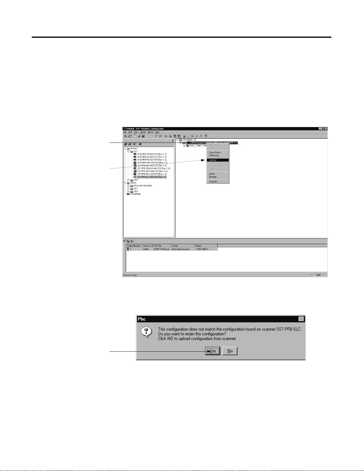
PROFIBUS Modules Installation, Wiring, Module Data, Status and Channel Configuration B-21
Downloading Configuration
A. Right-click on the
master to see the
pull-down menu.
B. Click on Connect.
To download configuration to the module, follow these steps:
1. Make sure the serial communication cable is connected between
the PC com port and the scanner serial port.
2. Verify that the processor is in Program mode.
3. Use the SST PROFIBUS configuration tool to connect to the
master.
Click on OK to retain
your configuration.
4. You may be notified about a configuration mismatch between
what is in the scanner and your current PROFIBUS project.
Choose YES to retain your configuration.
Publication 1790-UM001A-EN-P - March 2002
Page 90

B-22 PROFIBUS Modules Installation, Wiring, Module Data, Status and Channel Configuration
Any configuration mismatches are displayed in the software, as
shown in the screen below.
This example shows a
mismatch in the master
configuration.
A. Right-click on the
master to see the
pull-down menu.
B. Click on Load
Configuration.
5. Load configuration to the master.
Publication 1790-UM001A-EN-P - March 2002
6. If the scanner is online, the software prompts you and asks if
you want to load configuration. Choose YES.
Page 91

This master is in
Configured Program mode.
PROFIBUS Modules Installation, Wiring, Module Data, Status and Channel Configuration B-23
The master status changes to the Configured Program mode.
7. Change the processor to Run mode. In addition to solid green
indicator lights on the module, you should see the screen below.
Publication 1790-UM001A-EN-P - March 2002
Page 92

B-24 PROFIBUS Modules Installation, Wiring, Module Data, Status and Channel Configuration
PROFIBUS DP Specifications
Table B.7 lists the module specifications.
Table B . 7
PROFIBUS DP Specifications
Network Protocol PROFIBUS–DP (EN50170)
Redundancy Not supported
Repeater Control Signal RS-485 signal
Implementation Type DPC31
Freeze Mode Supported
Sync Mode Supported
Auto Baud Rate Supported
Fail Safe Mode Supported
Station Type Slave
FMS Support Not supported
Indicators 1 red/green - module status
1 red/green - network status
Number of Nodes 100 maximum - roatary switch type node address
setting (0-99)
Network Length/Communication Rate 9.6Kbps @ 1000m (3280ft)
19.2Kbps @ 1000m (3280ft)
45.45Kbps @ 1000m (3280ft)
93.75Kbps @ 1000m (3280ft)
187.5Kbps @ 1000m (3280ft)
500Kbps @ 400m (1312ft)
1.5mbps @ 200m (656ft)
3mbps @ 100m (328ft)
6mbps @ 100m (328ft)
12mbps @ 100m (328ft)
Publication 1790-UM001A-EN-P - March 2002
Isolation Type test 1250Vac rms for 60 seconds between
field power and PROFIBUS (I/O to logic)
PROFIBUS Power Supply voltage - 24V dc nominal
Voltage range - 19.2-28.8V dc
Power dissipation - 2W maximum @ 28.8V dc
Field Power Supply voltage - 24V dc nominal
Voltage range - 21.6-26.4V dc
Power dissipation - 1.5W maximum @ 26.4V dc
Page 93

PROFIBUS Modules Installation, Wiring, Module Data, Status and Channel Configuration B-25
Summary
This appendix describes PROFIBUS Modules Installation, Wiring,
Module Data, Status and Channel Configuration with the SST
PROFIBUS Configuration tool.
For more information, consult your PROFIBUS network, scanner and
network configuration tool documentation.
Publication 1790-UM001A-EN-P - March 2002
Page 94

B-26 PROFIBUS Modules Installation, Wiring, Module Data, Status and Channel Configuration
Notes:
Publication 1790-UM001A-EN-P - March 2002
Page 95

Glossary
The following terms and abbreviations are used throughout this
manual. For definitions of terms not listed here refer to Allen-Bradley’s
Industrial Automation Glossary, Publication AG-7.1.
A/D Converter– Refers to the analog to digital converter inherent to
the module. The converter produces a digital value whose magnitude
is proportional to the magnitude of an analog input signal.
analog input module – A module that contains circuits that convert
analog voltage or current input signals to digital values that can be
manipulated by the processor.
channel – Refers to analog input or output interfaces available on the
module’s terminal block. Each channel is configured for connection to
a variable voltage or current input or output device, and has its own
data and diagnostic status words.
channel update time – The time required for the module to sample
and convert the input signals of one enabled input channel and
update the channel data word.
configuration word – Contains the channel configuration
information needed by the module to configure and operate each
channel.
D/A Converter – Refers to the digital to analog converter inherent to
the output module. The converter produces an analog dc voltage or
current signal whose instantaneous magnitude is proportional to the
magnitude of a digital value.
data word – A 16-bit integer that represents the value of the analog
input or output channel. The channel data word is valid only when
the channel is enabled and there are no channel errors. When the
channel is disabled the channel data word is cleared (0).
full scale – The magnitude of voltage or current over which normal
operation is permitted.
full scale error – (gain error) The difference in slope between the
actual and ideal analog transfer functions.
full scale range – (FSR) The difference between the maximum and
minimum specified analog input values.
1 Publication 1790-UM001A-EN-P - March 2002
Page 96

Glossary 2
input image – The input from the module to the controller. The input
image contains the module data words and status bits.
LSB – (Least Significant Bit) The bit that represents the smallest value
within a string of bits.
For analog modules, the LSB is defined as the rightmost bit, bit 0, of
the 16-bit field.
linearity error – An analog input or output is composed of a series
of voltage or current values corresponding to digital codes. For an
ideal analog input or output, the values lie in a straight line spaced by
a voltage or current corresponding to 1 LSB. Any deviation of the
converted input or actual output from this line is the linearity error of
the input or output. The linearity is expressed in percent of full scale
input or output. See the variation from the straight line due to linearity
error (exaggerated) in the example below.
Actual Transfer
Function
Ideal Transfer
number of significant bits – The power of two that represents the
total number of completely different digital codes an analog signal can
be converted into or generated from.
module scan time – same as module update time
module update time – For input modules, the time required for the
module to sample and convert the input signals of all enabled input
channels and make the resulting data values available to the
processor. For output modules, the time required for the module to
receive the digital code from the processor, convert it to the analog
output signal, and send it to the output channel.
multiplexer – An switching system that allows several signals to
share a common A/D or D/A converter.
normal operating range – Input or output signals are within the
configured range. See for a list of input and output types/ranges.
Publication 1790-UM001A-EN-P - March 2002
Page 97

Glossary 3
overall accuracy – The worst-case deviation of the output voltage or
current from the ideal over the full output range is the overall
accuracy. For inputs, the worst-case deviation of the digital
representation of the input signal from the ideal over the full input
range is the overall accuracy. this is expressed in percent of full scale.
Gain error, offset error, and linearity error all contribute to input and
output channel accuracy.
output accuracy – The difference between the actual analog output
value and what is expected, when a given digital code is applied to
the d/a converter. Expressed as a ± percent of full scale. The error will
include gain, offset and drift elements, and is defined at 25°C, and also
over the full operating temperature range (0 to 60°C).
output image – The output from the controller to the output module.
The output image contains the analog output data.
analog output module – An I/O module that contains circuits that
output an analog dc voltage or current signal proportional to a digital
value transferred to the module from the processor.
repeatability – The closeness of agreement among repeated
measurements of the same variable under the same conditions.
resolution – The smallest detectable change in a measurement,
typically expressed in engineering units (e.g. 1 mV) or as a number of
bits. For example a 12-bit system has 4095 possible output states. It
can therefore measure 1 part in 4095.
status word – Contains status information about the channel’s current
configuration and operational state. You can use this information in
your ladder program to determine whether the channel data word is
valid.
step response time – For inputs, this is the time required for the
channel data word signal to reach a specified percentage of its
expected final value, given a large step change in the input signal.
update time – see “module update time”
Publication 1790-UM001A-EN-P - March 2002
Page 98

Glossary 4
Notes:
Publication 1790-UM001A-EN-P - March 2002
Page 99

Index
A
A/D
definition
abbreviations Glossary-1
analog input module
definition
overview 1-1
Glossary-1
Glossary-1
C
channel
definition
channel diagnostics 5-4
channel status LED 1-4
channel update time
definition
configuration word
definition
contacting Rockwell Automation 5-7
current draw
1769-IF4
1769-OF2 2-1
Glossary-1
Glossary-1
Glossary-1
2-1
D
D/A converter
definition
data word
definition
definition of terms Glossary-1
Glossary-1
Glossary-1
E
electrical noise 2-3
F
fault condition
at power-up
FSR. See full scale range.
full scale
definition
full scale error
definition
full scale range
definition
1-4
Glossary-1
Glossary-1
Glossary-1
G
gain error. See full scale error.
H
heat considerations 2-3
I
input image
definition
installation 2-1–??
heat and noise considerations 2-3
Glossary-2
L
least significant bit. See LSB.
5-1
LED
linearity error
definition
LSB
definition
Glossary-2
Glossary-2
M
module scan time
definition
module update time
definition
multiplexer
definition
Glossary-2
Glossary-2
Glossary-2
N
number of significant bits
definition
Glossary-2
O
open-circuit detection 5-4
operation
1-4
system
out-of-range detection 5-4
output image
definition
overall accuracy
definition
Glossary-3
Glossary-3
P
power-up diagnostics 5-3
power-up sequence 1-4
program alteration 5-2
Publication 1790-UM001A-EN-P - March 2002
Page 100

2 Index
R
resolution
definition
Glossary-3
S
safety circuits 5-2
scan time Glossary-2
specifications A-1
status word
definition
step response time
definition
system operation 1-4
Glossary-3
Glossary-3
T
troubleshooting
safety considerations
U
update time. See channel update time.
update time. See module update time.
W
wiring 2-1
input module 2-15–??
input terminal layout 2-15, 2-16, 2-17,
2-18
modules 2-13
output module 2-16, 2-18
routing considerations 2-3
5-1
Publication 1790-UM001A-EN-P - March 2002
 Loading...