

Page 1

User Manual
SoftLogix 5800 System
Catalog Numbers 1789-L10, 1789-L30, 1789-L60
Page 2
Important User Information
IMPORTANT
Solid-state equipment has operational characteristics differing from those of electromechanical equipment. Safety
Guidelines for the Application, Installation and Maintenance of Solid State Controls (publication SGI-1.1
your local Rockwell Automation sales office or online at http://www.rockwellautomation.com/literature/
important differences between solid-state equipment and hard-wired electromechanical devices. Because of this difference,
and also because of the wide variety of uses for solid-state equipment, all persons responsible for applying this equipment
must satisfy themselves that each intended application of this equipment is acceptable.
In no event will Rockwell Automation, Inc. be responsible or liable for indirect or consequential damages resulting from the
use or application of this equipment.
The examples and diagrams in this manual are included solely for illustrative purposes. Because of the many variables and
requirements associated with any particular installation, Rockwell Automation, Inc. cannot assume responsibility or
liability for actual use based on the examples and diagrams.
No patent liability is assumed by Rockwell Automation, Inc. with respect to use of information, circuits, equipment, or
software described in this manual.
Reproduction of the contents of this manual, in whole or in part, without written permission of Rockwell Automation,
Inc., is prohibited.
Throughout this manual, when necessary, we use notes to make you aware of safety considerations.
available from
) describes some
WARNING: Identifies information about practices or circumstances that can cause an explosion in a hazardous environment,
which may lead to personal injury or death, property damage, or economic loss.
ATTENTION: Identifies information about practices or circumstances that can lead to personal injury or death, property
damage, or economic loss. Attentions help you identify a hazard, avoid a hazard, and recognize the consequence.
SHOCK HAZARD: Labels may be on or inside the equipment, for example, a drive or motor, to alert people that dangerous
voltage may be present.
BURN HAZARD: Labels may be on or inside the equipment, for example, a drive or motor, to alert people that surfaces may
reach dangerous temperatures.
Identifies information that is critical for successful application and understanding of the product.
Allen-Bradley, Rockwell Software, RSLog ix, FactoryTalk, SoftLogix, R SLinx, ControlLogix, Studio 5000, Rockwell Automation, SLC, PLC-5, Logix5000, PhaseManager, ControlLogix, RSNetWorx, FlexLogix, PLC-2,
PLC-3, DH+, Integrated Architecture, Kinetix, Flex, PanelView, and TechConnect are trademarks of Rockwell Automation, Inc.
Trademarks not belonging to Rockwell Automation are property of their respective companies.
Page 3

Summary of Changes
Introduction
Updated Information
The release of this document contains new and updated information. To find
new and updated information, look for change bars, as shown next to this
paragraph.
The document contains these changes. This table represents major topics. Make
sure to look for the change bars throughout this document.
Top ic Pa ge
Troubleshoot FactoryTalk Activations Link 17
Logix Designer software has now replaced RSLogix™ 5000 software Throughout
Studio 5000™ Logix Designer application is the rebranding of RSLogix 5000 software 11
DeviceNet is supported in SoftLogix software, Version 20 or earlier 159
ControlNet is supported in SoftLogix software, Version 20 or earlier 193
Rockwell Automation Publication 1789-UM002J-EN-P - December 2012 3
Page 4

Summary of Changes
Notes:
4 Rockwell Automation Publication 1789-UM002J-EN-P - December 2012
Page 5

Table of Contents
Preface
What is the SoftLogix System?
Studio 5000 Environment . . . . . . . . . . . . . . . . . . . . . . . . . . . . . . . . . . . . . . . . 11
Additional Resources . . . . . . . . . . . . . . . . . . . . . . . . . . . . . . . . . . . . . . . . . . . . . 12
Chapter 1
About the SoftLogix 5800 Controller. . . . . . . . . . . . . . . . . . . . . . . . . . . . . . 13
Before You Begin . . . . . . . . . . . . . . . . . . . . . . . . . . . . . . . . . . . . . . . . . . . . . . . . 14
Install the SoftLogix 5800 Controller . . . . . . . . . . . . . . . . . . . . . . . . . . . . . . 15
FactoryTalk Activation Manager . . . . . . . . . . . . . . . . . . . . . . . . . . . . . . . . . . 15
Node-locked Activation. . . . . . . . . . . . . . . . . . . . . . . . . . . . . . . . . . . . . . . 15
Concurrent Activation. . . . . . . . . . . . . . . . . . . . . . . . . . . . . . . . . . . . . . . . 15
Run the FactoryTalk Activation Manager . . . . . . . . . . . . . . . . . . . . . . 16
Activation Tools and Rehosting . . . . . . . . . . . . . . . . . . . . . . . . . . . . . . . 17
Troubleshoot FactoryTalk Activations . . . . . . . . . . . . . . . . . . . . . . . . . 17
Configure the RSLinx Virtual-backplane Driver . . . . . . . . . . . . . . . . . . . . 18
Troubleshoot the SoftLogix 5800 Controller . . . . . . . . . . . . . . . . . . . 19
Chapter 2
SoftLogix System Components. . . . . . . . . . . . . . . . . . . . . . . . . . . . . . . . . . . . 22
SoftLogix System Description . . . . . . . . . . . . . . . . . . . . . . . . . . . . . . . . . 23
Set Up the Chassis Monitor. . . . . . . . . . . . . . . . . . . . . . . . . . . . . . . . . . . . . . . 24
Determine a Memory Size. . . . . . . . . . . . . . . . . . . . . . . . . . . . . . . . . . . . . 25
Specify a Periodic Save Interval . . . . . . . . . . . . . . . . . . . . . . . . . . . . . . . . 26
Configure the SoftLogix Controller . . . . . . . . . . . . . . . . . . . . . . . . . . . . . . . 27
Step 1: Create and Configure the Controller
in the SoftLogix Chassis Monitor . . . . . . . . . . . . . . . . . . . . . . . . . . 27
Change the RSLinx Software Slot. . . . . . . . . . . . . . . . . . . . . . . . . . . . . . 29
Step 2: Create the New Controller Project in
RSLogix 5000 Software . . . . . . . . . . . . . . . . . . . . . . . . . . . . . . . . . . . 31
Step 3: Configure the Controller in the RSLogix 5000 Project . . . 32
Developing Programs. . . . . . . . . . . . . . . . . . . . . . . . . . . . . . . . . . . . . . . . . . . . . 34
Configuring Tasks. . . . . . . . . . . . . . . . . . . . . . . . . . . . . . . . . . . . . . . . . . . . 34
Determining Programs. . . . . . . . . . . . . . . . . . . . . . . . . . . . . . . . . . . . . . . . 36
Supporting Routines. . . . . . . . . . . . . . . . . . . . . . . . . . . . . . . . . . . . . . . . . . 37
Instruction Execution. . . . . . . . . . . . . . . . . . . . . . . . . . . . . . . . . . . . . . . . . 37
How the SoftLogix System Uses Connections . . . . . . . . . . . . . . . . . . . . . . 38
Connections for Produced and Consumed Tags . . . . . . . . . . . . . . . . . . . . 38
Connections for Messages . . . . . . . . . . . . . . . . . . . . . . . . . . . . . . . . . . . . . . . . 38
Connections for I/O Modules . . . . . . . . . . . . . . . . . . . . . . . . . . . . . . . . . . . . 40
Total Connection Requirements . . . . . . . . . . . . . . . . . . . . . . . . . . . . . . . . . . 40
Restart the Controller . . . . . . . . . . . . . . . . . . . . . . . . . . . . . . . . . . . . . . . . . . . . 41
Online with the Controller. . . . . . . . . . . . . . . . . . . . . . . . . . . . . . . . . . . . 41
Upload to the Controller . . . . . . . . . . . . . . . . . . . . . . . . . . . . . . . . . . . . . 41
Select a System Overhead Percentage . . . . . . . . . . . . . . . . . . . . . . . . . . . . . . 42
Rockwell Automation Publication 1789-UM002J-EN-P - December 2012 5
Page 6

Table of Contents
Chapter 3
Communicate with Devices on an
Ethernet Network
Configure Your System for an Ethernet Network . . . . . . . . . . . . . . . . . . . 43
Step 1: Disable UDP Messages in RSLinx Classic Software . . . . . . . 44
Disabling the UDP option. . . . . . . . . . . . . . . . . . . . . . . . . . . . . . . . . . . . . 45
Enabling the UDP option . . . . . . . . . . . . . . . . . . . . . . . . . . . . . . . . . . . . . 46
Step 2: Create the Communication Card in
the SoftLogix Chassis Monitor . . . . . . . . . . . . . . . . . . . . . . . . . . . . . 48
Step 3: Configure the Communication Card as Part of the Project 50
Step 4: Configure the SoftLogix EtherNet/IP Module to
Communicate on an Ethernet Network. . . . . . . . . . . . . . . . . . . . . 53
Multiple EtherNet/IP Modules. . . . . . . . . . . . . . . . . . . . . . . . . . . . . . . . . . . . 54
Ethernet Communication . . . . . . . . . . . . . . . . . . . . . . . . . . . . . . . . . . . . . 54
Domain Interactions. . . . . . . . . . . . . . . . . . . . . . . . . . . . . . . . . . . . . . . . . . 54
Controller Connections over the EtherNet/IP Network. . . . . . . . . . . . . 55
Supported Functionality of the SoftLogix 5800
EtherNet/IP Module . . . . . . . . . . . . . . . . . . . . . . . . . . . . . . . . . . . . . . 56
Distributed Ethernet I/O . . . . . . . . . . . . . . . . . . . . . . . . . . . . . . . . . . . . . . . . . 56
I/O Configuration Order in the Project . . . . . . . . . . . . . . . . . . . . . . . . 56
Ethernet I/O Data. . . . . . . . . . . . . . . . . . . . . . . . . . . . . . . . . . . . . . . . . . . . 58
Add a Remote Controller . . . . . . . . . . . . . . . . . . . . . . . . . . . . . . . . . . . . . . . . . 60
Add a Consumed Tag . . . . . . . . . . . . . . . . . . . . . . . . . . . . . . . . . . . . . . . . . 61
Check EtherNet/IP Statistics. . . . . . . . . . . . . . . . . . . . . . . . . . . . . . . . . . . . . . 63
Example 1: Workstation Remotely Connected
to a SoftLogix Controller . . . . . . . . . . . . . . . . . . . . . . . . . . . . . . . . . . . . . . 65
Example 2: Send Messages over the EtherNet/IP Network. . . . . . . . . . . 68
Configure a MSG Instruction. . . . . . . . . . . . . . . . . . . . . . . . . . . . . . . . . . 69
Example 3: Send Messages over the EtherNet/IP Network
to a PLC-5 Processor . . . . . . . . . . . . . . . . . . . . . . . . . . . . . . . . . . . . . . . . . . 71
Configure a MSG Instruction. . . . . . . . . . . . . . . . . . . . . . . . . . . . . . . . . . 71
Example 4: Control Distributed I/O . . . . . . . . . . . . . . . . . . . . . . . . . . . . . . . 73
Chapter 4
Communicate with Serial Devices
6 Rockwell Automation Publication 1789-UM002J-EN-P - December 2012
Configure Your System for a Serial Device. . . . . . . . . . . . . . . . . . . . . . . . . . 75
Step 1: Configure the Serial Port . . . . . . . . . . . . . . . . . . . . . . . . . . . . . . . 76
Change the COM Port Setting . . . . . . . . . . . . . . . . . . . . . . . . . . . . . . . . 78
Step 2: Configure the Serial Port of the Controller in the Project . 81
Controller Status Indicators. . . . . . . . . . . . . . . . . . . . . . . . . . . . . . . . . . . . . . . 85
Example 1: Workstation Directly Connected
to a SoftLogix Controller . . . . . . . . . . . . . . . . . . . . . . . . . . . . . . . . . . . . . . 85
DF1 Point-to-Point Configuration. . . . . . . . . . . . . . . . . . . . . . . . . . . . . 86
Example 2: Workstation Remotely Connected
to a SoftLogix Controller . . . . . . . . . . . . . . . . . . . . . . . . . . . . . . . . . . . . . . 86
Master and Slave Communication Methods . . . . . . . . . . . . . . . . . . . . 87
DF1 Slave Configuration. . . . . . . . . . . . . . . . . . . . . . . . . . . . . . . . . . . . . . 88
DF1 Master Configuration . . . . . . . . . . . . . . . . . . . . . . . . . . . . . . . . . . . . 88
Example 3: SoftLogix Controller to a Bar Code Reader . . . . . . . . . . . . . . 90
Page 7

Configure and Use Simulated I/O
Table of Contents
Connect the ASCII Device to the Controller . . . . . . . . . . . . . . . . . . . 90
User Mode Configuration. . . . . . . . . . . . . . . . . . . . . . . . . . . . . . . . . . . . . 91
ASCII Instructions . . . . . . . . . . . . . . . . . . . . . . . . . . . . . . . . . . . . . . . . . . . 92
Chapter 5
Configure Your System for a 1789-SIM Module . . . . . . . . . . . . . . . . . . . . 93
Step 1: Create the 1789-SIM Module in the SoftLogix Chassis
Monitor . . . . . . . . . . . . . . . . . . . . . . . . . . . . . . . . . . . . . . . . . . . . . . . . . 94
Step 2: Configure the 1789-SIM module as Part of the Project . . . 97
Map I/O Data to the 1789-SIM Module . . . . . . . . . . . . . . . . . . . . . . . . . . 100
Toggle Inputs and Monitor Outputs. . . . . . . . . . . . . . . . . . . . . . . . . . . . . . 101
Turn On or Force a Bit . . . . . . . . . . . . . . . . . . . . . . . . . . . . . . . . . . . . . . 102
Example: Move Application Data into the 1789-SIM Tags . . . . . . . . . 103
Chapter 6
Execute External Routines
Develop External Routines
Configure Your System to Execute an External Routine . . . . . . . . . . . . 105
Add an External Routine to the Controller Organizer. . . . . . . . . . . . . . 106
How the Project Stores and Downloads an External Routine. . . . 111
Call an External Routine. . . . . . . . . . . . . . . . . . . . . . . . . . . . . . . . . . . . . . . . . 112
Jump to External Routine (JXR). . . . . . . . . . . . . . . . . . . . . . . . . . . . . . 112
Operands . . . . . . . . . . . . . . . . . . . . . . . . . . . . . . . . . . . . . . . . . . . . . . . . . . . 112
Description . . . . . . . . . . . . . . . . . . . . . . . . . . . . . . . . . . . . . . . . . . . . . . . . . 113
Arithmetic Status Flags . . . . . . . . . . . . . . . . . . . . . . . . . . . . . . . . . . . . . . 113
Fault Conditions . . . . . . . . . . . . . . . . . . . . . . . . . . . . . . . . . . . . . . . . . . . . 114
Execution. . . . . . . . . . . . . . . . . . . . . . . . . . . . . . . . . . . . . . . . . . . . . . . . . . . 114
Type Checking . . . . . . . . . . . . . . . . . . . . . . . . . . . . . . . . . . . . . . . . . . . . . . . . . 114
Chapter 7
Considerations For External Routines . . . . . . . . . . . . . . . . . . . . . . . . . . . . 115
How the SoftLogix Controller Executes External Routines . . . . . . . . . 116
How the Project Stores and Downloads an External Routine. . . . 117
Create Synchronous, Single-threaded External Routines. . . . . . . . . . . . 117
Create a Visual Studio Project . . . . . . . . . . . . . . . . . . . . . . . . . . . . . . . . 117
Project Files . . . . . . . . . . . . . . . . . . . . . . . . . . . . . . . . . . . . . . . . . . . . . . . . . . . . 118
RA_ExternalRoutines.h. . . . . . . . . . . . . . . . . . . . . . . . . . . . . . . . . . . . . . 119
InlineExample.cpp. . . . . . . . . . . . . . . . . . . . . . . . . . . . . . . . . . . . . . . . . . . 121
InlineExample.h. . . . . . . . . . . . . . . . . . . . . . . . . . . . . . . . . . . . . . . . . . . . . 122
Create an HTML Resource . . . . . . . . . . . . . . . . . . . . . . . . . . . . . . . . . . . . . . 123
Add Version Information to an External Routine DLL. . . . . . . . . . . . . 128
Build and Download External Routines . . . . . . . . . . . . . . . . . . . . . . . . . . . 130
Update an Existing External Routine . . . . . . . . . . . . . . . . . . . . . . . . . . . . . 130
Create Multi-threaded External Routines . . . . . . . . . . . . . . . . . . . . . . . . . 130
Sounds.cpp . . . . . . . . . . . . . . . . . . . . . . . . . . . . . . . . . . . . . . . . . . . . . . . . . 131
Thread Priorities in a Multithreaded External Routine DLL . . . . 135
Debug External Routines . . . . . . . . . . . . . . . . . . . . . . . . . . . . . . . . . . . . . . . . 136
Set Up the Debug Session . . . . . . . . . . . . . . . . . . . . . . . . . . . . . . . . . . . . 136
Rockwell Automation Publication 1789-UM002J-EN-P - December 2012 7
Page 8

Table of Contents
Start a Debug Session . . . . . . . . . . . . . . . . . . . . . . . . . . . . . . . . . . . . . . . . 137
Set Breakpoints in External Routine Code . . . . . . . . . . . . . . . . . . . . . 138
Data Type Support . . . . . . . . . . . . . . . . . . . . . . . . . . . . . . . . . . . . . . . . . . . . . . 138
ARRAY Example . . . . . . . . . . . . . . . . . . . . . . . . . . . . . . . . . . . . . . . . . . . . 139
INTEGER Example . . . . . . . . . . . . . . . . . . . . . . . . . . . . . . . . . . . . . . . . . 140
STRUCTURE Example . . . . . . . . . . . . . . . . . . . . . . . . . . . . . . . . . . . . . 141
STRING Example . . . . . . . . . . . . . . . . . . . . . . . . . . . . . . . . . . . . . . . . . . . 142
Packing in Structures. . . . . . . . . . . . . . . . . . . . . . . . . . . . . . . . . . . . . . . . . 143
Parameter Type Checking . . . . . . . . . . . . . . . . . . . . . . . . . . . . . . . . . . . . 144
Return Parameter. . . . . . . . . . . . . . . . . . . . . . . . . . . . . . . . . . . . . . . . . . . . 144
Export Functions by Using C++ Export Style . . . . . . . . . . . . . . . . . . . . . 144
InlineExample.h . . . . . . . . . . . . . . . . . . . . . . . . . . . . . . . . . . . . . . . . . . . . . 145
InlineExample.cpp . . . . . . . . . . . . . . . . . . . . . . . . . . . . . . . . . . . . . . . . . . . 145
Run dumpbin.exe. . . . . . . . . . . . . . . . . . . . . . . . . . . . . . . . . . . . . . . . . . . . 145
Edit XML Resource. . . . . . . . . . . . . . . . . . . . . . . . . . . . . . . . . . . . . . . . . . 146
Other Considerations . . . . . . . . . . . . . . . . . . . . . . . . . . . . . . . . . . . . . . . . . . . 146
Pass Tags by Reference . . . . . . . . . . . . . . . . . . . . . . . . . . . . . . . . . . . . . . . 146
External Routine DLL that Uses Other DLLs. . . . . . . . . . . . . . . . . . 146
Program Windows Events to Monitor
and Change Controller Execution
Communicate with Devices on a
DeviceNet Network
Chapter 8
Use Outbound Events . . . . . . . . . . . . . . . . . . . . . . . . . . . . . . . . . . . . . . . . . . . 147
Programming Example: Outbound Events . . . . . . . . . . . . . . . . . . . . . 148
Configure Windows Events to Launch Tasks within the SoftLogix
Controller. . . . . . . . . . . . . . . . . . . . . . . . . . . . . . . . . . . . . . . . . . . . . . . . . . . 151
Configure a Windows-event Task in the Controller . . . . . . . . . . . . 151
Trigger a Controller Task from a Windows Application . . . . . . . . 154
Programming Example: Windows Event. . . . . . . . . . . . . . . . . . . . . . . 154
Programmatically Saving the Controller . . . . . . . . . . . . . . . . . . . . . . . . . . . 156
Programming Example: Programmatic Save of Controller. . . . . . . 156
Appendix A
Configure Your System for a DeviceNet Network. . . . . . . . . . . . . . . . . . 160
Step 1: Install the Hardware . . . . . . . . . . . . . . . . . . . . . . . . . . . . . . . . . . 160
Step 2: Create the Communication Card in the SoftLogix Chassis
Monitor. . . . . . . . . . . . . . . . . . . . . . . . . . . . . . . . . . . . . . . . . . . . . . . . . 161
Step 3: Install the Communication Driver . . . . . . . . . . . . . . . . . . . . . 164
Step 4: Configure the Communication Card as Part of the Project . . .
167
Step 5: Download the Project to the Controller . . . . . . . . . . . . . . . . 169
Step 6: Define the Scanlist. . . . . . . . . . . . . . . . . . . . . . . . . . . . . . . . . . . . 170
Perform DeviceNet Test . . . . . . . . . . . . . . . . . . . . . . . . . . . . . . . . . . . . . . . . . 179
Step 1: Start the Test Application . . . . . . . . . . . . . . . . . . . . . . . . . . . . . 179
Step 2: Configure the Port. . . . . . . . . . . . . . . . . . . . . . . . . . . . . . . . . . . . 180
Step 3: Create a View . . . . . . . . . . . . . . . . . . . . . . . . . . . . . . . . . . . . . . . . 182
Step 4: Read Inputs and Write Outputs . . . . . . . . . . . . . . . . . . . . . . . 184
Step 5: Change the Scanner Mode. . . . . . . . . . . . . . . . . . . . . . . . . . . . . 185
8 Rockwell Automation Publication 1789-UM002J-EN-P - December 2012
Page 9

Table of Contents
DeviceNet I/O Data . . . . . . . . . . . . . . . . . . . . . . . . . . . . . . . . . . . . . . . . . . . . 186
Determine How Often to Update Data . . . . . . . . . . . . . . . . . . . . . . . 187
Place the Communication Card in Run Mode . . . . . . . . . . . . . . . . . . . . . 188
CommandRegister Bits . . . . . . . . . . . . . . . . . . . . . . . . . . . . . . . . . . . . . . 188
StatusRegister. . . . . . . . . . . . . . . . . . . . . . . . . . . . . . . . . . . . . . . . . . . . . . . . . . . 189
Status Data Elements . . . . . . . . . . . . . . . . . . . . . . . . . . . . . . . . . . . . . . . . 190
Example: SoftLogix Controller and DeviceNet I/O . . . . . . . . . . . . . . . . 191
Create Alias Tags. . . . . . . . . . . . . . . . . . . . . . . . . . . . . . . . . . . . . . . . . . . . 192
Appendix B
Communicate with Devices on a
ControlNet Network
Configure Your System for a ControlNet Network . . . . . . . . . . . . . . . . 193
Step 1: Install the Hardware. . . . . . . . . . . . . . . . . . . . . . . . . . . . . . . . . . 194
Step 2: Create the Communication Card in the SoftLogix Chassis
Monitor . . . . . . . . . . . . . . . . . . . . . . . . . . . . . . . . . . . . . . . . . . . . . . . . 195
Step 3: Configure the Communication Card as Part of the Project. . .
198
Step 4: Add Remote Communication Devices for the Communication
Card. . . . . . . . . . . . . . . . . . . . . . . . . . . . . . . . . . . . . . . . . . . . . . . . . . . . 201
Step 5: Download the Project to the Controller . . . . . . . . . . . . . . . . 207
Step 6: Schedule the Network . . . . . . . . . . . . . . . . . . . . . . . . . . . . . . . . 209
ControlNet I/O Data . . . . . . . . . . . . . . . . . . . . . . . . . . . . . . . . . . . . . . . . . . . 215
Rack-optimized Connections. . . . . . . . . . . . . . . . . . . . . . . . . . . . . . . . . 216
Direct Connections . . . . . . . . . . . . . . . . . . . . . . . . . . . . . . . . . . . . . . . . . 217
Example 1: SoftLogix Controller and ControlNet I/O . . . . . . . . . . . . . 218
Controlling I/O Modules . . . . . . . . . . . . . . . . . . . . . . . . . . . . . . . . . . . . 218
Total Connections Required by the SoftLogix Controller. . . . . . . 218
Example 2: SoftLogix Controller to SoftLogix Controller . . . . . . . . . . 219
Send a MSG Instruction . . . . . . . . . . . . . . . . . . . . . . . . . . . . . . . . . . . . . 220
Produce and Consume Tags . . . . . . . . . . . . . . . . . . . . . . . . . . . . . . . . . . 221
Total Connections Required by the Soft1 Controller. . . . . . . . . . . 224
Example 3: SoftLogix Controller to Other Devices. . . . . . . . . . . . . . . . . 224
Send a MSG Instruction . . . . . . . . . . . . . . . . . . . . . . . . . . . . . . . . . . . . . 225
Produce and Consume Tags . . . . . . . . . . . . . . . . . . . . . . . . . . . . . . . . . . 226
Total Connections Required by the Soft1 Controller. . . . . . . . . . . 229
Example 4: Use the SoftLogix Controller as a Gateway . . . . . . . . . . . . . 230
Program Virtual Motion
Appendix C
Virtual Motion Overview . . . . . . . . . . . . . . . . . . . . . . . . . . . . . . . . . . . . . . . . 233
Logic for Motion Control . . . . . . . . . . . . . . . . . . . . . . . . . . . . . . . . . . . . . . . 234
Motion Faults. . . . . . . . . . . . . . . . . . . . . . . . . . . . . . . . . . . . . . . . . . . . . . . 235
Considerations When Running a Motion Application in Windows
Operating System. . . . . . . . . . . . . . . . . . . . . . . . . . . . . . . . . . . . . . . . . . . . 236
Rockwell Automation Publication 1789-UM002J-EN-P - December 2012 9
Page 10

Table of Contents
Appendix D
Windows Considerations
System Performance Tuning
Guidelines
Status Indicators
Observe Windows Objects . . . . . . . . . . . . . . . . . . . . . . . . . . . . . . . . . . . . . . . 237
Additional Considerations . . . . . . . . . . . . . . . . . . . . . . . . . . . . . . . . . . . . . . . 238
Run a SoftLogix Controller on the Windows Operating System. . . . . 239
Dwell Time Setting . . . . . . . . . . . . . . . . . . . . . . . . . . . . . . . . . . . . . . . . . . 239
Periodic Tasks. . . . . . . . . . . . . . . . . . . . . . . . . . . . . . . . . . . . . . . . . . . . . . . 240
System Overhead Timeslice. . . . . . . . . . . . . . . . . . . . . . . . . . . . . . . . . . . 243
Multiple SoftLogix Controllers in the Virtual Chassis . . . . . . . . . . 243
HMI Considerations . . . . . . . . . . . . . . . . . . . . . . . . . . . . . . . . . . . . . . . . . . . . 243
Personal Computer Hardware Considerations . . . . . . . . . . . . . . . . . . . . . 244
Appendix E
Pre-qualify Your Personal Computer for Soft Control . . . . . . . . . . . . . . 245
System Performance . . . . . . . . . . . . . . . . . . . . . . . . . . . . . . . . . . . . . . . . . . . . . 248
System Startup . . . . . . . . . . . . . . . . . . . . . . . . . . . . . . . . . . . . . . . . . . . . . . . . . . 249
Monitor Personal Computer Performance. . . . . . . . . . . . . . . . . . . . . . . . . 249
Appendix F
SoftLogix Controller Status Indicators . . . . . . . . . . . . . . . . . . . . . . . . . . . . 253
Controller Status Indicator and Display . . . . . . . . . . . . . . . . . . . . . . . 254
SoftLogix EtherNet/IP Module Status Indicators . . . . . . . . . . . . . . . . . . 255
Link Status (LINK) Indicator . . . . . . . . . . . . . . . . . . . . . . . . . . . . . . . . 255
Network Status (NET) Indicator . . . . . . . . . . . . . . . . . . . . . . . . . . . . . 256
Module Status (OK) Indicator. . . . . . . . . . . . . . . . . . . . . . . . . . . . . . . . 256
SoftLogix 5800 Revision History
Index
Appendix G
SoftLogix 5800 Version 21 . . . . . . . . . . . . . . . . . . . . . . . . . . . . . . . . . . . . . . . 257
SoftLogix 5800 Version 20 . . . . . . . . . . . . . . . . . . . . . . . . . . . . . . . . . . . . . . . 257
10 Rockwell Automation Publication 1789-UM002J-EN-P - December 2012
Page 11
Preface
Use this manual to become familiar with the SoftLogix™ 5800 controller and its
features.
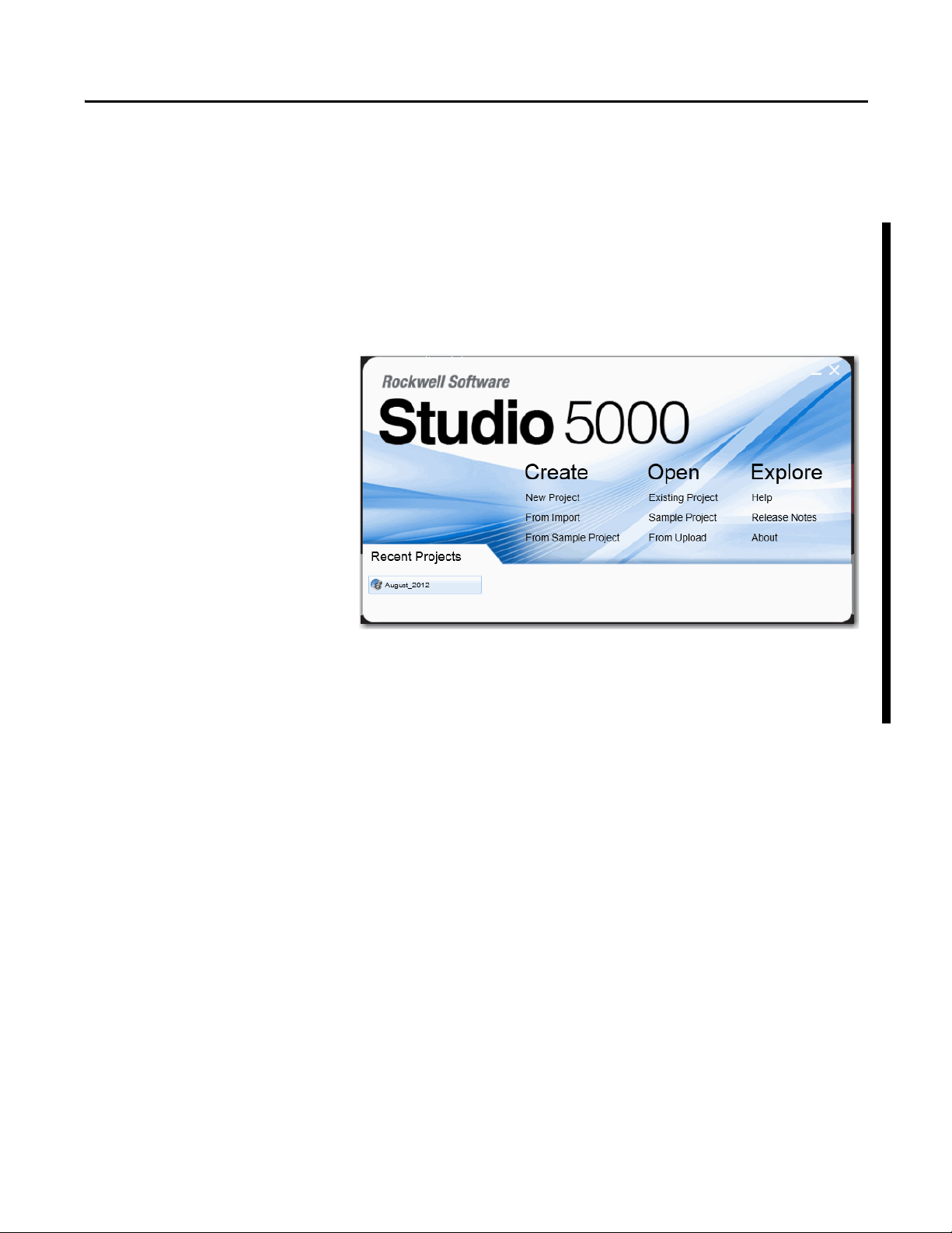
Studio 5000 Environment
The Studio 5000 Engineering and Design Environment combines engineering
and design elements into a common environment. The first element in the Studio
5000 environment is the Logix Designer application. The Logix Designer
application is the rebranding of RSLogix™ 5000 software and will continue to be
the product to program Logix5000™ controllers for discrete, process, batch,
motion, safety, and drive-based solutions.
The Studio 5000 environment is the foundation for the future of Rockwell
Automation® engineering design tools and capabilities. It is the one place for
design engineers to develop all of the elements of their control system.
Rockwell Automation Publication 1789-UM002J-EN-P - December 2012 11
Page 12
Preface
IMPORTANT
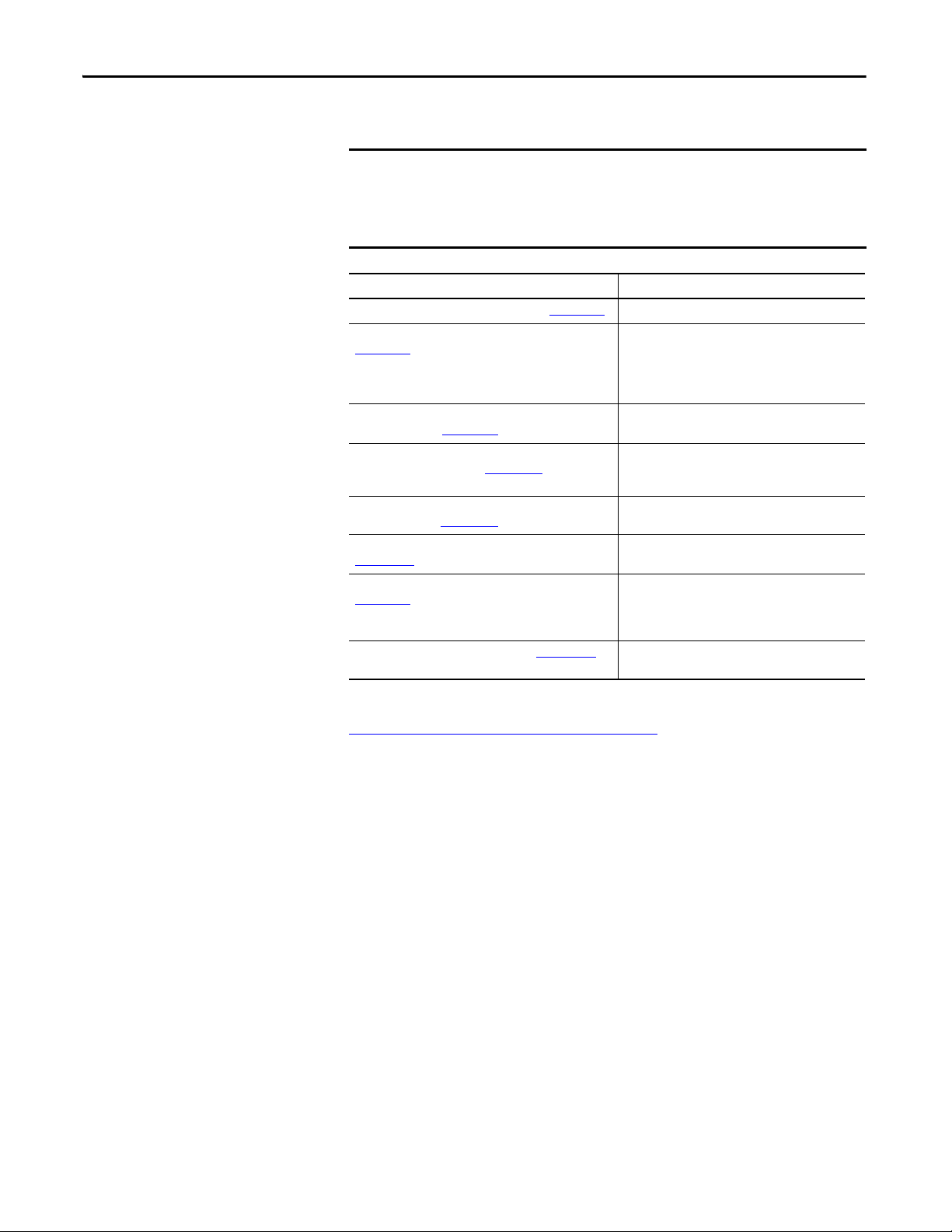
Additional Resources
These documents address the Logix5000™ family of controllers and networks.
We recommend that you read the appropriate release notes for software
requirements, compatible PCI cards and driver, and system requirements.
To locate the release notes for your system, search for 1789-RN in
Literature Library.
Resource Description
Logix5000 Controllers Quick Start, publication 1756-QS001 Explains how to set up a Logix5000 controller.
Logix5000 Controllers Common Procedures, publication
1756-PM001
Logix5000 Controllers General Instruction Set Reference
Manual, publication 1756-RM003
Logix5000 Controllers Process Control/Drives Instruction Set
Reference Manual, publication 1756-RM006
Logix5000 Controllers Motion Instruction Set Reference
Manual, publication 1756-RM007
Motion Modules in Logix5000 Control Systems, publication
LOG IX- UM0 02
EtherNet/IP Network Configuration User Manual, publication
ENET-UM001
PhaseManager™ User Manual, publication LOGIX-UM001
Describes how to complete standard tasks for
Logix5000 controllers. Program logic by using
sequential function chart (SFC), ladder diagram (LD),
structured text (ST), and function block diagram (FBD)
languages.
Program sequential applications, ladder diagram, and
structured text instructions.
Programming process control and drives applications
and function block
diagram instructions.
Describes ladder diagram motion instructions so you
can program motion applications.
Provides general information about motion modules.
Describes how to use EtherNet/IP communication
modules with your Logix5000 controller and
communicate with various devices on the Ethernet
network.
Describes how to set up a state model for your
controller.
You can view or download publications at
http:/www.rockwellautomation.com/literature/
. To order paper copies of
technical documentation, contact your local Allen-Bradley distributor or
Rockwell Automation sales representative.
12 Rockwell Automation Publication 1789-UM002J-EN-P - December 2012
Page 13
Chapter 1
IMPORTANT
SoftLogix 5800 System
Catalog Numbers 1789-L10, 1789-L30, 1789-L60
Top ic Pag e
About the SoftLogix 5800 Controller 13
Before You Begin 14
Install the SoftLogix 5800 Controller 15
FactoryTalk Activation Manager 15
Configure the RSLinx Virtual-backplane Driver 18
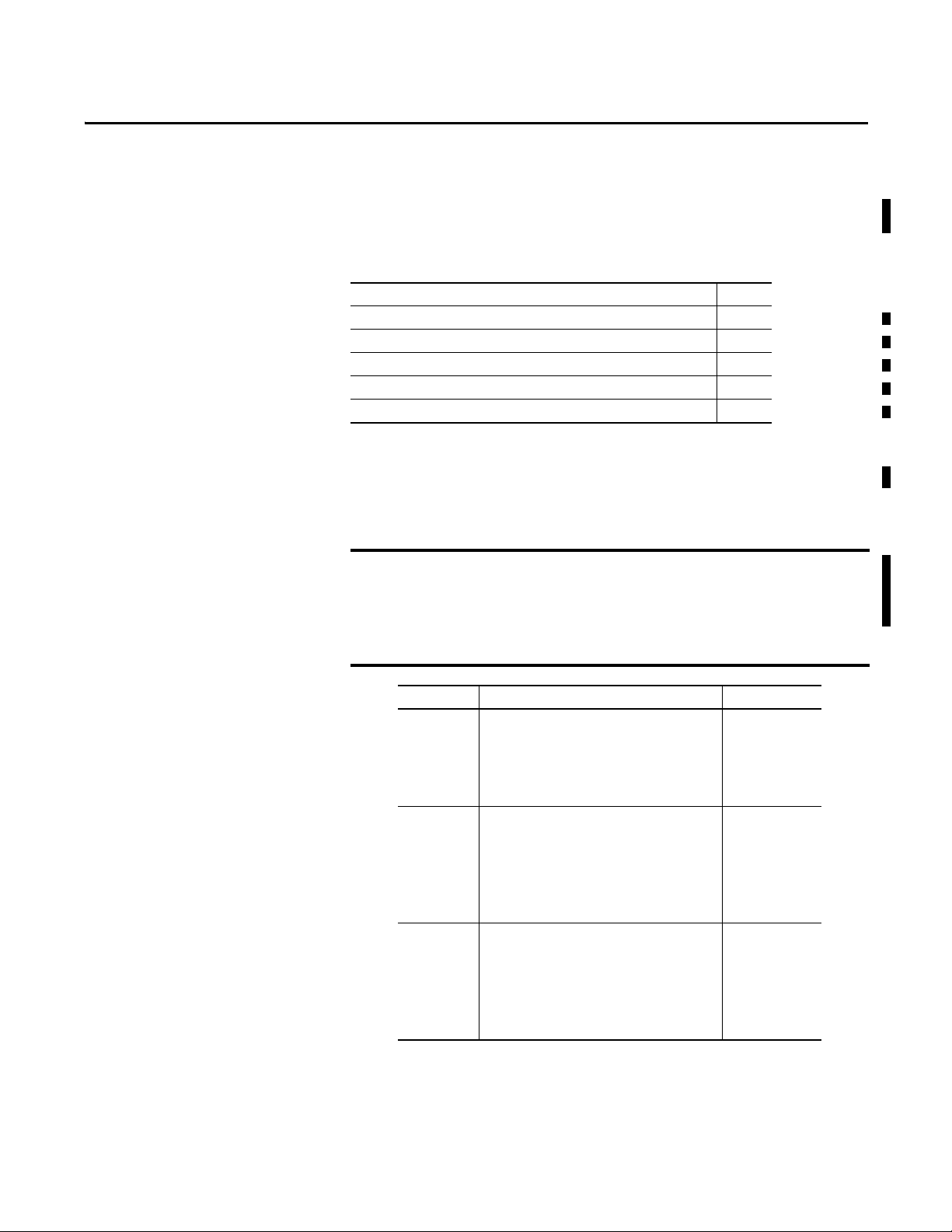
About the SoftLogix 5800 Controller
The type of SoftLogix™ 5800 controller you use determines how many slots are available in the
virtual chassis and how many devices you can install.
Motion, ControlNet, and DeviceNet modules not currently supported in SoftLogix software,
version 21.00.00 or later which runs on these 32 and 64-bit Windows operating systems:
– Win 7 Pro (32 & 64 bit)
– Win 7 Home Premium (32 & 64 bit)
– Server 2008 R2 Standard Edition w/SP1
Running the SoftLogix software in a Virtual Machine, for example, VMWare or VirtualBox, is not
supported.
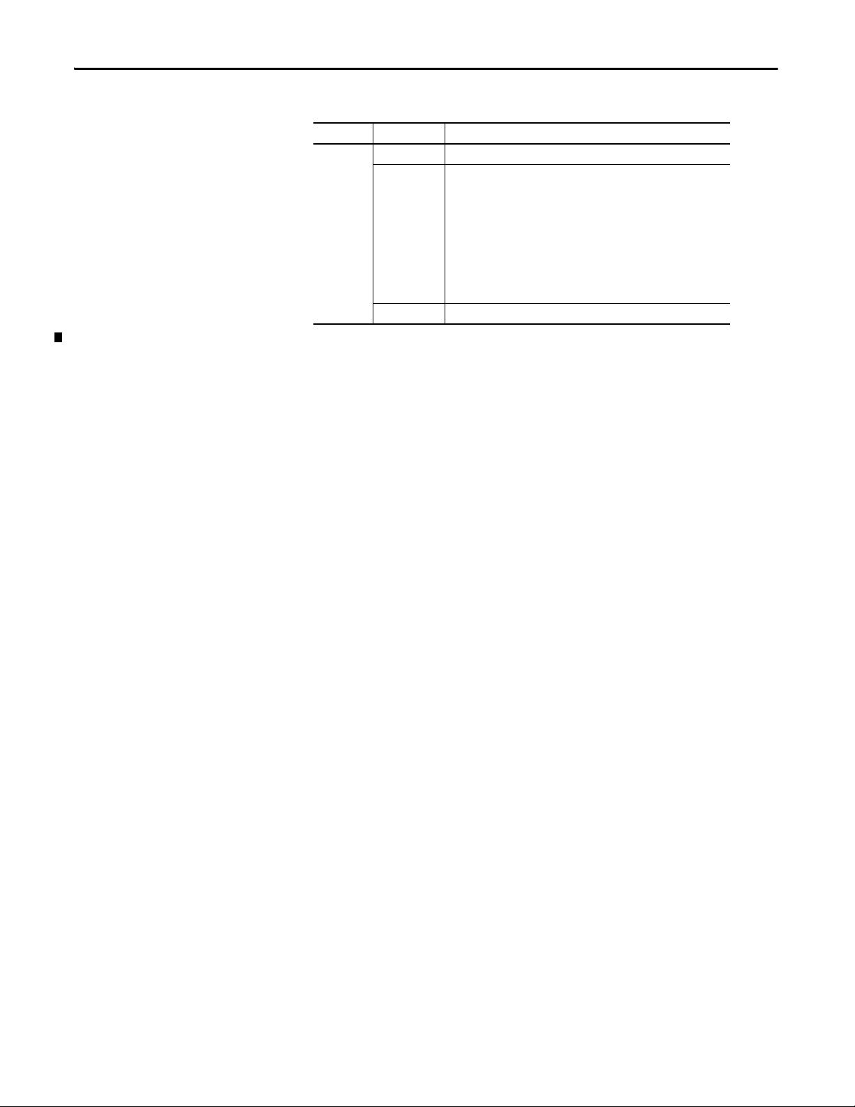
Controller Type Maximum Available Slots
1789-L10 • One SoftLogix 5800 controller
• Memory size limit of 2 MB per controller
• One 1784-SIM module
• EtherNet/IP support
• No third-party virtual-backplane module suppor t
1789-L30 • Two SoftLogix 5800 controllers
• Memory size limit of 64 MB per controller
• Five PCI network interface cards
• Five 1784-SIM modules
• EtherNet/IP support
• Third-party virtual-backplane module suppor t
1789-L60 • Six SoftLogix 5800 controllers
• Memory size limit of 64 MB per controller
• Sixteen PC I network interface cards
• Sixteen 1784-SIM modules
• EtherNet/IP support
• Third-party virtual-backplane module suppor t
(1) As of version 12 of the SoftLogix 5800 controller, the 1789-L10 controller supports three slots in the virtual chassis.
(2) The number of available slots in th e virtual chassis is limited by activation level. You can have as many PCI communication
cards as you have available slots in the virtual chassis and in the personal computer.
(2)
(2)
3-slot virtual chassis
5-slot virtual chassis
16-slot virtual chassis
(1)
Rockwell Automation Publication 1789-UM002J-EN-P - December 2012 13
Page 14

Chapter 1
IMPORTANT
IMPORTANT
IMPORTANT
IMPORTANT
SoftLogix 5800 controllers and software do not support Integrated Motion on the EtherNet/IP
network. All motion PCI cards are not suppor ted by the Softlogix software, version 20.00.00 and
later.
PCI-based cards are not supported when using the Microsoft Windows 7 operating system. The
1784-PCIDS card is not supported when using the Microsoft Windows Vista or Windows 2008
Server operating system.
Before You Begin
Make sure you have the following software installed before you install SoftLogix software:
• Windows 7 operating system
• RSLinx® Classic software
We recommend that you read the appropriate release notes for software requirements,
compatible PCI cards and driver, and system requirements.
To locate the release notes for your system, search for 1789-RN in
Literature Library at http://www.rockwellautomation.com/literature
In Microsoft Windows Vista, Windows 2008 Server, and Windows 7 operating systems, when
RSlinx software is running as a service, the RSLinx® driver configuration GUI is not available.
To invoke the RSL inx GUI, remove a ll SoftLogix controllers from the chassis monitor and use the
RSLinx Control Panel to start RSLinx software as an application instead of a service.
.
Before you can install the SoftLogix 5800 controller, you need to perform the following steps.
1. Log into the Windows operating system under an account that is a member of the
Administrators user group on the computer where you are installing the SoftLogix 5800
controller.
To log in as a member of the Administrators group, your user account must be added to the
Administrators group on the computer. Ask your system administrator if you need help.
2. Install or verify that the following Windows services, required by the SoftLogix 5800
controller, are running.
The Workstation and Server services are automatically installed when you install Windows
Networking orRemote Access Service (RAS).
A machine running SoftLogix software does not support a remote desktop.
14 Rockwell Automation Publication 1789-UM002J-EN-P - December 2012
Page 15
Chapter 1
IMPORTANT
Install the SoftLogix 5800 Controller
If you have a previous version of the SoftLogix 5800 controller already installed on the
computer, use Start>Control Panel>Programs and Features to remove that earlier version
before installing the current version.
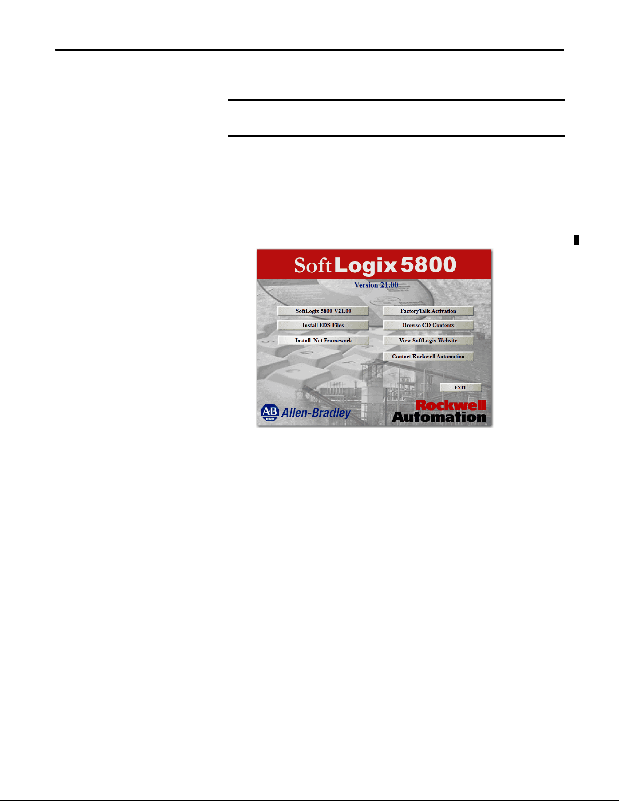
When you insert the installation DVD into your CD ROM drive, the DVD automatically begins
the set-up program for the controller. If your computer meets the hardware and software
requirements for the controller, you can install the controller.
1. If RSLinx software is already running, shut it down before beginning this installation
procedure.
2. Insert the SoftLogix 5800 installation DVD.
3. From the installation window, click SoftLogix 5800 V21.00.
4. Follow the set-up wizard.
FactoryTalk Activation Manager
There are two types of FactoryTalk® activations to activate the SoftLogix 5800 controller license—
node-locked and concurrent.
Node-locked Activation
Node-locked activation can be used only on the computer where the activation is locked (on the
personal computer for which the license was purchased). It is always locked to a specific piece of
hardware, for example, an Ethernet card, a hard disk, or a USB dongle.
Concurrent Activation
Concurrent activation is used in a server-client environment and is a type of activation that lets
multiple computers across a network use Rockwell Automation software products concurrently. A
concurrent activation can ‘float’ to, or be borrowed temporarily from, an activation server for a
specific period of time before expiring and returning automatically to the pool of available
activations on the server. Concurrent activations can be borrowed only if your Rockwell Software®
product supports borrowed activations.
If you want to check out a concurrent activation from an activation server, you do not need to use
the Rockwell Software Activation website. You can use the FactoryTalk Activation Manager to
configure your client computer to recognize the activation server computer where concurrent
activations are stored.
Rockwell Automation Publication 1789-UM002J-EN-P - December 2012 15
Page 16
Chapter 1
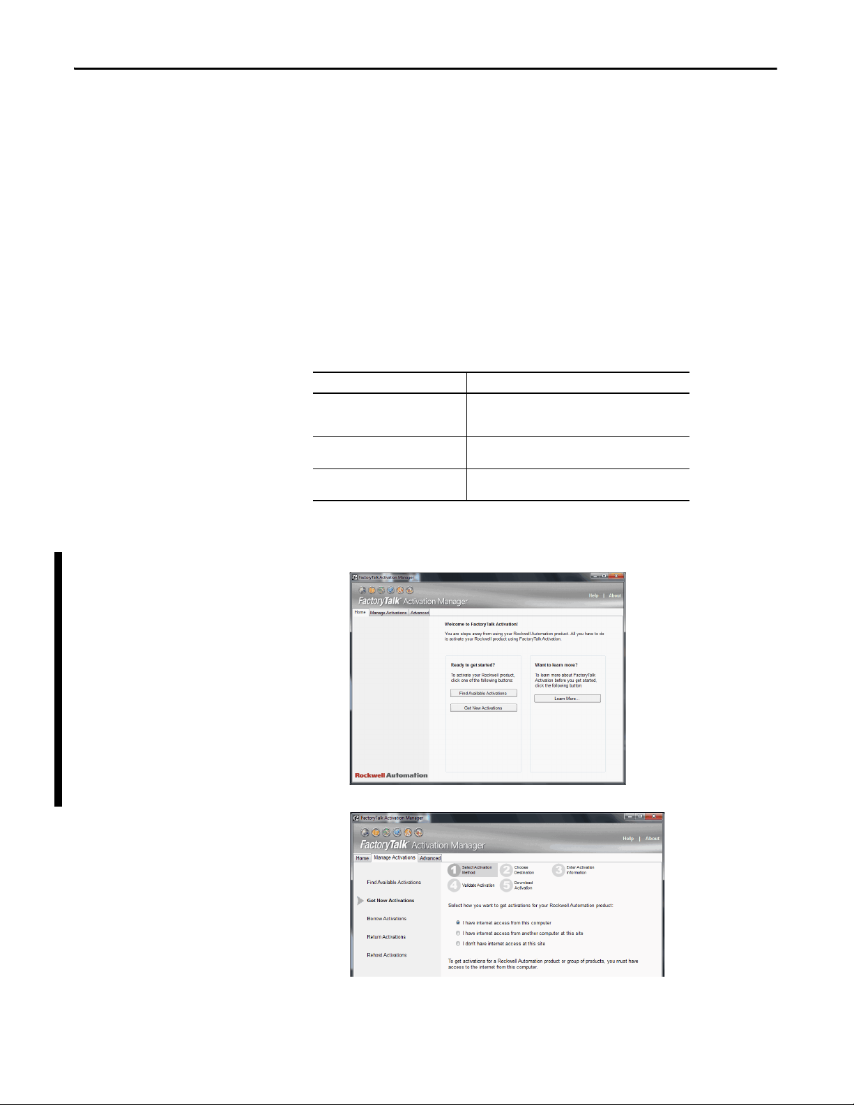
Run the FactoryTalk Activation Manager
When you install Studio 5000 environment, FactoryTalk Activation Manager is automatically
installed on the computer where the activation needs to reside. The FactoryTalk Activation
Manager software manages activations for the Rockwell Software products installed on the
computer. The FactoryTalk Activation Manager opens automatically when you install a new
Rockwell Software product.
You can also run the tool from the Windows Start menu by choosing Start>Programs>Rockwell
Software>FactoryTalk Activation>FactoryTalk Activation Manager.
For more information about the FactoryTalk Activation Manager, refer to the online help in the
software.
You need to have the following information available to activate your license:
• Host ID
• Serial Number
• Product Key
Item Description
Host ID This is found by using the FactoryTalk Activation Manager.
Serial Number This is a 10-digit number supplied to you when you purchased
Product Key This is usually found in a red envelope that is shipped with
Choose Start>Programs>Rockwell Software>FactoryTalk
Activation>FactoryTalk.
your product.
your product.
To start activation, follow these steps.
1. Click ‘Find Available Activations’ or ‘Get New Activations’.
2. Follow steps 1…5 in the FactoryTalk Activation Manager.
16 Rockwell Automation Publication 1789-UM002J-EN-P - December 2012
Page 17

Activation Tools and Rehosting
For information on Activation Tools and Rehosting Activations, see the Rockwell Software
Activation website at https://activate.rockwellautomation.com
.
Troubleshoot FactoryTalk Activations
There could be several reasons you might have trouble installing
your activations:
• If you accidentally requested too few concurrent activations for a product, you can
download more new activations for the same Host ID. You cannot download more
activations than you have purchased.
To purchase additional activations, contact your local Rockwell Automation sales office.
• If you accidentally requested too many concurrent activations for a product, you must
rehost all of the activations, and then request the correct number of activations again.
For e xample, i f you have 50 con current activatio ns avai lable for a product, and you intended
to request 10 for a particular Host ID, but accidentally selected 13 in the Activations
Requested list, you cannot return just the three activations you didn't want. You must
rehost all 13 activations, and then download 10 activations to the correct Host ID.
• If you accidentally requested activations for the wrong Host ID (computer or dongle), you
must rehost all of the activations you downloaded accidentally, and then request the
activations again for the correct Host ID.
• If you accidentally requested activations for the wrong product, you must rehost all of the
activations for that product, and then request the activations again.
For example, if you accidentally requested five concurrent activations for Logix Designer
application instead of FactoryTalk View SE software, you must rehost the five activations
for Logix Designer application, and then download five activations for FactoryTalk View
SE software.
To obtain more information, go to the Rockwell Automation Activations Support website
at https://activate.rockwellautomation.com
.
Chapter 1
Rockwell Automation Publication 1789-UM002J-EN-P - December 2012 17
Page 18
Chapter 1
IMPORTANT
Configure the RSLinx Virtual-backplane Driver
Use RSLinx software to configure the virtual-backplane driver. You do this only once for the
computer.
The RSLinx virtual-backplane driver is required for SoftLogix software to operate.
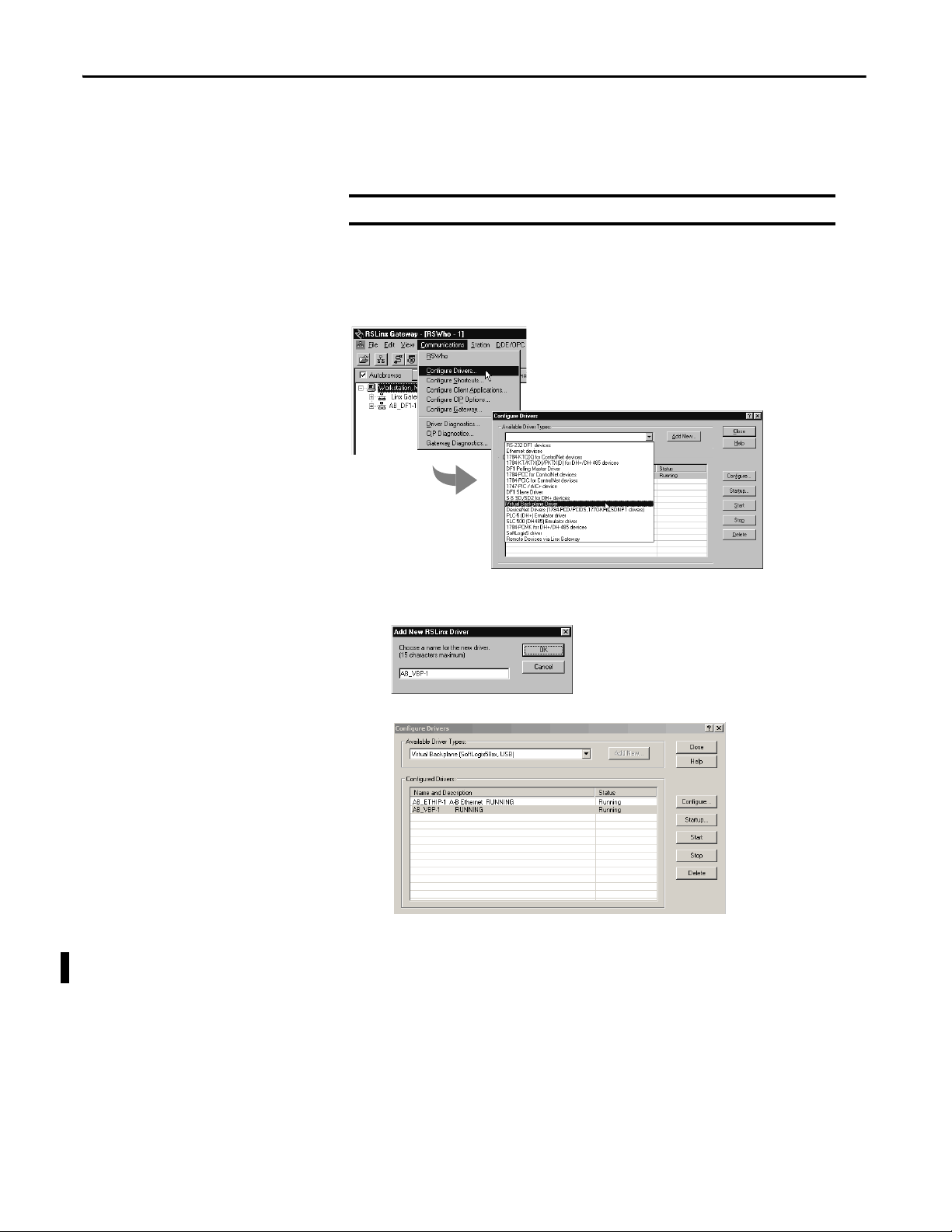
To install the virtual-backplane driver, follow these steps.
1. In RSLinx software, from the Communications menu, choose Configure Drivers.
2. From the Available Driver Type pull-down menu, choose Virtual Backplane Driver.
3. Click Add New.
4. Type the driver name, such as AB_VBP-1, and click OK.
The Configure Drivers dialog box appears.
5. Click Configure.
The Configure VirtualBackplane dialog box appears. The Logix Designer application,
version 21.00.00, lets you insert a valid SoftLogix module into slot 0.
18 Rockwell Automation Publication 1789-UM002J-EN-P - December 2012
Page 19
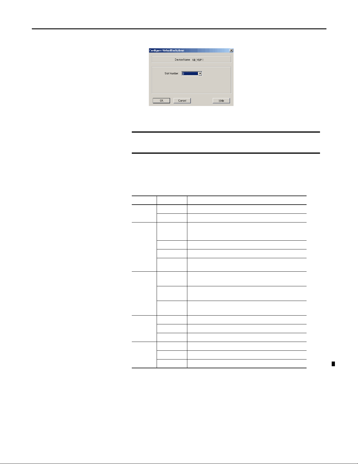
The RSLinx software module defaults in Slot 0 if not set up for another slot position.
IMPORTANT
6. From the Slot Number pull-down menu, choose a slot number.
7. Click OK and then click Close.
Even if you remotely program the controller over a ControlNet or Ethernet link, you must
add the virtual-backplane driver via RSLinx software. If you do not, the SoftLogix
application will not be restored when you restart the computer.
Troubleshoot the SoftLogix 5800 Controller
This table describes the status of the controller.
Table 1 - Troubleshooting the Controller
Chapter 1
Indicator Status Description
RUN Off The controller is in Program or Test mode.
Green The controller is in Run mode.
I/O Off Either of these is true:
Green The controller is communicating with all the devices in its I/O configuration.
Green flashing One or more devices in the I/O configuration of the controller are not responding.
Red flashing A virtual chassis error was detected. Contact your Rockwell Automation
FRC Off No tags contain force values.
Flashing At least one tag contains a force value.
Green Forces are active (enabled).
(1)
RS232
BAT
(1)
Off No COM port was selected.
Green The selected COM port was successfully assigned to channel 0 on the controller.
Red There is a COM port conflict or you selected an invalid COM port number.
Off Normal operation.
Amber flashing The controller is in Power-up mode.
Red Persistent storage for the controller has failed.
• There are no devices in the I/O configuration.
• The controller does not contain a project (controller memory is empt y).
representative or local distributor.
Forces are inactive (disabled).
Force values are inactive (disabled).
Force values may or may not exist.
Rockwell Automation Publication 1789-UM002J-EN-P - December 2012 19
Page 20
Chapter 1
Table 1 - Troubleshooting the Controller (continued)
Indicator Status Description
OK R ed flashing Recoverable fault.
Red Nonrecoverable fault.
Complete the following to correc t.
1. Remove the controller from the virtual chassis and then reinstall the
controller.
2. Download the project.
3. Place the controller in Run mode.
If the problem continues to occur, contact your Rockwell Automation sales
representative or local Allen-Bradley distributor.
Green The controller is OK.
(1) Note that these status indicators func tion slightly different than the same status indicators on a ControlLogix® controlle r.
20 Rockwell Automation Publication 1789-UM002J-EN-P - December 2012
Page 21

Chapter 2
What is the SoftLogix System?
Top ic Pag e
SoftLogix System Components 22
Set Up the Chassis Monitor 24
Configure the SoftLogix Controller 27
Developing Programs 34
How the SoftLogix System Uses Connections 38
Connections for Produced and Consumed Tags 38
Connections for Messages 38
Connections for I/O Modules 40
Total Connection Requirements 40
Restart the Controller 41
Select a System Overhead Percentage 42
This chapter discusses SoftLogix controller options and characteristics.
Procedures include how to configure your SoftLogix controller in the virtual
chassis monitor for the first time and how to create your SoftLogix project in the
Logix Designer application.
The SoftLogix system is a ‘soft’ control system that runs in Microsoft operating
systems. The system resides on a computer, as opposed to a physical module in a
hard chassis. For a list of the supported Windows operating systems, see the
System Requirements section of the current release notes. The SoftLogix
controller is part of the Logix environment and is a software-based controller that
supports Logix instructions.
Rockwell Automation Publication 1789-UM002J-EN-P - December 2012 21
Page 22

Chapter 2 What is the SoftLogix System?
SoftLogix System Components
A SoftLogix system can consist of these components, depending on your needs:
• The Chassis Monitor resides in the SoftLogix Virtual Chassis. It is a virtual
‘soft’ chassis as opposed to a physical chassis. It lets you create, delete,
monitor, and configure controllers, communication interface cards, and
motion cards in your SoftLogix System.
• The Studio 5000 environment supports every Logix controller. It provides
the flexibility to program (online or offline) in ladder logic, function block
diagram, structured text, and sequential function chart. It provides
complete axis configuration and motion programming support.
• A SoftLogix 5800 controller is based on the Logix platform and takes the
control functions normally found in a dedicated programmable controller,
encapsulates them in software, and runs them on a commercial operating
system. The SoftLogix controller contains a high-speed motion task,
which executes ladder motion commands and generates position and
velocity profile information. The controller sends this profile information
to one or more motion cards. Each controller can control up to 32 axes of
motion. There are several controllers to choose from in the SoftLogix
family, depending on your needs.
• A commercially available Ethernet port for messaging and controlling I/O
over an EtherNet/IP network.
• RSNetWorx™ software is a configuration tool that lets you control and
schedule your network. RSNetWorx software can be used with a
ControlNet network, a DeviceNet network, and an EtherNet/IP network.
• RSLinx software is a communication server that lets you configure
communication devices for networks.
• IOLinx software lets the SoftLogix controller read I/O data.
22 Rockwell Automation Publication 1789-UM002J-EN-P - December 2012
Page 23
What is the SoftLogix System? Chapter 2
Analog
Analog Drives
EtherNet/IP Connection
SoftLogix
IMPORTANT
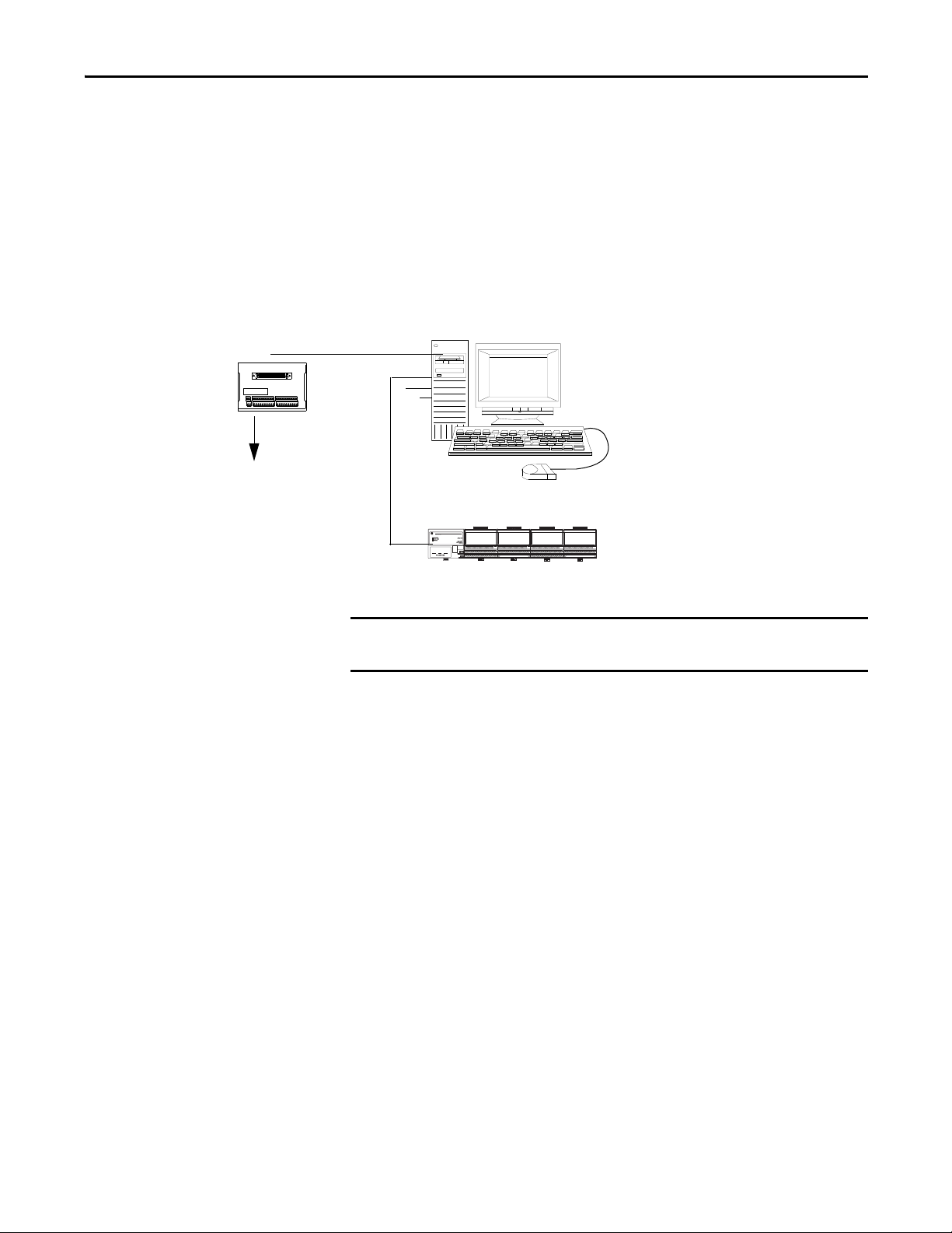
SoftLogix System Description
The same RSLogix 5000 software supports program development for all Logix
controllers. The system can make a connection through a 1784-PCICS card via
the ControlNet network, through a 1784-PCIDS card via the DeviceNet
network, and through a standard EtherNet port via the EtherNet/IP network.
SoftLogix supports two types of motion cards; the 1784-PM02AE analog
motion card and the 1784-PM16SE SERCOS motion card.
Figure 1 - The SoftLogix System at a Glance
Regardless of the product you have, choose 1789-L60/A in RSLogix 5000
software when you specify a controller type.
Rockwell Automation Publication 1789-UM002J-EN-P - December 2012 23
Page 24
Chapter 2 What is the SoftLogix System?
IMPORTANT
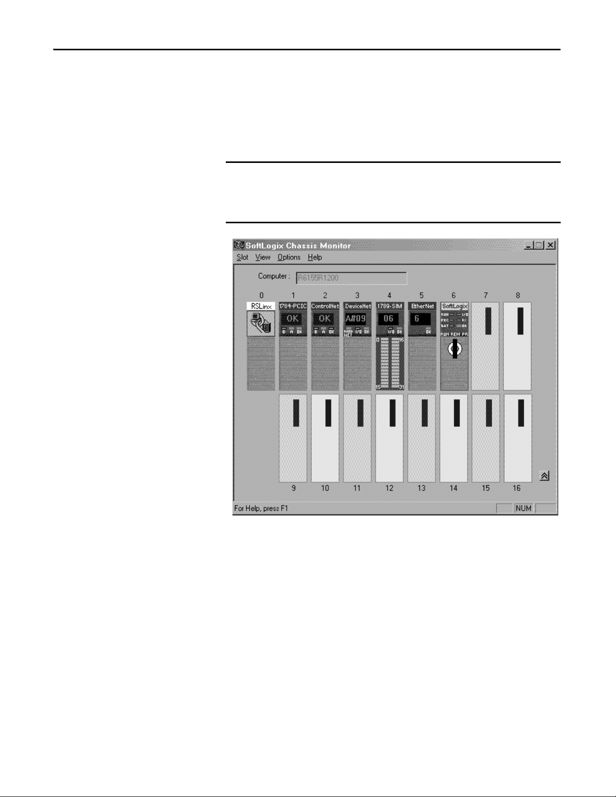
Set Up the Chassis Monitor
The Chassis Monitor is your window into the SoftLogix system that lets you
configure and monitor the system components. The Chassis Monitor models a
physical chassis, but is virtual, or ‘soft.’ You install virtual devices in the virtual
chassis to represent the controller and cards in your system.
An example of the SoftLogix Chassis Monitor is shown here.
Treat the computer running a SoftLogix controller like an industrial
controller and not a personal computer. A personal computer can perform
many operations that are incompatible with the real-time operations
required by a SoftLogix controller.
The Chassis Monitor is your SoftLogix controller interface. You use the
simulated status indicators to view the status of the controllers in your system.
You use the virtual chassis to do the following:
• Add and configure controllers
• Add and configure communication cards
• Change processor mode
• Monitor controller and associated module status
• Monitor motion performance
24 Rockwell Automation Publication 1789-UM002J-EN-P - December 2012
Page 25

What is the SoftLogix System? Chapter 2
IMPORTANT
Table 1 - Chassis Motor Characteristic
Characteristic Description
Startup mode Specify how the controller should behave when its service is star ted. Select Remote Program (default) or
Memory size Specify the memory size (KB) to allow for the controller. The maximum limit depends on the controller type. See page 25
Periodic save interval Specify whether you want to save the current controller information (tag data values and configuration information)
Continuous task dwell time (ms) Specify the dwell time (0…1000 ms) made available for all other Windows applications. The default is 10 ms.
CPU affinity If your computer has multiple Pentium CPUs, choose which CPU to use for this controller. The default is CPU 0.
Channel 0 serial port Choose which COM port to use for serial communication. Choose COM1, COM2, COM3, or COM4. The default is none.
Last Controller State.
more information.
periodically, and if so, specify how often (minutes). Specify an interval between 0.5…30 minutes. Online edits to the
program are saved instantly, regardless of Periodic Save interval. The default is enabled for 10 minutes.
See page 26
The dwell time is the time between the end of the continuous task and the start of the next execution of the continuous
task. This setting has an impact on overall system performance, see Appendix E
about this setting’s impact on overall system performance.
.
Determine a Memory Size
for
The memory size you specify is the amount of RAM in your computer that
you want to allocate to the SoftLogix controller. The maximum memory size
per controller is determined by the controller type.; see page 25
information. This allocated RAM is not available to the Windows operating
system or any other application.
These equations provide an estimate of the memory needed for a controller.
Each of these numbers includes a rough estimate of the associated user
programming. Depending on the complexity of your application, you might
need additional memory.page 22
Controller tasks _____ * 4000 = _____ bytes (min 1 needed)
Discrete I/O points _____ * 400 = _____ bytes
Analog I/O points _____ * 2600 = _____ bytes
Communication modules _____ * 2000 = _____ bytes
Motion axis _____ * 8000 = _____ bytes
Tot al = _____ bytes
If you want to change the amount of memory you specified for a controller, you
must first remove the controller from the SoftLogix chassis monitor, then
reinstall the controller and specify the new memory size.
for more
Rockwell Automation Publication 1789-UM002J-EN-P - December 2012 25
Page 26

Chapter 2 What is the SoftLogix System?
Specify a Periodic Save Interval
The periodic save task executes at a priority of ‘user-mode high’. This means that
the control process running within the SoftLogix 5800 controller will not be
impacted by a periodic save, but other user applications will be impacted if they
run at a priority lower than ‘user-mode high’. Most HMI applications run at a
‘user-mode normal’ priority. If these applications run on the same computer as
the SoftLogix 5800 controller, these applications will be starved of CPU cycles
while the periodic save is in progress. If you run an HMI application remotely
and gather data from a SoftLogix 5800 controller via OPC, the performance of
the HMI may also be impacted during a periodic save. The controller handles
both the periodic save ‘tag value upload’ and HMI OPC requests through the
same communication mechanism.
When the periodic save task executes, it performs these actions:
• For every tag defined within the controller, the current tag value is read
from the controller.
The larger the amount of data, the longer the periodic save takes and the
greater the impact on HMI responsiveness.
• The current tag values read earlier, along with the current program file, are
saved to the computer disk drive.
The larger the archive file, the longer the periodic saves takes and the
greater the impact on HMI responsiveness. However, tag data size has
more of an impact than archive file size.
To maintain better HMI responsiveness, you can do the following:
• Turn off the periodic save interval.
Even with the periodic save interval disabled, a periodic save occurs if a
remote terminal performs an upload. This makes sure that the most
current tag data values and archive file are uploaded.
If you disable the periodic save, you can still initiate a save manually by
using the Save menu item on the controller from the Chassis Monitor or
programmatically from an external routine or application.
(See Chapter 7
).
• Increase the periodic save interval so that it occurs less frequently.
• Use a dual CPU computer.
On a dual CPU computer, the Windows operating system automatically
balances the periodic save and HMI applications across the CPUs.
For more information on system tuning and the periodic save interval,
see Appendix E
26 Rockwell Automation Publication 1789-UM002J-EN-P - December 2012
.
Page 27
What is the SoftLogix System? Chapter 2
Configure the SoftLogix Controller
You must first create and configure your SoftLogix controller, that is, catalog
number 1789-L10, 1789-L30, or 1789-L60, in the virtual chassis monitor.
Step 1: Create and Configure the Controller in the SoftLogix Chassis Monitor
When you install a controller, the Chassis Monitor lets you configure specific
characteristics about the controller. To configure the controller in the Chassis
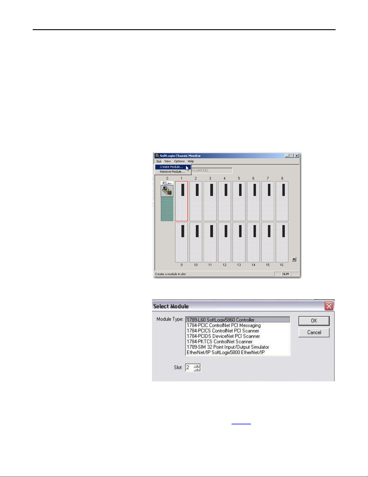
Monitor, follow these steps.
1. In the SoftLogix Chassis Monitor, from the Slot menu, choose
Create Module.
The Select Module dialog box appears.
2. In the Select Module dialog box, select your module type and enter the
Slot number.
RSLinx software defaults to slot 0, but you can move it to another slot if
set up for this functionality. See page 29
Rockwell Automation Publication 1789-UM002J-EN-P - December 2012 27
.
Page 28
Chapter 2 What is the SoftLogix System?
For this example, we will enter slot 1 for the 1789-L60
SoftLogix controller.
3. Click OK.
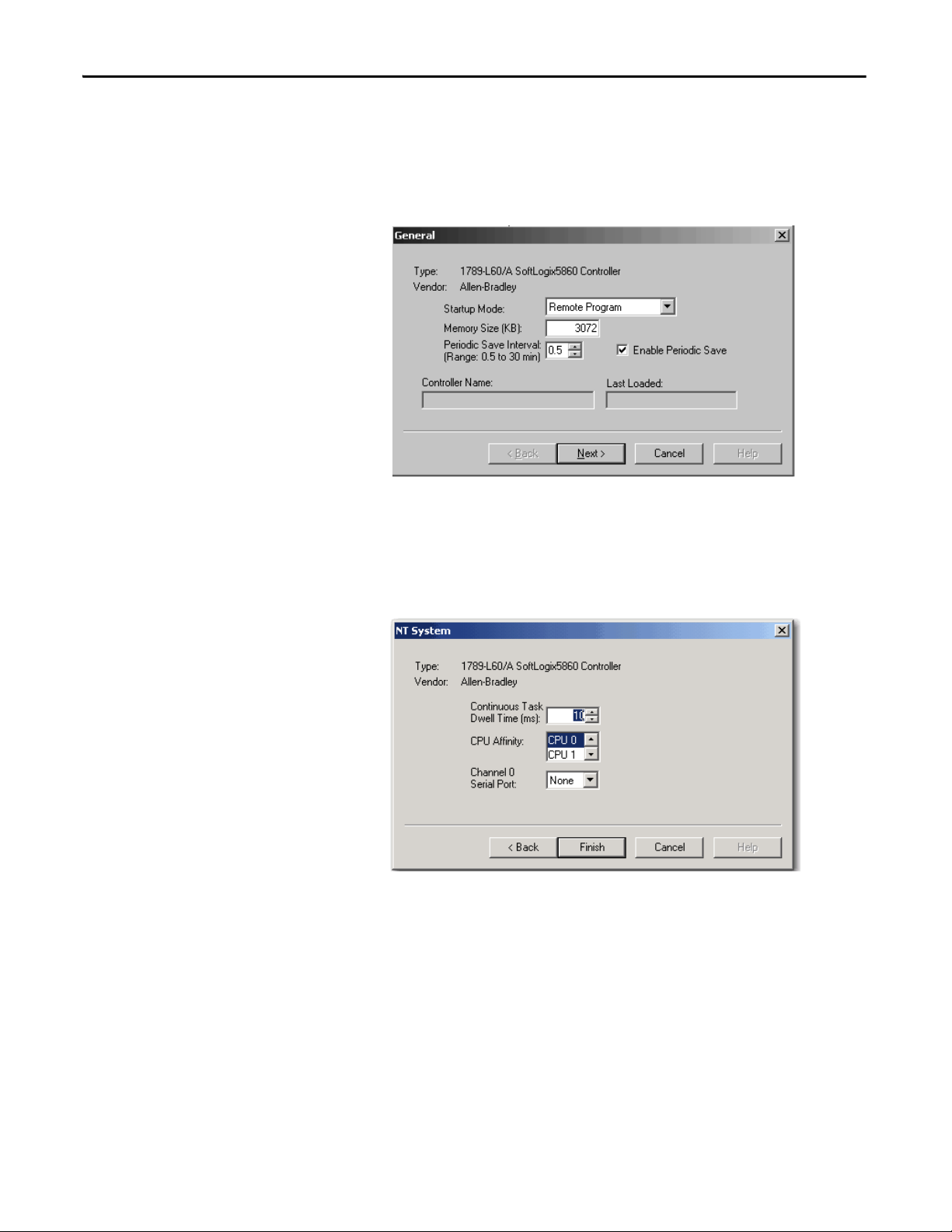
The General dialog box appears.
4. In the General dialog box, enter Startup Mode, Memory Size and Periodic
Save Interval values.
5. Click Next.
The NT System dialog box appears.
6. In the NT System dialog box, enter Continuous Task Dwell Time, CPU
Affinity, and Channel Serial Port values.
7. Click Finish.
28 Rockwell Automation Publication 1789-UM002J-EN-P - December 2012
Page 29
What is the SoftLogix System? Chapter 2
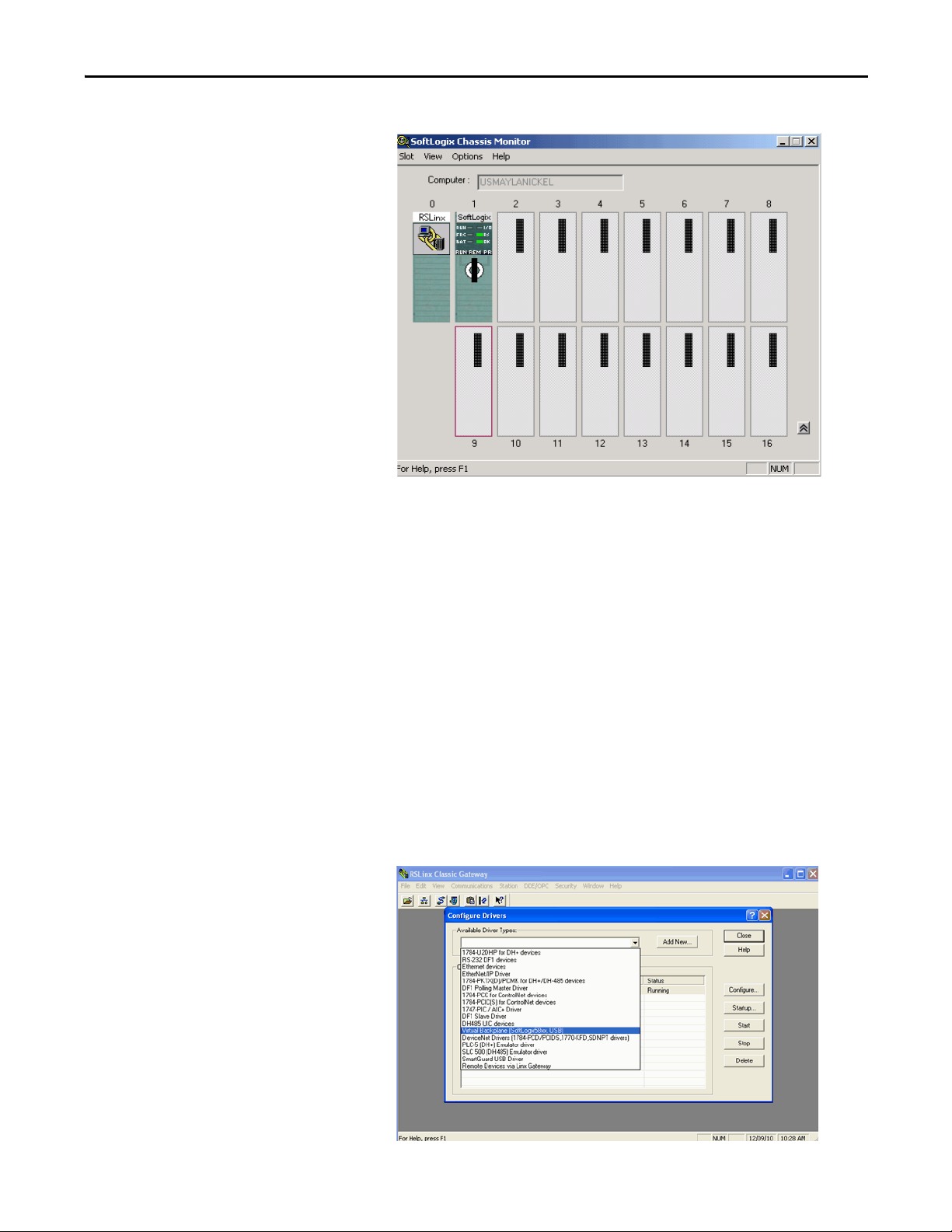
This SoftLogix Chassis Monitor now shows our new controller in slot 1.
Change the RSLinx Software Slot
The RSLinx software module automatically defaults to Slot 0 in the chassis. But
you can program the virtual backplane to use the RSLinx module in another slot
before starting up the SoftLogix application. This flexibility allows a SoftLogix
module to be used in Slot 0 if so desired.
Complete these steps to set up RSLinx software, version 2.59.00 or later, in the
chassis.
1. In RSLinx software, from the Communications menu, choose
Configure Drivers.
The Configure Drivers dialog box appears.
2. From the Available Driver Types pull-down menu, choose
Virtual Backplane.
Rockwell Automation Publication 1789-UM002J-EN-P - December 2012 29
Page 30
Chapter 2 What is the SoftLogix System?
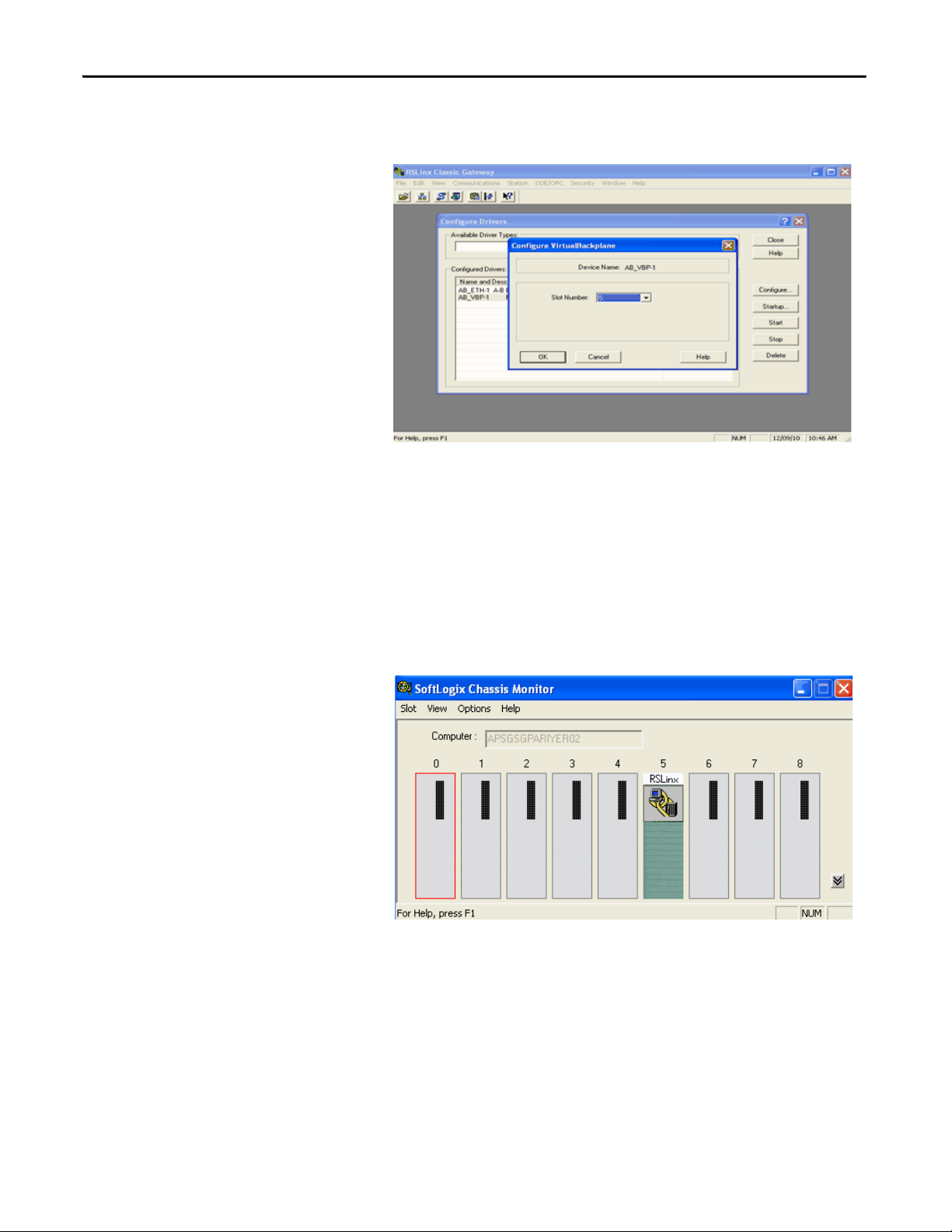
3. Click Add New and click OK.
4. Select AB-VBP-1 RSLinx Classic Driver from the list and click Configure.
The driver must be running if SoftLogix is used. If the driver is deleted
while SoftLogix is running after choosing a slot other than zero for the
RSLinx module, RSLinx chooses the next available slot in the
chassis monitor.
5. From the Slot Number pull-down menu, choose the slot for the
RSLinx module.
6. Click OK and then click Close.
This SoftLogix Chassis Monitor now shows the RSLinx module in slot 5.
In addition to configuring your controller in the SoftLogix Chassis
Monitor, you must create the controller as part of your RSLogix 5000
project before you can configure and program it.
30 Rockwell Automation Publication 1789-UM002J-EN-P - December 2012
Page 31

What is the SoftLogix System? Chapter 2
Step 2: Create the New Controller Project in RSLogix 5000 Software
1. In RSLogix 5000 software, from the File menu, choose New.
The New Controller dialog box appears.
2. In the New Controller dialog box, from the Type pull-down menu, choose
your SoftLogix controller.
3. Enter the controller Name, Chassis Type, and Slot Number to create the
new controller project.
The example above shows the 1789-L60 controller in slot 1.
For RSLogix 5000 software version 20.00.00 or later, slot 0 can
be selected.
4. Click OK.
Rockwell Automation Publication 1789-UM002J-EN-P - December 2012 31
Page 32

Chapter 2 What is the SoftLogix System?
RSLogix 5000 Controller
Organizer
You now see the new controller in the Controller Organizer’s
I/O Configuration section of RSLogix 5000 software.
Step 3: Configure the Controller in the RSLogix 5000 Project
1. To configure the controller, in the Controller Organizer, from the I/O
Configuration folder, right-click the new controller you just created and
choose Properties.
32 Rockwell Automation Publication 1789-UM002J-EN-P - December 2012
Page 33

What is the SoftLogix System? Chapter 2
The Controller Properties dialog box appears.
2. In the Controller Properties dialog box, set controller configuration
information for the open project, and when online—for the attached
controller.
The tabs that appear are particular to the type of controller you have
selected.
3. Click OK when you are done configuring each tab for your controller.
For a complete description of each tab and the appropriate configuration
settings for your SoftLogix controller, see the SERCOS and Analog
Motion Configuration and Startup User Manual,
publication MOTION-UM001.
Rockwell Automation Publication 1789-UM002J-EN-P - December 2012 33
Page 34

Chapter 2 What is the SoftLogix System?
Figure 2 - Control Application
Controller Fault Handler
Tas k 32
Tas k 1
Confi guration
Status
Watc hdo g
Program 32
Program 1
Main Routine
Fault Ro utine
Program (local)
Tag s
Other Routines
Controller (global) Tags I/O Data System-shared Data
Developing Programs
The controller’s execution model is a preemptive, multitasking system that is
IEC 1131-3 compliant. This environment provides the following:
• Tasks to configure controller execution
• Programs to group data and logic
• Routines to encapsulate executable code written in a single
programming language
Configuring Tasks
A task provides scheduling and priority information for a set of one or more
programs. You can configure tasks as either continuous or periodic. The
SoftLogix controller supports as many as 32 tasks, only one of which can
be continuous.
A task can have as many as 32 separate programs, each with its own executable
routines and program-scoped tags. Once a task is activated, all of the programs
assigned to the task execute in the order in which they are grouped. Programs can
appear only once in the Controller Organizer and cannot be shared by
multiple tasks.
34 Rockwell Automation Publication 1789-UM002J-EN-P - December 2012
Page 35

What is the SoftLogix System? Chapter 2
Setting Task Priorities
Each task in the controller has a priority level. The controller uses the priority
level to determine which task to execute when multiple tasks are triggered. There
are 3 configurable priority levels for periodic tasks that range from 1…3, with 1
being the highest priority and 3 being the lowest priority. A higher priority task
will interrupt any lower priority task. The continuous task has the lowest priority
and is always interrupted by any periodic task.
The continuous-task dwell time determines how much time to allow for other
Windows programs, running at a normal priority, to execute. The dwell time is
the time between the end of the continuous task and the start of the next
execution of the continuous task. The dwell time does not affect periodic tasks.
Periodic tasks execute as scheduled, regardless of the dwell time. By default, the
dwell time is 10 ms. This setting has an impact on overall system performance,
see Appendix E
.
Tasks Based on Other Events
The SoftLogix controller supports an additional Windows event trigger. This
trigger lets you monitor Windows events in Windows 2000 or Windows XP
operating systems so that applications outside of the SoftLogix controller can
cause a task within the SoftLogix controller to execute. For more information,
see Chapter 7
.
Rockwell Automation Publication 1789-UM002J-EN-P - December 2012 35
Page 36

Chapter 2 What is the SoftLogix System?
Tas k 1
Tas k 2
Continuous
Tas k
Dwell
Time
Table 2 - Task Execution Order for Application with Periodic Tasks and Continuous Task
Task Priority Level Task Type Actual Execution Time Worst Case
1 1 20 ms periodic task 2 ms 2 ms
2 2 10 ms periodic task 4 ms 6 ms
N/A None (lowest) Continuous task 25 ms 35 ms
N/A None Dwell time 10 ms 14 ms
Execution Time
Tas k De scr ipt ion
A The highest priority task interrupts all lower priority tasks.
B A lower priority task can be interrupted multiple times by a higher priority task.
C The continuous task runs at the lowest priority and is interrupted by all other tasks.
D The dwell time starts when the continuous task completes. The dwell time does not affect periodic tasks.
Periodic tasks execute as scheduled, regardless of the dwell time.
E The continuous t asks restart, when the dwell time completes, unless a higher priority task is running.
Determining Programs
Each program contains program tags, a main executable routine, other routines,
and an optional fault routine. Each task can schedule as many as 100 programs
(including equipment phases).
The scheduled programs within a task execute to completion from first to last.
Programs that are not attached to any task appear as unscheduled programs. You
must specify (schedule) a program within a task before the controller can scan
the program.
36 Rockwell Automation Publication 1789-UM002J-EN-P - December 2012
Page 37

What is the SoftLogix System? Chapter 2
Supporting Routines
A routine is a set of logic instructions in a single programming language, such as
ladder logic. Routines provide the executable code for the project in a controller.
A routine is similar to a program file or subroutine in a PLC or SLC™ processor.
Each program has a main routine. This is the first routine to execute when the
controller triggers the associated task and calls the associated program. Use logic,
such as the JSR instruction, to call other routines.
You can also specify an optional program-fault routine. The controller executes
this routine if it encounters an instruction-execution fault within any of the
routines in the associated program.
The SoftLogix controller supports routines developed with the relay ladder and
function block editors of RSLogix 5000 software. You can edit relay ladder and
function block routines either offline or online. You can also develop C/C++
routines and incorporate them into your project.
See Chapter 5
Chapter 6
for information on adding external routines to a project; see
for information on developing external routines.
Instruction Execution
When performing a math operation, the SoftLogix controller handles INT to
REAL conversions differently than hardware-based Logix controllers. The
SoftLogix controller completes the math operation by using the INT data and
then converts the result to REAL data, which is more consistent with how math
operations occur on personal computers. The hardware-based Logix controllers
first convert INT data to REAL data and then perform the math operation.
The SoftLogix controller also handles the conversion of single-float values to
double-float values differently than the ControlLogix controller. The personal
computer processor calculates conversions to more decimal points than the
ControlLogix controller. This can result in instructions operating differently
between SoftLogix and ControlLogix controllers. For example, when calculating
cam (MAPC) position with the MAPC instruction, the.PC bit can get set
slightly sooner or later in a ControlLogix controller than in a SoftLogix
controller. Factors that affect the time the .PC bit is set are as follows:
• Direction of travel
• Axis scaling constants of the two axes being used for the camming
instruction
• The start and end point values used in the cam
Rockwell Automation Publication 1789-UM002J-EN-P - December 2012 37
Page 38

Chapter 2 What is the SoftLogix System?
How the SoftLogix System Uses Connections
Connections for Produced and Consumed Tags
The SoftLogix system uses a connection to establish a communication link
between two devices. Connections can be any of the following:
• Controller to local I/O modules or local communication modules
• Controller to remote I/O or remote communication modules
• Controller to remote I/O (rack-optimized) modules
• Produced and consumed tags
• Messages
You indirectly determine the number of connections the controller uses by
configuring the controller to communicate with other devices in the system.
Connections are allocations of resources that provide more reliable
communication between devices than unconnected messages.
The SoftLogix controller supports the ability to produce (multicast) and
consume (receive) system-shared tags. System-shared data is accessible by
multiple controllers over an EtherNet/IP network. Produced and consumed tags
each require scheduled connections.
Tag Type Required Connection
Produced By default, a produced tag allows two other controllers to consume the tag, which means that as
many as two controllers can simultaneously receive the tag data. The local controller (producing)
must have one connection for the produced tag and the first consumer and one more connection
for each additional consumer (heartbeat). The default produced tag requires two connections.
As you increase the number of controllers that can consume a produced tag, you also reduce the
number of connections the controller has available for other operations, like communication and I/
O.
Consumed Each consumed tag requires one connection for the controller that is consuming the tag.
The SoftLogix controller supports a maximum of 127 consumed connections.
For two controllers to share produced or consumed tags, both controllers must be
attached to the same network. You cannot bridge produced and consumed tags
between two networks.
Connections for Messages
38 Rockwell Automation Publication 1789-UM002J-EN-P - December 2012
Messages transfer data to other devices, such as other controllers or operator
interfaces. Some messages use unscheduled connections to send or receive data.
These connected messages can leave the connection open (cache) or close the
Page 39

What is the SoftLogix System? Chapter 2
connection when the message is done transmitting. This table shows which
messages use a connection and whether you can cache the connection.
Message Type Communication Method Connection
CIP data table read or write CIP
PLC-2®, PLC-3®, PLC-5®, or SLC (all types) CIP
CIP with source ID
DH+™
CIP generic N/A
Connected messages are unscheduled connections on both ControlNet and
EtherNet/IP networks.
If a message executes repeatedly, cache the connection. This keeps the connection
open and optimizes execution time. Opening a connection each time the message
executes increases execution time.
If a message executes infrequently, do not cache the connection. This closes the
connection upon completion of the message, which frees up that connection for
other uses.
Each message uses one connection, regardless of how many devices are in the
message path. To conserve connections, you can configure one message to read
from or write to multiple devices.
You can cache as many as 16 messages (a combination of any type, not including
block-transfer) at one time. If you try to cache more than 16, the controller
determines the 16 most-currently used messages and caches those. If there are 16
messages cached, and a message is triggered that is currently not cached, the
controller drops the connection of the oldest-cached message to make room for
the new message.
In addition to 16 cached messages, you can also cache as many as 16 blocktransfer messages. The same conditions apply to caching block-transfer messages
as described above for caching other types of messages.
Rockwell Automation Publication 1789-UM002J-EN-P - December 2012 39
Page 40

Chapter 2 What is the SoftLogix System?
Connections for I/O Modules
Connection Description
Direct A direct connection is a real-time, data transfer link between the controller and an I/O module. The controller maintains and
Rack-optimized For digital I/O modules, you can choose rack-optimized communication. A rack-optimized connection consolidates
The SoftLogix system uses connections to transmit I/O data. These connections
can either be direct connections or rack-optimized connections.
monitors the connection between the controller and the I/O module. Any break in the connection, such as a module fault or
the removal of a module while under power, causes the controller to set fault status bits in the data area associated with the
module.
connection usage between the controller and all of the digital I/O modules on a rack (or DIN rail). Rather than having
individual, direct connections for each I/O module, there is one connection for the entire rack (or DIN rail).
To conserve the number of connections that are available, place digital
I/O modules together in the same location and use a rack-optimized connection.
To choose a rack-optimized connection, choose a ‘rack-optimized’ option for the
communication format when you add the communication device and
I/O modules to the controller project in RSLogix 5000 software.
If you have analog I/O modules, or want a direct connection to specific
I/O modules, you do not have to create the rack-optimized connection to the
communication device. To use direct connections to I/O modules, choose ‘none’
for the communication format of the communication device.
Total Connection Requirements
Table 3 - Connections
Connection Type Device Quantity Connections Per
Remote EtherNet/IP communication device (such as a 1794-AENT or 1756-ENBT
module):
• Configured as a direct (none) connection
• Configured as a rack-optimized connection
Remote I/O device over the EtherNet/IP network (direct connection) 1
Produced and consumed tag:
• Produced tag and one consumer
• Each additional consumer
Consumed tag 1
Cached message 1
Total
The SoftLogix controller supports 250 connections. Each 1784-PCICS
ControlNet communication card supports 128 total connections, 127 of which
can be scheduled. Do not configure more connections than the controller can
support. Use this table to tally ControlNet connections.
Total Connections
Device
0
1
1
1
40 Rockwell Automation Publication 1789-UM002J-EN-P - December 2012
Page 41

What is the SoftLogix System? Chapter 2
Restart the Controller
You restart the controller by either of these methods:
• Restarting the computer
• Removing and reinserting the controller in the virtual chassis
After restarting the controller, you must upload or download from
RSLogix 5000 software before you can go online with the controller. This is
because the RSLogix 5000 project file (.ACD) contains explicit knowledge of the
physical memory addresses used by the controller. When you restart the
controller, all of the physical addresses for the controller are regenerated. Note
that as long as the controller is not restarted, you can go online and offline as
many times as required.
Online with the Controller
You must save the RSLogix 5000 project after a download completes, or you will
not be able to go online with the controller. After downloading, the physical
address information has changed. RSLogix 5000 software prompts you to save
and indicates that a change has occurred even though you might not have made
changes to the project. Saving the project stores the physical address information
into the ACD file.
An upload recovers all of the information that was downloaded to the controller,
including documentation. This is because of the persistent storage feature that
you enable by specifying a periodic save interval (see page 26
the persistent storage copies the entire project file to the controller. The
controller opens and goes online with the project file so that any edits made by
RSLogix 5000 workstations are saved into the persistent image (the controller's
copy of the project file). Online edits are saved to the persistent image
immediately; tag data values are saved to the persistent image at every periodic
save interval (10 min default). If the periodic save is disabled, tag data values are
not saved, but online edits are still saved to the persistent image.
The SoftLogix controller maintains a change log that holds 999 entries. This
means that as you edit an RSLogix 5000 project file, you must save the project file
before you make 999 changes. If you make more than 999 changes to a project,
you will not be able to go back online without performing an upload or
a download.
). On a download,
Upload to the Controller
If your project has edits and you want to upload the project to the controller,
RSLogix 5000 software prompts you to save the project before uploading.
Regardless of your choice, the edits are saved before the upload occurs. This
happens because the edits are already stored in the controller as you make
the edits.
Rockwell Automation Publication 1789-UM002J-EN-P - December 2012 41
Page 42

Chapter 2 What is the SoftLogix System?
Select a System Overhead Percentage
The Controller Properties dialog box lets you specify a percentage of controller
time (excluding the time for periodic tasks) that is devoted to communication
and background functions.
1. In the RSLogix 5000 software, from the Controller Organizer, right-click
the controller and choose Properties.
2. Click the Advanced tab.
3. In the System Overhead Time Slice box, enter a percentage.
The system overhead function interrupts the continuous task. The percentage
you specify determines the amount of the continuous task to allocate to system
overhead functions, which include the following:
• Communicating with programming and HMI devices (such as
RSLogix 5000 software)
• Responding to messages
• Sending messages, including block-transfers
• Re-establishing and monitoring I/O connections (such as RIUP
conditions); this
during program execution
• Bridging communication from one communication device to another
communication device across the virtual chassis
This function allows the controller to take care of communication requests that
occur from other controllers or from queued requests from within the controller’s
application program. If communication is not completing fast enough, increase
the system overhead percentage.
Because the SoftLogix controller runs natively on your computer's Pentium CPU,
the default setting of 10% yields satisfactory performance for most applications.
does not include normal I/O communication that occurs
42 Rockwell Automation Publication 1789-UM002J-EN-P - December 2012
Page 43

Chapter 3
Communicate with Devices on an Ethernet Network
Top ic Pag e
Configure Your System for an Ethernet Network 43
Multiple EtherNet/IP Modules 54
Controller Connections over the EtherNet/IP Network 55
Distributed Ethernet I/O 56
Add a Remote Controller 60
Check EtherNet/IP Statistics 63
Example 1: Workstation Remotely Connected to a SoftLogix Controller 65
Example 2: Send Messages over the EtherNet/IP Network 68
Example 3: Send Messages over the EtherNet/IP Network to a PLC-5 Processor 71
Example 4: Control Distributed I/O 73
Configure Your System for an Ethernet Network
This chapter explains how to communicate with a device on an Ethernet network
by using the SoftLogix controller.
For information about communicating with EtherNet/IP devices, see the
EtherNet/IP Network Configuration User Manual, publication ENET-UM001
For the SoftLogix controller to operate on an EtherNet/IP network, you need
the following:
• A computer where the SoftLogix controller resides enabled with an
Ethernet communication port
• RSLogix 5000 software installed
• A computer where the RSLogix 5000 software resides enabled with an
Ethernet communication port
• RSLinx software installed
You can use any commercially-available Ethernet port. Use the Ethernet driver
that comes with the device.
.
Rockwell Automation Publication 1789-UM002J-EN-P - December 2012 43
Page 44

Chapter 3 Communicate with Devices on an Ethernet Network
Step 1: Disable UDP Messages in RSLinx Classic Software
To send messages, or control I/O, you must change the RSLinx Classic
configuration so that it does not accept UDP messages.
(1)
1. Launch RSLinx software on the computer with the controller.
2. From the View menu and choose Options.
The Options dialog box appears.
3. On the General tab, clear ‘Accept UDP Messages on the Ethernet Port’.
4. Click OK.
5. Restart your computer.
(1) RSLinx Enterprise software may have other requirements. For details, see the MySupport Knowledgebase
at http://www.rockwellautomation.com/support.
44 Rockwell Automation Publication 1789-UM002J-EN-P - December 2012
Page 45

Communicate with Devices on an Ethernet Network Chapter 3
Disabling the UDP option
Disabling the UDP option lets RSLinx software and the SoftLogix 5800
EtherNet/IP functionality coexist on the same personal computer. Disabling the
UDP option also disables RSLinx software’s Gateway functionality. RSLinx
software still functions, but the Gateway options are removed while RSLinx
software continues to display that it has a full Gateway activation. This affects
how remote computers can browse through a local computer with UDP disabled.
If UDP is disabled on a local computer, a remote computer browsing through the
local computer has this functionality:
• If the local computer has a DeviceNet module in the virtual chassis, you
cannot remotely browse the DeviceNet network. Replacing RSLinx Lite
with RSLinx Gateway software on the local or remote computer does not
enable remote browsing of the DeviceNet network.
• If the local computer has a ControlNet module in the virtual chassis, you
can remotely browse the ControlNet network.
• If the local computer has a SoftLogix controller in the virtual chassis, you
can browse the serial port of the computer.
• If the local computer has an EtherNet/IP module in the virtual chassis, you
can browse the EtherNet/IP network configured to that module.
• The local computer supports a remote connection to the SoftLogix
controller over an Ethernet network so that you can remotely program the
SoftLogix controller.
Rockwell Automation Publication 1789-UM002J-EN-P - December 2012 45
Page 46

Chapter 3 Communicate with Devices on an Ethernet Network
If UDP is disabled on a local computer, you can browse the ControlNet and
EtherNet/IP networks and serial devices to see configured devices, as long as the
appropriate module is installed in the virtual chassis on the local computer.
To be able to browse DeviceNet networks, RSLinx Gateway functionality (and
therefore UDP) must be enabled on the computer that hosts the DeviceNet
communication card.
Enabling the UDP option
Enabling the UDP option lets the RSLinx Gateway functionality operate as
expected. Installing a SoftLogix 5800 EtherNet/IP module into a system with the
UDP option enabled and RSLinx Gateway functionality enabled, causes the
SoftLogix EtherNet/IP module to display a red X in the chassis monitor. This
does not affect the operation of the RSLinx software. It does prohibit the
SoftLogix controller from sending and receiving messages and controlling
I/O modules via an EtherNet/IP network.
Adding multiple Ethernet modules does not affect controller operation when
UDP is enabled. Checking the Enable UDP box applies to all Ethernet ports on
the computer; RSLinx Gateway software will use all of the Ethernet ports.
Enable the UDP option and the RSLinx Gateway functionality when you need
the computer to configure or commission ControlNet and DeviceNet networks
and devices. With the UDP option enabled, you have this functionality and loss
of functionality in the computer where the controller resides:
• You must browse from the 1784-PCIDS driver in RSLinx software to
browse a DeviceNet network.
• You can remotely browse the ControlNet network if there is a
ControlNet module in the virtual chassis.
• You can browse over the serial port of the computer if there is a
SoftLogix controller in the virtual chassis.
• You can remotely program the SoftLogix controller because the local
computer supports a remote connection to the SoftLogix controller over
an Ethernet network.
• If there is an EtherNet/IP module in the virtual chassis, it will not function
as expected. You cannot control I/O or send messages.
• You can remotely program the SoftLogix controller because the local
computer supports a remote connection to the SoftLogix controller over
an Ethernet network.
46 Rockwell Automation Publication 1789-UM002J-EN-P - December 2012
Page 47

Communicate with Devices on an Ethernet Network Chapter 3
If you want the UDP option enabled, you should also enable the Gateway
functionality within RSLinx Gateway software. You must have RSLinx Gateway
software to enable Gateway functionality. Follow these steps.
1. Launch RSLinx software on the computer with the controller.
2. From the Communications menu, choose Configure Gateway.
The Configure RSLinx Gateway dialog box appears.
3. Check Enable RSLinx Gateway.
4. Click OK.
In many applications, initially leave UDP enabled so that you can configure
ControlNet and DeviceNet networks. After configuration is done, disable UDP
so the SoftLogix controller can have EtherNet/IP functionality. If you change the
UDP setting, you must restart RSLinx software for the change to take affect. To
restart RSLinx software, restart the computer.
For information on adding multiple Ethernet modules, see page 54
Rockwell Automation Publication 1789-UM002J-EN-P - December 2012 47
.
Page 48

Chapter 3 Communicate with Devices on an Ethernet Network
Step 2: Create the Communication Card in the SoftLogix Chassis Monitor
Add the EtherNet/IP module to the SoftLogix virtual chassis if you are
controlling I/O or sending messages over Ethernet network. These instructions
show a a SoftLogix controller installed already in slot 4. Follow these steps to add
an EtherNet/IP module to your chassis.
1. In the SoftLogix Chassis Monitor, from the Slot menu, choose Create
Module.
Or right-click the appropriate slot and choose Create.
The Select Module dialog box appears.
2. In the Select Module dialog box, select the EtherNet/IP SoftLogix 5800
EtherNet/IP communication module.
3. Enter the backplane slot number.
For RSLogix 5000 software, version 20.00.00 or later, you can specify any
slot number for the communication card, as long as the RSLinx software
module is positioned in a slot other than its default 0. See page 29
4. Click OK.
.
48 Rockwell Automation Publication 1789-UM002J-EN-P - December 2012
Page 49

Communicate with Devices on an Ethernet Network Chapter 3
10.88.94.12 255.255.252.0 10.88.92.1 00:13:2 0:03:C1:1E
The Select Device dialog box appears.
5. Select the serial number of the port you want.
If you previously had an Ethernet port configured in this slot, the chassis
monitor remembers the configuration of that previous port.
6. Click Next.
The Module Properties General dialog box appears.
7. Specify a label name for the EtherNet/IP I/O Module Marquee.
The IP address, status, and the label name you enter here scrolls across the
front of the module.
8. Click Finish.
Rockwell Automation Publication 1789-UM002J-EN-P - December 2012 49
Page 50

Chapter 3 Communicate with Devices on an Ethernet Network
This chassis monitor has an EtherNet/IP module
installed in slot 3.
This chassis monitor shows the selected IP address as a virtual module in the
SoftLogix chassis.
Step 3: Configure the Communication Card as Part of the Project
If you want to control I/O over an EtherNet/IP network, use RSLogix 5000
software to add the SoftLogix 5800 EtherNet/IP module to your project.
You should already have added the SoftLogix controller to the project.
See Step 2: Create the New Controller Project in RSLogix 5000 Software on
page 31,
Your controller is offline.
1. In the RSLogix 5000 software project, right-click the Ethernet module in
the I/O Configuration folder, and choose New Module.
50 Rockwell Automation Publication 1789-UM002J-EN-P - December 2012
Page 51

Communicate with Devices on an Ethernet Network Chapter 3
The Select Module dialog box appears.
2. Expand the Communications list and choose the 1756-EWEB/A module.
3. Click OK.
The Select Major Revision dialog box appears.
4. From the Major Revision pull-down menu, choose the revision number
and click OK.
Rockwell Automation Publication 1789-UM002J-EN-P - December 2012 51
Page 52

Chapter 3 Communicate with Devices on an Ethernet Network
The Module Properties dialog box appears.
5. Name the module, enter the IP address, and select the
Disable Keying option.
6. Click OK.
The Module Properties dialog box appears.
52 Rockwell Automation Publication 1789-UM002J-EN-P - December 2012
Page 53

Communicate with Devices on an Ethernet Network Chapter 3
Step 4: Configure the SoftLogix EtherNet/IP Module to Communicate on an Ethernet Network
Configuring a SoftLogix 5800 EtherNet/IP module is similar to configuring a
1756-ENBT module in a ControlLogix project, except for these differences:
• If the SoftLogix 5800 EtherNet/IP module is in the same virtual chassis as
the SoftLogix controller, you do not have to enter an IP address. The
configuration defaults to the IP address of the computer.
• If there are multiple IP addresses, or if the SoftLogix 5800 EtherNet/IP
module is not in the same virtual chassis as the SoftLogix controller, you
must enter an IP address. This is similar to configuring a
1756-ENBT module.
• A 1756-ENBT module requires that you choose a communication format.
This is not required for a SoftLogix 5800 EtherNet/IP module.
Refer to the EtherNet/IP Network Configuration User Manual,
publication ENET-UM001,
1756-ENBT module. The SoftLogix module is configured the same way.
for more information on configuring the
When you have completed configuration, click OK and save the project.
Your RSLogix 5000 project’s I/O configuration folder should now look
similar to this example.
Rockwell Automation Publication 1789-UM002J-EN-P - December 2012 53
Page 54

Chapter 3 Communicate with Devices on an Ethernet Network
SoftLogix Ethernet Module 1
SoftLogix Ethernet Module 2
Multiple EtherNet/IP Modules
If the computer has multiple IP addresses available, you can install multiple
Ethernet modules in the virtual chassis. Choose the appropriate IP address when
you configure the EtherNet/IP module in the virtual chassis.
The configuration you choose for the UDP option in RSLinx software applies to
every IP address on the same computer. RSLinx software does not support
separate UDP configurations per IP address or actual Ethernet device. If you
enable UDP functionality in RSLinx software, RSLinx software consumes all IP
addresses on the computer.
Ethernet Communication
With multiple Ethernet modules, the SoftLogix 5800 controller can receive an
I/O connection error due to conflicting naming conventions with Windows
operating systems. To avoid this, place all of the following:
• Produced and consumed tags and I/O devices on one Ethernet module.
• MSG instructions on a different Ethernet module.
To connect to the Ethernet network, launch RSLinx software.
Domain Interactions
In a system with multiple Ethernet modules, you can connect to different
networks. For example, this multi-homing system has two Ethernet modules.
Item Description
1 Ethernet module 1 connected to the corporate network
2 Ethernet module 2 connected to the plant network
• Member server in the domain
• Searches for name and DNS information
• Dynamic configuration
• No existing domain control
• DNS not available
• Static configuration
In this example, because Ethernet module 1 is dynamically configured, Ethernet
module 2 is unable to get routing information to a gateway and cannot
54 Rockwell Automation Publication 1789-UM002J-EN-P - December 2012
successfully send or receive multicast packets.
Page 55

Possible solutions include the following.
IMPORTANT
Solution Description
Multi-homed Windows 2003 member server on active
directory or mixed domain
Multi-homed personal computer not connected to a
domain and set up in a work group.
Connect both Ethernet modules to domain controllers so that they both receive correct routing information.
Configure both Ethernet modules with correct IP address information by using either a DHCP server or by static IP
address assignment. When IP address information is assigned to the Ethernet modules, the modules do not have to
independently determine domain relationships.
Communicate with Devices on an Ethernet Network Chapter 3
If you have multiple networks, you must have gateways configured to reach
those networks.
Controller Connections over the EtherNet/IP Network
A Logix system uses a connection to establish a communication link between two
devices. Connections can be the following:
• Controller to distributed I/O or remote communication modules
• Produced and consumed tags
• Messages
All EtherNet/IP connections are unscheduled. An unscheduled connection is a
message transfer between controllers that is triggered by the requested packet
interval (RPI) or the program (such as an MSG instruction). Unscheduled
messaging lets you send and receive data when needed.
Over EtherNet/IP network, the SoftLogix controller supports the following:
• 64 TCP/IP connections for EtherNet/IP communication
• 1 single TCP connection can support multiple CIP connections
• 128 CIP connections for Logix-based communication
A CIP connection transfers data from one Logix application running on
one end-node to a second Logix application running on another end-node.
A CIP connection is established over a TCP connection.
Rockwell Automation Publication 1789-UM002J-EN-P - December 2012 55
Page 56

Chapter 3 Communicate with Devices on an Ethernet Network
Ethernet
Communication Port
Device
Control ler
I/O
Module
Remote
Adapter
Supported Functionality of the SoftLogix 5800 EtherNet/IP Module
Compared to a 1756-ENBT EtherNet/IP module in a ControlLogix system, the
SoftLogix 5800 EtherNet/IP module does the following:
• Supports the same number of I/O connections
• Supports the same number of messaging connections
• Supports the same bridging functionality
• Supports an EtherNet/IP statistics utility (see page 63
• Does not support a web-based interface
• Does not support email via MSG instruction
)
Distributed Ethernet I/O
The SoftLogix controller supports distributed I/O over an EtherNet/IP
network. Use RSLogix 5000 software to add the SoftLogix 5800 EtherNet/IP
module for the local controller; then add a remote adapter and I/O modules to
the I/O Configuration folder of the controller project.
I/O Configuration Order in the Project
This example shows a typical SoftLogix distributed I/O network.
56 Rockwell Automation Publication 1789-UM002J-EN-P - December 2012
Page 57

Communicate with Devices on an Ethernet Network Chapter 3
Adapter
Module
Adapter
Distributed I/O
Modules
You build the I/O configuration in this order.
1. Add (see page 50
) the remote adapter to the SoftLogix 5800
EtherNet/IP module of the controller (1794-AENT/A
remote_flex_adapter).
2. Add (see page 50
) the I/O modules to the remote adapter (1794-IA16/A
remote_flex_input, 1794-CB16/A remote_flex_output, 1794IF2XOF2I/A remote_flex_combo).
Rockwell Automation Publication 1789-UM002J-EN-P - December 2012 57
Page 58

Chapter 3 Communicate with Devices on an Ethernet Network
Ethernet I/O Data
I/O information is presented as a structure of multiple fields, which depend on
the specific features of the I/O module. The name of the structure is based on the
location of the I/O module in the system. Each I/O tag is automatically created
when you configure the I/O module through the programming software. Each
tag name follows this format:
Location:SlotNumber:Type.MemberName.SubMemberName.Bit
This address variable Is
Location Identifies network location
ADAPTER_NAME = identifies remote adapter or bridge
SlotNumber Slot number of I/O module in its chassis
Type Type of data
I = input
O = output
C = configuration
S = status
MemberName Specific data from the I/O module; depends on the type of data the module can store.
For example, Data and Fault are possible fields of data for an I/O module. Data is the common name for values the are sent to or received
from I/O points.
SubMemberName Specific data related to a MemberName.
Bit (optional) Specific point on the I/O module; depends on the size of the I/O module (0…31 for a 32-point module)
58 Rockwell Automation Publication 1789-UM002J-EN-P - December 2012
Page 59

Communicate with Devices on an Ethernet Network Chapter 3
EXAMPLE
See this example.
Device Example Tag Names (automatically created by the software)
remote adapter ‘remote_flex_adapter’ remote_flex_adapter:I
remote_flex_adapter:I.SlotStatusBits
remote_flex_adapter:I.Data
remote_flex_adapter:O
remote_flex_adapter:O.Data
‘remote_flex_input’ in slot 0
rack-optimized connection
‘remote_flex_output’ in slot 1
rack-optimized connection
‘remote_flex_combo’ in slot 2
direct connection
remote_flex_adapter:0:C
remote_flex_adapter:0:C.Config
remote_flex_adapter:0:C.DelayTime_0
remote_flex_adapter:0:C.DelayTime_1
remote_flex_adapter:0:C.DelayTime_2
remote_flex_adapter:0:C.DelayTime_3
remote_flex_adapter:0:C.DelayTime_4
remote_flex_adapter:0:C.DelayTime_5
remote_flex_adapter:0:I
remote_flex_adapter:1:C
remote_flex_adapter:1:C.SSData
remote_flex_adapter:1:O
remote_flex_adapter:1:O.Data
remote_flex_adapter:2:C
remote_flex_adapter:2:C.InputFIlter
remote_flex_adapter:2:C.InputConfiguration
remote_flex_adapter:2:C.OutputConfiguration
remote_flex_adapter:2:C.RTSInterval
remote_flex_adapter:2:C.SSCh0OuputData
remote_flex_adapter:2:C.SSCH1OutputData
remote_flex_adapter:2:I
Rockwell Automation Publication 1789-UM002J-EN-P - December 2012 59
Page 60

Chapter 3 Communicate with Devices on an Ethernet Network
Add a Remote Controller
If you want this controller to consume tags from another controller via Ethernet,
add the controller to the EtherNet/IP module. The consumer initiates
any actions.
To add a remote controller, build the I/O configuration in this order.
1. Add the devices to the EtherNet/IP port of the controller.
2. For a controller that requires a communication module, add the module
first, and then add the controller.
60 Rockwell Automation Publication 1789-UM002J-EN-P - December 2012
Page 61

Communicate with Devices on an Ethernet Network Chapter 3
Add a Consumed Tag
A consumed tag’s value comes from a remote controller. The local controller is
the consumer, and the remote controller is the producer. Consumed tags are
always at controller scope.
Complete these steps to add a consumed tag.
1. On the Controller folder in the Controller Organizer, right-click
Controller Tags and choose New tag.
The New Tag dialog box appears.
Rockwell Automation Publication 1789-UM002J-EN-P - December 2012 61
Page 62

Chapter 3 Communicate with Devices on an Ethernet Network
2. Enter tag configuration information.
Parameter Description
Name Enter the name of the tag.
Description Enter a tag description.
Type Consumed.
Data Type Enter the type of tag you want to create.
Scope Consumed tags are always controller scope.
External Access Select whether the tag has Read/Write, Read Only, or no access (None) from external applications such as HMIs.
Style Choose the default style in which to display the value of the tag. The pull-down menu lists available display styles for the
chosen data type. Choose from Binary, Decimal, Hex, Octal, Date/Time, ASCII, Exponential, or Float.
3. Click Connection.
The Consumed Tag Connection dialog box appears.
4. Configure connection properties in the Consumed Tag Connection
dialog box.
Parameter Description
Producer Choose the name of the controller producing the data. The pull-down menu lists only those options that are available.
Remote Data Enter the name of the tag in the remote controller that you want to consume.
RPI Enter the requested packet interval. This is the amount of time (in ms) between updates of the data from the remote
controller. This is the minimum rate at which the local controller receives data. The valid RPI range for a Standard
consumed tag is 0.196…536870.911 ms. The valid RPI range for a Safety consumed tag is 1…500 ms and can only be
set on the Safety tab of the Consumed Tag Connection dialog box. Note that the Safety Tag RPI must match the rate
specified by Safety Task Period of the producing controller.
You must be offline or online in Program mode to change the RPI.
5. Click OK when done.
62 Rockwell Automation Publication 1789-UM002J-EN-P - December 2012
Page 63

Communicate with Devices on an Ethernet Network Chapter 3
To view the tag , from the Controller, double click the Controller Tags folder in
the Controller Organizer.
Check EtherNet/IP Statistics
The SoftLogix controller installs with an EtherNet/IP statistics utility that
displays different counters for the EtherNet/IP module.
Complete these steps to display the statistics.
1. Choose the EtherNet/IP Statistics Utility from the folder where you
installed the SoftLogix controller.
Rockwell Automation Publication 1789-UM002J-EN-P - December 2012 63
Page 64

Chapter 3 Communicate with Devices on an Ethernet Network
The SoftLogix 5800 EtherNet/IP Module Statistics dialog box appears.
2. Use the character key at the top of the utility screen to display information
and change screen characteristics.
64 Rockwell Automation Publication 1789-UM002J-EN-P - December 2012
Page 65

Communicate with Devices on an Ethernet Network Chapter 3
2
1
6
9
10
11
3
5
4
7
8
12
Example 1: Workstation Remotely Connected to a SoftLogix Controller
In this example, a workstation remotely connects to a SoftLogix controller over
an Ethernet network to remotely program the SoftLogix controller.
Item Description
1 Ethernet switch
2 Firewall/router
3 ControlLogix chassis with controller and Ethernet module
4 PanelView terminal
5 Personal computer running RSLinx software and RSLogix 5000 software
6 Ethernet switch
7 FLEX I/O system with Ethernet adapter
8 ControlLogix gateway
9 To ControlNet network
10 To DeviceNet network
11 To DH+ network
12 SoftLogix 5800 controller
Rockwell Automation Publication 1789-UM002J-EN-P - December 2012 65
Page 66

Chapter 3 Communicate with Devices on an Ethernet Network
Browsing from a computer to a remote SoftLogix controller looks like
this example.
66 Rockwell Automation Publication 1789-UM002J-EN-P - December 2012
Page 67

Communicate with Devices on an Ethernet Network Chapter 3
Browsing from the EtherNet/IP module in a SoftLogix controller to remote
devices looks like this example.
The computer cannot be an RSLinx gateway. The UDP option in
RSLinx software must be disabled.
Rockwell Automation Publication 1789-UM002J-EN-P - December 2012 67
Page 68

Chapter 3 Communicate with Devices on an Ethernet Network
2
1
6
9
10
11
3
5
4
7
8
12
Example 2: Send Messages over the EtherNet/IP Network
In the following example, the SoftLogix controller can send messages to the other
devices on the EtherNet/IP network.
Item Description
1 Ethernet switch
2 Firewall/router
3 ControlLogix chassis with controller and Ethernet module
4 PanelView terminal
5 Personal computer running RSLinx software and RSLogix 5000 software
6 Ethernet switch
7 FLEX I/O system with Ethernet adapter
8 ControlLogix gateway
9 To ControlNet network
10 To DeviceNet network
11 To DH+ network
12 SoftLogix 5800 controller
68 Rockwell Automation Publication 1789-UM002J-EN-P - December 2012
Page 69

Communicate with Devices on an Ethernet Network Chapter 3
Configure a MSG Instruction
How you configure the MSG instruction depends on the target device.
1. Click MSG to launch the Message Configuration dialog box.
2. On the Configuration tab, configure the following.
For this item Specify
Message Type CIP Data Table Read or
CIP Data Table Write
Source Element Tag containing the data to be transferred
Number of Elements Number of array elements to transfer
Destination Tag Tag to which the data will be transferred
Rockwell Automation Publication 1789-UM002J-EN-P - December 2012 69
Page 70

Chapter 3 Communicate with Devices on an Ethernet Network
On the Communication tab, specify the communication path.
A communication path requires pairs of numbers. The first number in the
pair identifies the port from which the message exits. The second number
in the pair designates the node address of the next device.
For this item Specify
Communication Path
(Each SoftLogix controller resides in its
own computer)
Communication Path
(Each SoftLogix controller resides in the
same computer)
1,2,130.151.255.43,1,5
where:
1 is the SoftLogix backplane of Soft1
2 is Ethernet port in slot 5
130.151.255.43 is IP address of the target
1 is the SoftLogix backplane of Soft2
5 is the controller slot of Soft2
1,5
where:
1 is the SoftLogix backplane of Soft1
5 is the controller slot of Soft2
70 Rockwell Automation Publication 1789-UM002J-EN-P - December 2012
Page 71

Communicate with Devices on an Ethernet Network Chapter 3
1
3
5
2
4
Example 3: Send Messages over the EtherNet/IP Network to a PLC-5 Processor
In this example, the SoftLogix controller sends a message through the
1756-ENBT, out the 1756-DHRIO, and to a PLC-5 processor at DH+ node 2.
Item Description
1 SoftLogix 5800 controller
2 Ethernet network
3 ControlLogix controller with 1756-ENBT and 1756-DHRIO modules
4 DH+ network
5 PLC-5 processor
Configure a MSG Instruction
Use a PLC-5 Typed Write MSG instruction.
Rockwell Automation Publication 1789-UM002J-EN-P - December 2012 71
Page 72

Chapter 3 Communicate with Devices on an Ethernet Network
Specify the path and communication method.
The example path is 1, 6, 2, 10.88.55.186, 1, 2.
This value Specifies
1The SoftLogix virtual chassis
6 The sending device (the Ethernet port in the controller’s computer) is in slot 6 of
2 Sending the message out the Ethernet communication port
10.88.55.186 The IP address of the 1756-ENBT module
1 The 1756 backplane
2 The slot where the 1756-DHRIO module is in the 1756 chassis
the virtual chassis
This is an example communication method.
This field Specifies
Channel = A Channel A on the 1756-DHRIO module
Source Link = 3 The DH+ address of the 1756-DHRIO module is node 3
Destination Node = 2 The DH+ address of the PLC-5 processor is node 2
72 Rockwell Automation Publication 1789-UM002J-EN-P - December 2012
Page 73

Communicate with Devices on an Ethernet Network Chapter 3
2
1
3
Example 4: Control Distributed I/O
In this example, one SoftLogix controller controls distributed I/O through a
1794-AENTmodule.
Item Description
1 EtherNet/IP network
2 SoftLogix controller (Soft1)
3 1794-AENT with distributed I/O (remote_flex_adapter)
This example has Soft1 controlling the I/O connected to the remote
1794-AENT module. The data the SoftLogix controller receives from the
distributed I/O modules depends on how you configure the I/O modules. You
can configure each module as a direct connection or as rack optimized. One
chassis can have a combination of some modules configured as a direct
connection and others as rack optimized.
All analog modules require direct connections. Diagnostic modules support
rack-optimized connections, but require direct connections to take full advantage
of the diagnostic feature.
Rockwell Automation Publication 1789-UM002J-EN-P - December 2012 73
Page 74

Chapter 3 Communicate with Devices on an Ethernet Network
In RSLogix 5000 software, the controller project and associated tags looks
like this example.
Throughput is based on the performance of the personal computer running the
SoftLogix controller.
74 Rockwell Automation Publication 1789-UM002J-EN-P - December 2012
Page 75

Chapter 4
IMPORTANT
Communicate with Serial Devices
Top ic Pag e
Configure Your System for a Serial Device 75
Controller Status Indicators 85
Example 1: Workstation Directly Connected to a SoftLogix Controller 85
Example 2: Workstation Remotely Connected to a SoftLogix Controller 86
Example 3: SoftLogix Controller to a Bar Code Reader 90
This chapter explains how to use a serial device with your SoftLogix system.
Details on configuring your system for a serial device and examples are included.
Limit the length of serial (RS-232) cables to 15.2 m (50 ft).
Configure Your System for a Serial Device
For the SoftLogix controller to operate with a serial device, you need
the following:
• A computer where the SoftLogix controller resides to have a serial port
• RSLinx software to configure the serial communication driver
If a remote computer communicates with the SoftLogix controller via a
serial connection, the remote computer must have the serial driver
installed. The computer with the SoftLogix controller does not need the
serial driver to connect to other devices over a serial device
• Logix Designer application to configure the serial port of the controller
Rockwell Automation Publication 1789-UM002J-EN-P - December 2012 75
Page 76

Chapter 4 Communicate with Serial Devices
Step 1: Configure the Serial Port
Use the SoftLogix Chassis Monitor to choose which COM port to use for serial
communication. The controller supports only one COM port for DF1
communication.
Follow these steps to configure serial communication.
1. In the SoftLogix Chassis Monitor, from the Slot menu, choose
Create Module.
Or right-click the appropriate slot and choose Create.
The Select Module dialog box appears.
2. In the Select Module dialog box, choose the 1789-L60 SoftLogix5860
Controller.
3. Choose the backplane slot number.
For this example, we will choose Slot 1.
4. Click OK.
76 Rockwell Automation Publication 1789-UM002J-EN-P - December 2012
Page 77

The General dialog box appears.
5. Specify the settings for the controller.
6. Click Next.
The NT System dialog box appears.
Communicate with Serial Devices Chapter 4
7. Choose the COM port.
8. Click Finish.
Rockwell Automation Publication 1789-UM002J-EN-P - December 2012 77
Page 78

Chapter 4 Communicate with Serial Devices
Your SoftLogix Chassis Monitor now looks like this example.
Change the COM Port Setting
Once you choose a COM port for the controller, you can only change the setting
by removing the controller from the chassis and reinstalling the controller.
Follow these steps to change the COM port.
1. In the SoftLogix Chassis Monitor, from the Slot menu, choose
Remove Module.
The Remove Module dialog box appears.
2. Verify the slot number and click OK.
78 Rockwell Automation Publication 1789-UM002J-EN-P - December 2012
Page 79

Communicate with Serial Devices Chapter 4
Do not clear the SoftLogix Chassis Monitor module
configuration unless you want to enter all new information.
The Remove Module verification dialog box appears.
3. Click OK.
The SoftLogix Chassis Monitor now appears with slot 1 empty.
Rockwell Automation Publication 1789-UM002J-EN-P - December 2012 79
Page 80

Chapter 4 Communicate with Serial Devices
COM port.
4. In the same slot, re-add the controller.
The SoftLogix Chassis Monitor prompts whether to use the
previous configuration.
5. Click Next.
80 Rockwell Automation Publication 1789-UM002J-EN-P - December 2012
Page 81

Communicate with Serial Devices Chapter 4
Your SoftLogix Chassis Monitor looks like this example.
Step 2: Configure the Serial Port of the Controller in the Project
Complete these steps to configure the controller in your project.
1. Open a project in the Logix Designer application and add the controller to
the I/O Configuration folder.
Refer to Step 3: Configure the Controller in the RSLogix 5000 Project on
page 32.
2. From the Edit menu, choose Controller Properties.
Rockwell Automation Publication 1789-UM002J-EN-P - December 2012 81
Page 82

Chapter 4 Communicate with Serial Devices
The Controller Properties dialog box appears.
3. On the Serial Port tab, specify the appropriate serial port settings.
82 Rockwell Automation Publication 1789-UM002J-EN-P - December 2012
Page 83

Communicate with Serial Devices Chapter 4
Specify Serial Port Characteristics
Specify these characteristics on the Serial Port tab.
Characteristic Description
Mode Choose System (for DF1 communication) or User mode (for ASCII communication).
Baud Rate Specifies the communication rate for the serial port. Choose a baud rate that all devices in your system support.
Select 110, 300 600, 1200, 2400, 4800, 9600, or 19200 KBps.
Data Bits Specifies the number of bits per message packet.
Choose 8. (7 is ASCII only.))
Parity Specifies the parit y setting for the serial port. Parity provides additional message-packet error detection. Parity is an additional non-data bit attached
Stop bits Specifies the number of stop bits to the device with which the controller is communicating.
Control line Specifies the mode in which the serial driver operates.
RTS Send Delay Enter a count that represents the number of 20 ms periods of time that elapse between the assertion of the RTS signal and the beginning of a
RTS Off Delay Enter a count that represents the number of 20 ms periods of time that elapse between the end of a message transmission and the de-assertion of
DCD Wait Delay Applies to the DF1 Radio Modem protocol only.
to a binary word. Its purpose is to provide a check of the data integrity by making the sum of the number of ones in a word always even or odd.
Choose None or Even.
Choose 1. (2 is ASCII only.)
Choose No Handshake, Full-Duplex, Half-Duplex with Continuous Carrier, or Half-Duplex without Continuous Carrier.
If you are not using a modem, choose No Handshake
If both modems in a point-to-point link are full-duplex, choose Full-Duplex for both controllers.
If the master modem is full duplex and the slave modem is half-duplex, choose Full-Duplex for the master controller and choose Half-Duplex with
Continuous Carrier for the slave controller.
If all the modems in the system are half-duplex, choose Half-Duplex without Continuous Carrier for the controller.
message transmission. This time delay lets the modem prepare to transmit a message. The CTS signal must be high for the transmission to occur.
The range is 0…32767 periods.
the RTS signal. This time delay is a buffer to make sure the modem successfully transmits the entire message.
The range is 0…32767 periods. Normally leave at zero.
Rockwell Automation Publication 1789-UM002J-EN-P - December 2012 83
Page 84

Chapter 4 Communicate with Serial Devices
4. Click the System Protocol tab and specify the appropriate settings.
Specify System Protocol Characteristics
These are the available system modes and their characteristics.
Table 4 - System Protocol Tab Descriptions
Field Mode
Protocol DF1 Master - control of polling and message transmission between the master and slave nodes.The master/slave network includes one
controller configured as the master node and as many as 254 slave nodes. Link slave nodes by using modems or line drivers.
A master/slave network can have node numbers from 0…254. Each node must have a unique nod e address. Also, at least 2 nodes must exist
to define your link as a network (1 master and 1 slave station are the two nodes).
See page 88.
DF1 Point-to-Point - communication between the controller and one other DF1-protocol-compatible device. This is the default system
mode.This mode is typically used to program the controller through its serial port.
See page 86
DF1 Radio Modem - Check the Enable Store and Forward check box if you want to enable the store and forward functionality. When enabled,
the destination address of any received message is compared to the Store and Forward tag table. If there is a match, the message is then
forwarded (re-broadcasted) out the port.
From the Store and Forward Tag pull-down menu, choose an integer (INT[16]) tag.
Each bit represents a station address. If this controller reads a message destined for a station that has its bit set in this table, it forwards the
message.
Click OK to accept your edits and close the Controller Properties dialog box.
DF1 Slave - by using a controller as a slave station in a master/slave serial communication network. When there are multiple slave st ations on
the network, link slave stations by using modems or line drivers. When you have a single slave station on the network, you do not need a
modem to connect the slave station to the master; you can configure the control parameters for no handshaking. You can connect 2-255
nodes to a single link. In DF1 Slave mode, a controller uses DF1 half-duplex protocol.
One node is designated as the master and it controls who has access to the link. All the other nodes are slave stations and must wait for
permission from the master before transmitting.
See page 90
.
.
84 Rockwell Automation Publication 1789-UM002J-EN-P - December 2012
Page 85

Communicate with Serial Devices Chapter 4
1
2
3
Table 4 - System Protocol Tab Descriptions
Field Mode
Station Address The station address for the serial port on the DF1 point-to-point network. Enter a valid DF1 address (0…254). Address 255 is reserved for
Enable Store and Forward Enable Store Forward box should only be checked if the controller that you are downloading the project to is connected to the Master radio
Error Detection In the Error Detection section, click one of the radio buttons to specify the error detection scheme used for all messages.
broadcast messages. The default is 0.
modem. This particular controller will help support the radio modem network that is being created.
BCC: the processor sends and accepts messages that end with a BCC byte. BCC is quicker and easier to implement in a computer driver. This is
the default.
CRC: the processor sends and accepts messages with a 2-byte CRC. CRC is a more complete method.
Controller Status Indicators
Example 1: Workstation Directly Connected to a SoftLogix Controller
The SoftLogix controller has an RS-232 status indicator that follows
this behavior.
Indicator Description
Off You selected ‘None’ for the COM port selection of the controller.
Green The COM port you selected was successfully assigned to channel 0 of
the controller.
Red There is conflict with COM port or the COM port number you selected is invalid.
Please note that these status indicator states are different than for the
ControlLogix controller.
In this example, a workstation directly connects to a SoftLogix controller over a
serial device.
Item Description
1Serial
2 Workstation with Logix Designer application
3 Computer with SoftLogix controller
Use the Logix Designer application to configure the controller’s serial port for the
DF1 Point-to-Point (full-duplex) protocol. This type of protocol supports
simultaneous transmission between two devices in both directions. The DF1
Point-to-Point protocol controls message flow, detects and signals errors, and
retries if errors are detected.
Rockwell Automation Publication 1789-UM002J-EN-P - December 2012 85
Page 86

Chapter 4 Communicate with Serial Devices
IMPORTANT
2
3
4
1
Field Description
Station Address The station address for the serial port on the DF1 point-to-point network. Enter a valid DF1 address (0…254). Address
NAK Receive Limit Specifies the number of NAKs the controller can receive in respo nse to a message transmission.
ENQ Transmit Limit Specifies the number of inquiries (ENQs) you want the controller to send after an ACK timeout.
ACK Timeout Specifies the amount of time you want the controller to wait for an acknowledgment to its message transmission.
Embedded Response Specifies how to enable embedded responses.
Error Detection Choose BCC or CRC error detection.
Enable Duplicate Detection Choose whether the controller should detect duplicate messages. The default is duplicate detection enabled.
The workstation with the Logix Designer application must also have the
®
Logix5550
serial port driver installed through RSLinx software.
DF1 Point-to-Point Configuration
255 is reserved for broadcast messages. The default is 0.
Enter a value 0…127. The default is 3.
Enter a value 0…127. The default is 3.
Enter a value 0…32767. Limits are defined in 20 ms intervals. The default is 50 (1000 ms).
Choose Autodetect (enabled only after receiving one embedded response) or Enabled. The default is Autodetect.
Configure both stations to use the same type of error checking.
BCC: the controller sends and accepts messages that end with a BCC byte for error checking. BCC is quicker and easier to
implement in a computer driver. This is the default.
CRC: the controller sends and accepts messages with a 2-byte CRC for error checking. CRC is a more complete method.
Example 2: Workstation Remotely Connected to a SoftLogix Controller
In this example, a workstation remotely connects to a SoftLogix controller over a
serial device. A modem is connected to the controller to provide remote access.
86 Rockwell Automation Publication 1789-UM002J-EN-P - December 2012
Page 87

Item Description
1 Workstation with Logix Designer application and Logix5550 serial port driver
2 Modem
3 Modem
4 SoftLogix controller
If you use a modem to remotely connect the controller to one workstation, use
the Logix Designer application to configure the serial port of the controller for
the DF1 Point-to-Point (full-duplex) protocol, as in the previous example. If the
controller is part of a master/slave serial device, configure the serial port of the
controller for either the DF1 master or DF1 Slave protocol (both half-duplex).
Master and Slave Communication Methods
A master station can communicate with a slave station in these two ways.
Name Method Benefits
Standard Communication
mode
Message-based
Communication mode
Initiates polling packets to slave stations according to their
position in the polling array.
Polling packets are formed based on the contents of the
normal poll array and the priority poll array.
Initiates communication to slave stations by using only userprogrammed message (MSG) instructions.
Each request for data from a slave station must be
programmed via a MSG instruction.
The master polls the slave station for a reply to the message
after waiting a user-configured period of time. The waiting
period gives the slave station time to formulate a reply and
prepare the reply for transmission. After all of the messages
in the master’s message-out queue are transmitted, the
slave-to-slave queue is checked for messages to send.
This communication method is most often used for point-to-multipoint configurations.
This method provides these capabilities:
• Slave stations can send messages to the master station (polled report-byexception ).
• Slave stations c an send message s to each other via the master.
• Master maintains an active station array.
• The poll array resides in a user-designated data file. You can configure the master.
• To send messages during its turn in the poll array
(master transmits any message that it needs to send before polling the next
slave station).
In either case, configure the master to receive multiple messages or a single message
per scan from each slave station.
If your application uses satellite transmission or public switched-telephone-network
transmission, consider choosing message-based communication. Communication to a
slave station can be initiated on an as-needed basis.
Also choose this method if you need to communicate with non-intelligent remote
terminal units (RTUs).
Communicate with Serial Devices Chapter 4
or for between-station polls
Rockwell Automation Publication 1789-UM002J-EN-P - December 2012 87
Page 88

Chapter 4 Communicate with Serial Devices
DF1 Slave Configuration
Field Description
Station Address The station address for the serial port on the DF1 slave.
Enter a valid DF1 address (0…254). Address 255 is reserved for broadcast messages. The default is 0.
Transmit Retries The number of times the remote station retries a message after the first attempt before the station declares the message undeliverable.
Enter a value 0…127. The default is 3.
Slave Poll Timeout Specifies the amount of time the slave station waits to be polled by a master before indicating a fault.
Enter a value 0…32767. Limits are defined in 20 ms intervals. The default is 3000 (60,000 ms).
EOT Suppression Choose whether to suppress sending EOT packets in response to a poll. The default is not to suppress sending EOT packets.
Error Detection Choose BCC or CRC error detection.
Configure both stations to use the same type of error checking.
BCC: the controller sends and accepts messages that end with a BCC byte for error checking. BCC is quicker and easier to implement in a
computer driver. This is the default.
CRC: the controller sends and accepts messages with a 2-byte CRC for error checking. CRC is a more complete method.
Enable Duplicate Detection Choose whether the controller should detect duplicate messages. The default is duplicate detection enabled.
DF1 Master Configuration
Table 5 - Master Station Configuration
Field Description
Station Address The station address for the serial port on the DF1 master.
Enter a valid DF1 address (0…254). Address 255 is reserved for broadcast messages. The default is 0.
Transmit Retries Specifies the number of times a message is retried after the first attempt before being declared undeliverable.
Enter a value 0…127. The default is 3.
ACK Timeout Specifies the amount of time you want the controller to wait for an acknowledgment to its message transmission.
Enter a value 0…32767. Limits are defined in 20 ms intervals. The default is 50 (1000 ms).
Reply Message Wait Message-based Polling mode only
Specifies the amount of time the master station waits after receiving an ACK to a master-initiated message before polling the slave station
for a reply.
Enter a value 0…65535. Limits are defined in 20 ms intervals. The default is 5 (100 ms).
Polling Mode Choose one of these:
Master Transmit Standard Polling modes only
Normal Poll Node Tag Standard Polling modes only
• Message -based (slave cannot initiate messages)
• Message-based (slave can initiate messages) - default
• Standard (multiple message transfer per node scan)
• Standard (single message transfer per node scan)
Choose when the master station sends messages:
• Between station polls (default)
• In polling sequence
An integer tag array that contains the st ation addresses of the slave stations.
Create a single-dimension array of data type INT that is large enough to hold all the normal station addresses. The minimum size is three
elements.
This tag must be controller-scoped. The format is:
list[0] contains total number of stations to poll
list[1] contains address of station currently being polled
list[2] contains address of first slave station to poll
list[3] contains address of second slave station to poll
list[n] contains address of last slave station to poll
88 Rockwell Automation Publication 1789-UM002J-EN-P - December 2012
Page 89

Communicate with Serial Devices Chapter 4
Table 5 - Master Station Configuration
Field Description
Normal Poll Group Size Standard Polling modes only
The number of stations the master station polls after polling all the stations in the priority poll array. Enter 0 (default) to poll the entire array.
Priority Poll Node Tag Standard Polling modes only
An integer tag array that contains the st ation addresses of the slave stations you need to poll more frequently.
Create a single-dimension array of data type INT that is large enough to hold all the priority station addresses. The minimum size is three
elements.
This tag must be controller-scoped. The format is:
list[0] contains total number of stations to be polled
list[1] contains address of station currently being polled
list[2] contains address of first slave station to poll
list[3] contains address of second slave station to poll
list[n] contains address of last slave station to poll
Active Station Tag Standard Polling modes only
An array that stores a flag for each of the active stations on the DF1 ne twork.
Both the normal poll array and the priority poll array can have active and inactive stations. A station becomes inactive when it does not
respond to the master’s poll.
Create a single-dimension array of data type SINT that has 32 elements (256 bits). This tag must be controller-scoped.
Error Detection Choose BCC or CRC error detection.
Configure both stations to use the same type of error checking.
BCC: the controller sends and accepts messages that end with a BCC byte for error checking. BCC is quicker and easier to implement in a
computer driver. This is the default.
CRC: the controller sends and accepts messages with a 2-byte CRC for error checking. CRC is a more complete method.
Enable Duplicate Detection Choose whether the controller should detect duplicate messages. The default is duplicate detection enabled.
Standard Polling Modes
The master station polls the slave stations in this order.
1. All stations that are active in the priority poll array
2. One station that is inactive in the priority poll array
3. The specified number (normal poll group size) of active stations in the
normal poll array
4. One inactive station, after all the active stations in the normal poll array
have been polled
Use the programming software to change the display style of the active station
array to binary so you can view which stations are active.
Rockwell Automation Publication 1789-UM002J-EN-P - December 2012 89
Page 90

Chapter 4 Communicate with Serial Devices
1
2
Example 3: SoftLogix Controller to a Bar Code Reader
In the following example, the SoftLogix controller connects to a bar code reader.
A bar code reader is an ASCII device, so you configure the serial port differently
than in the previous examples. Configure the serial port for user mode, rather
than a DF1 mode.
Item Description
1 SoftLogix controller
2Barcode reader
Connect the ASCII Device to the Controller
Dp these steps to connect the ASCII device to the serial port of the controller.
1. For the serial port of the ASCII device, determine which pins send signals
and which pins receive signals.
90 Rockwell Automation Publication 1789-UM002J-EN-P - December 2012
Page 91

Communicate with Serial Devices Chapter 4
2 RDX
3 TXD
4 DTR
COMMON
6 DSR
7 RTS
8 CTS
9
1 CD
2 RDX
3 TXD
4 DTR
COMMON
6 DSR
7 RTS
8 CTS
9
1 CD
ASCII Device Controller
42231
2 RDX
3 TXD
4 DTR
COMMON
6 DSR
7 RTS
8 CTS
9
1 CD
2 RDX
3 TXD
4 DTR
COMMON
6 DSR
7 RTS
8 CTS
9
1 CD
ASCII Device Controller
42232
2. Connect the sending pins to the corresponding receiving pins and
attach jumpers.
If the communication is Then wire the connectors as follows
Handshake
Do not handshake
3. Attach the cable shield to both connectors and tie the cable to
both connectors.
4. Connect the cable to the controller and the ASCII device.
User Mode Configuration
Complete these steps to specify ASCII protocol settings.
1. From the Edit menu, choose Controller Properties.
Rockwell Automation Publication 1789-UM002J-EN-P - December 2012 91
Page 92

Chapter 4 Communicate with Serial Devices
The Controller Properties dialog box appears
2. Click the User Protocol tab.
Table 6 - Default Serial Port Configuration Settings
Field Description
Read/Write Buffer Size Specify the maximum size (in bytes) of the data array you plan to send and receive. The default is 82 bytes.
Termination Character 1 & 2 In the Termination Character 1 and Termination Character 2 fields, enter the character you wish to use to designate the end of a line.
Append Character 1 & 2 In the Append Character 1 and Append Character 2 fields, enter the character you wish to append to the end of a line.
XON/XOFF Choose whether to regulate the flow of incoming data. The default is disabled.
Echo Mode Choose whether to echo data back to the device from which it was sent. The default is disabled.
Delete Mode Choose Ignore, CTR, or Printer for the Delete mode. The default is Ignore.
ASCII Instructions
The controller supports ASCII instructions to communicate with ASCII
devices. Your Logix Designer application CDROM includes programming
examples by using ASCII instructions.
For information about using these examples, see the Logix5000 Controllers
Common Procedures Programming Manual, publication 1756-PM001
.
92 Rockwell Automation Publication 1789-UM002J-EN-P - December 2012
Page 93

Chapter 5
Configure and Use Simulated I/O
Top ic Pag e
Configure Your System for a 1789-SIM Module 93
Map I/O Data to the 1789-SIM Module 100
Toggle Inputs and Monitor Outputs 101
Example: Move Application Data into the 1789-SIM Tags 103
This chapter explains how to use SIM modules with a SoftLogix controller.
The 1789-SIM module is a software-only module that comes with the SoftLogix
controller; no hardware is required. You can put as many SIM modules as you
have available slots, on your system, according to your activation level.
Configure Your System for a 1789-SIM Module
The 1789-SIM module lets you change inputs and monitor outputs of your
application by toggling input bits and monitoring output bits on the 1789-SIM
module. You use this module to test logic without having physical I/O attached
to the system.
For the SoftLogix controller to simulate local I/O, you need the following:
• A 1789-SIM module (comes with the SoftLogix 5800 controller)
• Logix Designer application to configure the 1789-SIM module
You are limited by the activation level of your SoftLogix controller as to
how many modules you can install.
Even though the 1789-SIM module is a software-based module, each module you
create uses communication resources. If you are controlling actual I/O and
simulating I/O, the 1789-SIM module in your application use communication
resources that could impact control performance. If this occurs, increase the RPI
of your 1789-SIM module. This maintains control performance because the
greater RPI of the 1789-SIM module lessens the load on the SoftLogix system.
Rockwell Automation Publication 1789-UM002J-EN-P - December 2012 93
Page 94

Chapter 5 Configure and Use Simulated I/O
Step 1: Create the 1789-SIM Module in the SoftLogix Chassis Monitor
Before you can operate the module, you must create the 1789-SIM module as
part of the SoftLogix Chassis Monitor. You can install as many 1789-SIM
modules as allowed by your activation level of the controller.
Complete these steps to install the SIM module.
1. From the Slot menu in the SoftLogix Chassis Monitor, choose
Create Module.
The Select Module dialog box appears.
2. Choose the 1789-SIM 32 Point Input/Output Simulator.
3. Choose the slot number.
For this example, we chose slot 9.
4. Click OK.
94 Rockwell Automation Publication 1789-UM002J-EN-P - December 2012
Page 95

The Select Device dialog box appears.
5. Verify the slot number and click Next.
The General dialog box appears.
Configure and Use Simulated I/O Chapter 5
6. Enter the label name for the 1789-SIM module.
The text you enter for the module scrolls across the Marquee on the front
of the module in the chassis monitor. If you do not enter a label name, the
default label of ‘Simulator Module’ appears.
For RSLogix 5000 software, version 20.00.00 and the Logix Designer
application, version 21.00.00 or later, you can specify any slot number for
the 1789-SIM module, as long as the RSLinx software module is
positioned in a slot other than its default 0. See page 29
Rockwell Automation Publication 1789-UM002J-EN-P - December 2012 95
.
Page 96

Chapter 5 Configure and Use Simulated I/O
The module door is open. The module door is closed.
The chassis monitor shows the 1789-SIM module as a virtual module in the
SoftLogix Chassis Monitor. Note that the door of the 1789-SIM module opens
to display the output bits.
Left-click to open or close the module door.
96 Rockwell Automation Publication 1789-UM002J-EN-P - December 2012
Page 97

Configure and Use Simulated I/O Chapter 5
Step 2: Configure the 1789-SIM module as Part of the Project
Use the software to map the 1789-SIM module as part of the SoftLogix project.
1. In the project, right-click I/O Configuration folder, and choose New
Module.
The Select Module dialog box appears.
2. Select the Generic 1789 Module and click OK.
The New Module dialog box appears.
Rockwell Automation Publication 1789-UM002J-EN-P - December 2012 97
Page 98

Chapter 5 Configure and Use Simulated I/O
3. Enter the module parameters.
Field Description
Type Read and Write - This connection lets the computer read inputs and write outputs.
Listen Only - This connection lets the cont roller read inputs, but not wr ite outputs.
The Output Assembly Instance is the only field that is different from the Read and Write connection parameters.
Name Enter the name of the module.
The name must be IEC 1131-3 compliant. This is a required field and must be completed; otherwise you receive an error message when you exit
this tab. An error message is also displayed if a duplicate name is detected, or you enter an invalid character. If you exceed the maximum name
length allowed by the software, the extra characters are ignored.
Description Enter a description for the module here, up to 128 characters. You can use any printable character in this field. If you exceed the maximum
Comm Format Choose the communication format for the module. This field lists the available communication formats for the module.
Slot Enter the slot number where the module resides. The values range from 0…1 less than the chassis size (for example, if you have a 4-slot chassis,
Input Assembly Instance Enter the input connection point for the primary connection. The default value is 1.
Output Assembly Instance Enter the output connection point for the primary connection. The default value is 2.
Configuration Assembly Instance Enter the target of the connection. The default value is 4.
Configuration Size Enter the target of the connection. The default value is 4.
Status Input Instance Enter the size of the configuration assembly. The configuration data type associated with this module is a fixed size (400 bytes), but only the
Status Input Size Enter the size of the input assembly for the secondary connection. The default value is 1.
Status Output Instance Enter the output connection po int for the secondary connection. The default value is 6.
length, the software ignores any extra characters.
When you choose a communication format, you are also defining the configuration formats for the module.
(Once you create a module, you cannot change the communication format. To change configuration, you must delete and recreate the module.)
the values are from 0…3). If you enter a slot number that is out of this range, you receive an error message when you go to apply your changes.
The slot number cannot be changed when online.
This parameter setting differs depending on whether the module Type is Read and Write or Listen Only.
amount of the data indicated by this parameter is sent as configuration data. The Size ranges from 0 to 400 bytes. The default value is 0 bytes.
This field is disabled if you enter a value of 0, or if you leave it blank. It is hidden when the Comm Format does not indicate a status connection.
This is field hidden when the Comm Format does not indicate a status connection.
4. Click OK.
The Connection tab on the Module Properties dialog box opens.
98 Rockwell Automation Publication 1789-UM002J-EN-P - December 2012
Page 99

Configure and Use Simulated I/O Chapter 5
TIP
IMPORTANT
5. Specify the connection parameter; use this tab to define
controller-to-module behavior.
Field Description
Requested Packet Interval (RPI) Enter the requested rate of packet arrival (connection update rate). The connection is scheduled to move data to or from the
Inhibit Module Check/clear this box to inhibit/uninhibit your connection to the module. Inhibiting the module causes the connection to the
Major Fault on Controller If Connection Fails
When in Run Mode
module at least this often. The minimum and maximum RPI values are shown parenthetically to the right of the box/spin control.
The RPI is determined by the Owner Controller of a module. If a Listen Only connection is established, the RPI for that connection
cannot be faster than the fastest RPI configured for all owner controllers (for input modules), or faster than the RPI configured for
the one owner controller (for output modules).
module to be broken.
Check this box to configure the controller so that failure of the connection to this module causes a major fault on the controller.
The data on this tab comes directly from the controller. This tab
displays information about the condition of the connection between
the module and the controller.
You must specify an RPI of at least 50.0 ms for each 1789-SIM module
or the connection to the module fails. Because this module uses the
generic module profile, the default RPI is 5.0 ms.
6. Click OK.
Rockwell Automation Publication 1789-UM002J-EN-P - December 2012 99
Page 100

Chapter 5 Configure and Use Simulated I/O
Map I/O Data to the 1789-SIM Module
View Description
I/O Configuration The SIM module is in slot 9.
Controller Tags The programming software assigns these controller-scoped tags to the 1789-SIM module in slot 9.
When you add a 1789-SIM module to a project, the software automatically
assigns input and output data structures for the module. For example, this I/O
configuration generates these I/O data structures.
100 Rockwell Automation Publication 1789-UM002J-EN-P - December 2012
 Loading...