

Page 1
Quick Start
About the Linking Device
1
Redundant EtherNet/IP to PROFIBUS PA
Linking Device
Catalog Number 1788-EN2PAR
Topic Page
Additional Resources 1
Installation 2
Configuration 3
Operation 5
About the Linking Device
The 1788-EN2PAR provides a fast and integrated solution for adding PROFIBUS-PA field
devices to any Logix platform. These linking devices provide a direct link between
PROFIBUS-PA and EtherNet/IP, with no intermediate PROFIBUS-DP layer required.
Additional Resources
These documents contain additional information concerning related products from Rockwell
Automation.
Resource Description
EtherNet/IP and ControlNet to PROFIBUS PA
Linking Device User Manual, publicat ion
1788-UM058
Industrial Automation Wiring and Grounding
Guidelines, publication 1770-4.1
You can view or download publications at http://www.rockwellautomation.com/literature/.
To order paper copies of technical documentation, contact your local Allen-Bradley®
distributor or Rockwell Automation® sales representative.
Provides details on how to install and operate t he 1788-EN2PAR EtherNet/IP to
PROFIBUS PA and 1788-CN2PAR ControlNet to PROFIBUS PA linking Devices.
Provides general guidelines for instal ling a Rockwell Automation industrial
system.
Page 2
2
Redundant EtherNet/IP to PROFIBUS PA Linking Device
Installation Requirements
The following software and hardware tools are required to successfully install and configure the
1788-EN2PAR linking device.
Software Requirements
The following software is needed to operate the 1788-EN2PAR linking device:
• The RSLogix™ 5000 Add-on Profile AOP is required to configure and perform
diagnostics on the 1788-EN2PAR linking device.
• The Device Type Manager (catalog number 1788-EN2PAR DTM) is required for
Asset Management connectivity with field devices.
Hardware Requirements
The following hardware is required to install and configure the 1788-EN2PAR linking device:
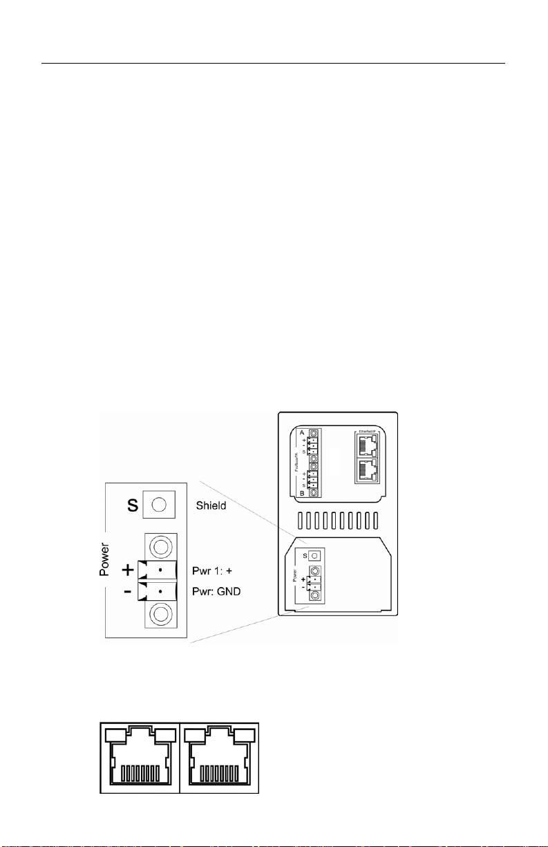
• A 24…32V DC power supply.
• An EtherNet/IP connection via a RJ-45 connector.
Page 3
Redundant EtherNet/IP to PROFIBUS PA Linking Device
3
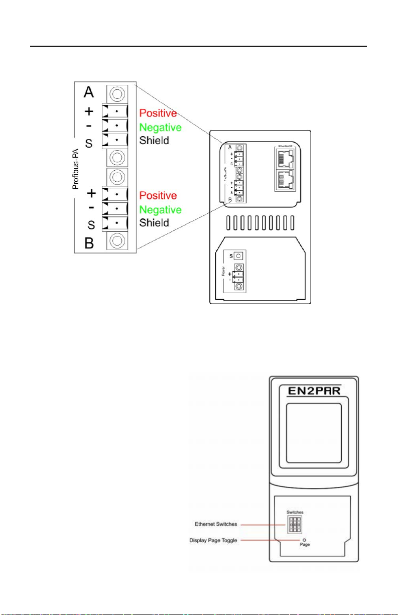
• A PROFIBUS PA network using the IEC61158-2 cable color coding.
Configuration
Complete the following instructions to configure the 1788-EN2PAR linking device.
Configure the Ethernet Address
The module has BOOTP enabled when
shipped. You can set an address via a
BOOTP server or set the hardware
switches to a specific IP address. See Use
BOOTP to Set the IP Address on page
4, or Use Switches to Set the IP Address
on page 4 for details. The switches can be
found under the front cover of the
module.
Page 4

4
Redundant EtherNet/IP to PROFIBUS PA Linking Device
Use BOOTP to Set the IP Address
1. Set the Ethernet switches to 888 (factory default).
2. Apply power to the linking device.
3. Set the IP address by using any BOOTP server.
4. Once the new IP address has been set, power down the linking device.
5. Return the switches to 000.
6. Apply power to the linking device.
Use Switches to Set the IP Address
To set the IP address of the linking device to the 192.168.1.xxx sub net, set the switches to the
required last three digits.
Add a 1788-EN2PAR Module in RSLogix 5000 Software
The module must be added to the RSLogix 5000 IO tree by selecting the 1788-EN2PAR
module (under an Allen-Bradley Ethernet bridge, such as EN2T).
1. Right-click the Ethernet bridge and choose New Module.
2. Expand the Hiprom Technologies option and select 1788-EN2PAR
The Module Properties dialog box appears.
3. Type the module’s Name, Description, IP Address, and RPI.
4. Click OK.
Page 5

Redundant EtherNet/IP to PROFIBUS PA Linking Device
5
5. Open the 1788-EN2PAR linking device’s Module Properties dialog box and click
the Configuration tab.
6. Configure the linking device by setting the required Topology mode and Max Scan
Address.
7. Download the configuration to your controller.
8. Go online with the controller to see all attached field devices, which will appear in
the Configuration tree on the left side below the Master.
Field devices can now be configured.
Operation
The following features can be used to view the data and status of the field devices connected to
the 1788-EN2PAR linking device.
Page 6

6
Redundant EtherNet/IP to PROFIBUS PA Linking Device
RSLogix 5000 Software
The data and status for each field device can be found in FieldDevice tags of the profile as
shown below.
Display
The LCD will display the status of Master as well as each field device. More detail can be seen
by pressing the Page button under the front cover.
Display % of packets received
>>> 95+
>> 80+
> 70+
x 60+
xx 50+
xxx Below 50
??? Unknown
Page 7

Redundant EtherNet/IP to PROFIBUS PA Linking Device
7
Notes:
Page 8

8
Redundant EtherNet/IP to PROFIBUS PA Linking Device
Use the Worldwide Locator at
Contact your distributor. You mu st provide a Customer Support case number (call the phone
Rockwell Automation Support
Rockwell Automation provides tech nical information on the Web to assist you in using its products.
At http://www.rockwellautomation.com/support, you can find technical manuals, technical and application notes, sample code and
links to software service packs, and a MySuppor t feature that you can customize to make the best use of these t ools. You can also
visit our Knowledgebase at http:/ /www.rockwellautomation.com/knowledgebase for FAQs, technical information, support chat and
forums, software updates, and to sign up for product notification updates.
For an additional level of technical phone sup port for installation, configuratio n and troubleshooting, we offer TechConnect
support programs. For more information, contact your local d istributor or Rockwell Automation representative, or visit
http://www.rockwellautomation.com/support/
.
Installation Assistance
If you experience a problem within the first 24 hours of inst allation, please review the information that's contained in this manual.
You can also contact a special Customer Support number for initial help in getting your product up and running.
United States or Canada 1.440.646.3434
Outside United States or
Canada
http://www.rockwellaut omation.com/support/americas/phone_en.html, or contact your local
Rockwell Automation representative.
New Product Satisfaction Return
Rockwell Automation tests all of its prod ucts to ensure that they are fully operational when shipped from the manufacturing facility.
However, if your product is not function ing and needs to be returned, follow these procedures.
SM
United States
Outside United States Please contact your local Rockwell Automation represen tative for the return procedure.
number above to obtain one) to your distributor to complete the return process.
Documentation Feedback
Your comments will help us serve your documentation needs better. If you have any suggestions on how to improve this document,
complete this form, publication RA-DU002
Allen-Bradley, Rockwell Software, Rockwell Au tomation, and TechConnect are trademarks of Rockwell Automation, Inc.
Trademarks not belonging to Rockwell Automation are prope rty of their respective companies.
Rockwell Otomasyon Ticaret A.Ş., Kar Plaza İş Merkezi E Blok Kat: 6 34752 İ çerenköy, İstanbul, Tel: +90 (216) 56 98400
Publication 1788-QS002B-EN-P - -- October 2012
Supersedes Publication 1788-QS002A-EN-P - -- September 2011 Copyright © 2012 Rockwell Automation, Inc. All rights reserved. Printed in the U.S.A.
, available at http://www.rockwellautomation.com/literature/.
 Loading...