

Page 1

User Manual
EtherNet/IP to DeviceNet Linking Device
Catalog Number 1788-EN2DNR
Page 2

Important User Information
IMPORTANT
Read this document and the documents listed in the additional resources section about installation, configuration, and
operation of this equipment before you install, configure, operate, or maintain this product. Users are required to
familiarize themselves with installation and wiring instructions in addition to requirements of all applicable codes, laws,
and standards.
Activities including installation, adjustments, putting into service, use, assembly, disassembly, and maintenance are required
to be carried out by suitably trained personnel in accordance with applicable code of practice.
If this equipment is used in a manner not specified by the manufacturer, the protection provided by the equipment may be
impaired.
In no event will Rockwell Automation, Inc. be responsible or liable for indirect or consequential damages resulting from the
use or application of this equipment.
The examples and diagrams in this manual are included solely for illustrative purposes. Because of the many variables and
requirements associated with any particular installation, Rockwell Automation, Inc. cannot assume responsibility or
liability for actual use based on the examples and diagrams.
No patent liability is assumed by Rockwell Automation, Inc. with respect to use of information, circuits, equipment, or
software described in this manual.
Reproduction of the contents of this manual, in whole or in part, without written permission of Rockwell Automation,
Inc., is prohibited.
Throughout this manual, when necessary, we use notes to make you aware of safety considerations.
WARNING: Identifies information about practices or circumstances that can cause an explosion in a hazardous environment,
which may lead to personal injury or death, property damage, or economic loss.
ATTENTION: Identifies information about practices or circumstances that can lead to personal injury or death, property
damage, or economic loss. Attentions help you identify a hazard, avoid a hazard, and recognize the consequence.
Identifies information that is critical for successful application and understanding of the product.
Labels may also be on or inside the equipment to provide specific precautions.
SHOCK HAZARD: Labels may be on or inside the equipment, for example, a drive or motor, to alert people that dangerous
voltage may be present.
BURN HAZARD: Labels may be on or inside the equipment, for example, a drive or motor, to alert people that surfaces may
reach dangerous temperatures.
ARC FLASH HAZARD: Labels may be on or inside the equipment, for example, a motor control center, to alert people to
potential Arc Flash. Arc Flash will cause severe injury or death. Wear proper Personal Protective Equipment (PPE). Follow ALL
Regulatory requirements for safe work practices and for Personal Protective Equipment (PPE).
Allen-Bradley, Rockwell Software, Studio 5000, Studio 5000 Logix Designer, RSNetWorx, RSLinx , and Rockwell Automation are trademarks of Rockwell Automation, Inc.
Trademarks not belonging to Rockwell Automation are property of their respective companies.
Page 3

Table of Contents
Preface
Linking Device Overview
Install the Linking Device
Additional Resources . . . . . . . . . . . . . . . . . . . . . . . . . . . . . . . . . . . . . . . . . . . . . . . 5
Chapter 1
About the Linking Device . . . . . . . . . . . . . . . . . . . . . . . . . . . . . . . . . . . . . . . . . . 7
Features . . . . . . . . . . . . . . . . . . . . . . . . . . . . . . . . . . . . . . . . . . . . . . . . . . . . . . . . . . . 8
Linking Device Features . . . . . . . . . . . . . . . . . . . . . . . . . . . . . . . . . . . . . . . . 8
EtherNet/IP Features. . . . . . . . . . . . . . . . . . . . . . . . . . . . . . . . . . . . . . . . . . . 8
DeviceNet Features. . . . . . . . . . . . . . . . . . . . . . . . . . . . . . . . . . . . . . . . . . . . . 8
DeviceNet Standard and Safety I/O . . . . . . . . . . . . . . . . . . . . . . . . . . . . . . . . . 8
Add I/O Online (Online Scanlist Changes Allowed in Run Mode). . . . . 8
Chapter 2
System Requirements. . . . . . . . . . . . . . . . . . . . . . . . . . . . . . . . . . . . . . . . . . . . . . . 9
Required Hardware. . . . . . . . . . . . . . . . . . . . . . . . . . . . . . . . . . . . . . . . . . . . . 9
Required Software. . . . . . . . . . . . . . . . . . . . . . . . . . . . . . . . . . . . . . . . . . . . . . 9
Connect the Linking Device to the EtherNet/IP Network. . . . . . . . . . . 10
Connect the Linking Device to the DeviceNet Network. . . . . . . . . . . . . 10
Set the DeviceNet Node Address and Data Rate . . . . . . . . . . . . . . . . . . . . 11
Set the DeviceNet Node Address and Data Rate by Using the
Rotary Switches . . . . . . . . . . . . . . . . . . . . . . . . . . . . . . . . . . . . . . . . . . . . . . 11
Set the DeviceNet Node Address and Data Rate
by Using RSNetWorx for DeviceNet Software. . . . . . . . . . . . . . . . . . 12
Set the Linking Device IP Address . . . . . . . . . . . . . . . . . . . . . . . . . . . . . . . . . 12
Set the Linking Device IP Address by Using the Rotary Switches . 12
Set the Linking Device IP Address by Using DHCP/BOOTP . . . 13
Set the Linking Device IP Address by Using RSLinx Software . . . . 15
Set the Linking Device IP Address by Using the Linking Device
Web Pages . . . . . . . . . . . . . . . . . . . . . . . . . . . . . . . . . . . . . . . . . . . . . . . . . . . 16
Configure the Driver in RSLinx Software . . . . . . . . . . . . . . . . . . . . . . . . . . 18
Register the EDS File . . . . . . . . . . . . . . . . . . . . . . . . . . . . . . . . . . . . . . . . . . . . . 18
Configure the Linking Device
Chapter 3
RSNetWorx for DeviceNet Software . . . . . . . . . . . . . . . . . . . . . . . . . . . . . . 19
Set the DeviceNet Node Address and Data Rate . . . . . . . . . . . . . . . . 20
Enable/Disable Autobaud. . . . . . . . . . . . . . . . . . . . . . . . . . . . . . . . . . . . . 23
Configure DeviceNet I/O . . . . . . . . . . . . . . . . . . . . . . . . . . . . . . . . . . . . 25
Studio 5000 Environment . . . . . . . . . . . . . . . . . . . . . . . . . . . . . . . . . . . . . . . . 28
Add the Linking Device to a Logix Designer Application . . . . . . . . 28
Configure the Linking Device . . . . . . . . . . . . . . . . . . . . . . . . . . . . . . . . . 28
Assembly Objects and Connections . . . . . . . . . . . . . . . . . . . . . . . . . . . . 31
Rockwell Automation Publication 1788-UM059A-EN-P - August 2014 3
Page 4

Table of Contents
Chapter 4
USB Cable
SD Card
Diagnostic Web Pages
Connect via USB to the Linking Device . . . . . . . . . . . . . . . . . . . . . . . . . . . . 33
Configure the USB Driver. . . . . . . . . . . . . . . . . . . . . . . . . . . . . . . . . . . . . 34
Chapter 5
Install or Remove the SD Card . . . . . . . . . . . . . . . . . . . . . . . . . . . . . . . . . . . . 37
Load or Store to the SD Card. . . . . . . . . . . . . . . . . . . . . . . . . . . . . . . . . . . . . . 38
Store to the SD Card. . . . . . . . . . . . . . . . . . . . . . . . . . . . . . . . . . . . . . . . . . 38
Load from the SD Card . . . . . . . . . . . . . . . . . . . . . . . . . . . . . . . . . . . . . . . 39
Chapter 6
Diagnostic Web Pages—DeviceNet . . . . . . . . . . . . . . . . . . . . . . . . . . . . . . . . 41
DeviceNet Status . . . . . . . . . . . . . . . . . . . . . . . . . . . . . . . . . . . . . . . . . . . . . 41
Active Nodes . . . . . . . . . . . . . . . . . . . . . . . . . . . . . . . . . . . . . . . . . . . . . . . . . 41
Idle Nodes . . . . . . . . . . . . . . . . . . . . . . . . . . . . . . . . . . . . . . . . . . . . . . . . . . . 41
Faulted Nodes. . . . . . . . . . . . . . . . . . . . . . . . . . . . . . . . . . . . . . . . . . . . . . . . 41
Invalid Nodes . . . . . . . . . . . . . . . . . . . . . . . . . . . . . . . . . . . . . . . . . . . . . . . . 42
Node Status . . . . . . . . . . . . . . . . . . . . . . . . . . . . . . . . . . . . . . . . . . . . . . . . . . 42
Diagnostic Web Pages—Ethernet. . . . . . . . . . . . . . . . . . . . . . . . . . . . . . . . . . 44
Diagnostic Overview. . . . . . . . . . . . . . . . . . . . . . . . . . . . . . . . . . . . . . . . . . 44
Network Settings . . . . . . . . . . . . . . . . . . . . . . . . . . . . . . . . . . . . . . . . . . . . . 44
Ethernet Statistics . . . . . . . . . . . . . . . . . . . . . . . . . . . . . . . . . . . . . . . . . . . . 44
Ring Statistics . . . . . . . . . . . . . . . . . . . . . . . . . . . . . . . . . . . . . . . . . . . . . . . . 45
Diagnostic Web Pages—Miscellaneous. . . . . . . . . . . . . . . . . . . . . . . . . . . . . 45
Crash Display . . . . . . . . . . . . . . . . . . . . . . . . . . . . . . . . . . . . . . . . . . . . . . . . 45
Heap Statistics . . . . . . . . . . . . . . . . . . . . . . . . . . . . . . . . . . . . . . . . . . . . . . . 45
Appendix A
Status Indicators
Linking Device . . . . . . . . . . . . . . . . . . . . . . . . . . . . . . . . . . . . . . . . . . . . . . . . . . . 47
EtherNet/IP Network . . . . . . . . . . . . . . . . . . . . . . . . . . . . . . . . . . . . . . . . . . . . 47
DeviceNet Network . . . . . . . . . . . . . . . . . . . . . . . . . . . . . . . . . . . . . . . . . . . . . . 47
Index
4 Rockwell Automation Publication 1788-UM059A-EN-P - August 2014
Page 5
Preface
Additional Resources
These documents contain additional information concerning related products
from Rockwell Automation.
Resource Description
Industrial Automation Wiring and Grounding Guidelines,
publication 1770-4.1
DeviceNet Media Design and Installation Guide,
publication DNET-UM072
DeviceNet Network Configuration User Manual,
publication DNET-UM004
DeviceNet Modules Installation Instructions,
publication DNET-IN001
EtherNet/IP Embedded Switch Technology Application
Guide, publication ENET-AP005
Product Certifications website, http://www.ab.com Provides declarations of conformity, certificates, and other
Provides general guidelines for installing a Rockwell
Automation industrial system.
Provides information about how to design, install and
troubleshoot a DeviceNet cable system.
Describes how to use DeviceNet modules with your
Logix5000 controller and communicate with various
devices on the DeviceNet network.
Describes how to install and start DeviceNet module
systems with Logix5000 controllers.
Describes how to install, configure and maintain linear
and device level ring (DLR) networks that use Rockwell
Automation EtherNet/IP devices with embedded switch
technology.
certification details.
You can view or download publications at
http:/www.rockwellautomation.com/literature/
. To order paper copies of
technical documentation, contact your local Allen-Bradley distributor or
Rockwell Automation sales representative.
Rockwell Automation Publication 1788-UM059A-EN-P - August 2014 5
Page 6

Preface
Notes:
6 Rockwell Automation Publication 1788-UM059A-EN-P - August 2014
Page 7

Linking Device Overview
Chapter 1
About the Linking Device
The 1788-EN2DNR EtherNet/IP-to-DeviceNet linking device lets you
seamlessly connect your information or control-level networks with your
device-level network.
The linking device provides full DeviceNet master functionality, so you can
connect up to 63 DeviceNet slave devices to an Ethernet TCP/IP interface that
supports the EtherNet/IP network and an HTTP web server. For example, you
could use the linking device to do the following:
• As a gateway to connect information or control-level networks to devicelevel networks for programming, configuration, control, or data collection
• As a router/bridge to connect the EtherNet/IP network to the DeviceNet
network
The linking device provides centralized data storage, or I/O tables, for data
shared between the DeviceNet and EtherNet/IP networks. Data is placed into
the I/O tables by one network interface, allowing the data to be read through the
other network interface.
The linking device appears as a single device on either network by using standard
protocol mechanisms. No special, or extended, protocol features are required for
the devices on either network to read or write the data flowing through the I/O
tables; all cross-network activity is transparent to the devices on either network.
The linking device also supports Device Level Ring (DLR) and CIP Safety
connections.
Phoenix connectors are provided for power and DeviceNet connections. Two
RJ45 style connectors are provided for EtherNet/IP connection.
The linking device can be mounted to a DIN rail.
Rockwell Automation Publication 1788-UM059A-EN-P - August 2014 7
Page 8

Chapter 1 Linking Device Overview
Features
The 1788-EN2DNR module has the following features.
Linking Device Features
For Class 0 CIP Safety connections, 5 ms maximum delay from network to
network
EtherNet/IP Features
• The linking device supports these connections:
– 32 Class 0 connections (Safety)
– 21 Class 1 connections (1 excl. owner, 20 input only/listen only)
– 16 Class 3 connections
• Integrated web server
• Beacon-based DLR (Device Level Ring) support
DeviceNet Features
• 63 nodes on the DeviceNet network
• Master/scanner as well as slave/adapter functionality
• Safety I/O
• Scanner configuration using RSNetWorx™
• Autoscan
• ADR (Automatic Device Replacement) with a capacity of 256 kB
• Quick connect (as originator)
• I/O slave messaging (bit strobe, polling, cyclic, change of state)
for DeviceNet software
DeviceNet Standard and Safety I/O
Add I/O Online (Online Scanlist Changes Allowed in Run Mode)
8 Rockwell Automation Publication 1788-UM059A-EN-P - August 2014
The 1788-EN2DNR linking device features the possibility to bridge CIP safety
messages. It supports 32 CIP safety connections, with a maximum internal delay
of 5 ms.
The Online Scanlist Changes Allowed in Run (OSCAR) feature lets you
manipulate the DeviceNet scanner configuration while the scanner is in Run
mode. Configuration items that can be changed in Run mode include the
scanlist, ADR, and ISD (InterScan Delay). Safety I/O cannot be added to the
scanlist.
Page 9

Install the Linking Device
Chapter 2
System Requirements
The following hardware and software components are required to use the linking
device.
Required Hardware
• 1788-EN2DNR linking device
• Two 121 Ω (1%, 1/4 watt) termination resistors (shipped with the linking
device)
• DeviceNet cabling, power, and devices forming a DeviceNet network
• Ethernet cabling
• Computer with USB connection or access to the Ethernet network
• 24 V DC power to the linking device
DeviceNet power can be used; however, using DeviceNet power bypasses
the DeviceNet network isolation.
Required Software
• RSNetWorx for DeviceNet software, version 21 or later, to configure
DeviceNet devices and the linking device’s DeviceNet functionality
• RSLinx® software, version 3.51 or later
• RSLogix 5000 version 20 or Studio 5000 Automation Engineering &
Design Environment™, version 21 or later.
Rockwell Automation Publication 1788-UM059A-EN-P - August 2014 9
Page 10
Chapter 2 Install the Linking Device
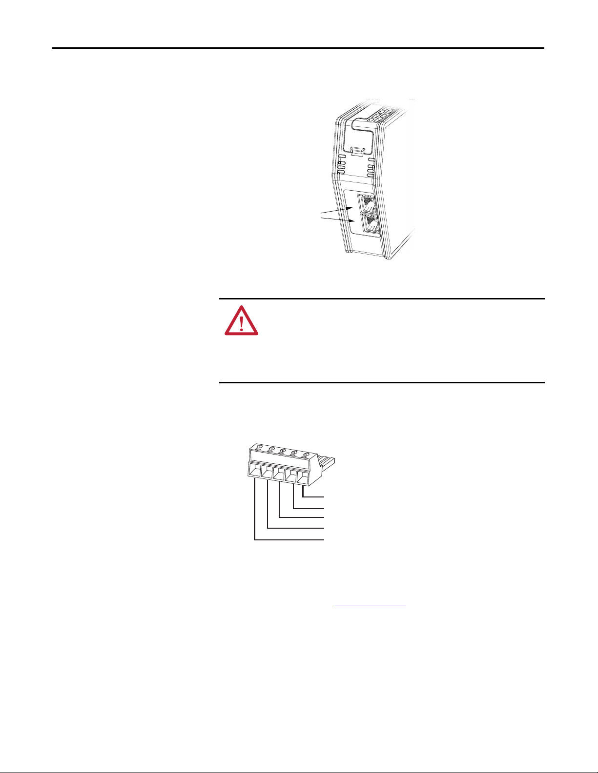
RJ45 Ports
TIP
31442-M
Connect the Linking Device to the EtherNet/IP Network
Connect the Linking Device to the DeviceNet Network
Connect the EtherNet/IP network cable to either of the two RJ45 ports on the
front of the linking device.
ATT EN TI ON : Do not wire more than two conductors on any single terminal. To
comply with the CE Low Voltage Directive (LVD), this equipment must be
powered from a source compliant with safety extra low voltage (SELV) or
protected extra low voltage (PELV). To comply with UL restrictions, this
equipment must be powered from a source compliant with Class 2 or Limited
Vol tage /Curren t.
1. With power to the linking device off, connect the DeviceNet network
cable to the DeviceNet connector on the linking device.
The female terminal block connector is provided with the linking device.
(Red) Net Power 24V DC
(White) CAN High +
CAN Shield
(Blue) CAN Low
(Black) Net Power 24V DC Common
The two 121 ? termination resistors that come with the linking device are
required for proper network termination at each end of the trunk line. See the
DeviceNet Specification (available from the Open DeviceNet Vendors
Association at http://www.odva.org
) for specific rules on DeviceNet
connections and termination.
10 Rockwell Automation Publication 1788-UM059A-EN-P - August 2014
Page 11
Install the Linking Device Chapter 2
123
NA x10
NA x1
DATA RATE
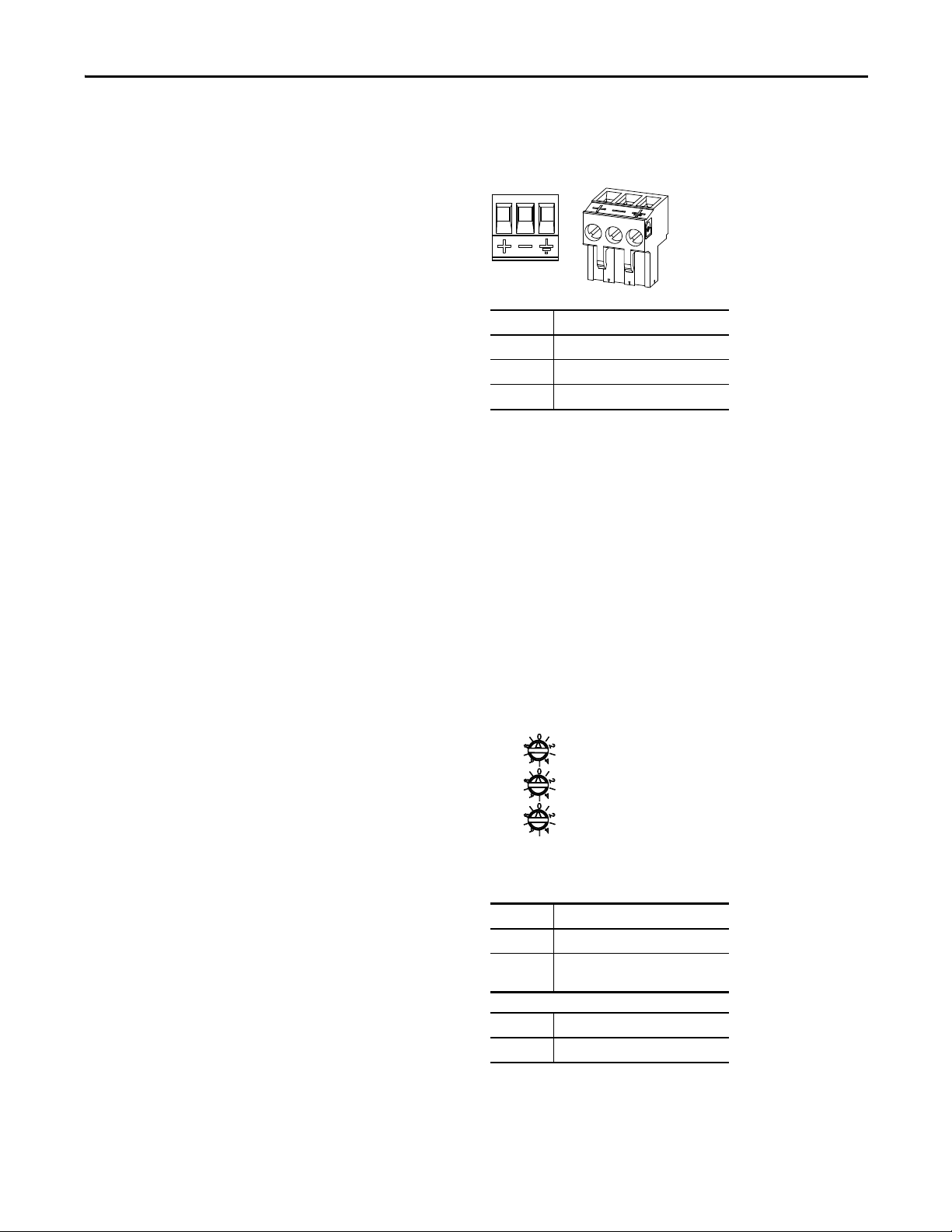
2. Connect the power cable to the linking device.
The female terminal block connector is provided with the linking device.
Pin No. Description
1 +24 V DC
2GND
3PE (Protective Earth)
3. Apply power to the linking device and DeviceNet network.
Set the DeviceNet Node Address and Data Rate
Two methods can be used to set the DeviceNet node address and the data rate:
• Use the node address and data rate rotary switches on the side of the
linking device
• Use RSNetWorx for DeviceNet software
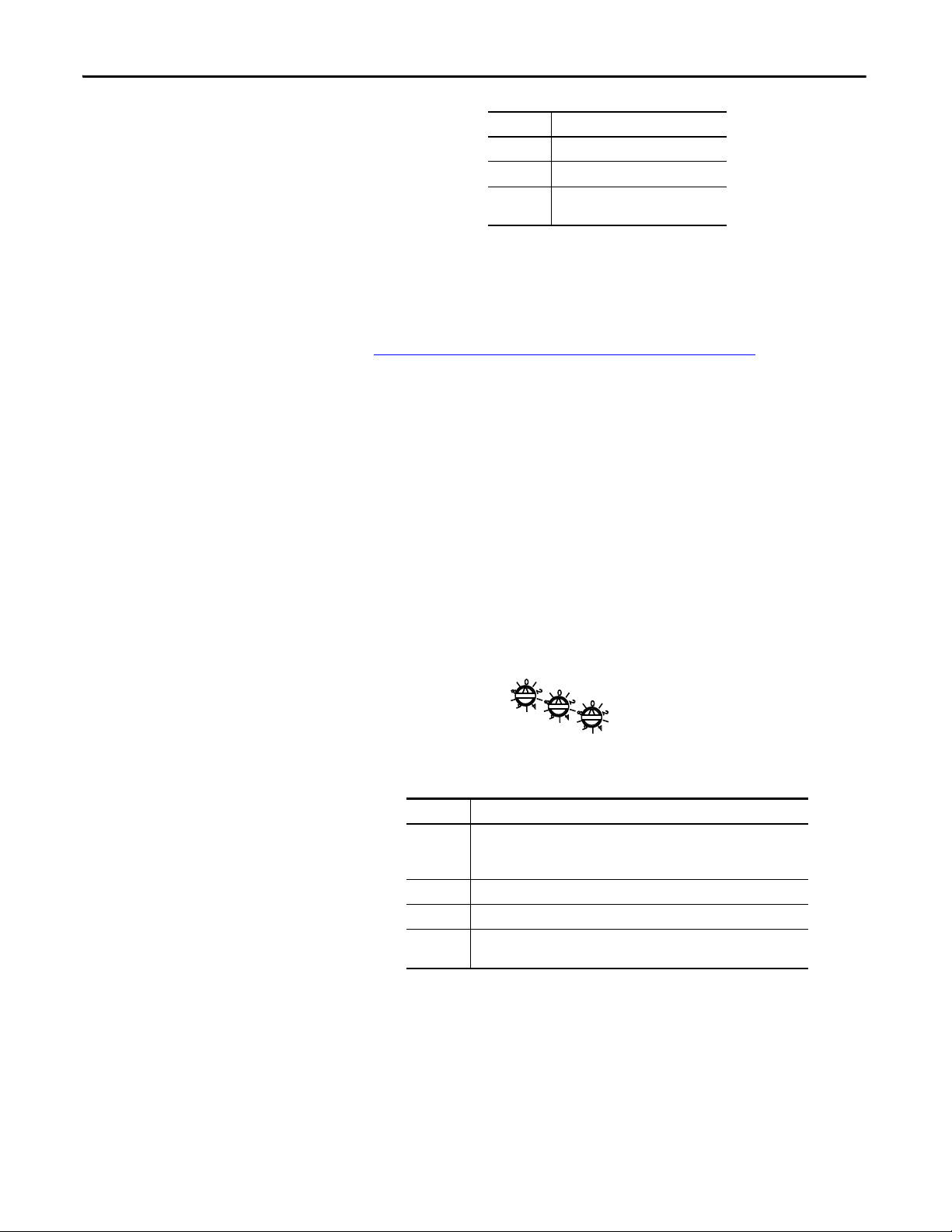
Set the DeviceNet Node Address and Data Rate by Using the Rotary Switches
The rotary switches are on the right side of the linking device.
Set the desired node address and data rate according to the table below.
Switch Node Address
00 - 63 DeviceNet node address
Other value Node address selected via RSNetWorx
software
Switch Data Rate
0 125 kbps
Rockwell Automation Publication 1788-UM059A-EN-P - August 2014 11
Page 12
Chapter 2 Install the Linking Device
x100
x10
x1
Switch Data Rate
1 250 kbps
2 500 kbps
Other value Data rate selected via RSNetWorx
software
Set the DeviceNet Node Address and Data Rate by Using RSNetWorx for DeviceNet Software
See Set the DeviceNet Node Address and Data Rate on page 20 for information
about using RSNetWorx software to set node address and data rate.
Set the Linking Device IP Address
Four methods can be used to set the linking device IP address:
• Use the IP address rotary switches on the side of the linking device
• Use the DHCP protocol
• Use RSLinx Software
• Use the web pages of the linking device
Set the Linking Device IP Address by Using the Rotary Switches
The rotary switches are on the right side of the linking device.
Set the IP address according to the table below.
Switch IP Address
000 Administrative mode
The linking device uses the IP address that was used last startup
The web pages are available
001 - 254 192.168.1.XYZ where XYZ is the value of the three switches
888 Reset the linking device to initial out-of-box settings
Other value The linking device starts in operating mode, using the latest configured IP
address
12 Rockwell Automation Publication 1788-UM059A-EN-P - August 2014
Page 13
Install the Linking Device Chapter 2
TIP
Set the Linking Device IP Address by Using DHCP/BOOTP
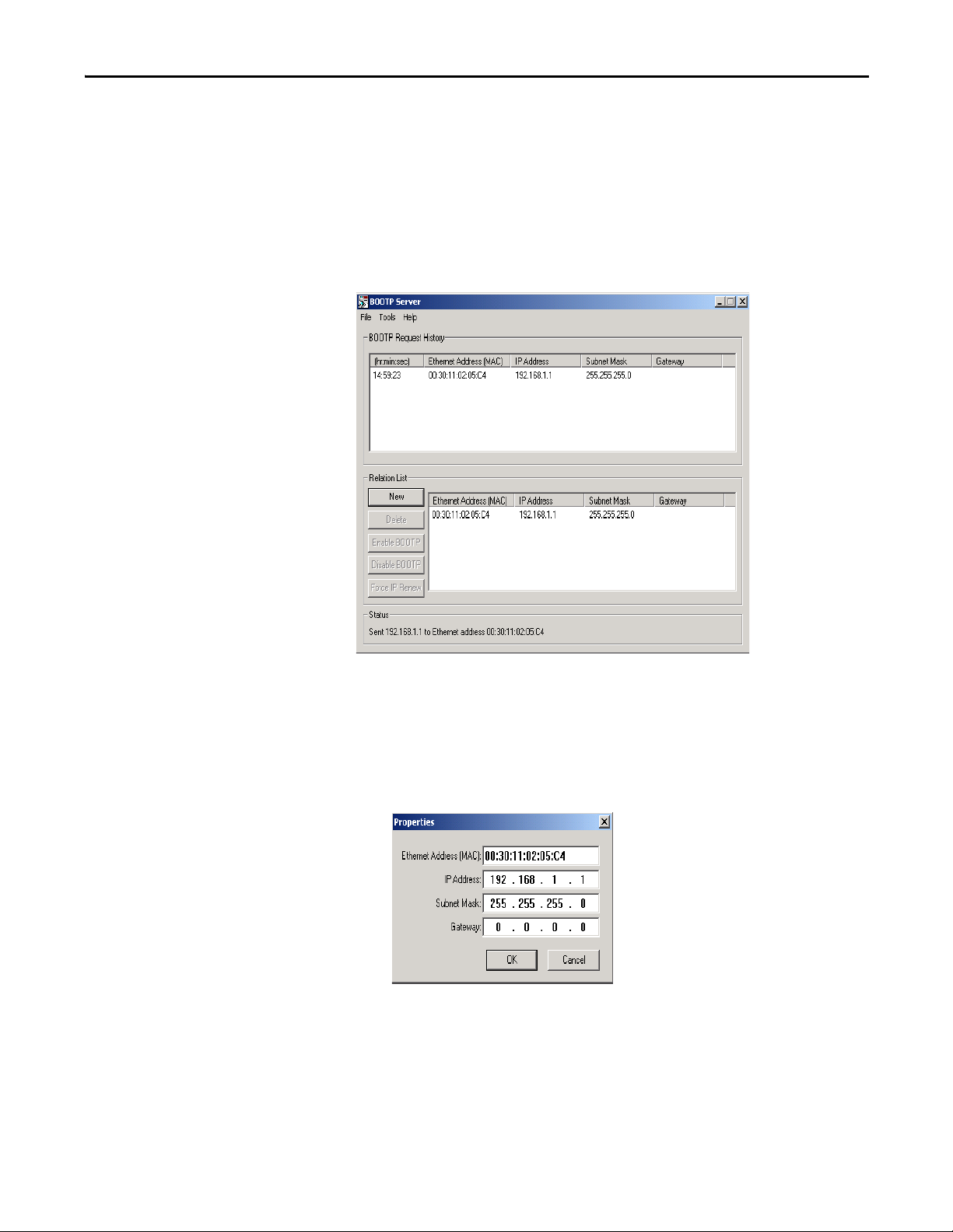
The use of DHCP is the default configuration for the linking device as shipped.
When DHCP/BOOTP is enabled and a DHCP or BOOTP server is found, the
IP address, subnet mask, and gateway address are automatically configured by the
DHCP server, as shown in the following figure.
Automatic Configuration
Launch a DHCP/BOOTP Server. If using the Rockwell Automation DHCP/
BOOTP server, then follow these steps to change the IP address, Subnet mask,
and Gateway address from this dialog box.
1. Click New.
The Properties dialog box appears.
2. Enter the appropriate values into the following boxes.
• Ethernet address (MAC ID) from the linking device product ID label
• IP address
• Subnet Mask
• Gateway (IP address)
3. Click OK.
Rockwell Automation Publication 1788-UM059A-EN-P - August 2014 13
Page 14
Chapter 2 Install the Linking Device
TIP
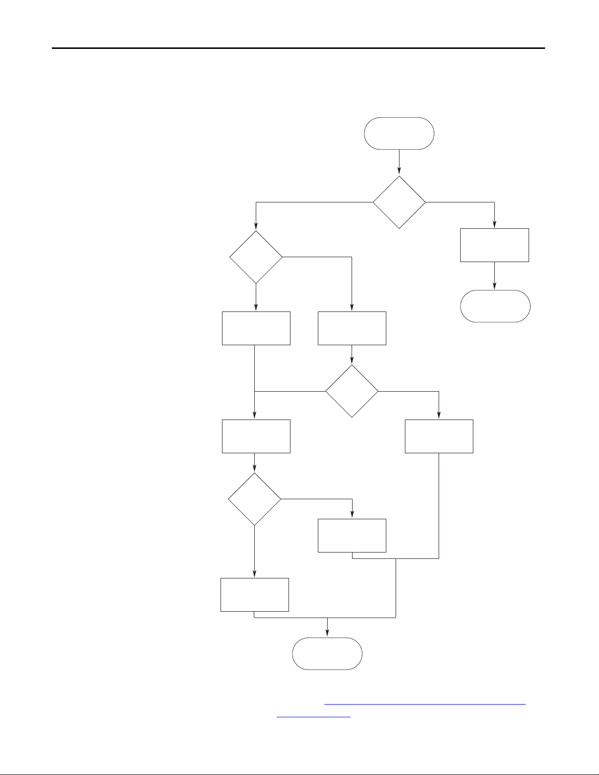
The following figure shows a flowchart describing how the IP configuration is
determined when the linking device is powered up.
IP Configuration Flowchart
Start
No
Rotary
Switches = 000?
Yes
Admin Mode Operational Mode
No Yes
Fetch Stored Settings
No
Rotary
Switches
1 - 254?
Rotary
Switches = 888?
IP Address:
192.168.1.X
Yes
Factory Reset to DHCP
LED Indication
DHCP
Enabled?
No
IP Address:
Static Setting
Yes
Start up
You can enable these values by using the linking device’s IP Configuration web
page. Refer to Set the Linking Device IP Address by Using the Linking Device
Web Pages on page 16.
14 Rockwell Automation Publication 1788-UM059A-EN-P - August 2014
Fetch IP Address
from Server
Page 15
Install the Linking Device Chapter 2
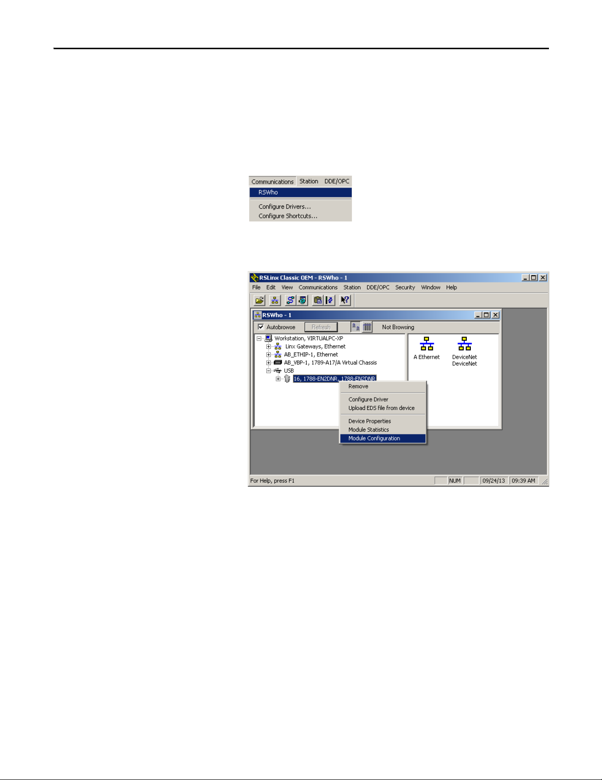
Set the Linking Device IP Address by Using RSLinx Software
To use RSLinx software to set the IP address of the linking device, follow these
steps.
1. Connect to the linking device using a USB cable.
2. From the Communications menu, choose RSWho.
3. Navigate to the USB port.
4. Right-click the linking device and choose Module Configuration.
5. Click the Port Configuration tab.
6. For Network Configuration Type, click Static to permanently assign this
configuration to the port.
7. Type the desired information in the appropriate boxes.
Rockwell Automation Publication 1788-UM059A-EN-P - August 2014 15
Page 16
Chapter 2 Install the Linking Device
IMPORTANT
8. Configure the port settings.
To Th en
Use the default port speed and duplex
settings
Manually configure your port’s speed
and duplex settings
Consider the following when you configure the linking device’s port
settings:
• If the linking device is connected to an unmanaged switch, leave
Auto-negotiate port speed and duplex checked or the
communications to the linking device fails.
• If you are forcing the port speed and duplex with a managed
switch, the corresponding port of the managed switch must be
forced to the same settings or the linking device fails.
Leave Auto-negotiate port speed and duplex checked.
This setting determines the actual speed and duplex setting.
Follow these steps.
1. Clear the Auto-negotiate port speed and duplex checkbox.
2. From the Current Port Speed pull-down menu, choose a port
speed.
3. From the Current Duplex pull-down menu, choose the
appropriate Duplex value.
9. Click OK.
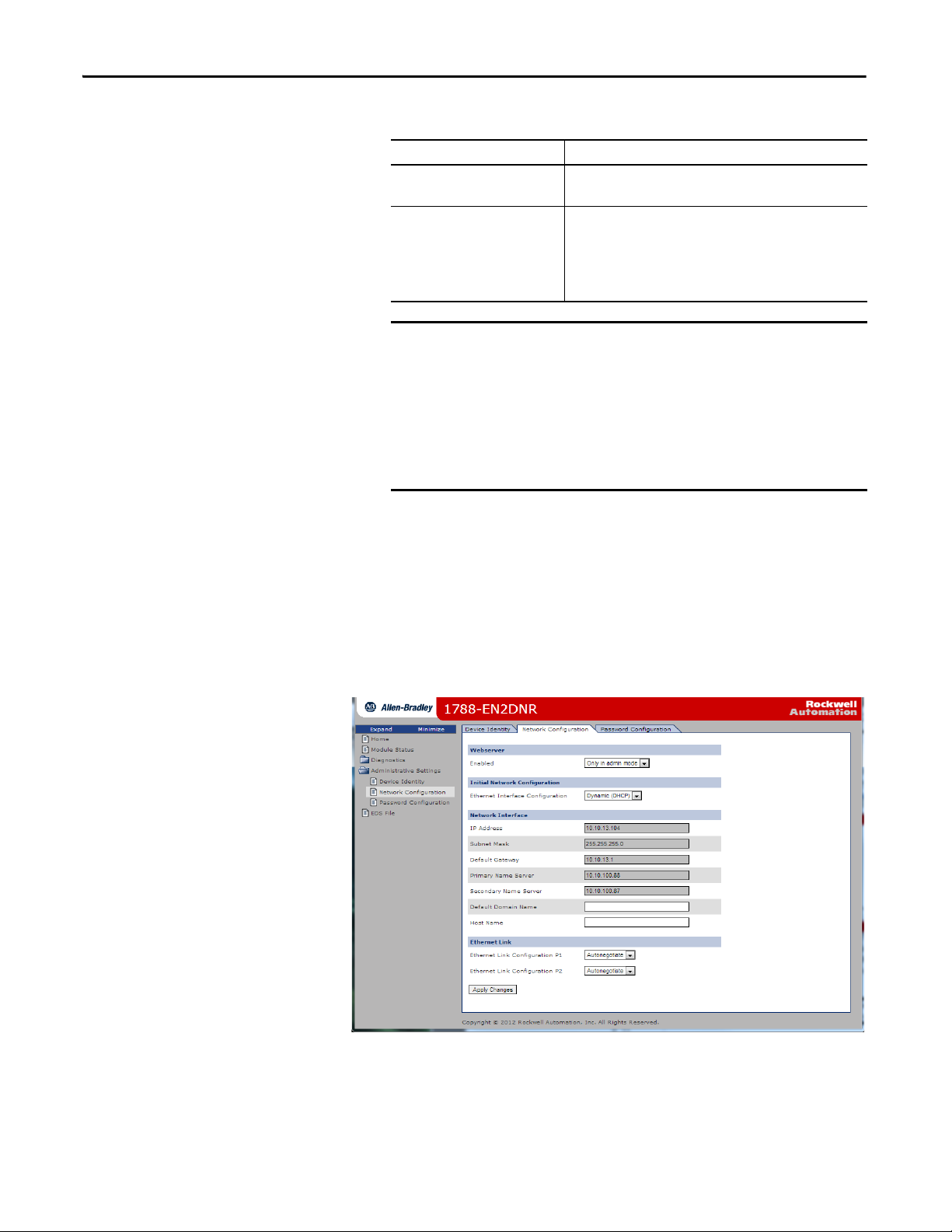
Set the Linking Device IP Address by Using the Linking Device Web Pages
The EtherNet/IP address can also be configured by using the Network
Configuration web page on the linking device, as shown in the following figure.
16 Rockwell Automation Publication 1788-UM059A-EN-P - August 2014
Page 17

Install the Linking Device Chapter 2
IMPORTANT
The IP address can be set with the web page only if the linking device already has
a valid IP address. One way that you can do this is by using the rotary switch to
force the linking device to use the IP address from the switches after you cycle
power. Follow these steps to configure the IP address with the web page.
Because the rotary switches setting overrides other IP address configurations,
be sure to set the rotary switches to the 0 position before continuing.
1. Browse to the linking device by entering the IP address set by the switches
in your web browser’s address bar and press Enter.
2. In the left pane, click Network Configuration.
The Enter Network Password dialog box appears.
3. In the User Name box, type Administrator.
4. In the password box, type the default password, which is the serial number
of the linking device in hexadecimal format, upper case.
The serial number can be found on the 1788-EN2DNR web page.
5. Click OK.
The Network Configuration dialog box appears.
Rockwell Automation Publication 1788-UM059A-EN-P - August 2014 17
Page 18

Chapter 2 Install the Linking Device
6. In the Network Configuration dialog box, enter the following values.
Description Type
IP Address Any valid value. See your system administrator for a
valid IP address.
Subnet Mask Any valid value.
Default Gateway
Primar y Name Server
Secondary Name Server
Default Domain Name
Host Name
7. Click Apply Changes.
8. Follow the on-dialog box prompts.
9. Cycle power to the linking device.
Configure the Driver in RSLinx Software
Register the EDS File
1. In RSLinx software, choose Communications > Configure Drivers.
2. From the Available Driver Types pull-down menu, choose EtherNet/IP
Driver.
3. Click Add New.
4. In the Add New RSLinx Drivers dialog box, click OK.
5. In the Configure Driver window, select the EtherNet/IP network
interface, and click OK.
6. Click Close.
The EDS file for the linking device is accessible and downloadable with RSLinx.
To register the EDS file in RSLinx software, follow these steps.
1. In RSLinx software, right-click the linking device.
2. Select Upload EDS File from Device.
3. Click Next or Finish for the remaining dialog boxes.
18 Rockwell Automation Publication 1788-UM059A-EN-P - August 2014
Page 19

Configure the Linking Device
Chapter 3
RSNetWorx for DeviceNet Software
1. In RSNetWorx for DeviceNet software, choose Network > Online.
2. In the left pane, click the RSLinx Ethernet driver you added previously.
See Configure the Driver in RSLinx Software on page 18
3. In the left pane, click the + next to the 1788-EN2DNR linking device
icon.
4. In the left pane, choose DeviceNet, DeviceNet.
.
5. When asked to upload from the network, click OK to perform a single
pass browse.
Rockwell Automation Publication 1788-UM059A-EN-P - August 2014 19
Page 20

Chapter 3 Configure the Linking Device
Set the DeviceNet Node Address and Data Rate
Note that, to be able to set the node address and the data rate from RSNetWorx
software, the rotary switches must be set to any value other than 0 - 63.
1. In RSNetWorx for DeviceNet software, choose Tools > Node
Commissioning.
The Node Commissioning dialog box appears.
2. On the Node Commissioning dialog box, click Browse.
The Device Selection dialog box appears.
3. In the left pane, click the + next to the RSLinx driver for the
1788-EN2DNR linking device.
20 Rockwell Automation Publication 1788-UM059A-EN-P - August 2014
Page 21

Configure the Linking Device Chapter 3
4. In the left pane of the dialog box, click the + next to the IP address for the
1788-EN2DNR linking device.
5. In the left pane, click the + next to the DeviceNet network.
You see the 1788-EN2DNR linking device in the left pane.
6. Click the 1788-EN2DNR linking device in the left pane.
The linking device appears in the right pane.
7. Click OK.
8. If a warning text box asking you if you wish to continue appears, click Yes.
9. Enter the desired node address or data rate, then click Apply.
Rockwell Automation Publication 1788-UM059A-EN-P - August 2014 21
Page 22

Chapter 3 Configure the Linking Device
IMPORTANT
TIP
10. Click Close.
The linking device automatically restarts the DeviceNet network if a
new node address is entered. If the communication rate is changed,
you must cycle power to the linking device before the new
communication rate takes effect.
Note: Data rate changes can cause bus-off errors. Do not change the
data rate during live network performance.
11. Restart RSNetWorx for DeviceNet software and go online.
If you are using the linking device as a network gateway, you need to
restart RSNetWorx for DeviceNet software before continuing.
22 Rockwell Automation Publication 1788-UM059A-EN-P - August 2014
Page 23

Configure the Linking Device Chapter 3
IMPORTANT
Enable/Disable Autobaud
Autobaud is disabled by default. You can turn it on or off by following the
procedure below.
1. In RSNetWorx for DeviceNet software, click the linking device icon.
2. From the Device pull-down menu, choose Class Instance.
3. If a warning dialog box appears, click Yes.
The Class Instance Editor dialog box appears.
4. From the Description pull-down menu, choose Set Single Attribute.
5. Choose the appropriate options in the Class Instance Editor dialog box.
In This Box Choose
Object Address
Class
Instance
Attribute
Data Sent to Device 00 to enable Autobaud
Tra nsm it D ata Size By te
3
1
64h
01 to disable Autobaud
Make sure the Values in Decimal checkbox is cleared.
Rockwell Automation Publication 1788-UM059A-EN-P - August 2014 23
Page 24

Chapter 3 Configure the Linking Device
IMPORTANT
6. Click Execute.
A message in the ‘Data received from device’ box indicates that the
execution was completed.
7. Click Close.
Changes to the autobaud option configuration do not take effect until
you cycle power to the linking device. You may also have to cycle power
to the slave devices.
If the linking device is the only master on the DeviceNet network, do
not enable autobaud. Automatic detection requires traffic on the
network. There is typically no traffic until a master attempts to
establish a connection.
Enable autobaud only if there are three or more devices on the
network, including the linking device.
24 Rockwell Automation Publication 1788-UM059A-EN-P - August 2014
Page 25

Configure the Linking Device Chapter 3
IMPORTANT
IMPORTANT
TIP
IMPORTANT
Configure DeviceNet I/O
Steps 8 and 9 are required only if the linking device is used as an I/O scanner.
The linking device can function as a gateway/bridge for explicit messaging and
safety I/O routing, even if no I/O is configured.
I/O Mapping
The DeviceNet I/O configuration defines the format of the Input and Output
tables, or the mapping of DeviceNet slaves’ I/O data to the I/O tables. As slaves
are added to the linking device’s DeviceNet scanner configuration, the location in
the I/O tables of each part of the slave’s I/O data is determined and stored.
The organization of the I/O tables is very important. I/O tables define the
format of the data that is provided to the EtherNet/IP scanner. Plan and
document the Input and Output table formats to be sure the EtherNet/IP
scanner is working with the correct data from the DeviceNet network.
The size of the I/O data that can be exchanged with the EtherNet/IP scanner
(and, hence, the size of the I/O tables) is restricted as explained below:
• The Input table size cannot be larger than 496 bytes.
• The Output table size cannot be larger than 492 bytes.
• Either table can be empty (0 bytes).
To configure standard DeviceNet I/O, use RSNetWorx for DeviceNet software
to set the linking device’s scan list and I/O table mapping.
To configure CIP Safety I/O, see the following:
• GuardLogix User manual: 1756-UM020H-EN-P - April 2012
• 1791DS User manual: 1791DS-UM001J-EN-P - May 2013
Automap is used in this example for simplicity. In some cases, if you want to
organize the I/O data in other ways, use the Advanced data table editor in the
Input and Output tabs. Refer to RSNetWorx online help for complete details.
1. In RSNetWorx for DeviceNet software, from the Network menu, choose
Online.
2. From the Network menu, choose Single Pass Browse.
Wait for browsing to complete.
3. From the Network menu, choose Upload from Network.
Wait for the device information to be uploaded from the network.
Rockwell Automation Publication 1788-UM059A-EN-P - August 2014 25
Page 26

Chapter 3 Configure the Linking Device
4. Double-click the linking device icon to open the Module Description
dialog box.
Several tabs appear on the top of the dialog box.
5. Click the Scanlist tab.
6. In the informational dialog box that appears, click Upload.
The dialog box shows two columns. On the left is a list of available devices
that can be added to the scan list. On the right is a list of devices that are
configured in the scan list.
7. Check AutoMap on Add.
8. Select the I/O devices on the left side of the dialog box and click > to move
it to the right side of the dialog box.
9. Click the Input tab.
26 Rockwell Automation Publication 1788-UM059A-EN-P - August 2014
Page 27

The Input mapping dialog box appears.
TIP
The top portion of this dialog box lists the
devices in the scan list from which the linking
device receives input data. The bottom shows
the location in the Input table where the data
is placed for each device. This shows the
format of the Input table of the linking
device. This is the format of the input data
that is sent to the EtherNet/IP scanner.
The top portion of this dialog box lists the
devices in the scan list from which the linking
device sends output data. The bottom shows
the location in the Output table where the
data is placed for each device. This shows the
format of the Output table of the linking
device. This is the format of the output data
that is sent to the linking device from the
EtherNet/IP scanner.
10. Click the Output tab.
The Output mapping dialog box appears.
Configure the Linking Device Chapter 3
11. Click Apply, and click Yes to download the scan list to the linking device.
The linking device starts scanning as soon as it finds entries in its scan list.
However, in Idle mode, output data is not sent to the devices.
12. Click OK.
Rockwell Automation Publication 1788-UM059A-EN-P - August 2014 27
Page 28

Chapter 3 Configure the Linking Device
Studio 5000 Environment
These procedures explain how to work with the linking device in the
Studio 5000® environment.
Add the Linking Device to a Logix Designer Application
1. In the Studio 5000 Logix Designer™ application, from the File menu,
choose New to create a new project.
The New Controller dialog box appears.
2. From the Type pull-down menu, choose the controller type.
3. From the Revision pull-down menu, choose the controller version.
4. In the Name box, type a name for the controller project.
5. Click OK.
A project is created.
Configure the Linking Device
1. In the left pane, right-click I/O Configuration.
2. Click New Module.
3. From the Select Module Type dialog box, select any EtherNet/IP bridge
module (such as the 1756-EN2TR module) and click Create.
The New Module dialog box appears.
4. In the Slot Number pull-down, choose the slot number in which the device
resides.
5. Click OK.
6. In the right pane, right-click the EtherNet/IP module you just added to
your project and choose New Module.
28 Rockwell Automation Publication 1788-UM059A-EN-P - August 2014
Page 29

Configure the Linking Device Chapter 3
7. From the Select Module Type dialog box, select 1788-EN2DNR 1788
Ethernet to DeviceNet Linking Device and click Create.
The AOP needs to be installed for the linking device to show up in the list.
The AOP is available here: https://download.rockwellautomation.com/
esd/download.aspx?downloadid=addonprofiles
The New Module dialog box appears.
8. In the Name box, enter a module name.
9. Click IP Address and type the IP address for which the linking device is
configured.
10. Click the Connection tab.
11. Enter the Requested Packet Interval (RPI or update rate) in a range from
2…750 ms.
12. Click the RSNetWorx tab.
Rockwell Automation Publication 1788-UM059A-EN-P - August 2014 29
Page 30

Chapter 3 Configure the Linking Device
TIP
13. If an RSNetWorx for DeviceNet configuration file (filename *.dnt) already
exists for the linking device, enter or browse to the appropriate filename.
Doing so lets RSNetWorx for DeviceNet software launch directly from the
Studio 5000 environment.
14. Click OK.
You can now use the linking device as both a bridge and a scanner.
15. Write a user program to use the linking device on the network.
Consult Rockwell Automation Technical Support or your Rockwell
Automation representative for assistance in writing the program.
16. To view information specific to the Logix Designer application tags that
pertain to the linking device, do the following.
a. In the left pane, click Controller Tags.
In the right pane, you see the 1788-EN2DNR linking device controller
tags.
b. Click the + to the left of the tag name to expand it.
c. Review data in the boxes that appear for each tag, as described in the
section entitled Assembly Objects and Connections on page 31
30 Rockwell Automation Publication 1788-UM059A-EN-P - August 2014
.
Page 31

Configure the Linking Device Chapter 3
IMPORTANT
Assembly Objects and Connections
Three Assembly Object instances are accessible from the EtherNet/IP network:
input, output and status. The input and output assemblies are linked to the input
and output tags created in the Studio 5000 environment. The status assembly
provides current status information about the linking device.
With a specific 1788-EN2DNR profile, I/O tags are mapped without an offset.
For example, the Logix Designer application input tag EN2DNR:I:Data[0]
corresponds to word 0 of the RSNetWorx for DeviceNet software input mapping
table.
The assembly instances associated with these three assemblies are listed in the
following tables.
Input Assembly
The input assembly contains a 32-bit status register followed by the data in the
linking device’s input data table.
Input Assembly Format
DINT
Offset
0 1 Status register EN2DNR:I.Status Register
1 Up to 123 Input data EN2DNR:I.Data[0 …123]
Size in DINTs Description Studio 5000 Environment Version 21or Later
Example Tags
The input data format and content is determined by the DeviceNet scanner
configuration. The data appears in the table as it is mapped from the DeviceNet
input connections. The input data in the assembly is 124 DINTs long ; however,
only the size of the input data table is used. The remaining space is filled with the
value 0 (zero).
Output Assembly
The output assembly contains a 32-bit command register followed by the data in
the linking device’s output data table.
Output Assembly Format
DINT
Offset
0 1 Command register EN2DNR:O.CommandRegister
1 Up to 124 Output data EN2DNR:O.Data[0 …122]
Size in DINTs Description Studio 5000 Environment Version 21or Later
Example Tags
The output data format and content is determined by the DeviceNet scanner
configuration. The data appears in the table as it is mapped to the DeviceNet
output connections. The output data in the assembly is 123 DINT long;
however, only the size of the output data table is used. The remaining space is
ignored.
Rockwell Automation Publication 1788-UM059A-EN-P - August 2014 31
Page 32

Chapter 3 Configure the Linking Device
IMPORTANT
Status Assembly
The status assembly is a collection of status and diagnostic information for the
linking device’s DeviceNet network interface. The information in the assembly is
updated once a second.
All information in the status assembly is stored in little endian format. The
least significant byte of multibyte values is stored first.
Status Assembly Format
Byte
Offset
0 4 UDINT ScanCounter The number of DeviceNet I/O scans that
4 8 SINT[8] DeviceFailureRegister Indicates which DeviceNet slaves are
12 8 SINT[8] AutoVerifyFailure
20 8 SINT[8] DeviceIdleRegister Indicates which DeviceNet slaves are in
28 8 SINT[8] ActiveNodeRegister Indicates which DeviceNet nodes are
36 4 SINT[4] StatusDisplay Mimics a 4-character alpha-numeric
40 1 USINT ScannerAddress The DeviceNet MAC ID of the linking
41 1 USINT ScannerStatus The current status of the DeviceNet
42 1 USINT ScrollingDevice
43 1 USINT
64 64 USINT[64] DeviceStatus The current status of each DeviceNet slave
Size in
Bytes
Data Type Name (Studio 5000
environment version
21or later)
Register
AddressAndStatus
Description
have taken place since power was applied
to the linking device.
faulted. Each bit represents the status of
the slave at the corresponding MAC ID.
Indicates which DeviceNet slaves are the
incorrect device type. Each bit represents
the status of the s lave at the
corresponding MAC ID.
Idle mode. Each bit represents the status
of the slave at the corresponding MAC ID.
configured in the 1788-EN2DN’s scan list.
Each bit represents the status of the slave
at the corresponding MAC ID.
display. If there are no faults, the display
shows the linking device’s MAC ID and its
Run/Idle status.
If there are faults, the display scrolls
through the MAC IDs of the faulted nodes
and display the error code associated with
each.
device.
scanner.
The scrolling address and status fields
scroll through the address and status of all
DeviceNe t slaves that are faulted. This
scrolling includes the linking device
scanner itself.
If there are no faulted nodes, both the
scrolling address and status are set to 0.
The scrolling fields change once a second.
node. Each array element is the status of
the node at the corresponding MAC ID.
If a node is not configured in the linking
device scan list, the status value is set to 0.
The linking device scanner status appears
at the entry associated with the linking
device MAC ID.
32 Rockwell Automation Publication 1788-UM059A-EN-P - August 2014
Page 33

USB Cable
Chapter 4
Connect via USB to the Linking Device
To use the USB port of the linking device, you must have RSLinx software,
version 2.56 or later, installed on your workstation. Use a USB cable to connect
your workstation to the USB port of the linking device.
With this connection, you can configure the linking device and the DeviceNet
network or upgrade the linking device’s firmware, directly from your workstation.
ATT EN TI ON : The USB port is intended only for temporary connections. The USB
cable is not to exceed 3.0 m (9.84 ft) and must not contain hubs.
WARNING: Do not use the USB port in hazardous locations.
The USB port is on the front of the linking device.
Rockwell Automation Publication 1788-UM059A-EN-P - August 2014 33
Page 34

Chapter 4 USB Cable
TIP
Configure the USB Driver
To configure RSLinx software to use a USB port, you need to configure a USB
driver.
To configure a USB driver, perform this procedure.
1. Connect the linking device and your workstation by using a USB cable.
The Found New Hardware Wizard appears.
2. Click any of the Windows Update connections options and click Next.
If the software for the USB driver is not found and the installation is
cancelled, verify that you have installed RSLinx Classic software,
version 2.57 or later.
3. Click Install the software automatically (Recommended) and click Next.
The software is installed.
34 Rockwell Automation Publication 1788-UM059A-EN-P - August 2014
Page 35

USB Cable Chapter 4
4. Click Finish to set up your USB driver.
To browse to the linking device in RSLinx software, click the RSWho
icon.
The RSLinx Workstation organizer appears.
The linking device appears under two different drivers, a virtual chassis
and the USB port. You can use either driver to browse to the linking
device.
Rockwell Automation Publication 1788-UM059A-EN-P - August 2014 35
Page 36

Chapter 4 USB Cable
Notes:
36 Rockwell Automation Publication 1788-UM059A-EN-P - August 2014
Page 37

SD Card
IMPORTANT
Unlocked
Locked
Chapter 5
Install or Remove the SD Card
Complete these steps to install or remove the Secure Digital (SD) card in the
linking device.
WARNING: When you insert or remove the SD card while power is on, an
electrical arc can occur. This could cause an explosion in hazardous location
installations.
Be sure that power is turned off or the area is nonhazardous before proceeding.
• Verify that the SD card status indicator is off and that the card is not in use
before removal.
• We recommend that you do the following:
- Leave an SD card installed.
- Use the SD cards available from Rockwell Automation (catalog number
1784-SD1 or 1784-SD2).
• While other SD cards can be used with the linking device, Rockwell
Automation has not tested the use of those cards with the linking device. If
you use an SD card other than those available from Rockwell Automation,
there is a possibility of data corruption or loss.
• Also, SD cards not provided by Rockwell Automation do not have the same
industrial, environmental, and certification ratings as those available from
Rockwell Automation.
1. Verify that the SD card is locked or unlocked according to your preference.
For more information about the lock/unlock memory settings, see Load or
Store to the memory card on page 38
Rockwell Automation Publication 1788-UM059A-EN-P - August 2014 37
.
Page 38

Chapter 5 SD Card
2. Open the latch situated on the linking device and insert or remove the
SD card.
3. Close the SD card latch.
Load or Store to the SD Card
Using RSLogix 5000, the SD card can be used to load or store the linking device’s
configuration. Note that the SD card does not store the scan list created by
RSNetworx for DeviceNet.
Store to the SD Card
To store the linking device’s configuration to the SD card, the SD card must be
correctly inserted and unlocked.
Clicking Store to SD Card produces this warning:
Clicking Yes stores the current configuration of the linking device to the SD card.
38 Rockwell Automation Publication 1788-UM059A-EN-P - August 2014
Page 39

SD Card Chapter 5
Load from the SD Card
To load the configuration currently on the SD card to the linking device, the
inserted SD card can be either locked or unlocked.
The image below shows a locked SD card.
Clicking Load to Module produces this warning:
Clicking Yes loads the configuration stored on the SD card to the linking device.
Any configuration currently stored in the linking device is overwritten.
Rockwell Automation Publication 1788-UM059A-EN-P - August 2014 39
Page 40

Chapter 5 SD Card
Notes:
40 Rockwell Automation Publication 1788-UM059A-EN-P - August 2014
Page 41

Diagnostic Web Pages
Chapter 6
Diagnostic Web Pages— DeviceNet
The following sections explain the diagnostic web pages for the DeviceNet
network.
DeviceNet Status
The DeviceNet Status page presents information about the DeviceNet network
and general DeviceNet diagnostics.
Active Nodes
The Active Nodes page indicates which DeviceNet nodes are currently online on
the DeviceNet network. Nodes that are listed in the scan list are marked ‘Active’.
Nodes that are not in the scan list, but still part of the network, are marked
‘Online’.
Idle Nodes
The Idle Nodes page indicates which DeviceNet nodes are currently in the Idle
state. If a node is Idle, the page displays ‘Idle’ next to the node’s MAC ID. Note
that only nodes configured as slaves to the linking device and the linking device
itself are updated on this page.
Faulted Nodes
The Faulted Nodes page indicates which DeviceNet nodes are currently in a
faulted state. If a node is faulted, the page displays ‘Faulted’ next to the node’s
MAC ID. Note that only nodes configured as slaves to the linking device and the
linking device itself are updated on this page.
A node is considered faulted if the linking device has lost communication or is
unable to establish communication with the node. The actual problem can be
determined by viewing the Node Status web page.
Rockwell Automation Publication 1788-UM059A-EN-P - August 2014 41
Page 42

Chapter 6 Diagnostic Web Pages
Invalid Nodes
The Invalid Nodes page indicates which DeviceNet nodes are not the correct
device type. If a node’s device type is different than that configured in the scan
list, the page displays ‘Invalid’ next to the node’s MAC ID. Note that only nodes
configured as slaves to the linking device are updated on this page.
Node Status
The Node Status page displays the current status of all DeviceNet nodes that are
configured as slaves to the linking device and the linking device itself. The status
of each node is displayed next to the node’s MAC ID. Note that only nodes
configured as slaves to the linking device and the linking device itself are updated
on this page.
The page displays the status textually for many of the common status values.
However, to save web page size, many of the status values are displayed only
numerically. The table below describes the meaning of each status value.
Node Status Codes
Status Code Description Action
0OK Do nothing.
60 Duplicate MAC ID test in progress Do nothing.
65 Autoscan active Do nothing. The scanner’s autoscan
70 Module failed Duplicate Node Address check Change the module address to another
71 Illegal data in scan list table Reconfigure the scan list table and remove
72 Slave device stopped communicating Inspect the field devices and verify
73 Device’s identity information does not match
electronic key in scan list table entry
74 Data overrun on port detected Modify your configuration and check for
75 No traffic detected on the net work Check the network configuration.
76 No direct network traffic for module detected None. The module hears other network
77 Data size expected by the device does not
match scan list entry
78 Slave device in scan list table does not exist Add the device to the network, or delete the
79 Module has failed to transmit a message Make sure that your module is connected to
functionality is ac tive.
available one. The node address you
selected is already in use on that network.
any illegal data.
connections.
Verify that the correct device is at this node
number. Make sure that the device at the
scrolling node address matches the desired
electronic key (such as vendor, product code,
and product type).
invalid data. Check network communication
traffic.
communication .
Reconfigure your module for the correct
transmit and receive data sizes.
scan list entry for that device.
a valid network.
Check for disconnected cables.
42 Rockwell Automation Publication 1788-UM059A-EN-P - August 2014
Page 43

Node Status Codes (Continued)
Status Code Description Action
80 Module is in IDLE mode Put controller in RUN mode. Enable RUN bit
81 Module is in FAULT mode Check Module Command Register for fault
82 Error detected in sequence of fragmented I/O
messages from device
83 Slave dev ice is return ing error resp onses when
module attempts to communicate with it
84 Module is initializing the DeviceNet network None. This code clears itself once module
85 Data size was incorrect for this device at
runtime
86 Device is producing zero length data (idle
state) while module is in Run mode
87 The primary owner has not allocated the slave Put the primary owner on line.
88 The connection choices (such as polled or
strobed) between the primar y connection and
the shared input only connection do not
match
89 Slave device initialization using Auto Device
Replacement parameters failed
90 User has disabled communication port Check Module Command Register for
91 Bus-off condition detected on comm port.
Module is detecting communication errors
92 No network power detected on
communication port
95 Application nonvolatile memory update in
progress
96 COMM port in Test mode Do nothing.
97 Module operation halted by user command Check Module Command Register for HALT
98 General firmware error Replace module.
99 System failure Replace module.
in module command register.
bit set.
Check scan list table entry for slave device to
make sure that input and output data
lengths are correct. Check slave device
configuration.
Check accuracy of scan list tabl e entry. Check
slave device configuration. Slave device can
be in another master’s scan list. Reboot slave
device.
attempts to initialize all slave devices on the
network.
Slave device is transmitting incorrect length
data. Try replacing the device.
Check device configuration and slave node
status.
Reconfigure the shared input only
connection's choices to be the same as, or a
subset of, the primary connection's
choice(s).
Put the slave device into configurable mode.
Check the slave's EDS file, if the slave is
configured offline.
Check to see if the slave device has been
replaced with an incompatible device.
DISABLE bit set.
Check DeviceNet connections and physical
media integrity. Check system for failed
slave devices or other possible sources of
network interference.
Provide network power. Make sure that
module drop cable is providing network
power to module comm port.
Do nothing. Do not disconnect the module
while application nonvolatile memory
update is in progress. You lose any existing
data in the module’s memory.
bit set.
Diagnostic Web Pages Chapter 6
Rockwell Automation Publication 1788-UM059A-EN-P - August 2014 43
Page 44

Chapter 6 Diagnostic Web Pages
Diagnostic Web Pages— Ethernet
The following sections explain the diagnostic web pages for Ethernet.
Diagnostic Overview
General Ethernet information of the linking device, containing the information
below:
• CPU load
• Number of TCP connections
• Web server statistics
• CIP connections statistics
• I/O packet information
Network Settings
Settings for the Ethernet network are presented here. This includes network
address information and status for each of the two Ethernet ports.
The current setup for the IP address switches is also displayed.
Ethernet Statistics
This section contains information about the current Ethernet settings, as well as
detailed packet statistics. The most commonly monitored fields are described in
the tables that follow.
Ethernet Port 1/Port 2
Field Description
Link Status Whether the port is blocked for DLR protocol frames.
Speed Whether the Ethernet port is operating at 10 or 100 Mbps.
Duplex Whether the Ethernet port is operating at half duplex or full duplex.
Autonegotiate Status Whether the port speed and Duplex mode were determined via autonegotiation or
whether they were manually configured.
44 Rockwell Automation Publication 1788-UM059A-EN-P - August 2014
Page 45

Diagnostic Web Pages Chapter 6
Media Counters Port 1/Port 2
Field Description
Alignment Errors A frame containing bits that do not total an integral multiple of eight.
FCS Errors A frame containing eight bits, at least one of which has been corrupted.
Single Collisions The number of outgoing packets that encountered only one collision during
Multiple Collisions The number of outgoing packets that encountered 2...15 collisions during
Excessive Collisions The number of frames that experience 16 consecutive collisions.
MAC Transmit Errors Frames for which transmission fails due to an internal MAC sublayer transmit error.
Frame Too Long The number of incoming packets that exceed the maximum Ethernet packet size.
MAC Receive Errors Frames for which reception on the Ethernet interface failed due to an internal MAC
transmission.
transmission.
sublayer receive error.
Ring Statistics
This section contains information about the topology of the network, and
specific ring information.
Diagnostic Web Pages— Miscellaneous
The following sections explain the miscellaneous sections of the diagnostic web
pages.
Crash Display
This is the hexadecimal dump of the current fatal event log, that is stored in the
linking device. If no crash has ever occurred, the contents are all zero.
Heap Statistics
This information is only for support issues.
Rockwell Automation Publication 1788-UM059A-EN-P - August 2014 45
Page 46

Chapter 6 Diagnostic Web Pages
Notes:
46 Rockwell Automation Publication 1788-UM059A-EN-P - August 2014
Page 47

Linking Device
Status Indicators
Indicator Status Description
MS
(Module Status)
SD
(SD card Status)
Off
Green
Flashing green
Red
Flashing red
Alternating red/green
Orange
Repeating one flash orange
Repeating two flashes orange
Repeating three flashes orange
Flashing green
Flashing red
Power off
Normal operation
The module is not configured
Unrecoverable error
Recoverable error
Power-on self-test (POST)
Unrecoverable error: firmware has crashed
Unrecoverable error
Unrecoverable error
Unrecoverable error: firmware is not started
Accessing SD card
Fai lure
Appendix A
EtherNet/IP Network
DeviceNet Network
Indicator Status Description
EN NS
(EtherNet/IP Status)
LNK 1, LNK 2
(Ethernet Link 1, 2)
Indicator Status Description
DN NS
(DeviceNet Status)
Off
Green
Flashing green
Red
Flashing red
Alternating green/red
Off
Flashing green
Flashing yellow
Off
Green
Flashing green
Red
Flashing red
Alternating green/red
Power off, or no IP address
Conne cted
Not connected
Duplicate IP address
Connection timeout
Power-on self-test (POST)
No link
Receiving/transmitting Ethernet packets at 100
Mbit
Receiving/transmitting Ethernet packets at 10
Mbit
No power
Online, connected
Online, not connected
Unrecoverable fault
Recoverable fault
Communication faulted
Rockwell Automation Publication 1788-UM059A-EN-P - August 2014 47
Page 48

Appendix A Status Indicators
Notes:
48 Rockwell Automation Publication 1788-UM059A-EN-P - August 2014
Page 49

Index
A
active nodes 41
apply power to linking device
assembly
input
31
output
31
status
Autobaud 23
32
11
C
cable, USB 33
CIP safety
connections
messages
configuration file
configuration file, RSNetWorx for DeviceNet
configure
DeviceNet I/O
driver
IP address
port settings 16
USB driver
connectors
Phoenix
RJ45 7
USB cable
8
8
30
30
25
18
14
34
7
33
D
data rate 11, 20
data storage
DeviceNet I/O
DeviceNet network
disable Autobaud
driver
7
25
connect to linking device
connectors
data storage
diagnostic web pages
linking device features
scanner configuration
set data rate
set node address 11
status
status indicators
7
7
11
41
10
41
8
8
47
23
configure USB
configure via RSLinx software
34
18
EtherNet/IP network
connect to linking device
connectors
diagnostic web pages 44
linking device features
status
status indicators
faulted nodes 41
features
DeviceNet network
EtherNet/IP network 8
linking device
online scanlist changes allowed in Run mode
safety I/O
hardware requirements 9
I/O mapping 25
idle nodes
indicators, status
input assembly
install
linking device
power to linking device
Secure Digital (SD) card
invalid nodes 42
IP address
configuration flowchart
set via RSLinx software
set via web pages
IP configuration
LED indicators 47
7
10
7
8
44
47
F
8
8
8
8
H
I
41
47
31
9
11
37
12
14
15
16
14
L
E
EDS file 18
enable Autobaud
Ethernet statistics
Rockwell Automation Publication 1788-UM059A-EN-P - August 2014 49
23
44
Page 50

Index
linking device
add to Logix Designer application
configure port settings
configure via Logix Designer application 28
configure via RSNetWorx for DeviceNet
connect to DeviceNet network
connect to EtherNet/IP network
DeviceNet diagnostic web pages
EtherNet/IP diagnostic web pages 44
features
install
IP configuration 14
overview
power
register EDS file 18
rotary switches
set IP address via DHCP
set IP address via rotary switches
set IP address via RSLinx software
set IP address via web pages
status indicators 47
USB cable
load
Secure Digital (SD) card
Logix Designer application 28
software
8
9
7
11
33
16
19
10
10
41
11, 12
12
16
38
M
mapping, I/O 25
messages, CIP safety
8
N
Network Configuration web page 16
node address
node status
nodes
active
faulted
41
idle
invalid
status
11, 20
42
41
41
42
42
12
28
15
R
register EDS file 18
remove
Secure Digital (SD) card
requirements
hardware
9
power source
software 9
RJ45
connectors
ports
rotary switches 11, 12
RSLinx software
configure driver
set IP address
RSNetWorx for DeviceNet software
set data rate
set DeviceNet node address
10
7
10
12
37
18
15
12
S
safety I/O 8
safety messages
Secure Digital (SD) card
install
load 38
remove
store
set
DeviceNet data rate
DeviceNet node address
IP address via RSLinx software
IP address via web pages 16
linking device IP address
software requirements
statistics, Ethernet
status assembly
status indicators
store
Secure Digital (SD) card
Studio 5000 environment
8
37
37
38
11
11
15
12
9
44
32
47
38
28
19
O
Online Scanlist Changes Allowed in Run
(OSCAR)
8
output assembly
31
P
Phoenix connectors 7
port
RJ45
10
16
settings
USB
33
power cable
power source requirements
50 Rockwell Automation Publication 1788-UM059A-EN-P - August 2014
11
10
U
UL restrictions 10
USB cable
33
W
web pages
diagnostic
set IP address
41
16
Page 51

Page 52

Rockwell Automation Support
Rockwell Otomasyon Ticaret A.Ş., Kar Plaza İş Merkezi E Blok Kat:6 34752 İçerenköy, İstanbul, Tel: +90 (216) 5698400
Rockwell Automation provides technical information on the Web to assist you in using its products.
At http://www.rockwellautomation.com/support
software service packs. You can also visit our Support Center at https://rockwellautomation.custhelp.com/
updates, support chats and forums, technical information, FAQs, and to sign up for product notification updates.
In addition, we offer multiple support programs for installation, configuration, and troubleshooting. For more
information, contact your local distributor or Rockwell Automation representative, or visit
http://www.rockwellautomation.com/services/online-phone
Installation Assistance
If you experience a problem within the first 24 hours of installation, review the information that is contained in this
manual. You can contact Customer Support for initial help in getting your product up and running.
United States or Canada 1.440.646.3434
Outside United States or Canada Use the Wor ldwi de Lo cato r
Rockwell Automation representative.
at http://www.rockwellautomation.com/rockwellautomation/support/overview.page, or contact your local
New Product Satisfaction Return
you can find technical and application notes, sample code, and links to
for software
.
Rockwell Automation tests all of its products to help ensure that they are fully operational when shipped from the
manufacturing facility. However, if your product is not functioning and needs to be returned, follow these procedures.
United States Contact your distributor. You must provide a Customer Support case number (call the phone number above to obtain one) to your
Outside United States Please contact your local Rockwell Automation representative for the return procedure.
distributor to complete the return process.
Documentation Feedback
Your comments will help us serve your documentation needs better. If you have any suggestions on how to improve this
document, complete this form, publication RA-DU002
Rockwell Automation maintains current product environmental information on its website at
http://www.rockwellautomation.com/rockwellautomation/about-us/sustainability-ethics/product-environmental-compliance.page
, available at http://www.rockwellautomation.com/literature/.
.
Publication 1788-UM059A-EN-P - August 2014
Copyright © 2014 Rockwell Auto mation, Inc. All rights reserved. Pr inted in the U.S.A.
 Loading...