

Page 1
Installation Instructions
ControlNet Daughtercard
Catalog Number 1788-CNF, -CNFR
This document describes how to configure the ControlNet™ 1788-CNF and -CNFR
daughtercards. In this document, we use the term ‘the card’ to refer to both
daughtercards collectively. When one card is different from the other, we refer to
the daughtercard by name.
For information about See page
the ControlNet 1788-CNF, -CNFR daughtercards 4
compliance to European Union Directives 5
handling the card 6
setting the node address 6
installing the card 7
connecting the card 8
daughtercard performance 12
troubleshooting with the status indicators 13
CSA Hazardous Location Approval 16
specifications 18
Publication 1788-IN005A-EN-P - March 2001
Page 2
2 ControlNet Daughtercard
Related Publications
If you are connecting the card directly to a ControlNet network, you should also
refer to the following publications:
Catalog Number: Publication Name: Publication Number:
N/A ControlNet Fibe r Media Planning and Installation Gui de CNET-IN001A-EN-P
N/A ControlNet Cable Planning and Installation Guide 1786-6.2.1
N/A
1786-RPA
1786-RPFS
1786-TPR, -TPS,
-TPYR, -TPYS
ControlNet Cable System Planning and Installation
Guide Release Note
ControlNet Modular Repeater Adapter Installation
Instructions
ControlNet Modular Repeater Short-distance Fiber
Module Installation Instructions
ControlNet Coax Tap Installation Instructions 1786-5.7
1786-6.2.1-RN1
1786-5.13
1786-5.12
IMPORTANT
Before you install your fiber-based network, refer to the
ControlNet Fiber Media Planning and Installation Guide,
publication CNET-IN001A-EN-P.
Publication 1788-IN005A-EN-P - March 2001
Page 3
ControlNet Daughtercard 3
Important User Information
Because of the variety of uses for the products described in this publication, those
responsible for the application and use of this control equipment must satisfy
themselves that all necessary steps have been taken to assure that each application
and use meets all performance and safety requirements, including any applicable
laws, regulations, codes and standards.
The illustrations, charts, sample programs and layout examples shown in this guide
are intended solely for purposes of example. Since there are many variables and
requirements associated with any particular installation, Allen-Bradley does not
assume responsibility or liability (to include intellectual property liability) for actual
use based upon the examples shown in this publication.
Allen-Bradley publication SGI-1.1, Safety Guidelines for the Application, Installation
and Maintenance of Solid-State Control (available from your local Allen-Bradley
office), describes some important differences between solid-state equipment and
electromechanical devices that should be taken into consideration when applying
products such as those described in this publication.
Reproduction of the contents of this copyrighted publication, in whole or part,
without written permission of Rockwell Automation, is prohibited.
Throughout this manual we use notes to make you aware of safety considerations:
ATTENTION
Identifies information about practices or circumstances that can
lead to property damage or economic loss if procedures are
not followed properly.
ÿ
WARNING
Identifies information about practices or circumstances that can
lead to personal injury or death if procedures are not followed
properly.
ÿ
Attention statements help you to:
• identify a hazard
• avoid a hazard
• recognize the consequences
IMPORTANT
Identifies information that is critical for successful application
and understanding of the product.
Publication 1788-IN005A-EN-P - March 2001
Page 4
4 ControlNet Daughtercard
About the Daughtercards
The network daughtercard architecture defines a common
hardware and software interface that several different
network interface cards will support. This lets products that
have been designed to support the network daughtercard
option to support several different Rockwell Automation
networks.
31154
About the C ontrolNet Daughtercard
Y ou can install the 1788 -CNF or -CNFR ControlNet daughtercard in any host device
that supports the ControlNet daughtercard1.
Every ControlNet network requires at least one module that is able to store
parameters and configure the network with those parameters upon start-up. This
module is called a ‘keeper’ since it keeps the network configuration.
Any 1788-CNF or -CNFR card can keep the network parameters at any legal node
address (01 to 99). Multiple devices on any one network can act as the network
keeper. Each device capable of being the network keeper acts to back up the
current keeper. This backup function is automatic and requires no action on your
part.
IMPORTANT
1. The host device must provide a suitable power source per the restrictions in the specifications table.
Publication 1788-IN005A-EN-P - March 2001
On the 1788-CNF or -CNFR card, the non-volatile keeper data is
erased when a firmware update is performed.
Page 5

ControlNet Daughtercard 5
European Communities (EC) Directive Compliance
If this product has the CE mark it is approved for installation within the European
Union and EEA regions. It has been designed and tested to meet the following
directives.
EMC Directive
This product is tested to meet the Council Directive 89/336/EC Electromagnetic
Compatibility (EMC) by applying the following standards, in whole or in part,
documented in a technical construction file:
• EN 50081-2 EMC — Generic Emission Standard, Part 2 — Industrial
Environment
• EN 50082-2 EMC — Generic Immunity Standard, Part 2 — Industrial
Environment
This product is intended for use in an industrial environment.
Low Voltage Directive
This product is tested to meet Council Directive 73/23/EEC Low Voltage, by
applying the safety requirements of EN 61131-2 Programmable Controllers, Part 2 Equipment Requirements and Tests. For specific information required by EN
61131-2, see the appropriate sections in this publication, as well as the
Allen-Bradley publication Industrial Automation Wiring and Grounding Guidelines,
publication 1770-4.1.
This equipment is classified as open equipment and must be mounted in an
enclosure during operation to provide safety protection.
Publication 1788-IN005A-EN-P - March 2001
Page 6
6 ControlNet Daughtercard
How to Handle the Card
ATTENTION
ÿ
Take these precautions to guard against ESD damage:
• Touch a grounded object to discharge any built-up static.
• Do not touch the connector or connector pins on the card.
• When not in use, store the card in the anti-static packaging in which it was
shipped.
The card uses CMOS technology, which is highly sensitive to
electrostatic discharge (ESD). ESD may be present whenever you
are handling the card. Handling the card without any ESD
protection can cause internal circuit damage that may not be
apparent during installation or initial use.
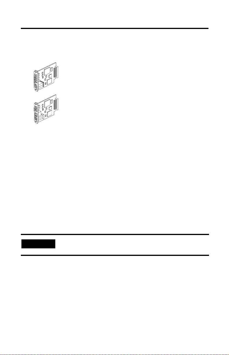
Set the Node Address
You must set two switch assemblies to configure the daughtercard with its unique
network address. Figure 1 (next page) shows the location of the switches. These
switches are read on powerup to establish the network address of the card.
Set the node address to a value between 1 and 99. For optimum throughput, assign
addresses to your ControlNet nodes in a sequential order starting with 01.
Node address 00 is not a valid ControlNet address. You should only use node
address 00 if the product that uses the ControlNet daughtercard has the ability to set
the node address using the host device interface.
This feature is typically used on products that do not provide easy custom er access
to the node address switches. If you set the node address switch to 00, it lets the
host in which the daughtercard resides set the node address, rather than letting the
daughtercard read the node address from the switch settings.
Publication 1788-IN005A-EN-P - March 2001
Page 7

Figure 1 -- Set the Node Address
I/O
Status
channel A connector
channel A connector
channel B connector
LED
Network Status Indicators (A and B)
ControlNet Daughtercard 7
Node Address
Module
NAP
Status LED
Network Status Indicators (A and B)
10’s
Switches
0’s
1788-CNF
1788-CNFR
31155
Install the Card
Due to wide variation in available host devices, we cannot provide specific
installation instructions in this document. For instructions on how to install the
daughtercard in a host device, refer to the user manual for the particular host
device.
IMPORTANT
WARNING
Do not install or remove the daughtercard while the host is
under power.
Inserting or removing the module while host power is on may
cause an electrical arc. This could cause an explosion in
hazardous location installations. Be sure that power is removed
or the area is nonhazardous before proceeding.
ÿ
Publication 1788-IN005A-EN-P - March 2001
Page 8

8 ControlNet Daughtercard
яюэьыъщшщччщцхфутссщуръщптыо
42822
42823
Connect the Card to the Netwo rk
After you have installed the card, you can connect it to the network. You must
connect the card to the network using an approved ControlNet fiber cable such as
one listed below:
• 1786-FS10 (10m cable assembly)
• 1786-FS20 (20m cable assembly)
• 1786-FS60 (60m cable assembly)
• 1786-FS100 (100m cable assembly)
• 1786-FS200 (200m cable assembly)
• 1786-FS300 (300m cable assembly)
For more fiber cable options, refer to the ControlNet Fiber Media Planning and
Installation Guide, publication CNET-IN001A-EN-P.
Publication 1788-IN005A-EN-P - March 2001
Page 9

ControlNet Daughtercard 9
Connect to the Network Using a Fiber Cable
1. Remove and save the protective caps from the ControlNet daughtercards.
2. Connect the fiber cable connector to the module’s connector.
2
1
42821
тюыюшэщчфъщяюсъыщрпуьхъщопыщнюмлпыущкмъыцчюпш
IMPORTANT
The zipcord uses a duplex cable. Duplex cables use a single cable that contains two
separate fibers, one for transmit and one for receive.
To prevent inadvertent reversal of the trunk cable connections
(resulting in incorrect status displays), check the drop cable for a
label indicating the attached cable before you make your
connection.
Publication 1788-IN005A-EN-P - March 2001
Page 10

10 ControlNet Daughtercard
To wire the module:
• Hold down the latch and insert the Channel A zipcord connector into the
duplex socket until the pins and latch lock into place (see the illustration
below).
Make sure you insert the blue pin (receive) of the z ipcord connector into the
left Rx and the black pin (transmit) into the right Tx socket.
If your network supp orts Connect the fiber cable
nonredundant media
(1788-CNF or -CNFR)
redundant media
(1788-CNFR)
to the channel A co nnector on the module
(channel B on t h e 1788-CNFR is not use d.)
1
from trunk-cable A to channel A on the 178 8-CNFR and from
trunk-cable B to channel B on the 1788-CNFR.
1. Rockwell Automation recommends using channel A for non-redundant media.
Figure 3 -- Example of ControlNet Network Topology
A
Rx
Tx
1786-RPA 1786-RPFS1786-RPA 1786-RPFS1786-RPA
Fiber segment 1
XT terminator
1786-RPFS
CH1
Rx
CH2
Rx
Tx
Fiber segment 2
CH1
CH2 CH2
Tx
Rx
Tx
Rx
Tx
CH1
Rx
Fiber segment 3
XT terminator
Coax segment 2
Tx
Rx
Tx
Coax segment 1
example ControlNet Node
IMPORTANT
It is not necessary to install nodes on coax segments. If you are
only using the repeaters to extend, then install a 75-Ω terminator
(1786-XT) on the BNC coax connector on the fiber repeater
adapter (1786-RPA). This should be done t o al l repeaters that are
not connected to coax segments.
Publication 1788-IN005A-EN-P - March 2001
example ControlNet Node
ACN
42834
Page 11

ControlNet Daughter car d 11
When you connect the daughtercard to a ControlNet network, you should also refer
to the ControlNet Fiber Media Planning and Installation Guide, publication
CNET-IN001A-EN-P.
See page 13 for information about status indicators.
IMPORTANT
If you use a non-redundant cable system, all ControlNet devices
must be on the same channel, we recommend channel A.
Connect to the Network Using a 1786-CP Cable
Use the following wiring diagram to connect the programming terminal to the
network using a 1786-CP cable.
Figure 6 -- Connect to the Network via the 1788-CNF NAP
Any ControlNet
interface card
1786-CP cable
1
The 1786-CP cable can be plugged into any ControlNet product’s NAP (Network Access Port) to provide
programming capability on the ControlNet network. A programming terminal connected through this
cable is counted as a node and must have a unique address.
ATTENTION
ÿ
Use the 1786-CP cable when you connect a programming
terminal to the network through the NAP port; using another
cable could result in possible network failures or product
damage.
1
31074-M
WARNING
ÿ
IMPORTANT
If you connect or disconnect the ControlNet NAP cable with
power applied to this module or any device on the network,
an electrical arc can occur. This could cause an explosion in
hazardous location installations. Be sure that power is
removed or the area is nonhazardous before proceeding.
The NAP is only available on the 1788-CNF. It is not available on
the 1788-CNFR.
Publication 1788-IN005A-EN-P - March 2001
Page 12

12 ControlNet Daughtercard
Wiring for the 1786-CP Connector Cable
Connector 1 Connector 2
Wire
Number
1 ISO-GND Isolated Ground 1 ISO-GND Isolated Ground
2 N.C. No Connection 2 N.C. No Connection
3 PTTX-H Transmit Data High 3 PTRX-H Receive Data High
4 PTTX-L Transmit Data Low 4 PTRX-L Rec eive Data Lo w
5 PTRX-L Receive Data Low 5 PTTX-L Transmit Data Low
6 PTRX-H Receive Data High 6 PTTX-H Transmit Data High
7 N.C. No Connection 7 N.C. No Connection
8 ISO-GND Isolated Ground 8 ISO-GND Isolated Ground
Signal
Mnemonic
Signal
Name
Wire
Number
Signal
Mnemonic
Signal
Name
Daughtercard Performance
Due to wide variation in available host devices, we cannot provide specific
performance capabilities in this document. For information concerning host/
daughtercard performance characteristics, refer to the user manual for the p articular
host device.
Publication 1788-IN005A-EN-P - March 2001
Page 13

ControlNet Daughter car d 13
Troubleshoot with the Status Indicators
Status indicators provide information about the card and the network when you are
connected via the fiber connectors. The following definitions and tables outline the
possible states, explains what each state means to you, and indicates what action
you should take, if any, to correct that state.
Definition of terms:
• steady - indicator is on continuously in the defined state.
• alternating - the two indicators alternate between the two defined states at
the same time (applies to both indicators when viewed together); the two
indicators are always in opposite states, out of phase.
• flashing - the indicator alternates between the two defined states (applies to
each indicator viewed independent of the other); if both indicators are
flashing, they flash together, in phase.
IMPORTANT
Keep in mind that the Module Status indictor reflects the module
state, e.g., self-test, firmware update, normal operation but no
connection established, etc. The network status LEDs, A and B,
reflect network status. Remember that the host is able to engage
in local messaging with the card although it is detached from the
network. Therefore, the Module Status LED is flashing green if
the host has successfully started the card. Note, however, that
until the host removes reset, all LEDs on the daughtercard will
remain off.
Publication 1788-IN005A-EN-P - March 2001
Page 14

14 ControlNet Daughtercard
Table 1: Module and I/O Status Indicators for 1788 -CNF
Indicator Color Probable Cause(s) Recommended Action
Module
Status
(MS)
I/O
Status
(I/O)
Off
Steady
Red
Flashing
Red
(Minor
fault)
Flashing
Green
Steady
Green
Flashing
Red/
Green
Always
Off
•No power
•Host is faulted
•Host is holding daughtercard
in reset
Major fault
Firmware update in progress No action required (firmware update in progress).
Node address switch change
Invalid module firmware
Duplicate node address
Node address switch set to 00 Host must set valid node address.
No connections established No action is required.
Connections established No action is required.
Self-test
•Check the power supply.
•Ensure that the daughtercard is f irmly seated in the
slot.
•Cycle power. If the indicator remains off, replace the
daughtercard or the host.
There is a hardware fault with the module. Cycle
power. If the problem persists, replace the
daughtercard.
The daughtercard’s node address switches may have
been changed since power-up. Change the node
address switches back to the original setting. The
module will continue to operate properly.
Update module firmware with ControlFlash Update
utility.
The daughtercard’s node address duplicates that of
another device. Remove power, change the node
address to a unique setting, then apply power.
The module is performing self-diagnostics. W ait br iefly
to see if problem corrects itself. If problem persists,
check the h ost. If the d aughtercard cannot
communicate with the host, it may remain in self-test
mode.
No action is required. This LED is on during the LED
portion of the self-tests.
IMPORTANT
The Module Status and I/O Status indicators are only available on
the 1788-CNF.
Publication 1788-IN005A-EN-P - March 2001
Page 15

ControlNet Daughter car d 15
Table 2: Network Status Indicators
Indicator Color Probable Cause Recommended Action
Off Channel disabled Program network for redundant media, if required.
A or B
(viewed
separately)
A and B
(viewed
together)
Steady
Green
Flashing
Green/Off
Flashing
Red/Off
Flashing
Red/Green
Off
Steady Red Faulted unit
Alternating
Red/Green
Alternating
Red/Off
Normal operation No action is required.
Temporary network errors None, unit will self-correct.
Node is not configured to
go on line
Media fault
No other nodes present on
network
Incorrect network
configuration
See the MS indicator for
additional i nformation
Make sure the configuration keeper node is present
and working.
Check media for broken cables, loose connectors,
missing terminators, etc.
If condition persists, refer to ContolNet Cable
Planning and Installation Manual, publication
1786-6.2.1.
Add other no des to the net w ork.
Cycle power or reset unit. If fault persists, contact
your Rockwell Automation representative or
distributor.
No action is required or apply power.
Cycle power or reset unit. If fault persists, contact
your Rockwell Automation representative or
distributor.
Self-test No action is required.
Incorrect node
configuration
Check network address and other ControlNet
configuration parameters.
Publication 1788-IN005A-EN-P - March 2001
Page 16

16 ControlNet Daughtercard
Hazardous Location information
The following information applies when operating this equipment in
hazardous locations:
Products marked “CL I, DIV 2, GP A, B, C, D” are suitable for use in Class I Division
2 Groups A, B, C, D, Hazardous Locations and nonhazardous locations only. Each
product is supplied with markings on the rating nameplate indicating the hazardous
location temperature code. When combining products within a system, the most
adverse temperature code (lowest “T” number) may be used to help determine the
overall temperature code of the system. Combinations of equipment in your system
are subject to investigation by the local Authority Having Jurisdiction at the time
of installation.
WARNING
ÿ
EXPLOSION HAZARD
• Do not disconnect equipment unless power has been
removed or the area is known to be nonhazardous.
• Do not disconnect connections to this equipment unless
power has been removed or the area is known to be
nonhazardous. Secure any external connections that mate
to this equipment by using screws, sliding latches, threaded
connectors, or other means provided with this product.
• Substitution of components may impair suitability for Class
I, Division 2.
• If this product contains batteries, they must only be
changed in an area known to be nonhazardous.
Publication 1788-IN005A-EN-P - March 2001
Page 17

ControlNet Daughter car d 17
Informations sur l’utilisation de cet équipement en environnements
dangereux :
Les produits marqués « CL I, DIV 2, GP A, B, C, D » ne conviennent qu’à une
utilisation en environnements de Classe I Divisi on 2 G roupes A, B, C , D dangereux
et non dangereux. Chaque produit est livré avec des marquages sur sa plaque
d’identification qui indiquent le code de température pour les environnements
dangereux. Lorsque plusieurs produits sont combinés dans un système, le code de
température le plus défavorable (code de température le plus faible) peut être
utilisé pour déterminer le code de température global du système. Les
combinaisons d’équipements dans le système sont sujettes à inspection par les
autorités locales qualifiées au moment de l’installation.
AVERTISSEMENT
ÿ
RISQUE D’EXPLOSION
• Couper le courant ou s’assurer que l’environnement est
classé non dangereux avant de débrancher l’équipement.
• Couper le courant ou s’assurer que l’environnement est
classé non dangereux avant de débrancher les connecteurs.
Fixer tous les connecteurs externes reliés à cet équipement
à l’aide de vis, loquets coulissants, connecteurs filetés ou
autres moyens fournis avec ce produit.
• La substitution de composants peut rendre cet équipement
inadapté à une utilisation en environnement de Classe 1,
Division 2.
• S’assurer que l’environnement est classé non dangereux
avant de changer les piles.
Publication 1788-IN005A-EN-P - March 2001
Page 18

18 ControlNet Daughtercard
Specifications
Characteristic Value
Power Requirements
Conductor
Environmental Sp ec i f i cations
Temperature
Weight 0.1 kg (0.2 lb.)
1
1788-CNF: 5V dc @ 440 mA (maximum)
1788-CNFR: 5V dc @ 450 mA (maximum)
Category 2
This industria l cont ro l equ ipmen t is i nten de d to oper ate i n a Pol luti on D egree
2 environment, in overvoltage category II applications, (as defined in IEC
publication 664A) at altitudes u p to 2000 mete rs without de ratin g. Also refer
to the user manual for your host device.
This product is suitable for application in equipment that is rated 0 to 60
o
(32 to 140
immediately surrounding this
2
F) maximum. It is acceptable for the ambient slot temperature
product to reach 85oC (185oF) maximum.
UL Recognized Component Industrial Control Equipment
Certified component Process Control Equipment
Certified component Class I, Division 2, Group A, B, C, D
o
C
Agency Certifications
When product it marked:
Marked for all applicable directives
Marked for all applicable acts
N223
ControlNet Internationa l
Conformance Tested
1
To comply with UL and CSA restrictions, this equipment must be powered from a source compliant with the
following: Class 2 or Limited Voltage/Current, as defined in UL 508 Seventeenth Edition Section 32; and
Separated Extra-Low Voltage (SELV), as defined in CSA C22.2 no. 1010, Annex H.
2
Refer to publication 1770-4.1, Industrial Automation Wiring and Grounding Guidelines.
Publication 1788-IN005A-EN-P - March 2001
Page 19

Notes:
ControlNet Daughter car d 19
Publication 1788-IN005A-EN-P - March 2001
Page 20

Allen-Bradley is a trademark of Rockwell Automation.
ControlNet is a trademark of ControlNet International.
Publication 1788-IN005A-EN-P - March 2001 PN 957345-78
© 2001 Rockwell International Corporation. Printed in the U.S.A.
 Loading...