

Page 1
Installation Instructions
ControlNet Fiber-optic Ring Repeater
Modules
Catalog Numbers 1786-RPFRL/B, 1786-RPFRXL/B
Topic Page
Important User Information 2
Environment and Enclosure 3
North American Hazardous Location Approval 4
Fiber-optic Safety Statements 5
About Fiber Topology 8
Mount the Fiber Modules 11
Choose Fiber-optic Cable for the Module 19
Connect the Cable Between the Repeater Modules 24
Interpret the Status Indicators 28
Specifications 33
Additional Resources 37
About the Module
The ControlNet Fiber-optic Ring Repeater module supports fiber media
redundancy by using a ring topolog y. The fiber-optic technology permits long
(1786-RPFRL/B module) or very long (1786-RPFRXL/B module)
transmission ranges. Both modules provide optimum protection against EMI
effects along the transmission link and at the repeaters themselves. The fiber link
provides ground isolation between nodes and is less susceptible to noisy
environments than traditional copper media.
Page 2
2 ControlNet Fiber-optic Ring Repeater Modules
Important User Information
Solid-state equipment has operational characteristics differing from those of electromechanical
equipment. Safety Guidelines for the Application, Installation and Maintenance of Solid State Controls
(Publication SGI-1.1
http://www.rockwellautomation.com/literature/
solid-state equipment and hard-wired electromechanical devices. Because of this difference, and also
because of the wide variety of uses for solid-state equipment, all persons responsible for applying this
equipment must satisfy themselves that each intended application of this equipment is acceptable.
In no event will Rockwell Automation, Inc. be responsible or liable for indirect or consequential damages
resulting from the use or application of this equipment.
The examples and diagrams in this manual are included solely for illustrative purposes. Because of the
many variables and requirements associated with any particular installation, Rockwell Automation, Inc.
cannot assume responsibility or liability for actual use based on the examples and diagrams.
No patent liability is assumed by Rockwell Automation, Inc. with respect to use of information, circuits,
equipment, or software described in this manual.
Reproduction of the contents of this manual, in whole or in part, without written permission of Rockwell
Automation, Inc., is prohibited.
Throughout this manual, when necessary, we use notes to make you aware of safety considerations.
available from your local Rockwell Automation sales office or online at
WARNING: Identifies information about practices or circumstances that can cause an
explosion in a hazardous environment, which may lead to personal injury or death,
property damage, or economic loss.
ATTENTION: Identifies information about practices or circumstances that can lead to
personal injury or death, property damage, or economic loss. Attentions help you identify
a hazard, avoid a hazard and recognize the consequences.
SHOCK HAZARD: Labels may be on or inside the equipment, for example, drive or motor,
to alert people that dangerous voltage may be present.
) describes some important differences between
BURN HAZARD: Labels may be on or inside the equipment, for example, drive or motor,
to alert people that surfaces may reach dangerous temperatures.
IMPORTANT Identifies information that is critical for successful application and understanding of the
product.
Rockwell Automation Publication 1786-IN003D-EN-P - April 2011
Page 3

ControlNet Fiber-optic Ring Repeater Modules 3
Environment and Enclosure
ATTENTION: This equipment is intended for use in a Pollution
Degree 2 industrial environment, in overvoltage Category II
applications (as defined in IEC 60664-1), at altitudes up to 2000 m
(6562 ft) without derating.
This equipment is considered Group 1, Class A industrial equipment
according to IEC/CISPR 11. Without appropriate precautions, there
may be difficulties with electromagnetic compatibility in residential
and other environments due to conducted and radiated disturbances.
This equipment is supplied as open-type equipment. It must be
mounted within an enclosure that is suitably designed for those
specific environmental conditions that will be present and
appropriately designed to prevent personal injury resulting from
accessibility to live parts. The enclosure must have suitable
flame-retardant properties to prevent or minimize the spread of flame,
complying with a flame spread rating of 5VA, V2, V1, V0 (or
equivalent) if non-metallic. The interior of the enclosure must be
accessible only by the use of a tool. Subsequent sections of this
publication may contain additional information regarding specific
enclosure type ratings that are required to comply with certain
product safety certifications.
In addition to this publication, see the following:
• Industrial Automation Wiring and Grounding Guidelines,
publication 1770-4.1
• NEMA Standard 250 and IEC 60529, as applicable, for explanations
of the degrees of protection provided by enclosures.
, for additional installation requirements
Rockwell Automation Publication 1786-IN003D-EN-P - April 2011
Page 4
4 ControlNet Fiber-optic Ring Repeater Modules
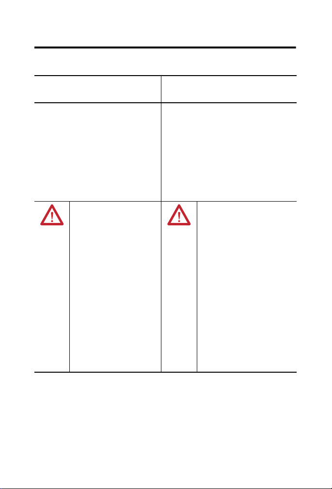
North American Hazardous Location Approval
The following information applies
when operating this equipment in
hazardous locations.
Products marked "CL I, DIV 2, GP A, B, C, D" are
suitable for use in Class I Division 2 Groups A, B, C,
D, Hazardous Locations and nonhazardous
locations only. Each product is supplied with
markings on the rating nameplate indicating the
hazardous location temperature code. When
combining products within a system, the most
adverse temperature code (lowest "T" number) may
be used to help determine the overall temperature
code of the system. Combinations of equipment in
your system are subject to investigation by the
local Authority Having Jurisdiction at the time of
installation.
WARNING:
Explosion Hazard -
•Do not disconnect equipment
unless power has been removed
or the area is known to be
nonhazardous.
•Do not disconnect connections to
this equipment unless power has
been removed or the area is
known to be nonhazardous.
Secure any external connections
that mate to this equipment by
using screws, sliding latches,
threaded connectors, or other
means provided with this product.
•Substitution of components may
impair suitability for Class I,
Division 2.
•If this product contains batteries,
they must only be changed in an
area known to be nonhazardous.
Informations sur l’utilisation de cet
équipement en environnements
dangereux.
Les produits marqués "CL I, DIV 2, GP A, B, C, D" ne
conviennent qu'à une utilisation en environnements
de Classe I Division 2 Groupes A, B, C, D dangereux et
non dangereux. Chaque produit est livré avec des
marquages sur sa plaque d'identification qui indiquent
le code de température pour les environnements
dangereux. Lorsque plusieurs produits sont combinés
dans un système, le code de température le plus
défavorable (code de température le plus faible) peut
être utilisé pour déterminer le code de température
global du système. Les combinaisons d'équipements
dans le système sont sujettes à inspection par les
autorités locales qualifiées au moment de
l'installation.
AVERTISSEMENT:
Risque d’Explosion –
•Couper le courant ou s'assurer que
l'environnement est classé non
dangereux avant de débrancher
l'équipement.
•Couper le courant ou s'assurer que
l'environnement est classé non
dangereux avant de débrancher les
connecteurs. Fixer tous les
connecteurs externes reliés à cet
équipement à l'aide de vis, loquets
coulissants, connecteurs filetés ou
autres moyens fournis avec ce
produit.
•La substitution de composants peut
rendre cet équipement inadapté à
une utilisation en environnement de
Classe I, Division 2.
•S'assurer que l'environnement est
classé non dangereux avant de
changer les piles.
Rockwell Automation Publication 1786-IN003D-EN-P - April 2011
Page 5
ControlNet Fiber-optic Ring Repeater Modules 5
Prevent Electrostatic Discharge
ATTENTION: This equipment is sensitive to electrostatic
discharge, which can cause internal damage and affect normal
operation. Follow these guidelines when you handle this
equipment:
• Touch a grounded object to discharge potential static.
• Wear an approved grounding wriststrap.
• Do not touch connectors or pins on component boards.
• Do not touch circuit components inside the equipment.
• Use a static-safe workstation, if available.
• Store the equipment in appropriate static-safe packaging when
not in use.
Fiber-optic Safety Statements
ATTENTION: Laser light can damage your eyes. Laser light is
invisible. Looking at it directly does not cause pain. The iris of the
eye will not close involuntarily as when you view a bright light.
Consequently, serious damage to the retina of the eye is possible.
Never look into the end of a fiber when it may have a laser coupled to
it, or directly into fiber ports. Should accidental eye exposure to laser
light be suspected, get an eye examination immediately.
ATTENTION: Class 1 laser product. Laser radiation is present
when the system is open and interlocks bypassed. Only trained and
qualified personnel should be allowed to install, replace, or service
this equipment.
Rockwell Automation Publication 1786-IN003D-EN-P - April 2011
Page 6
6 ControlNet Fiber-optic Ring Repeater Modules
TIP
IMPORTANT
WARNING: Hazardous areas require the use of specially designed
products. Only when the product is marked accordingly (see the
product ID label) it may be used in Class I Division 2 hazardous
environments. Rockwell Automation provides similar products that
are intrinsically safe and are suitable for more hazardous
environments. Use the appropriate products that are designed for
the specific hazardous environments that your installation requires.
In intrinsically-safe applications, consult with your local safety
coordinator because you need specific products on both ends of the
fiber link. Refer to the ControlNet EX Media Planning and
Installation Manual, publication CNET-IN003
You must use an adapter module (1786-RPA/B) with the
1786-RPFRL/B or 1786-RPFRXL/B modules to provide power to all
repeaters, and control the flow of data from one repeater to
the next.
The distance between repeaters that can be supported is
dependent on the quality of the fiber, number of splices, and
connectors. The total loss of the fiber link must be less than
15 dB for the 1786-RPFRL/B module and 10.5 dB for the
1786-RPFRXL/B module.
The total size of the ring or length of the copper and fiber
ControlNet network is limited by the ControlNet protocol to
20 km or less. Refer to Determine Maximum Network Length
21 for more information.
on page
To determine the maximum distance between any two fiber
modules, refer to the table on page
.
19.
Rockwell Automation Publication 1786-IN003D-EN-P - April 2011
Page 7
ControlNet Fiber-optic Ring Repeater Modules 7
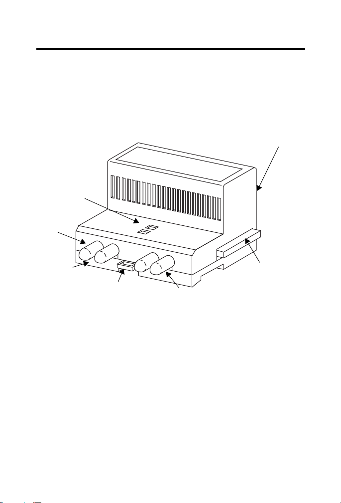
Relay Contact Connector (not shown)
42546
Right-side
Backplane
Connector
with
Protective
Cover
Both sides of the module contain a backplane connector.
Channel 2 Fiber Port
Module Locking Tab
Channel 1 Fiber Port
Protective
Caps
Indicators
The 1786-RPFRL/B and 1786-RPFRXL/M modules provide the following:
• Two f ib er cha nne ls
• Activity status indicators for each fiber channel
• Relay contact connector for communication and system status
Figure 1- Module Components
Rockwell Automation Publication 1786-IN003D-EN-P - April 2011
Page 8

8 ControlNet Fiber-optic Ring Repeater Modules
About Fiber Topology
The 1786-RPFRL/B or 1786-RPFRXL/B long or extra-long modules can be
used to create a redundant optical link between segments. When used in a ring
topology, a single media failure between any two repeater modules in a ring will
not impact the communication link.
The repeaters detect the failure of an optical link. When a failure occurs, the
affected channel port status indicator will be one of the following:
• Red, indicating a faulty link
• Flashing green/off, indicating no network activity is present
Refer to Interpret the Status Indicators on page
In addition, a relay contact connector on the 1786-RPFRL/B and
1786-RPFRXL/B modules indicates a remote faulty link. See page
information on the relay contact connector.
We recommend that you install the duplex optical cables of the two optical
channels along different routes. For more information on cabling, refer to
the ControlNet Fiber Media Planning and Installation Guide,
publication CNET-IN001
The fiber repeater consists of the following:
• A 1786-RPA/B repeater adapter
• Up to two 1786-RPFRL/B or 1786-RPFRXL/B long or extra-long fiber
repeater modules
• Up to four 1786-RPCD copper fiber repeater modules
• Up to four 1786-RPFS or 1786-RPFM short- or medium-distance fiber
repeater modules
.
28 for more information.
32 for more
Rockwell Automation Publication 1786-IN003D-EN-P - April 2011
Page 9

ControlNet Fiber-optic Ring Repeater Modules 9
IMPORTANT
The maximum number of repeater modules (in any combination) you can use in
a configuration is dependent on the current draw of each repeater module. Total
current draw supplied by the 1786-RPA/B repeater adapter cannot exceed
1.6 A @ 5V DC.
In addition to using the fiber repeater in a ring topology, you can do the
following:
• Extend the total length of your segment
• Create a point-to-point or star configuration (multiple directions from
one point)
• Provide electrical isolation and immunity to interference
• Use in hazardous areas
The number of fiber repeaters and cable length total limit depends on your
network topology.
Example Topology Application
See page 10 for an example topology.
For more information on topology application rules in relation to fiber rings,
refer to the ControlNet Fiber Media Planning and Installation Guide,
publication CNET-IN001
You cannot have media redundancy if you have a closed loop ring
installation anywhere in the network. You may use the
1786-RPFRL/B, 1786-RPFRXL/B, 1786-RPFM, or 1786-RPFS
modules in a linear fiber topology.
Do not mix fiber repeater modules to achieve a ring topology and
1786-RPFM modules to achieve a redundant media topology in
one configuration.
For additional topology configurations, refer to Allowable
Configurations When Using Repeaters in a Ring Topology on
ControlNet, Knowledgebase Technical Note ID 32215
.
.
Rockwell Automation Publication 1786-IN003D-EN-P - April 2011
Page 10
10 ControlNet Fiber-optic Ring Repeater Modules
TIP
1786-RPA
1786-RPFR(X)L
1786-RPFR(X)L
1786-RPA
CH1 CH2
CH1 CH2
1786-RPA
1786-RPFR(X)L
1786-RPA
1786-RPFR(X)L
CH1 CH2
CH1 CH2
RxTxRx
Tx
RxTxRx
Tx
Rx
Tx
Rx
Tx
Rx
Tx
Rx
Tx
1794-ACNR15
1794-ACNR15
1794-ACNR15
31237-M
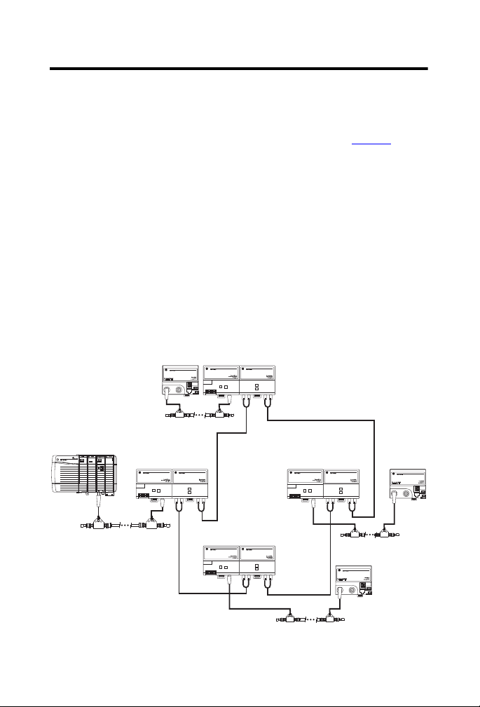
On all fiber repeater modules, the leftmost connector is the RX (Receive) port;
the rightmost connector is the TX (Transmit) port.
Fiber-optic Ring Topology
Use this configuration for long distances. A fiber-optic ring may contain as many
as 20 member modules. These member modules (four shown in Figure 2
include the following:
• 1786-RPA/B repeater adapter module
• 1786-RPFRL/B long-distance ring repeater module
• 1786-RPFRXL/B extra long-distance ring repeater module
You cannot exceed 20 repeater modules in a series. If a ring is
broken, whether accidentally or on purpose for testing, the
configuration then becomes linear and the number of repeaters
depends on where the ring is broken. Most likely you will have as
many repeaters as in the original ring, such as the four shown in
Figure 2.
Figure 2 - Fiber Ring Topology Example
)
Rockwell Automation Publication 1786-IN003D-EN-P - April 2011
Page 11
ControlNet Fiber-optic Ring Repeater Modules 11
TIP
ATTENTION: Be certain that the adapter and repeater modules
are secured together with DIN rail anchors. Failure to do so may
result in the loss of communication and/or cause damage to the
modules.
The total number of modules that can be attached to the 1786-RPA/B
repeater adapter cannot exceed four or the total power consumption
of the modules cannot exceed 1.6 A @ 5V DC, whichever comes first.
The 1786-RPFRL/B and 1786-RPFRXL/B modules require 570 mA each,
therefore you can attach only two of these modules to a
1786-RPA/B repeater module.
If you exceed the module or power limit, you may cause damage to the
modules and repeater adapter.
Mount the Fiber Modules
This section explains how to mount the module.
Horizontal mounting is preferred. Vertical mounting is allowed.
We recommend that the 1786-RPA/B module be mounted at the
top if vertical mounting is chosen.
ATTENTION: This product is grounded through the DIN rail to
chassis ground. Use zinc plated yellow-chromate steel DIN rail to
assure proper grounding. The use of other DIN rail materials (for
example, aluminum or plastic) that can corrode, oxidize, or are poor
conductors, can result in improper or intermittent grounding.
Secure DIN rail to mounting surface approximately every 200 mm
(7.8 in.) and use end-anchors appropriately.
Rockwell Automation Publication 1786-IN003D-EN-P - April 2011
Page 12
12 ControlNet Fiber-optic Ring Repeater Modules
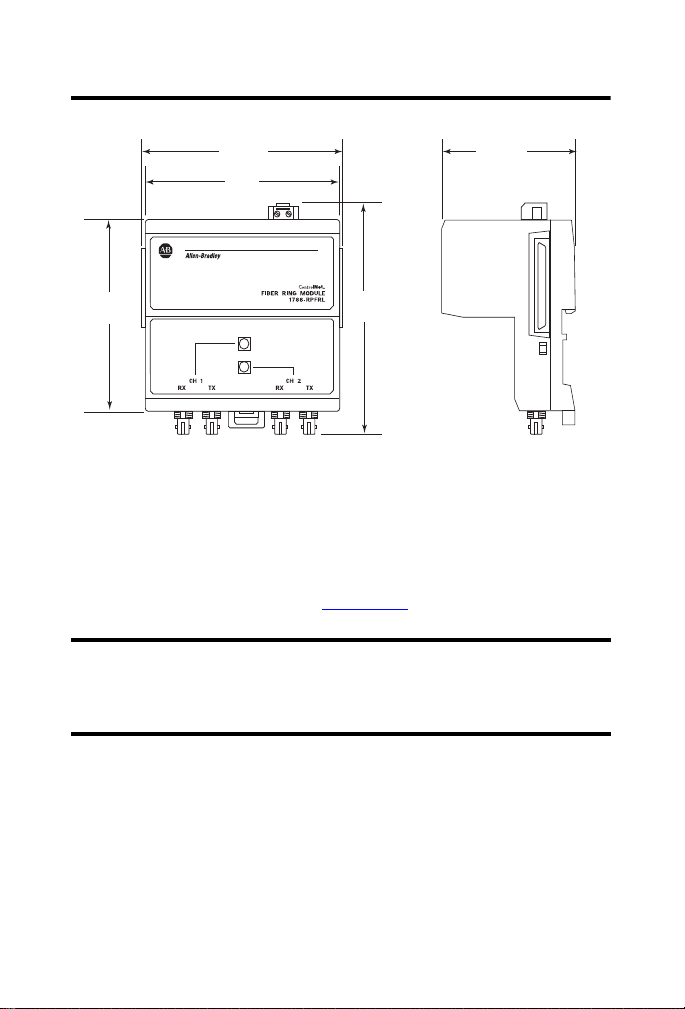
IMPORTANT
Dimensions are in mm (in.).
31532-M
107
(4.20)
69
(2.76)
100
(4.0)
90
(3.6)
108
(4.25)
Figure 3 - Mounting Dimensions
Horizontal mounting requirements are determined by using the following
formula:
RPA/B width + (4.2 inches x number of RPFR(X)L + 2 inches
For more information, see the ControlNet Modular Repeater Adapter
Installation Instructions, publication 1786-IN013
.
Maintain adequate separation from other equipment to
guarantee that ambient temperature is within the operating
range of this module. You must follow applicable separation
codes for safe operation.
Do these steps to mount a module.
1. Position the module on a 35 x 7.5 mm (1.38 x 0.30 in.) DIN rail,
Allen- Bradley part number 199- DR1; 46277- 3; EN 50022).
Rockwell Automation Publication 1786-IN003D-EN-P - April 2011
Page 13

ControlNet Fiber-optic Ring Repeater Modules 13
42542
42543
2. Hook the lip on the rear of the module onto the top of the DIN rail, and
rotate the module onto the rail.
3. Press the module onto the DIN rail until flush.
The locking tab should snap into position and lock the module to the
DIN rail.
4. If the module does not snap into position, use a screwdriver or similar
device to retract the locking tab while pressing the module flush onto the
DIN rail.
5. Release the locking tab to lock the module in place.
If necessary, push the locking tab to lock.
Rockwell Automation Publication 1786-IN003D-EN-P - April 2011
Page 14

14 ControlNet Fiber-optic Ring Repeater Modules
42632
WARNING: Removal and insertion under power (RIUP) is not
supported. These modules must be powered down while
connecting and disconnecting them from any interconnected
modules.
If you insert or remove the module while backplane power is on, an
electrical arc can occur. This could cause an explosion in hazardous
location installations.
Be sure that power is removed or the area is nonhazardous before
proceeding.
6. Remove the protective backplane cap as shown on page 18.
WARNING: When you connect or disconnect the removable
terminal block (RTB) with field side power applied, an electrical arc
can occur. This could cause an explosion in hazardous location
installations.
Be sure that power is removed or the area is nonhazardous before
proceeding.
7. Once the modules are attached to the DIN rail, slide them together to
mate the repeater adapter with the repeater module.
Rockwell Automation Publication 1786-IN003D-EN-P - April 2011
Page 15

ControlNet Fiber-optic Ring Repeater Modules 15
TIP
TIP
Use the key to open the ferrite. Remove the key and close the ferrite.
31530
Loop the Wire
Around the Ferrite
Twist the Wires
Install the Ferrites
This procedure explains how to set up a ferrite to reduce EMI interference. The
ferrite will be connected to the module’s relay contact connector.
If you are not planning to use the relay contact connector on the
module for system status, you do not need to install the ferrites.
1. Obtain 0.25... 2.5 mm2 (22...14 AWG) wire in a length sufficient for
your application.
You may want to choose a smaller wire gauge (for example,
0.25…0.823 mm
2
(22…18 AWG) with sufficient size and rating
to handle amperage requirements of the power supply to aid in
installation of the ferrite.
2. Twi st t he w ire s.
Rockwell Automation Publication 1786-IN003D-EN-P - April 2011
Page 16

16 ControlNet Fiber-optic Ring Repeater Modules
IMPORTANT
Connect Power Supply Wires
31528
Install the Ferrite at the Power Supply
Do these steps to attach the ferrite to the power supply of the
1786-RPA/B module.
1. Use the key supplied with the ferrite to open it.
Be careful not to damage the wires.
2. Form a loop with both wires (+ and -) approximately 100 mm (4 in.)
away from the power supply connector of the 1786-RPA/B module.
3. Loop the wires through the ferrite.
4. Close the ferrite.
Be careful not to damage the wires.
5. Strip approximately 6 mm (0.24 in.) of wire from the end that will
connect to the power supply connector on the 1786-RPA/B module.
6. Remove the power supply connector from the 1786-RPA/B module.
7. Install the stripped ends of the wires in the power supply connector on
the 1786-RPA/B module as shown below.
Rockwell Automation Publication 1786-IN003D-EN-P - April 2011
Do not use more than one ferrite per 1786-RPA/B module.
Page 17

ControlNet Fiber-optic Ring Repeater Modules 17
Connect the Ferrite Here
8. Reinsert the power supply connector into the 1786-RPA/B module.
Install the Ferrite at the Relay Contact Connector
1. Use the key to open the remaining ferrite.
2. Form a loop with both wires (+ and -) approximately 100 mm (4.0 in.)
away from the relay contact connector of the 1786-RPFRL/B or
1786-RPFRXL/B module.
3. Loop the wires through the ferrite.
4. Close the ferrite.
Be careful not to damage the wires.
5. Strip approximately 6 mm (0.24 in.) of wire from the end that will
connect to the relay contact connector on the 1786-RPFRL/B or
1786-RPFRXL/B module.
6. Remove the relay contact connector from the 1786-RPFRL/B or
1786-RPFRXL/B module.
7. Install the stripped ends of the wires in the relay contact connector on
the fiber repeater module as shown below.
8. Reinsert the relay contact connector into the 1786-RPFRL/B or
1786-RPFRXL/B module.
Rockwell Automation Publication 1786-IN003D-EN-P - April 2011
Page 18

18 ControlNet Fiber-optic Ring Repeater Modules
Protective
Backplane Cap
Protective Cap
9. Connect the fiber cable as described on page 26.
10. If you plan not to use a channel, attach a small section of fiber cable (or a
Simplex fiber loop) between the Receive port (RX) and the Transmit
Port (TX) of any unused fiber port to create a jumper.
Although not required for module operation, the jumper turns the
status indicators green and prevents the relay contact connector from
opening and indicating a failure.
Remove the Protective Caps
1. Remove the protective caps from the fiber ports that you are going to
use.
2. Save the caps for future use.
The left side of the module (not shown here) also contains a
backplane connector.
If you plan Then
To place the module in storage Keep the protective caps on the channels to
To connect another module to the right
backplane connector
Not to connect to the right backplane
connector
Rockwell Automation Publication 1786-IN003D-EN-P - April 2011
protect the unit from dust.
Remove the protective backplane cap and
save the cap for future use.
Leave the backplane cap on.
Page 19

ControlNet Fiber-optic Ring Repeater Modules 19
ATTENTION: Do not discard the end cap. Use this end cap to
cover the exposed interconnections on the last repeater module on
the DIN rail. Failure to do so could result in equipment damage or
injury from electric shock.
Choose Fiber-optic Cable for the Module
The type of fiber cable you choose to use depends on the network environment.
Consult your installation professional to determine the best type of cable to use
for your environmental conditions. Refer to the ControlNet Fiber Media
Planning and Installation Guide, publication CNET-IN001
Understand the Maximum Optical Power Budget
This table shows the maximum optical power budget available for different cable
types. Note that the 1786-RPFRL/B module cannot be used with
single-mode fiber.
Module Cable Type Optical Power Budget Termination Type
1786-RPFRL/B 62.5/125 µm,
1786-RPFRXL/B 62.5/125µ
multimode, 1300 nm,
graded index
m,
multimode, 1300 nm,
graded index
9/125 µ
m,
single mode, 1300 nm,
graded index
15 dB ST connectors,
10.5 dB
, for details.
plastic or ceramic;
no metal
connectors
See page
20 for formulas to determine your optical power budget.
Rockwell Automation Publication 1786-IN003D-EN-P - April 2011
Page 20

20 ControlNet Fiber-optic Ring Repeater Modules
EXAMPLE
The sample formulas in the example illustrate how you can determine the total
loss for fiber-optic cables in your system configuration. The values we use in the
formulas are typical: yours may vary, depending on your application.
Determining total loss for fiber-optic cables
The total loss of the fiber-optic cable between two modules must
not exceed the optical power budget. The total loss is the sum of
each connector loss plus the loss of the fiber plus the loss
associated with the splices in the system, if any. The total loss
can be determined as follows:
Total loss = [(loss per connector) x (the number of connectors)] +
[(loss per km of fiber) x (km of fiber)] + [(other losses)]
For example, with 2 connectors, each having 0.3 dB of loss,
10 km of multimode fiber with a loss of 1 dB/km, and no splices,
the total loss is 10.6 dB. See the following formula:
Total loss = [(0.3 dB x 2) + (1 dB/km x 10 km)]
Total loss = 10.6 dB
This fiber-optic cable is acceptable for use between two
1786-RPFRL/B modules because the total loss is less than the
optical power budget of 15 dB. However, this cable could not be
used with the 1786-RPFRXL/B module because the total loss
exceeds the optical power budget of 10.5 dB.
Rockwell Automation Publication 1786-IN003D-EN-P - April 2011
Page 21

ControlNet Fiber-optic Ring Repeater Modules 21
TIP
Determine Maximum Network Length
The quality of the fiber cable determines the maximum distance between
modules in a networked system. The delay in the system (described in the
following table) determines the maximum length you can achieve with your
network.
The worst-case delay (between any nodes) must be less than 121 μs. This table
lists worst-case delays for physical layer components.
Table 1 -Worst-case Delay
Component Delay
Coaxial cable 4.17 ns/m
Fiber 5.01 ns/m
1786-RPA/B module 901 ns
1786-RPFM module 153 ns
1786-RPFS module 94 ns
1786-RPCD module 100 ns
1786-RPFRL/B
1786-RPFRXL/B modules
When determining the worst-case delay for your system,
consider how many components you want to use. You can use as
many as twenty fiber repeater modules in a ring or series as long
as you do not exceed the maximum network length, as
determined by the worst-case delay.
The maximum cable distance (that is, the longest route between
any two adjacent or non-adjacent nodes) is limited by the
ControlNet protocol to 20 km or less. Refer to Determine
Maximum Network Length on page
100 ns
21 for more information.
See Figure 4
on page 22 and the example on page 23 to understand how to
determine the worst-case delay for your system.
Rockwell Automation Publication 1786-IN003D-EN-P - April 2011
Page 22

22 ControlNet Fiber-optic Ring Repeater Modules
1786-RPA
1786-RPFR(X)L
1786-RPFR(X)L
1786-RPA
CH1 CH2
CH1 CH2
1786-RPA
1786-RPFR(X)L
1786-RPA
1786-RPFR(X)L
CH1 CH2
CH1 CH2
RxTxRx
Tx
RxTxRx
Tx
Rx
Tx
Rx
Tx
Rx
Tx
Rx
Tx
1794-ACNR15
1794-ACNR15
1794-ACNR15
31237-M
A
B
C
D
E
F
G
H
Node 1
Node 2
Node 3
Node 4
Figure 4 -Determine Worst-case Delay
Segment Length
A 200 m
B2 km
C10 m
D1 km
E20 m
F5 km
G20 m
H 200 m
Rockwell Automation Publication 1786-IN003D-EN-P - April 2011
Page 23

ControlNet Fiber-optic Ring Repeater Modules 23
EXAMPLE
Determining worst-case delay
To determine the worst-case delay in a ring topology, first
disregard the shortest fiber segment in the system.
In Figure 4
the 200 m fiber. Remove segment H. You will see that the
worst-case delay is now between nodes 1 and 2.
You must account for worst-case delays introduced by physical
media when setting up the media configuration screen in
RSNetWorx software. If too many components with too great a
delay are entered into RSNetWorx for ControlNet software, the
delay becomes too great for the bandwidth RSNetWorx software
has available. This affects system performance and limits
network length. If you do not account for all media components in
the worst-case delay path, erratic network operation will result.
Refer to the documentation supplied with RSNetWorx for
ControlNet software for more information.
This example shows you in a simple way how to account for
system delays. In this example, you enter the total length of all
media components between nodes 1 and 2 into RSNetWorx for
ControlNet software. The totals of the components between
nodes 1 and 2 are as follows, as specified in Tab le 1
Coax media delay: 200 m (A) + 20 m (G) = 220 m x 4.17 ns
Fiber media delay: 2 km (B) + 1 km (D) + 5 km (F) = 8 km x 5.01 ns
1786-RPA/B module delay: 1 (at node 1) + 1 (at node 3) +
1 (at node 4) +1 (at node 2) = 4 x 901 ns
1786-RPFRL/B or 1786-RPFRXL/B module: 1 (at node 1) +
1 (at node 3) + 1 (at node 4) +1 (at node 2) = 4 x 100 ns
In summary:
Worst-case delay = 220 x 4.17 + 8000 x 5.01 + 4 (901)
+ 4 (100) = 45 µs
This delay is acceptable because 45 µs is less than the maximum
allowable delay of 121 µs.
on page 22, the shortest segment is segment H, with
on page 21:
Rockwell Automation Publication 1786-IN003D-EN-P - April 2011
Page 24

24 ControlNet Fiber-optic Ring Repeater Modules
IMPORTANT
Set up the Network SMAX Parameter in RSNetWorx Software
You must set up the SMAX parameter in RSNetWorx for ControlNet software
to use with the 1786-RPFRL/B or 1786-RPFRXL/B module. The SMAX
parameter sets the maximum scheduled node address on a ControlNet network.
Refer to the documentation supplied with the RSNetWorx for ControlNet
software.
You must set the SMAX parameter at least one node number higher than the
highest used scheduled node number. For example, on a network with 49
scheduled nodes (with 49 being the highest used scheduled node number), you
must set SMAX to at least 50. In this example, node number 50 is an unused
scheduled node number.
When setting the SMAX parameter, you must allow one unused
scheduled node address. This unused node address must be the
highest available scheduled node number. Therefore, the
maximum usable node address when using the 1786-RPFRL/B or
1786-RPFRXL/B module is 98.
Connect the Cable Between the Repeater Modules
The following pages explain instructions for properly and safely connecting
fiber cable.
Rockwell Automation Publication 1786-IN003D-EN-P - April 2011
Page 25

ControlNet Fiber-optic Ring Repeater Modules 25
IMPORTANT
Terminate the Cable
Termination is the process of attaching connectors to the ends of fiber cable.
Follow these general instructions when terminating fiber cable.
ATTENTION: Safety glasses are required to protect your eyes
when you handle chemicals and cut fiber. Pieces of glass fiber are
very sharp and can easily damage the cornea of your eye.
Cleaved glass fibers are very sharp and can pierce the skin easily. Do
not let cut pieces of fiber stick to your clothing or drop in the work
area where they can cause injury later. Use tweezers to pick up cut or
broken pieces of the glass fibers and place them on a loop of tape
kept for that purpose alone. Keep your work area clean.
Be certain to follow the instructions that are provided by your
fiber termination kit manufacturer.
1. Organize your termination kit materials.
2. Reference your plan to be certain that you have enough supplies to make
the fiber connections and to terminate all used fiber cable ends.
3. Make a schedule for performing the connections.
4. Follow the assembly and safety procedures for your termination kit.
5. Place a dust cap (supplied in fiber cable kits) on the end of the connector.
ATTENTION: If this equipment is used in a manner not specified
by the manufacturer, the protection provided by the equipment
may be impaired.
Rockwell Automation Publication 1786-IN003D-EN-P - April 2011
Page 26

26 ControlNet Fiber-optic Ring Repeater Modules
TIP
TX
TXRX
RX
Connect the Cable
This section describes how to connect cables by using the tracer on the cable to
identify and follow the cable throughout your system.
A tracer is one of the two wires on the duplex cable that is one of
the following :
• Printed with the cable legend
• Ribbed
For further information on choosing cables and wiring your system, refer
to the ControlNet Fiber Media Planning and Installation Guide,
publication CNET-IN001
The instructions explain how to connect the cable between the fiber modules by
making a simple ‘criss-cross’ connection. To do this, you will connect the cables
between modules from the receive (RX) end of one channel to the transmit
(TX) end of the other module, as shown in the following diagram.
.
Channels 1 and 2 on the module are identical. Channel 1 of a
Do these steps to connect the cable.
module can be connected to either channel of another module.
1. Use the tracers on the cable to identify which cable is connected to the
receive (RX) port and which one to the transmit port (TX).
Rockwell Automation Publication 1786-IN003D-EN-P - April 2011
Page 27

ControlNet Fiber-optic Ring Repeater Modules 27
42550
2. Connect the receive port (RX) and transmit port (TX) at the
starting module.
3. Do the following to attach the cable connector to the module connector.
a. Align the key of the cable connector with the slot in the module
connector, and insert the connector into the RX port.
b. Push and twist the locking cap until the bayonet lug is locked into
place.
4. At the second module, connect the cables in reverse.
For example, tracer to TX port on module 1, non-tracer to RX port on
module 1: tracer to RX port on module 2, non-tracer to TX port
on module 2.
ATTENTION: Under certain conditions, viewing the optical port
may expose the eye to hazard. When viewed under some
conditions, the optical port may expose the eye beyond the
maximum permissible exposure recommendations.
Rockwell Automation Publication 1786-IN003D-EN-P - April 2011
Page 28

28 ControlNet Fiber-optic Ring Repeater Modules
TIP
Repeater Module Status Indicators
Repeater Adapter Status Indicators
1786-RPFRL/B1786-RPA/B
31216
Interpret the Status Indicators
Fiber repeaters receive status information from the repeater adapters. Because of
this, you should use the fiber repeater status indicators in conjunction with the
1786-RPA/B status indicators to diagnose an anomaly.
For status indicators for this module See
1786-RPA/B Table 2
1786-RPFRL/B and 1786-RPFRXL/B Table 3
In general, if the status indicators on the 1786-RPA/B module
are green, the fiber repeater module is operating properly.
For more information on the 1786-RPA/B module, refer to the ControlNet
Modular Repeater Adapter Installation Instructions, publication 1786-IN013
1786-RPA/B Status Indicators
The status indicators on the repeater adapter can be interpreted singly or
together. The following three tables list different combinations of status
indicators and their interpretations.
.
Rockwell Automation Publication 1786-IN003D-EN-P - April 2011
Page 29

ControlNet Fiber-optic Ring Repeater Modules 29
Table 2 -1786-RPA/B Repeater Adapter Module Status Indicators
If repeater adapter
indicator is
Alternating red/green The repeater adapter is
Solid red A jabber condition has
Off The repeater adapter is not
Solid green Error-free data is being
Flashing green/off Data with errors is
Flashing red/off Either no data is being
This means You should
being powered or reset.
occurred. Another node or
repeater on the network is
transmitting constantly.
powered or has failed.
recovered at the coax port
of the repeater adapter.
occasionally being
recovered at the coax port
of the repeater adapter.
received at the coax port of
the repeater adapter, or
data with a large number of
errors is being received at
the coax port of the
repeater adapter.
Do nothing. The repeater adapter
is operating properly.
Check the network and
components for proper operation.
Check the power input to the
repeater adapter for correct
voltage and polarity.
Do nothing. The repeater adapter
is operating properly.
This situation will normally
correct itself. If the situation
persists check the following:
• All BNC connector pins are
seated properly.
• All taps are Rockwell
Automation taps.
• All terminators are 75 Ω and
are installed at both ends.
• The coax cable has not
been grounded.
Check for the following:
• Broken cables.
• Broken taps.
• Missing segment terminators.
Rockwell Automation Publication 1786-IN003D-EN-P - April 2011
Page 30

30 ControlNet Fiber-optic Ring Repeater Modules
Channel 2 Status Indicator
Channel 1 Status Indicator
1786-RPFRL/B or 1786-RPRFRXL/B Status Indicators
Table 3 - Fiber Repeater Module Status Indicators
If the fiber repeater
module indicator is
Off Fiber repeater module is not
Green Fiber repeater module is
Flashing green/off No data activity on network. If the cable is attached, do
Rockwell Automation Publication 1786-IN003D-EN-P - April 2011
This means You should
connected to the power
supply.
running without network
errors.
Connect the repeater to the
power supply.
Do nothing. The fiber
repeater module is
operating properly.
the following:
• Ensure that the receive
(RX) channel is
connected to the
transmit (TX) channel on
both modules.
• Check for broken fiber.
Page 31

ControlNet Fiber-optic Ring Repeater Modules 31
Table 3 - Fiber Repeater Module Status Indicators
If the fiber repeater
module indicator is
Flashing red/off Module is powered, but not
Intermittent red As more data errors are
Red Excessive receive signal
This means You should
ready for operation. This
state should also occur
during module reset and last
for approximately
5 seconds.
detected the frequency of
the flashing red increases
until a solid red displays.
distortion.
Do nothing. The fiber
repeater module is
operating properly.
Check for proper operation.
Review these items:
• Be certain that you are
using the correct fiber
type for your module.
• Check fiber length and
attenuation to make sure
that it is within
specification.
• Replace the downstream
1786-RPFRL module on
the channel that is
having the intermittently
flashing red status
indicator.
• Be certain that your total
network length is not out
of specification.
• Be certain that SMAX is
correctly defined in the
RSNetWorx for
ControlNet software.
Rockwell Automation Publication 1786-IN003D-EN-P - April 2011
Page 32

32 ControlNet Fiber-optic Ring Repeater Modules
Relay Contact Connector
31531-M
1786-RPFRL/B or 1786-RPFRXL/B Relay Contact Connector
The fiber repeater module contains a single electromechanical relay for
communication and system status.
Table 4 -Relay Contact Connector Diagnostics
If Then
• No receive data is present at one or both
fiber-optic ports for more than 1300 ms
(that means if either Channel 1 or
Channel 2 status indicators are not solid
green, the fault relay will open.)
• The repeater is not connected to the
power supply.
Neither of the above two conditions
are met.
The relay contact is open.
The relay contact is closed.
Rockwell Automation Publication 1786-IN003D-EN-P - April 2011
Page 33

ControlNet Fiber-optic Ring Repeater Modules 33
Specifications
Technical Specifications - 1786-RPFRL/B, 1786-RPFRXL/B
Attribute 1786-RPFRL/B, 1786-RPFRXL/B
All supply voltages or voltage ranges Input: 570 mA @ 5V DC, max
Relay: 900 mA @ 30V DC, max resistive
Backplane power requirements 2.8 W (3.02 W, max)
Communication rate 5 Mbps
Mounting orientation Any mounting orientation
Relay contact connector voltage 30V DC, max
Relay contact connector current
consumption
1 mA, min; 900 mA, max
Relay contact load type Resistive only
Isolation voltage 50V (continuous), Basic insulation type,
Relay contacts to system
Optical power budget See the optical power budget table
Wire size 0.25... 2.5 mm2 (22...14 AWG) solid or
on page
19
stranded copper wire rated at 75 °C
(167 °F ), or greater, 1.2 mm (3/64 in.)
insulation max for relay connections
Wiring category 2 - on signal ports
Enclosure type rating None (open-style)
North American temp code T5
(1) Operational power is provided from the 1786-RPA/B module. For application within the U.S., supply
the 1786-RPA/B module from a power supply that is appropriately certified Class 2 per the definition
in the National Electrical Code, ANSI/NFPA 70, Article 725. For applications outside the U.S., supply
the 1786-RPA/B module from a safety extra low voltage (SELV) power supply. SELV output is built with
appropriate isolation to withstand single fault conditions. The output cannot exceed 30V rms, 42.4V
peak, or 60V DC under fault conditions.
(2) Use this Conductor Category information for planning conductor routing. Refer to Industrial
Automation Wiring and Grounding Guidelines, publication 1770-4.1
(1)
(2)
.
Rockwell Automation Publication 1786-IN003D-EN-P - April 2011
Page 34

34 ControlNet Fiber-optic Ring Repeater Modules
Environmental Specifications - 1786-RPFRL/B, 1786-RPFRXL/B
Attribute 1786-RPFRL/B, 1786-RPFRXL/B
Temperature, operating
IEC 60068-2-1 (Test Ad, Operating Cold),
IEC 60068-2-2 (Test Bd, Operating Dry Heat),
IEC 60068-2-14 (Test Nb, Operating Thermal
Shock)
Temperature, surrounding air, max 60 °C (140 °F)
Temperature, nonoperating
IEC 60068-2-1 (Test Ab, Unpackaged
Nonoperating Cold),
IEC 60068-2-2 (Test Bb, Unpackaged
Nonoperating Dry Heat),
IEC 60068-2-14 (Test Na, Unpackaged
Nonoperating Thermal Shock)
Relative humidity
IEC 60068-2-30 (Test Db, Unpackaged Damp
Heat)
Vibration
IEC60068-2-6 (Test Fc, Operating)
Shock, operating
0…60 °C (32…140 °F)
-40…85 °C (-40…185 °F)
5...95% noncondensing
5 g @ 10...500 Hz
30 g
IEC60068-2-27 (Test Ea, Unpackaged Shock)
Shock, nonoperating
IEC60068-2-27 (Test Ea, Unpackaged Shock)
Emissions
CISPR 11
ESD immunity
IEC 61000-4-2
Rockwell Automation Publication 1786-IN003D-EN-P - April 2011
50 g
Group 1, Class A
6 kV contact discharges
8 kV air discharges
Page 35

ControlNet Fiber-optic Ring Repeater Modules 35
Environmental Specifications - 1786-RPFRL/B, 1786-RPFRXL/B
Attribute 1786-RPFRL/B, 1786-RPFRXL/B
Radiated RF immunity
IEC 61000-4-3
EFT/B immunity
IEC 61000-4-4
Surge transient immunity
IEC 61000-4-5
Conducted RF Immunity
IEC 61000-4-6
10V/m with 1 kHz sine-wave 80% AM from
80…2000 MHz
10V/m with 200 Hz 50% Pulse 100% AM at
900 and 1890 MHz
1V/m with 1 kHz sine-wave 80% AM from
2000…2700 MHz
±4 kV at 5 kHz on signal ports
±1 kV line-line (DM) and ±2 kV line-earth
(CM) on signal ports
10V rms with 1 kHz sine-wave 80% AM
from 150 kHz…80 MHz
Rockwell Automation Publication 1786-IN003D-EN-P - April 2011
Page 36

36 ControlNet Fiber-optic Ring Repeater Modules
Certifications
Certification
c-UL-us
(4)
CE
(1)
- 1786-RPFRL/B, 1786-RPFRXL/B
(2)
(3)
1786-RPFRL/B, 1786-RPFRXL/B
UL Listed for Class I, Division 2 Group
A,B,C,D Hazardous Locations, certified for
U.S. and Canada. See UL File E194810.
European Union 2004/108/EC EMC
Directive, compliant with:
• EN 61326-1; Meas./Control/Lab.,
Industrial Requirements
• EN 61000-6-2; Industrial Immunity
• EN 61000-6-4; Industrial Emissions
• EN 61131-2; Programmable Controllers
(Clause 8, Zone A & B)
C-Tick Australian Radiocommunications Act,
compliant with:
• AS/NZS CISPR 11; Industrial Emissions
(1) When product is marked.
(2) See the Product Certification link at http://www.ab.com
and other certification details.
(3) To comply with UL restrictions, the relay connection must be powered from a source compliant with
Class 2 or Limited Voltage/Current.
(4) To comply with the CE Low Voltage Directive (LVD), the relay connection must be powered from a
source compliant with safety extra low voltage (SELV) or protected extra low voltage (PELV).
for Declarations of Conformity, Certificates,
Rockwell Automation Publication 1786-IN003D-EN-P - April 2011
Page 37

ControlNet Fiber-optic Ring Repeater Modules 37
Additional Resources
These documents contain additional information concerning related Rockwell
Automation products.
Resource Description
ControlNet Coax Taps Installation
Instructions, publication 1786-IN007
ControlNet Coax Media Planning and
Installation Guide, publication CNET-IN002
ControlNet Fiber Media Planning and
Installation Guide, publication CNET-IN001
Industrial Automation Wiring and
Grounding Guidelines,
publication 1770-4.1
You can view or download publications at
http://www.rockwellautomation.com/literature/. To order paper copies of
technical documentation, contact your local Rockwell Automation distributor
or sales representative.
Document contains procedures and
specifications for the installation of
ControlNet coaxial taps.
Document describes the components and
topologies for creating a ControlNet coax
media system.
Document describes the components and
topologies for creating a ControlNet fiber
media system.
Document contains more information on
proper wiring and grounding techniques.
Rockwell Automation Publication 1786-IN003D-EN-P - April 2011
Page 38

38 ControlNet Fiber-optic Ring Repeater Modules
Notes:
Rockwell Automation Publication 1786-IN003D-EN-P - April 2011
Page 39

Notes:
ControlNet Fiber-optic Ring Repeater Modules 39
Rockwell Automation Publication 1786-IN003D-EN-P - April 2011
Page 40

Rockwell Otomasyon Ticaret A.Ş., Kar Plaza İş Merkezi E Blok Kat:6 34752 İçerenköy, İstanbul, Tel: +90 (216) 5698400
Rockwell Automation Support
Rockwell Automation provides technical information on the Web to assist you in using its products. At
http://www.rockwellautomation.com/support/
technical and application notes, sample code and links to software service packs, and a MySupport feature
that you can customize to make the best use of these tools.
For an additional level of technical phone support for installation, configuration, and troubleshooting, we
offer TechConnect support programs. For more information, contact your local distributor or Rockwell
Automation representative, or visit http://www.rockwellautomation.com/support/
Installation Assistance
If you experience a problem within the first 24 hours of installation, please review the information that's
contained in this manual. You can also contact a special Customer Support number for initial help in getting
your product up and running.
United States or Canada 1.440.646.3434
Outside United States or
Canada
Use the Worldwide Locator
http://www.rockwellautomation.com/support/americas/phone_en.html
contact your local Rockwell Automation representative.
New Product Satisfaction Return
Rockwell Automation tests all of its products to ensure that they are fully operational when shipped from
the manufacturing facility. However, if your product is not functioning and needs to be returned, follow
these procedures.
United States
Outside United States
Contact your distributor. You must provide a Customer Support case number
(call the phone number above to obtain one) to your distributor to complete
the return process.
Please contact your local Rockwell Automation representative for the return
procedure.
, you can find technical manuals, a knowledge base of FAQs,
.
at
, or
Documentation Feedback
Your comments will help us serve your documentation needs better. If you have any suggestions on how to
improve this document, complete this form, publication RA-DU002
http://www.rockwellautomation.com/literature/
Allen-Bradley, Rockwell Software, Rockwell Automation, RSNetWorx for ControlNet, RSNetWorx, and TechConnect are
trademarks of Rockwell Automation, Inc.
Trademarks not belonging to R ockwell Automation are property of their respective companies.
.
Publication 1786-IN003D-EN-P - April 2011 PN-92666
Supersedes Publication 1786-IN003C-EN-P - February 2002 Copyright © 2011 Rockwell Automation, Inc. All rights reserved. Printed in the U.S.A.
, available at
 Loading...