

Page 1

Allen-Bradley
Stepper
Positioning
User
Assembly
(Cat. No. 1771–QA)
Manual
Page 2

Important User
Information
Because of the variety of uses for the products described in this
publication, those responsible for the application and use of this control
equipment must satisfy themselves that all necessary steps have been taken
to assure that each application and use meets all performance and safety
requirements, including any applicable laws, regulations, codes
and standards.
The illustrations, charts, sample programs and layout examples shown in
this guide are intended solely for example. Since there are many variables
and requirements associated with any particular installation, Allen-Bradley
does not assume responsibility or liability (to include intellectual property
liability) for actual use based upon the examples shown in this publication.
Allen-Bradley publication SGI–1.1, “Safety Guidelines For The
Application, Installation and Maintenance of Solid State Control”
(available from your local Allen-Bradley office) describes some important
differences between solid-state equipment and electromechanical devices
which should be taken into consideration when applying products such as
those described in this publication.
Reproduction of the contents of this copyrighted publication, in whole or
in part, without written permission of Allen–Bradley Company, Inc.
is prohibited.
Throughout this manual we make notes to alert you to possible injury to
people or damage to equipment under specific circumstances.
ATTENTION: Identifies information about practices or
circumstances that can lead to personal injury or death, property
damage or economic loss.
Attention helps you:
Identify a hazard.
Avoid the hazard.
Recognize the consequences.
Important: Identifies information that is especially important for
successful application and understanding of the product.
Important: We recommend you frequently backup your application
programs on appropriate storage medium to avoid possible data loss.
Page 3

Table of Contents
Introduction
Assembly and Installation
Chapter 1
Description 1–1. . . . . . . . . . . . . . . . . . . . . . . . . . . . . . . . . . . . . . . . .
Understand Compliance to European Union Directives 1–2. . . . . . . . . .
EMC Directive 1–2. . . . . . . . . . . . . . . . . . . . . . . . . . . . . . . . . . . . .
Low Voltage Directive 1–2. . . . . . . . . . . . . . . . . . . . . . . . . . . . . . . .
Chapter 2
General 2–1. . . . . . . . . . . . . . . . . . . . . . . . . . . . . . . . . . . . . . . . . . .
Input Considerations 2–1. . . . . . . . . . . . . . . . . . . . . . . . . . . . . . . . . .
Power Supply Considerations 2–2. . . . . . . . . . . . . . . . . . . . . . . . . . . .
I/O Power Supply 2–2. . . . . . . . . . . . . . . . . . . . . . . . . . . . . . . . . . .
Auxiliary Power Supply 2–2. . . . . . . . . . . . . . . . . . . . . . . . . . . . . . .
Stepper Translator and Power Supply 2–3. . . . . . . . . . . . . . . . . . . .
Stepper Motor 2–3. . . . . . . . . . . . . . . . . . . . . . . . . . . . . . . . . . . . .
Pulse Output Expander Module 2–3. . . . . . . . . . . . . . . . . . . . . . . . . . .
Module Disassembly 2–3. . . . . . . . . . . . . . . . . . . . . . . . . . . . . . . .
Output Format (S1) 2–5. . . . . . . . . . . . . . . . . . . . . . . . . . . . . . . . .
Input Logic (S2) 2–6. . . . . . . . . . . . . . . . . . . . . . . . . . . . . . . . . . . .
Expander Module Address (S3) 2–6. . . . . . . . . . . . . . . . . . . . . . . .
Expander Module Output (S4, S5, S6) 2–7. . . . . . . . . . . . . . . . . . . .
Diagnostic Indicators 2–8. . . . . . . . . . . . . . . . . . . . . . . . . . . . . . . . . .
Stepper Controller Indicators 2–8. . . . . . . . . . . . . . . . . . . . . . . . . .
Expander Module Indicators 2–9. . . . . . . . . . . . . . . . . . . . . . . . . . .
Installation 2–9. . . . . . . . . . . . . . . . . . . . . . . . . . . . . . . . . . . . . . . . .
System Grounding Considerations 2–10. . . . . . . . . . . . . . . . . . . . . .
Cable Considerations 2–10. . . . . . . . . . . . . . . . . . . . . . . . . . . . . . . .
Shield Connection 2–10. . . . . . . . . . . . . . . . . . . . . . . . . . . . . . . . . .
Module Keying 2–10. . . . . . . . . . . . . . . . . . . . . . . . . . . . . . . . . . . .
Compatibility 2–1 1. . . . . . . . . . . . . . . . . . . . . . . . . . . . . . . . . . . . . .
Module Specifications 2–11. . . . . . . . . . . . . . . . . . . . . . . . . . . . . . .
Programming and
Operation
Chapter 3
General 3–1. . . . . . . . . . . . . . . . . . . . . . . . . . . . . . . . . . . . . . . . . . .
Positioning Concepts 3–1. . . . . . . . . . . . . . . . . . . . . . . . . . . . . . . . . .
Move Definition 3–2. . . . . . . . . . . . . . . . . . . . . . . . . . . . . . . . . . . .
Moveset 3–2. . . . . . . . . . . . . . . . . . . . . . . . . . . . . . . . . . . . . . . . .
Positioning Modes 3–3. . . . . . . . . . . . . . . . . . . . . . . . . . . . . . . . . .
Single-Step Mode 3–3. . . . . . . . . . . . . . . . . . . . . . . . . . . . . . . .
Jog 3–4. . . . . . . . . . . . . . . . . . . . . . . . . . . . . . . . . . . . . . . . . . .
Continuous Mode 3–5. . . . . . . . . . . . . . . . . . . . . . . . . . . . . . . .
Synchronization of Axes 3–5. . . . . . . . . . . . . . . . . . . . . . . . . . . .
Publication 1771-UM002A–EN–P– May 2000
Page 4

Table of Contentsii
Independent Mode 3–6. . . . . . . . . . . . . . . . . . . . . . . . . . . . . . . .
Data Block Concepts 3–8. . . . . . . . . . . . . . . . . . . . . . . . . . . . . . . . . .
Moveset Block 3–8. . . . . . . . . . . . . . . . . . . . . . . . . . . . . . . . . . . . .
Moveset Control Word 3–9. . . . . . . . . . . . . . . . . . . . . . . . . . . . . . .
Offset Word 3–13. . . . . . . . . . . . . . . . . . . . . . . . . . . . . . . . . . . . .
Preset Word 3–14. . . . . . . . . . . . . . . . . . . . . . . . . . . . . . . . . . . .
Initialization Preset 3–15. . . . . . . . . . . . . . . . . . . . . . . . . . . . . . . .
Move Preset 3–16. . . . . . . . . . . . . . . . . . . . . . . . . . . . . . . . . . . .
Move Block 3–17. . . . . . . . . . . . . . . . . . . . . . . . . . . . . . . . . . . . . . .
Single Move Control Word 3–17. . . . . . . . . . . . . . . . . . . . . . . . . .
Move Data 3–19. . . . . . . . . . . . . . . . . . . . . . . . . . . . . . . . . . . . .
Ramp Time 3–19. . . . . . . . . . . . . . . . . . . . . . . . . . . . . . . . . . . . .
Final Rate 3–19. . . . . . . . . . . . . . . . . . . . . . . . . . . . . . . . . . . . . .
Decel 3–19. . . . . . . . . . . . . . . . . . . . . . . . . . . . . . . . . . . . . . . . .
Position 3–20. . . . . . . . . . . . . . . . . . . . . . . . . . . . . . . . . . . . . . . .
Status Block 3–20. . . . . . . . . . . . . . . . . . . . . . . . . . . . . . . . . . . . . .
Status Word 3–22. . . . . . . . . . . . . . . . . . . . . . . . . . . . . . . . . . . .
Status Bits 3–22. . . . . . . . . . . . . . . . . . . . . . . . . . . . . . . . . . . . .
Position Words 3–24. . . . . . . . . . . . . . . . . . . . . . . . . . . . . . . . . .
Block Transfer Programming 3–25. . . . . . . . . . . . . . . . . . . . . . . . . . . .
Block Transfer Overview 3–25. . . . . . . . . . . . . . . . . . . . . . . . . . . . .
Bidirectional Block Transfer 3–25. . . . . . . . . . . . . . . . . . . . . . . . .
Data Address and Module Address 3–25. . . . . . . . . . . . . . . . . . . .
Block Length 3–27. . . . . . . . . . . . . . . . . . . . . . . . . . . . . . . . . . . .
Multiple Writes of Different Block Lengths to One Module 3–27. . . .
File Addresses 3–28. . . . . . . . . . . . . . . . . . . . . . . . . . . . . . . . . .
Enable and Done bits 3–28. . . . . . . . . . . . . . . . . . . . . . . . . . . . . .
Example Instructions 3–28. . . . . . . . . . . . . . . . . . . . . . . . . . . . . .
Programming Considerations 3–30. . . . . . . . . . . . . . . . . . . . . . . . . .
Programming Strategy 3–30. . . . . . . . . . . . . . . . . . . . . . . . . . . . .
Block Length 3–30. . . . . . . . . . . . . . . . . . . . . . . . . . . . . . . . . . . .
Programming Commands 3–32. . . . . . . . . . . . . . . . . . . . . . . . . . .
Data Table Sizing Considerations 3–33. . . . . . . . . . . . . . . . . . . . . . .
Data Table Documentation Forms 3–34. . . . . . . . . . . . . . . . . . . . .
Data Table Expansion 3–34. . . . . . . . . . . . . . . . . . . . . . . . . . . . .
Handshaking 3–35. . . . . . . . . . . . . . . . . . . . . . . . . . . . . . . . . . . . . .
Block Transfer Timing 3–37. . . . . . . . . . . . . . . . . . . . . . . . . . . . . . .
PLC-2/30 (PLC-2/20) Remote System 3–38. . . . . . . . . . . . . . . . . .
PLC-2/30 Local System 3–40. . . . . . . . . . . . . . . . . . . . . . . . . . . .
Mini-PLC-2/15 Controller 3–42. . . . . . . . . . . . . . . . . . . . . . . . . . .
Application Considerations 3–44. . . . . . . . . . . . . . . . . . . . . . . . . . . . . .
Move Duration 3–44. . . . . . . . . . . . . . . . . . . . . . . . . . . . . . . . . . . . .
Reversing Direction During a Continuous Sequence 3–48. . . . . . . . . .
Decel and Position Considerations for a 0Hz Rate Move 3–49. . . . . . .
Override Ramp Time Considerations 3–51. . . . . . . . . . . . . . . . . . . . .
Stepper Motor Acceleration Considerations 3–54. . . . . . . . . . . . . . . .
Publication 1771-UM002A–EN–P– May 2000
Page 5

Table of Contents iii
Resonant Frequency 3–54. . . . . . . . . . . . . . . . . . . . . . . . . . . . . . . .
Accuracy of Ramp and Decel Times 3–55. . . . . . . . . . . . . . . . . . . . .
Minimum Move Time 3–56. . . . . . . . . . . . . . . . . . . . . . . . . . . . . . . .
Example Programs
Troubleshooting
Specifications
Chapter 4
General 4–1. . . . . . . . . . . . . . . . . . . . . . . . . . . . . . . . . . . . . . . . . . .
1-Axis Program 4–1. . . . . . . . . . . . . . . . . . . . . . . . . . . . . . . . . . . . . .
Programming a 1-Axis Profile 4–2. . . . . . . . . . . . . . . . . . . . . . . . . .
Preset and Jog Data 4–9. . . . . . . . . . . . . . . . . . . . . . . . . . . . . .
Move Data 4–10. . . . . . . . . . . . . . . . . . . . . . . . . . . . . . . . . . . . .
Ladder Diagram 1-Axis Program 4–1 1. . . . . . . . . . . . . . . . . . . . . .
Operational Summary 4–13. . . . . . . . . . . . . . . . . . . . . . . . . . . . . . . . .
3-Axis Program 4–15. . . . . . . . . . . . . . . . . . . . . . . . . . . . . . . . . . . . . .
Programming a 3-Axis Profile 4–18. . . . . . . . . . . . . . . . . . . . . . . . . . . .
Operational Summary 4–39. . . . . . . . . . . . . . . . . . . . . . . . . . . . . . . . .
Chapter 5
General 5–1. . . . . . . . . . . . . . . . . . . . . . . . . . . . . . . . . . . . . . . . . . .
Troubleshooting Tables 5–1. . . . . . . . . . . . . . . . . . . . . . . . . . . . . . . .
Illegal Bit Combinations 5–5. . . . . . . . . . . . . . . . . . . . . . . . . . . . . . . .
Appendix A
Pulse Output Expander Module Specifications (cat. no. 1771-OJ) A–1
Stepper Controller Module Specifications (cat. no. 1771-M1) A–2. . . .
CSA Hazardous Location
Approval
Appendix B
CSA Hazardous Location Approval B–1. . . . . . . . . . . . . . . . . . . . . . . .
Publication 1771-UM002A–EN–P– May 2000
Page 6

Table of Contentsiv
Publication 1771-UM002A–EN–P– May 2000
Page 7
Chapter
1
Description
Processor
PC
Bi–Directional
Block Transfer
The Stepper Motor Positioning Assembly (cat. no. 1771-QA) allows
programmable control of stepper motors by Allen-Bradley
programmable controllers. Data and commands set to the stepper
positioning assembly are converted to a pulse output for a
user-supplied stepper motor translator which in turn provides the
proper voltage and current to the stepper motor to produce the
desired motion. The stepper motor positioning assembly consists of:
• 1 Stepper Controller Module (cat. no. 1771-M1)
• 1 Pulse Output Expander Module (cat. no. 1771-OJ)
• 1 Field Wiring Arm (cat. no. 1771-WB)
One stepper controller module can control up to three pulse output
expander modules. The system can be expanded modularly from
one to three axes per I/O chassis by placing from one to three output
expander modules in the chassis (Figure 1.1). The pulse output
expander modules can be located in any slot except the left-most slot
and in any order in the I/O chassis.
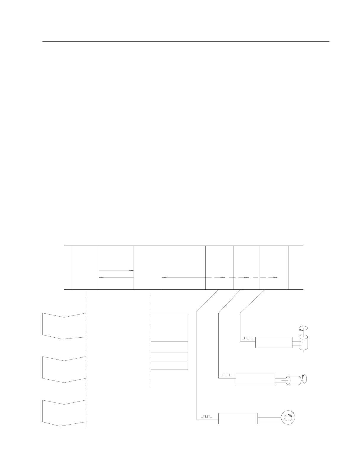
Figure 1.1
Typical System Block Diagram
1771 I/O Rack
1771–OJ 1771–OJ 1771–OJ
1771–M1
Stepper
Controller
Module
Backplane
Communications
Pulse
Output
Expander
#3
Pulse
Output
Expander
#2
Pulse
Output
Expander
#1
Move
Data
Axis #1
Move
Data
Axis #2
Move
Data
Axis #3
Status
Data
Axis #1
Axis #2
Axis #3
Translator
Translator
Translator
Axis #2
•
Axis #3
Publication 1771-UM002A–EN–P – May 2000
Stepper
Motor
Axis #1
Stepper
Motor
Stepper
Motor
10509
Page 8

1–2 Introduction
Stepper motor positioning assemblies can be used in applications
requiring more than three axes by using additional I/O chassis. The
stepper assemblies can be distributed throughout the plant using
remote I/O or data highway configurations.
Typically, each axis can control a linear slide although not limited to
that type of mechanical load. The axes can be controlled
independently or control of the axes can be synchronized.
Programming is based on a data block format where blocks of data
can be manipulated using block format instructions such as
file-to-file move and block transfer read and write instructions. The
stepper positioning assembly can be used with any Allen-Bradley
programmable controller that has block transfer capability and an
expandable data table except for Mini-PLC-2 (cat. no. 1772-LN3)
and PLC-2/20 (cat. no. 1772-LP1) Processors.
When using the PLC-2/20, programming will be more lengthy
because data must be transferred using repeated get/put (word)
transfer instructions.
Understand Compliance to
European Union Directives
The number of axes that can be controlled and the complexity of
motion will depend on the memory available for the positioning
program after the data table of the PC processor has been expanded
to store the data blocks.
If this product has the CE mark it is approved for installation within
the European Union and EEA regions. It has been designed and
tested to meet the following directives.
EMC Directive
This product is tested to meet Council Directive 89/336/EEC
Electromagnetic Compatibility (EMC) and the following standards,
in whole or in part, documented in a technical construction file:
• EN 50081-2EMC – Generic Emission Standard,
Part 2 – Industrial Environment
• EN 50082-2EMC – Generic Immunity Standard,
Part 2 – Industrial Environment
This product is intended for use in an industrial environment.
Publication 1771-UM002A–EN–P – May 2000
Low Voltage Directive
This product is tested to meet Council Directive 73/23/EEC
Low Voltage, by applying the safety requirements of EN 61131–2
Programmable Controllers, Part 2 – Equipment Requirements and
Tests.
Page 9

1–3Introduction
For specific information required by EN 61131-2, see the appropriate
sections in this publication, as well as “Industrial Automation Wiring
and Grounding Guidelines For Noise Immunity,” Allen-Bradley
publication 1770-4.1
Open style devices must be provided with environmental and safety
protection by proper mounting in enclosures designed for specific
application conditions. See NEMA Standards publication 250 and
IEC publication 529, as applicable, for explanations of the degrees of
protection provided by different types of enclosure.
Publication 1771-UM002A–EN–P – May 2000
Page 10

1–4 Introduction
Publication 1771-UM002A–EN–P – May 2000
Page 11
Chapter
Assembly and Installation
2
General
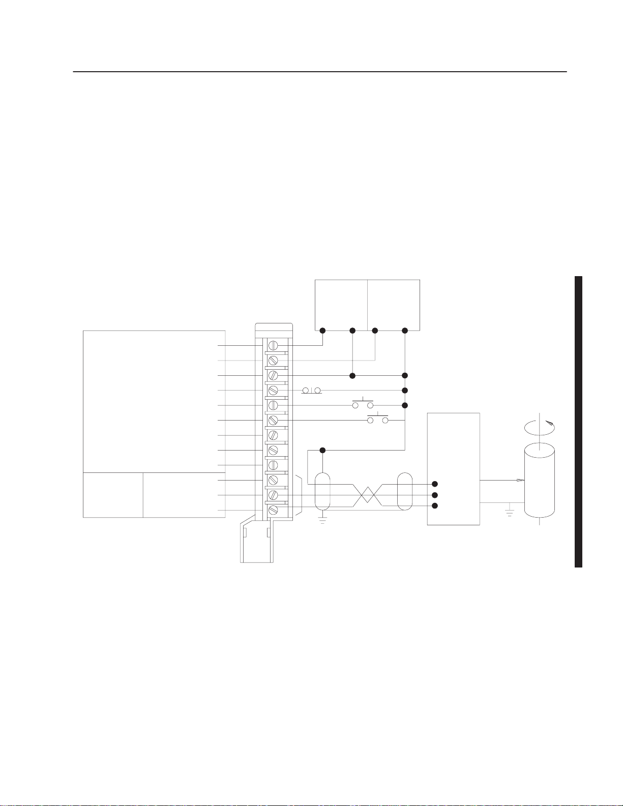
Rate
Fwd Dir
Rev Dir
+ DC Input Supply
+ DC Output Supply
Common
Stop Input
Jog Forward Input
Jog Reverse Input
Not Used
Not Used
Not Used
Not Used
Fwd Rate
Rev Rate
The stepper positioning assembly can be wired for 1-axis operation
with a stepper translator and motor as shown in Figure 2.1. One
stepper controller module can control up to three pulse output
expander modules installed in the same chassis. When the
application calls for 2-or 3-axis control, each additional expander
module should be wired as shown in Figure 2.1. No more than one
stepper controller module can operate in an I/O chassis.
Figure 2.1
Typical 1-Axis Connection Diagram
Pulse Output
Expander Module
Field Wiring Arm
1771–WB
1
2
3
4
5
6
7
8
9
10
11
12
Input
NEC Class 2
Power
Supply
+–+–
Rate Pulses/
Directional Signals
Output
NEC Class 2
Power
Supply
Stepper
Translator
and
Power
Supply
Mechanical
Load
Stepper
Motor
10510
Input Considerations
Pulse output expander modules can be controlled manually by the
use of switch inputs for stop, jog forward and jog reverse. The stop
switch will cause output pulses to the corresponding axis to cease
instantaneously. Jog switches are operational only when the
corresponding axis is at rest.
Publication 1771-UM002A–EN–P – May 2000
Page 12

2–2 Assembly and Installation
Input switch contacts should be compatible with the voltage and
current levels of the input circuits. The pulse output expander
module will accept inputs from open collector logic devices or
grounded switch contacts, and inputs from the Allen-Bradley
Encoder/Counter Module (cat. no. 1771-IJ, -IK). Refer to section
titled “Module Specifications” for additional input specifications.
Power Supply
Considerations
Each module in the I/O chassis including the processor or adapter
module draws power from the I/O (chassis) power supply. Some
modules require an additional power source.
I/O Power Supply
Power is supplied through the I/O chassis backplane from the 5V DC
I/O power supply. The stepper controller draws all of its power
(1.75A, maximum) from the I/O power supply. Each pulse output
expander module requires a current of 0.80A maximum. These
amounts (4.15A maximum for a 3-axis system) should be totalled
with the current requirements of all other modules in the chassis so
as not to exceed the maximum output current of the I/O chassis
power supply.
Auxiliary Power Supply
Pulse output expander modules require an additional power source
for switch inputs to the module and for pulse outputs to the stepper
translator and motor. The power source can be separate input and
output power supplies for one, two or three axes, a combined power
source for each axis, or a combined power source for up to three
axes. The power supply must be NEC Class 2 listed. Each input
switch draws 11mA maximum when closed. The maximum output
current for the pulse output expander module is 100mA. Refer to
Appendix A, Module Specifications” for additional information
concerning the auxiliary power supply requirements.
Publication 1771-UM002A–EN–P – May 2000
The supply voltage can be any value chosen from 5V DC to 30V DC
required by the user-selected stepper translator and/or the switch
input circuits. The variation in the DC voltage level due to ripple
should not exceed the input specification for the stepper translator
because the supply voltage ripple appears at the output terminals of
the pulse output expander module. Power supplies with 15mV
peak-to-peak ripple can be used. However, check the translator input
specification to ensure that the power supply specifications meet
translator input requirements. The supply may require input filtering
to guard against electrical noise.
Page 13

2–3Assembly and Installation
Stepper Translator and Power Supply
The stepper translator and power supply convert digital information
from the pulse output expander module into the proper voltage and
current for the precise control of a stepper motor. For compatibility
with the pulse output expander module, the translator must accept
low true logic. The programmed maximum pulse rate from the pulse
output expander module to the translator can be any value up to
20,000 pulses per second.
Stepper Motor
The stepper motor converts electrical pulses into mechanical
movements. The motor shaft rotates through a specific angular
rotation for each pulse. The movement is repeated precisely with
each pulse and the shaft rotates in fixed, repeatable increments.
When a threaded shaft is used to drive a linear slide, the velocity,
distance and direction of the slide can be precisely controlled.
Pulse Output Expander
Module
The stepper motor, stepper translator and translator power supply
should be grounded to guard against electrical noise interference in
accordance with the manufacturer’s specifications and guidelines.
Improper grounding can result in unwanted extra pulses occurring at
the stepper translator and/or stepper motor.
Prior to installation, a pulse output expander module must be
configured to correctly interface with the corresponding stepper
translator.
Adjustments are made using six switch assemblies. The functions of
the switches are summarized in Table 2.A and described in
subsequent paragraphs.
Module Disassembly
The switch assemblies are located on the module printed circuit
board. They are accessed as follows:
1. Remove the four screws from the upper and lower edges of the
labeled cover.
2. Remove the printed circuit board from the covers and set it
solder-side down.
3. Locate the switch assemblies labeled S1 through S6 as shown in
Figure 2.2.
Publication 1771-UM002A–EN–P – May 2000
Page 14
2–4 Assembly and Installation
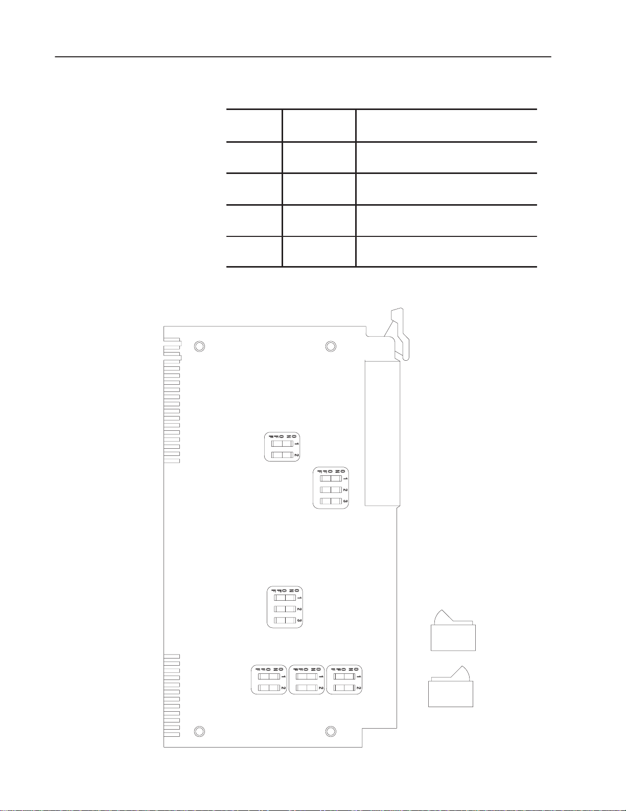
Table 2.A
Summary of Internal Switch Functions
Switch
Assembly Function Description
1 Output Format Separate forward and reverse pulse outputs,
or Pulse out, direction output
2 Input Logic low = true or
high = true
3 Expander Module
Address
Each expander module must have a different
binary address, either 1, 2 ,or 3.
4, 5, 6 Module Output Push-Pull or Current Source (open emitter), or
Current Sink (open collector).
Figure 2.2
Location of Dip Switch Assemblies
S1
S2
Publication 1771-UM002A–EN–P – May 2000
S3
S4 S5 S6
OFF
OFF
OFF
ON
ON
ON
10511
Page 15

2–5Assembly and Installation
4. Set the switches as described in the following sections. Some
switches are labeled on/off. Others may be labeled open for the
off position.
5. Reassemble the module. Start all four screws before tightening to
facilitate alignment of the covers and printed circuit board.
Output Format (S1)
The output format that determines forward or reverse motion differs
between translators. Therefore, the output terminals of the pulse
expander module are user-selectable to match the required pulse
input configuration of the translator. There are two basic translator
input configurations.
Some translators are designed to receive a pulse train at either one of
two terminals, depending on the direction of rotation desired in the
stepping motor. With this type of translator, a pulse train sent from
the pulse output expander module to one of the translator terminals
causes the stepping motor to rotate in the forward direction. An
identical pulse train sent from the module to the other translator
terminal causes the stepping motor to rotate in the reverse direction.
Output terminals on the pulse output expander module can be
selected in accordance with Table 2.B.
Table 2.B
Output Format (S1)
Switch Assembly S1
Switch 1 Switch 2
either ON
or OFF
OFF ON 10
ON ON 10
Note: Low = true logic
OFF 10
Output
Terminal
11
12
11
12
11
12
Active Output
Configurations &
Logic Levels
High
Forward Pulse train
Reverse Pulse train
Pulse train
Low High
(Forward) (Reverse)
High Low
Pulse train
Low High
(Forward) (Reverse)
High Low
Logic
Level
When
Stopped
High
High
High
High
Last State
Last State
High
High
High
Publication 1771-UM002A–EN–P – May 2000
Page 16

2–6 Assembly and Installation
Other translators are designed to receive only one pulse train at a
single “pulse” terminal. These translators usually have a separate
terminal for direction information. If a high (or low) signal is sent to
the “direction” terminal, the stepping motor rotates in the reverse
direction. If a low (or high) signal is sent to this terminal, the
stepping motor rotates in the forward direction. The rate of rotation
(in either direction) is controlled by the pulse train at the “pulse”
terminal.
The status of the pulse output expander module’s outputs when
motion has stopped is also user-selectable.
The settings of switch assembly S1 for the output format are
summarized in Table 2.B.
Input Logic (S2)
The choice of low true or high true logic for manual control of the
pulse output expander module’s hardware inputs is user-selectable.
The S2 switch assembly settings are summarized in Table 2.C.
Table 2.C
Input Logic (S2)
Switch
Number Motion Control Input Logic
1 STOP OFF = High true
ON = Low true
2 JOG
FORWARD
3 JOG
REVERSE
OFF = High true
ON = Low true
OFF = High true
ON = Low true
Expander Module Address (S3)
Each pulse output expander module must have its own (binary)
address for communication with the stepper controller module.
Allowable addresses are 1 (001), 2 (010) or 3 (011). They can be set
using switches 1 and 2. Switch 3 is always off. No other
combinations of the S3 switch assembly settings are valid. Refer to
Table 2.D.
Publication 1771-UM002A–EN–P – May 2000
Page 17
2–7Assembly and Installation
Table 2.D
Expander Module Address (S3)
Switch Assembly S3 Expander
Switch 1 Switch 2 Switch 3 Address
ON OFF OFF 1
OFF ON OFF 2
ON ON OFF 3
Expander Module Output (S4, S5, S6)
The choice of pulse output expander module output, either push-pull,
current source (open emitter) or current sink (open collector), is
user-selectable to best match the input characteristics of the stepper
translator.
PUSH-PULL-OPEN The push-pull output is compatible with many
stepper translators. The expander module output is wired to the
translator input as shown in Figure 2.1.
3
10
11
12
Expander Module
Common
Direction
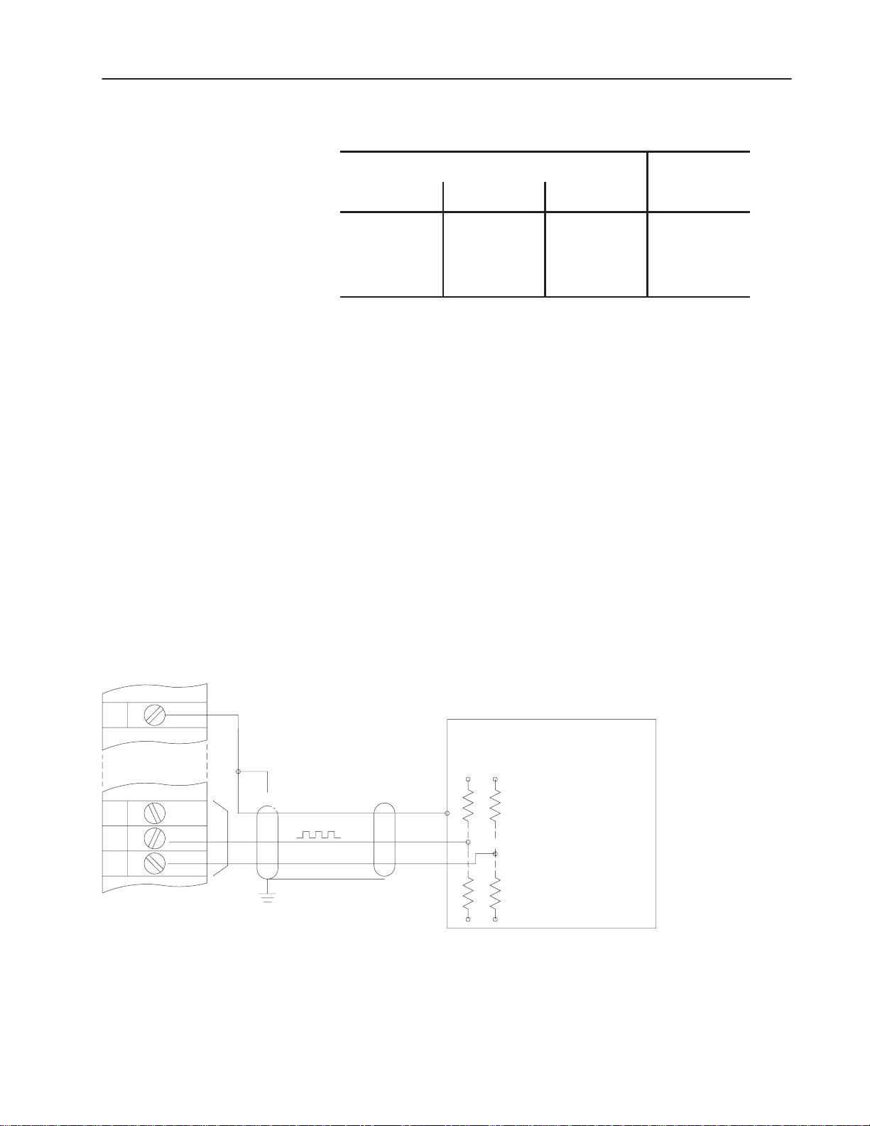
CURRENT SOURCE or CURRENT SINK-OPEN When using the
expander module as a current source or sink for the output pulses, it
may be necessary to use a pull-down or pull-up resistor, respectively
(Figure 2.3) Refer to the translator input specifications and
installation instructions for correct use of this resistor if it is required.
Figure 2.3
Output Source or Sink Connections
+Supply
Pull–Up
Resistors
(Current Sink)
or
Pull–Down
Resistors
(Current Source)
–Supply
Translator
10512
The positive (+) and negative (-) terminals of the output power
supply must be connected to the + DC OUTPUT SUPPLY and
COMMON terminals, respectively, of the module field wiring arm
regardless of the choice of module output.
Publication 1771-UM002A–EN–P – May 2000
Page 18
2–8 Assembly and Installation
ATTENTION: Avoid shorting any of the output
terminals to ground, to the common terminal, or to the
!
positive (+) terminal of a power supply. Damage to the
module could occur.
The settings of switch assemblies S4, S5 and S6 for the desired
module output are summarized in Table 2.E.
Set all switch positions in assemblies S4, S5 and S6 to the same
output configuration.
Table 2.E
Expander Module Output (S4, S5, S6)
Diagnostic Indicators
Switch
Assembly
S6
S5
S4 ON
Set all switch positions in assemblies S6, S5, and S4 to the same output configuration.
Switch 1Switch2Output
ON
OFF
ON
ON
OFF
ON
OFF
ON
OFF
ON
ON
OFF
ON
ON
OFF
ON
ON
Terminal Module Output
10
11
12 Current Source (Open Emitter)
Current Source (Open Emitter)
Current Sink (Open Collector)
Push-Pull
Current Source (Open Emitter)
Current Sink (Open Collector)
Push-Pull
Current Sink (Open Collector)
Push-Pull
The stepper controller and pulse output expander modules have LED
indicators. Their color and function are described in the following
paragraphs.
Stepper Controller Indicators
Publication 1771-UM002A–EN–P – May 2000
Three LED indicators are located on the upper front panel of the
stepper controller module. They perform the following functions.
• PC COMMUNICATIONS FAULT (Red)
This indicator is normally off. If a communications fault between
the stepper controller module and the PC processor is detected, or
a stepper controller module hardware fault is detected, this
indicator will illuminate.
Page 19

• EXPANDER COMMUNICATIONS FAULT (Red)
This indicator is normally off. If a communications fault between
the stepper controller module and any one of the pulse output
expander modules is detected, or a hardware fault in any one of
the pulse output expander modules is detected, this indicator will
illuminate.
Important: If both red indicators illuminate simultaneously at
power-up, the stepper controller module has a hardware
fault.
• ACTIVE (Green)
This indicator illuminates unless a hardware fault on the stepper
controller module is detected causing it to turn off. At power-up
this LED will not illuminate until the PC processor is in run
mode. This indicator will flash on/off if, after power-up, an
invalid expander address is detected, no expander module is
present and/or another stepper controller module is detected in the
same I/O rack.
2–9Assembly and Installation
Expander Module Indicators
Five LED indicators are located on the upper front panel of the pulse
output expander module (Figure 2.4). They perform the following
functions:
• MODULE FAULT (Red)
This LED is normally off. If an expander module hardware fault
is detected, it will illuminate.
• OUTPUT PULSE RATE (Green)
This LED is normally on or flashing at the output pulse rate
whenever an output is present.
• STOP INPUT (Orange)
This LED illuminates when a hardware stop input is asserted.
• JOG FORWARD (Orange)
This LED illuminates when a hardware jog forward input is
asserted.
• JOG REVERSE (Orange)
This LED illuminates when a hardware jog reverse input is
asserted.
Installation
The stepper positioning system is susceptible to electrical noise
unless the equipment is properly grounded, the cabling is properly
shielded and the power supply(ies) is properly filtered. If not, an
incorrect number of position pulses could result.
Publication 1771-UM002A–EN–P – May 2000
Page 20

2–10 Assembly and Installation
System Grounding Considerations
The following should be connected to earth ground:
• Ground prong of all AC line cords
• Negative (-) or common terminal of the I/O power supply(ies)
• One I/O chassis mounting stud
Ground the drain wire of the cable connecting the pulse output
expander module to the stepper translator. This cable should be
grounded either at the translator or at the I/O chassis, but not both.
See Shield Connection below.
The stepper translator, power supply and motor should be grounded
in accordance with the manufacturer’s instructions.
ATTENTION: Improper system grounding can result
in additional unwanted pulses occurring at the stepper
!
translator and/or stepper motor. Unpredictable
machine motion could occur with possible damage to
equipment and/or injury to personnel.
Cable Considerations
The stepper translator should be wired to the field wiring arm using a
twisted 3-conductor shielded cable (Belden 8771). The cable
distance between the pulse output expander module and the stepper
translator generally should not exceed 40 feet.
Shield Connection
Belden 8771 cable has a foil shield with a bare drain wire. The
shield should be connected to earth ground at one end of the cable
only. This can be at the customer end of the cable or at an I/O
chassis mounting bolt or stud. At the other end of the cable, the
shield should be cut short, bent back and taped to insulate it from any
electrical contact. This practice helps to guard against unwanted
radiated electrical noise and ground current loops.
Module Keying
Plastic keying bands shipped with each I/O chassis provide an easy
method for keying an I/O slot to accept only one type of module. Use
of the keying bands is strongly recommended.
Publication 1771-UM002A–EN–P – May 2000
Page 21
2–11Assembly and Installation
The module is slotted in two places on its rear edge. The position of
the keying bands on the backplane connector must correspond to the
slots to allow insertion of the module so that only the desired module
will fit in this slot.
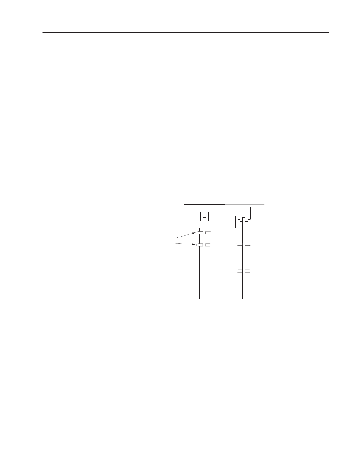
Refer to Figure 2.4. Snap the keying bands on the upper backplane
connectors between these numbers printed on the backplane:
Stepper Controller
2 and 4
8 and 10
Expander Module
8 and 10
22 and 24
Needle-noise pliers can be used to insert or remove keying bands.
Figure 2.4
Keying Diagram
Stepper Expander
Controller Module(s)
Keying
Bands
2
4
6
8
10
12
14
16
18
20
22
24
26
28
30
32
34
36
2
4
6
8
10
12
14
16
18
20
22
24
26
28
30
32
34
36
10513
Compatibility
An I/O chassis that contains a stepper controller module may not
contain another “master” intelligent I/O module.
Module Specifications
The pulse output expander module specifications and stepper
controller module specifications are listed in Appendix A.
Publication 1771-UM002A–EN–P – May 2000
Page 22

2–12 Assembly and Installation
Publication 1771-UM002A–EN–P – May 2000
Page 23

Chapter
Programming and Operation
3
General
The desired motion of the stepper motor can be accelerated,
decelerated or maintained at constant rate by controlling the pulse
rate from the pulse output expander module. Motion can be
rotational such as used to position an indexing table, or can be linear
such as obtained when a linear slide is driven forward or backward
by turning a threaded shaft. In either case, the position at any given
moment is defined by the number of pulses sent to the stepper motor.
It can result in some number of degrees of rotation or linear units of
travel.
The motion can be programmed by manipulating data table words
(control blocks) arranged in a convenient format. Blocks of data are
also used to indicate that commands were received and desired
motion was implemented (status block). Control and status blocks
are communicated bidirectionally between the PC processor and
stepper controller module by block transfer programming.
The task of programming requires that control and status block be
assigned in the data table and that control data be entered using the
industrial terminal. Control blocks sent to the stepper controller
module by write block transfers govern acceleration, deceleration,
final rate and final position. Control blocks also contain control
words. Bits in control words must be set according to the particular
application and desired motion.
Positioning Concepts
The stepper controller module sends status blocks of data to the PC
processor using read block transfers. Status blocks contain current
position information and diagnostic bits set by the stepper
positioning assembly.
The format of the data blocks and the function of status and control
bits will be covered later in this chapter.
There are three stepper positioning concepts which should be
understood before learning how the stepper positioning assembly is
programmed. They are:
• Move Definition
• Moveset
• Positioning Modes
Publication 1771-UM002A–EN–P – May 2000
Page 24
3–2 Programming and Operation
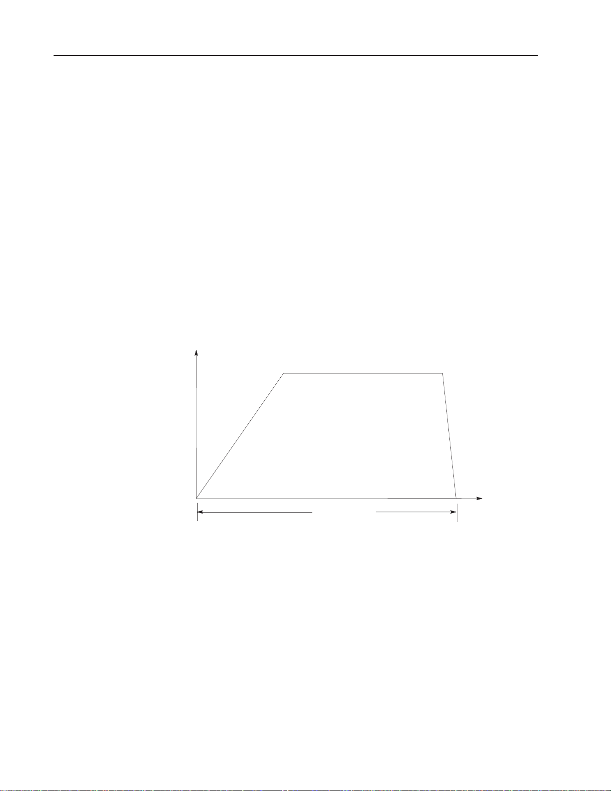
Move Definition
A move in its simplest form consists of an acceleration of the stepper
motor axis, a final rate, a deceleration to zero and a final position
(Figure 3.1). The value for an acceleration is the time required to
achieve a final rate. Values can be chosen from 0-9.99 seconds. The
final rate determines the constant speed of machine motion. The
final rate value can vary from 1 to 20,000 pulses per second. The
decel value, any value from 0-9.99 seconds, is the time required to
decelerate to zero pulses per second from a final rate.
The final position of a move is the number of pulses between 0 and
999,999 to be achieved by the move. The physical location will
depend on the resolution (pulses per degree of rotation or pulses per
inch of travel, etc.) of the stepper translator/motor configuration and
the specific application (gearing threads per inch of the linear axis,
etc.).
Figure 3.1
Move Definition
Rate
Ramp (Accel)
(0-9.99 Sec)
Final Rate
(1–20,000 Pulse/Sec)
Decel
(0-9.99 Sec)
Final Position
0–999,999 Pulses
Position
10514
Moveset
A moveset refers to the data used to control from 1 to 10 moves.
Sequential moves can be blended to form a continuous move profile
or can be implemented one move at a time where motion stops
between moves. A moveset can be executed using a minimum of
ladder diagram programming.
Publication 1771-UM002A–EN–P – May 2000
Two or more movesets can be implemented sequentially as if they
were a single large moveset. The stepper positioning assembly can
store two movesets simultaneously for up to three axes. When one
moveset is in operation (working moveset), the next moveset is in
storage (storage moveset). In the continuous mode, the last move of
the working moveset is blended with the first move of the storage
moveset.
Page 25
3–3Programming and Operation
In any mode, when the working moveset is finished, the storage
moveset automatically becomes the next working moveset. Then
another (storage) moveset can be block transferred to the stepper
positioning assembly.
In the continuous and independent modes of operation, the storage
moveset must be received by the stepper controller module before
the third from last move of the working moveset is complete (for
example, move 8 of 10 moves). In the single-step mode, the storage
moveset must be received before the second from last move of the
working moveset is completed. Skipped moves (section titled
“Move Block,” Bit 02) are not counted. The use of multiple
movesets allows long and complex positioning profiles or long
sequences of single moves to be performed with little additional
programming. The moveset is further defined in section titled
“Moveset Block.”
Positioning Modes
The stepper positioning assembly can be programmed for operation
that is tailored to the application requirements. The positioning
modes determine the type of positioning profile and the manner in
which the axes of two or three stepper motors can be coordinated.
The stepper positioning assembly can also be operated manually
using hardware or software jog inputs.
Single-Step Mode
In the single-step mode, a moveset allows the individual moves to be
controlled one at a time. A start command from the PC processor
starts the first move of the sequence. After the move is completed,
the stepper motor axis stops and a done bit is set. In order for the
next move to begin, the PC processor must transfer another start
command to the stepper controller module (Figure 3.2).
Figure 3.2
Single Step Mode
Rate
Final
Rate
Start
Command
Final
Rate
Ramp
Decel
Ramp
Move 1 Move 2 Move 3
Final
Position
Start
Command
Decel
Final
Position
Ramp
Final
Rate
Start
Command
Decel
Time
Final
Position
Done Bit
is set
Note: Jogging between moves causes a system fault..
Done Bit
is set
Publication 1771-UM002A–EN–P – May 2000
Done Bit
is set
10515
Page 26

3–4 Programming and Operation
Jog
A jog allows an axis to be manually controlled by an operator
independent of other axes in the system. This can be done at any
time except when a positioning profile is in progress. A jog can be
initiated by a hardware or software input to the stepper positioning
assembly.
Jog data is one move block that controls one axis. The job move
block typically is contained in a separate 1-move (10-word) moveset.
The jog move block can also be contained in a moveset with other
moves. If so, the jog must be the first move of the moveset. The
remaining moves will be ignored as a result of the stepper controller
module processing the jog move block. After the jog has been
executed as needed, the remaining moves can be initiated by again
transferring the same moveset to the stepper controller module. This
time a skip bit must be set in the jog data and the jog load bit must be
cleared. (These bits are described in section titled “Move Block,”
Bit 02 and 03). The positioning profile will then start with move two
and ignore the jog data.
The jog can be initiated by jog forward or jog reverse user-supplied
input switches or by ladder diagram logic. An axis must be at rest
before a jog can be initiated. As long as the jog input is asserted, the
jog will continue at the specified rate.
Once released (off) the jog will decelerate to a zero rate over the time
defined by the decel value programmed in the jog move. If desired,
the final position value can serve as an upper (or lower) limit of jog
travel. The jog will automatically decelerate to reach a zero rate at
the programmed final position if the jog input is held on.
If the final position value of the jog is programmed as zero, the limit
of travel will be 999,999 pulses. If the decel value is programmed as
zero, the jog rate will cease instantly when the jog input is turned off.
ATTENTION: Avoid damage to the stepper motor
and machine by selecting jog final rate and decel
!
values which are compatible with the stepper
motor/machine dynamics.
Publication 1771-UM002A–EN–P – May 2000
Page 27
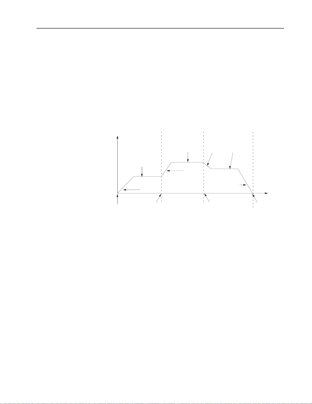
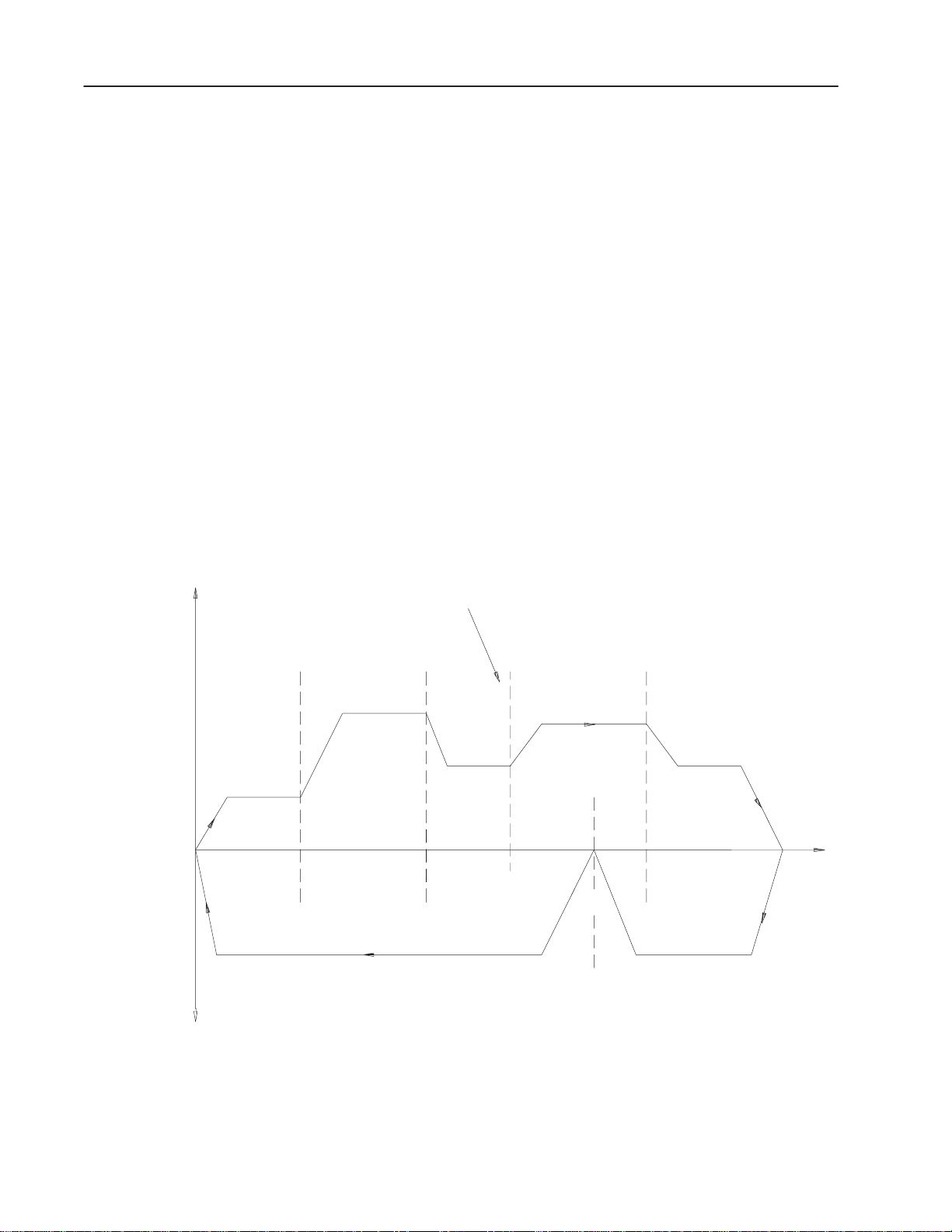
Continuous Mode
The continuous mode allows moves of the moveset to be blended
continuously into a move profile with fully programmed
accelerations and decelerations. One start command is required for
the entire positioning profile. A done bit is set at completion. Each
move is defined as having a ramp, a final rate and a final position.
The last move of the profile, in addition to the ramp, final rate and
final position, contains a deceleration to zero (Figure 3.3). The decel
value does not affect the positioning profile in any move except the
last move.
Figure 3.3
Continuous Mode
Rate
3–5Programming and Operation
Final
Rate 3
Decel 3
Done Bit
is set
Start
Command
Final
Rate 2
Final
Rate 1
Ramp 2
Ramp 1
Move 1 Move 2 Move 3
Final
Position 1
Ramp 3
Final
Position 2
Synchronization of Axes
All axes (up to three) can be synchronized move-by-move in the
single-step and independent modes. Each axis must complete a
given move before any axis is allowed to begin the next move.
Coordination is independent of PC processor scan time. If two axes
are synchronized, then the third axis, if used, must also be
synchronized. Synchronized axes must operate in the same
positioning mode.
Position
Final
Position 3
10515
A start command can be programmed for only one of the
synchronized axes. In the single-step positioning mode, this must be
done for each move of the moveset. Start commands received during
a move will be ignored. Done bits for all axes must be set before a
start command is executed. In the continuous and independent
modes, one start command is required at the beginning of the
synchronized profiles.
Publication 1771-UM002A–EN–P – May 2000
Page 28
3–6 Programming and Operation
A done bit is set for each axis at completion of each positioning
profile. If all axes (up to three) are not synchronized, then the
control of any axis is completely independent of the other(s). Three
different single-axis machines could be controlled by one stepper
controller module and three pulse output expander modules in one
I/O chassis.
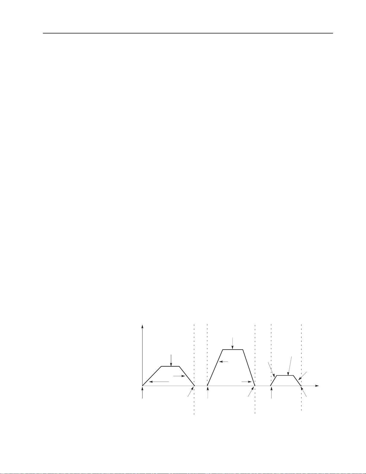
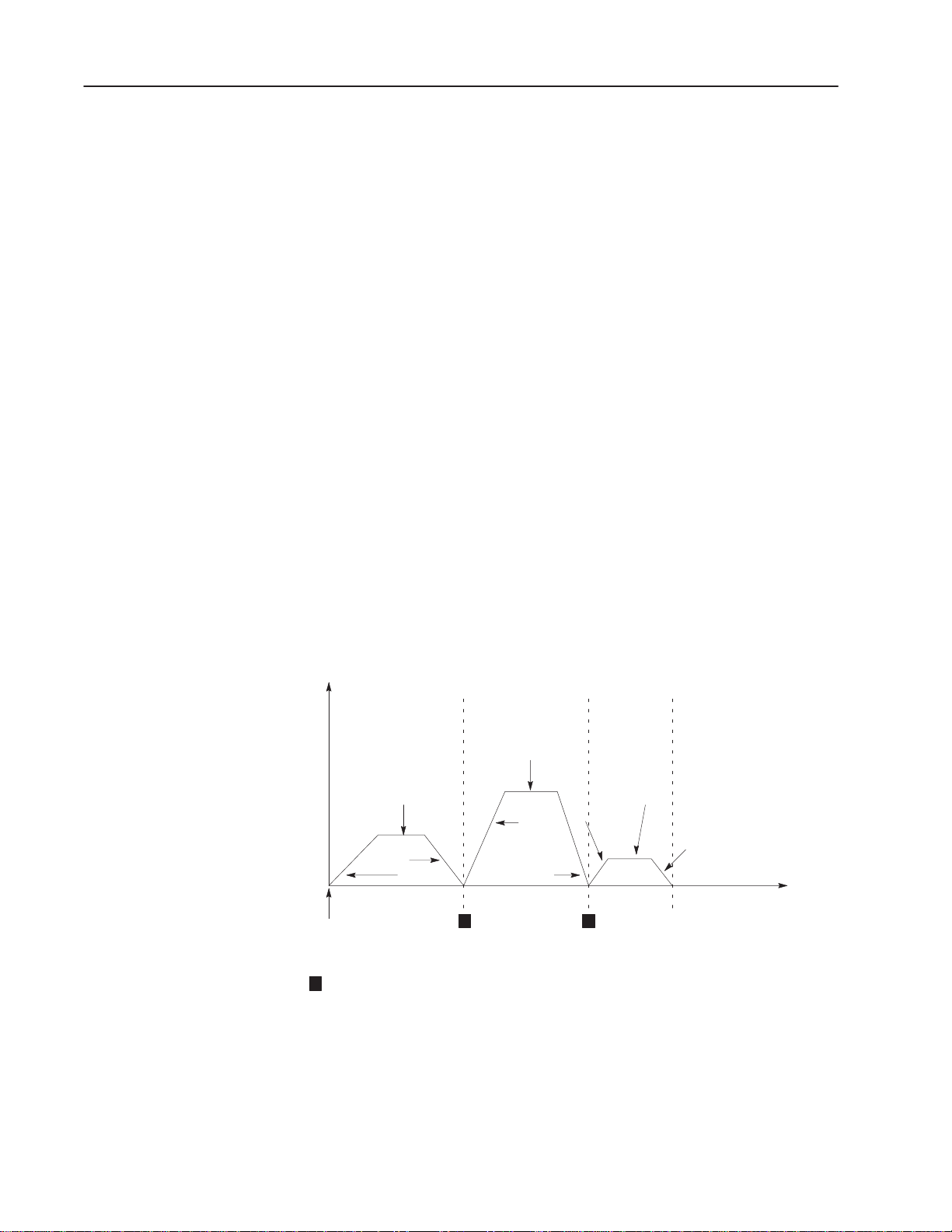
Independent Mode
The independent mode allows a chain of single-step moves to be
sequentially executed. Each move is defined as having a ramp, final
rate, decel (to 0Hz rate) and a final position. Typically there is a
pause of 10-30ms from the end of one move to the beginning of the
next (dwell at 0Hz rate). Refer to Figure 3.4. One start command is
required for the entire positioning profile. A done bit is set at the
completion of each move.
Important: Done bits which are set between moves in the
independent mode should not be used because they
remain set for too short a time. Only the done bit of the
last move should be examined. This can be achieved by
examining the number that identifies the last move
(status bit 10-13) and the done bit in the same rung.
Figure 3.4
Independent Mode
Rate
Final
Rate
Final
Rate
Ramp
Decel
Ramp
Move 1 Move 2 Move 3
Start
Command
1
The done bit remains set until the start of the next move (10msec dwell time, nominal)
1
Decel
Ramp
1
Final
Rate
Decel
Done Bit
is set
Position
10517
Publication 1771-UM002A–EN–P – May 2000
Page 29
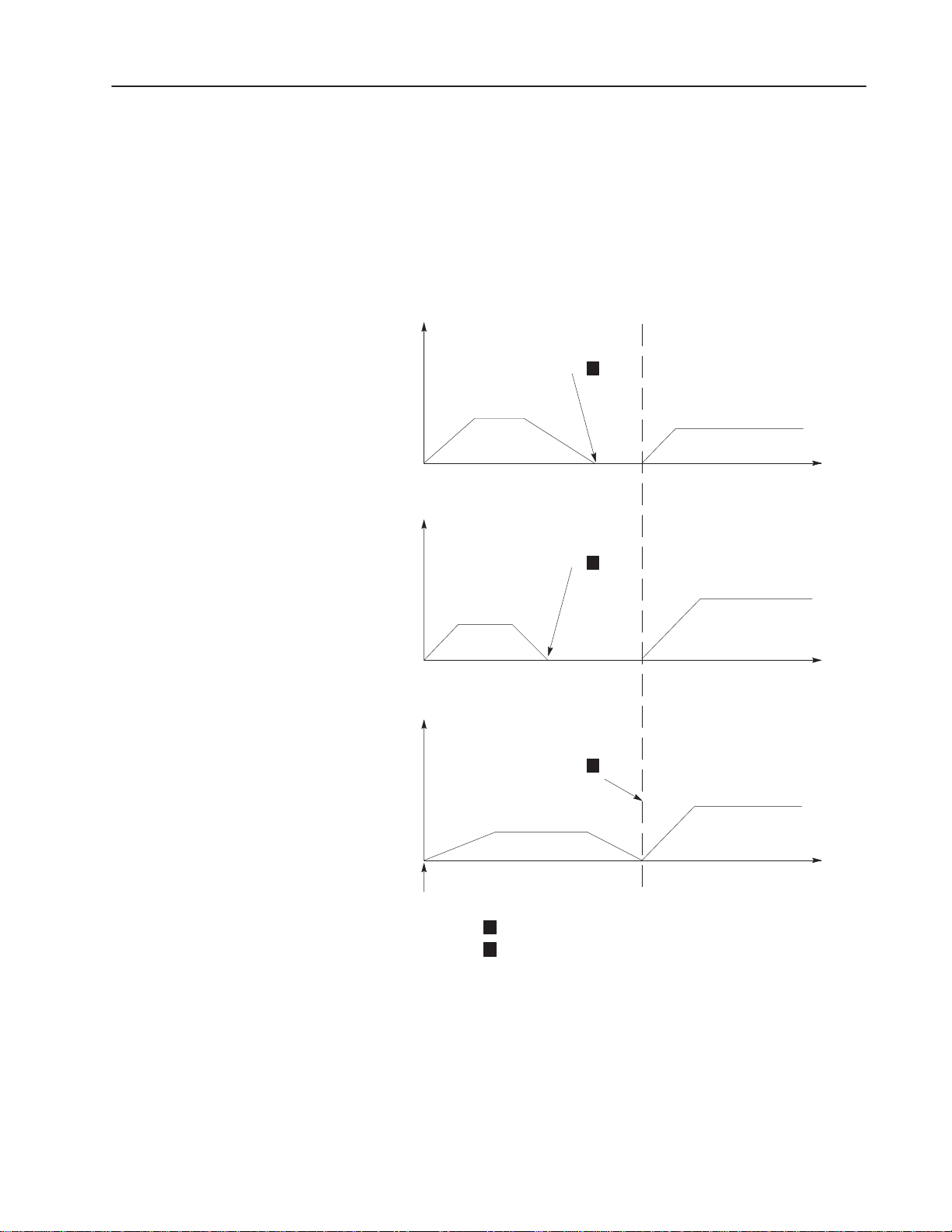
When using the independent mode and the axes are synchronized, all
but the last axis to finish the move in process will stop motion when
finished and wait for the last axis to complete its move. All axes will
then begin the next move simultaneously as soon as the last axis has
finished its move. The process then repeats for each move in the
positioning profile (Figure 3.5).
Figure 3.5
Synchronized Axes (Independent Mode)
Rate
Done Bit
is set
Expander
# 1
1
3–7Programming and Operation
Expander
# 2
Expander
# 3
Rate
Rate
Start
Command
Move 1 Move 2
Done Bit
is set
1
Move 1 Move 2
Done Bit
is set
2
Move 1 Move 2
1
Done bit remains set until start of next move.
Done bit dwell time, 10msec, nominal.
2
Time
Time
Time
10518
Publication 1771-UM002A–EN–P – May 2000
Page 30
3–8 Programming and Operation
Data Block Concepts
Words that control the motion of the stepper motor axis, record
position or monitor move diagnostics are stored in data table files.
These words are grouped into the following three kinds of data
blocks.
• Moveset Block
• Move Block
• Status Block
In addition to move data, the blocks contain special control or status
words. The bits in these words affect how the motion is controlled
or verify that the move commands and the move data were received
and implemented.
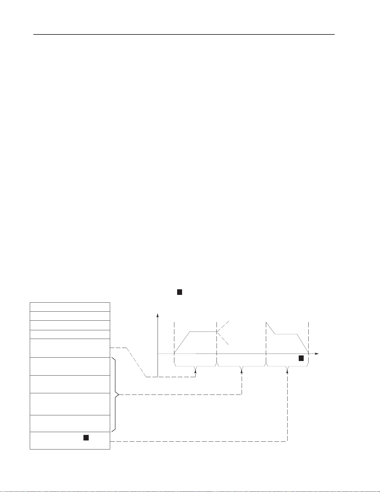
Moveset Block
The moveset block is a data table file for storing data and controlling
the motion of one stepper motor axis. It allows move data to be
stored in consecutive data table words to control up to 10 moves of a
positioning profile. Each axis must have at least one moveset block.
A moveset block must contain the following move data (Figure 3.6).
64–Word Moveset Block in
Data Table
Moveset Control Word
Offset word
MS Preset Word
LS Preset Word
Move Block # 1
Move Block # 2
Move Block # 3
• Moveset Control Word
• Offset and Preset Words
• One or more Moves
Figure 3.6
Moveset Block and Positioning Profile
1
The 64-word moveset block may
contain from 1 to 10 move blocks. If using less than
Rate
10 move blocks, fill all unused words with zeros or
a programming error results.
Move # 1 Interim Moves Move # 10
1
Position
Move Block # 9
Move Block # 10
Publication 1771-UM002A–EN–P – May 2000
1
10519
Page 31

3–9Programming and Operation
Moveset Control Word
A moveset block must contain a moveset control word as the first
word in the block. Each of the bits of the moveset control word
serves a function in the control of a stepper motor axis. Bit functions
of the moveset control word are defined below and summarized in
Figure 3.7.
Figure 3.7
Moveset Control Word
MCW
17 16 15 14 13 12 11 10 07 06 05 04 03 02 01 00
Override
Moveset
Jog Forward
Jog Reverse
Offset
Not Used (Must be zero)
Axis Address
Axis Address
2
Axis Addr.
1
2
3
Start
Profile Mode Select
Profile Mode Select
Synchronized Axes
Reset
Global/Axis
2
2
Bit 11
0
1
1
Bit 10 Mode
1
0
1
1
Continuous
Independent
Single Step
Bit 02
0
1
N/A
Stop
Decel/Instantaneous
Bit 01
0
0
1
Bit 00 Start Command Bit.
When this bit is set, the stepper controller module will start to
execute the first move of a continuous or independent mode
sequence or the next single step move.
Bit 01, 02 Mode Select Bits.
These two bits are used to determine the type of positioning profile.
Bit 01=0, Bit 02=0: Continuous Mode (Figure 3.3)
Bit 01=0, Bit 02=1: Independent Mode (Figure 3.4)
Bit 01=1, Bit 02=1 or 0: Single-Step Mode (Figure 3.2)
1
1
10520
Refer to section titled “Positioning Modes” for mode descriptions.
Publication 1771-UM002A–EN–P – May 2000
Page 32

3–10 Programming and Operation
Bit 03 Synchronized Axes Bit.
If this bit is set for any axis, it must be set for the other axes so that
all (two or three) axes controlled by the stepper positioning assembly
are synchronized. Synchronized axes must be operating in the same
positioning mode. (Bits 01, 02, and 03 must be set identically in the
moveset control words of the synchronized axes.) Refer to
“Synchronization of Axes.”
Bit 04 Reset Command Bit.
A reset command can be limited to a single axis or can reset all axes
(up to three) depending on the logic state of the global/axis bit (bit
05). With the exception of the done bit and reset bit, all status and
position information and all moveset data are cleared in the stepper
controller module when the reset command bit is set. The reset bit
and done bit are reset in the status word at the start of the first move
in the next moveset. The user program should clear the reset bit after
the reset has been executed as indicated by reset bit 05 in the status
word. Refer to section titled “Status Block.”
Bit 05 Global/Axis
Bit (for stop or reset commands, only).
When this bit is set, all axes controlled by the stepper positioning
assembly are stopped or reset with one command. (The
notation
refers to a low logic state.)
When this bit is zero, only the axis of the moveset defined by the
axis address bits (bits 10 and 11) is stopped or reset.
The function of this bit should be considered whenever the stop bit
(bit 06) or the reset bit (bit 04) is programmed.
Bit 06 Stop Command Bit.
When this bit is set, output pulses will cease either in a controlled
decel or instantly, depending on how the decel/instantaneous bit (bit
07) is set. A stop command can be limited to a single axis or can
apply to all axes (up to three) depending on how the global/axis (bit
05) is set.
All move profile data is cleared, but position and status information
remains the same in the stepper controller module when this bit is
set.
The user program should clear the stop bit after the stop command
has been executed as indicated by reset bit 05 in the status word.
Refer to section titled “Status Block.”
Publication 1771-UM002A–EN–P – May 2000
Bit 07 Decel/Instantaneous Bit.
When this bit is set, the output pulse rate will decelerate to zero in
accordance with the decel value in the move block that was being
executed when a software stop command was received.
Page 33

3–11Programming and Operation
When the decel/instantaneous bit is zero, output pulses will cease
instantly when a software stop command is received.
A hardware stop input in instantaneous, independent of the
decal/instantaneous bit.
This bit is generally set when a stop bit is set.
Bits 10, 11 Axis Address Bits.
These bits define the axis to be controlled by the data and/or
commands in the moveset block. The address in the moveset control
word of the moveset block must be identical to the settings of the
address switch assembly (S3) of the corresponding pulse output
expander module. The address bits of the moveset block are
generally set when the profile is initially programmed using the
industrial terminal. The setting of bits 11 and 10 respectively are 01
= axis 1, 10 = axis 2, 11 = axis 3.
Bit 12 Must always be zero.
Bit 13 Offset Command Bit.
When set, the value contained in the offset word (described below)
will be added to or subtracted from the final position value(s) of all
moves of the moveset blocks residing in the stepper controller
module memory. In all modes, the final position of each move is
shifted by the offset amount and direction.
Bit 17 of the offset word determines the direction of the shift, 1 for
subtracted or 0 for added.
Important: The present move being executed and the move
following may not be affected by the offset command in
all but the single step mode. In the single step mode,
only the present move will not be affected.
The user program should clear the offset bit and allow the stepper
controller module to see the bit cleared before another offset for that
axis is enabled.
Bit 14 Software Jog Reverse Command Bit.
The axis will move in the direction indicated for as long as this bit is
set or until the final position programmed in the jog move is reached.
Hardware jog inputs are disabled during this time. The jog will
follow the ramp, rate, decel and final position values programmed in
the jog move block.
In large systems or systems using remote I/O, the software jog
timing will depend on block transfer timing. Refer to section titled
“Handshaking.”
Publication 1771-UM002A–EN–P – May 2000
Page 34

3–12 Programming and Operation
The load jog command bit (bit 03 of the single move control word,
defined in section titled “Move Block”) must be set to identify jog
move block data.
The user program should clear the software jog reverse command bit
and allow the stepper controller module time to see the bit cleared
before another jog to that axis is enabled.
Bit 15 Software Jog Forward Command Bit.
Same as bit 14. See software jog reverse command bit.
Bit 16 Moveset Bit.
Successive movesets can be programmed for continuous execution
using the moveset bit. This bit can be used to label each block
transfer of move data as moveset 0 or moveset 1. When movesets
are alternately labeled 1 for the first, 0 for the second, 1 for the third,
etc., user program logic can sequence the movesets without
interruption as if they were one large moveset. The number of
successive movesets is limited only by processor memory.
Once a positioning profile has begun, none of the moves of the
working moveset can be updated. However, the storage moveset in
the stepper controller module can be updated provided that the
moveset bit in the transferred (updated) moveset has the same setting
(0 or 1) as the storage moveset bit. Refer to section titled
“Movesets.”
In large systems or systems using remote I/O, moveset timing will
depend upon block transfer timing. Refer to “Handshaking,” page
3–35, for more information.
Bit 17 Override Command Bit.
The override bit is set in the moveset containing the override data.
When the override command is enabled, the override bit causes the
current moveset to be interrupted and the override moveset to be
blended immediately. The first move of the override moveset is
blended with the interrupted move in progress. Refer to section
titled “Override Ramp Time Considerations” to ensure that the first
move of the override moveset will be compatible with any worst
case move in progress.
Generally, bits of the moveset control word are set by user program
logic. A command to the stepper controller module should be
cleared and the stepper controller module allowed sufficient time to
see the bit cleared before the next command is transferred. See the
section titled “Handshaking.”
Publication 1771-UM002A–EN–P – May 2000
Page 35

3–13Programming and Operation
Avoid sending multiple commands to the stepper controller module
at the same time. A programming error could result or the
data/command could be ignored.
All bits must be set carefully to tailor the move profile(s) to the
application requirements and to avoid illegal bit combinations. If
only one command is transferred at a time with proper handshaking,
no difficulty should be encountered. An illegal bit combination will
cause a programming error when data is received by the stepper
controller module or when move data is processed for execution.
Once the definitions of the bit functions have been learned, the table
of illegal bit combinations found in section titled “Illegal Bit
Combinations,” can be consulted as an aid in avoiding programming
errors when programming the required move profile(s).
Offset Word
The position offset allows an entire positioning profile (all moves of
the profile) to be shifted to compensate for machine wear without
reprogramming the profile (Figure 3.8). The offset value between 0
and 7,999 pulses, can be added to or subtracted from the final
position of each move in the moveset(s).
Rate
Figure 3.8
Offset
Offset
–+
0
Move 1
Move 2
–+
Move 3
–+
Position
10521
The offset value is entered in BCD in bits 00-16 of the offset word.
Bit 17 is the control bit that determines whether the offset will be
added to or subtracted from the final position (Figure 3.9). The
value entered in the figure is the maximum allowable value of offset.
Refer to offset command bit 13 of the moveset control word
described earlier in this section
Publication 1771-UM002A–EN–P – May 2000
Page 36

3–14 Programming and Operation
17 10 07 00
Figure 3.9
Offset and Preset Words
Data Table
MCW
0 = Add
1 = Subtract
1 = Assert
Initialization
Preset
0 = Move
Preset
0
0
0000
7
00
1
0
1
999
999
999
Offset
MS Preset
LS Preset
10522
The moves affected by the offset will be those stored in the working
and storage moveset when the command is received. If additional
movesets have been programmed, the offset command must be
re-enabled when additional movesets are transferred to the stepper
controller module.
Preset Word
The preset word can store values that serve two functions. One
function, initialization preset, is used by the stepper controller
module to define the starting point value of the positioning profile.
The other function, move preset, can be used to extend one or more
moves of the profile beyond the 999,999 pulse (position) limit of the
stepper controller module. In either case, the preset word can be
loaded with the necessary value, the function enabled and another
value loaded as needed. When used, the preset value becomes the
new position reference of the profile.
Publication 1771-UM002A–EN–P – May 2000
The preset can be any value between 0 and 999,999. Preset data is
contained in two words, one for the most significant (MS) 3 digits,
the other for the least significant (LS) 3 digits (Figure 3.9). Preset
values are entered in BCD in bits 00-13. Bits 14-17 in the LS preset
word and bits 14-16 in the MS preset word are undefined and must
be loaded with zeros. Bit 17 of the MS preset word is the assert bit
for the initialization preset.
Page 37

3–15Programming and Operation
Initialization Preset
Typically it may be necessary to jog the machine to a starting
position before the positioning profile(s) is (are) started. The
position register of the stepper controller module will read some
number of position pulses representing the machine starting position.
The initialization preset can be used to reset the value of the position
register to zero, or to any value that would be used as the profile
starting value.
If the preset value were not set equal to zero (or not equal to the
profile starting value), when started, the first move(s) of the profile
would be shortened or lengthened. The amount would be the
difference between the initialization preset and the starting point
value: shortened if the preset exceeded the starting point value or
lengthened if the value were less than the starting point value
(Figure 3.10).
ATTENTION: All moves must achieve a final rate
for a minimum duration of 20ms or a programming
!
error and a system fault will result. The minimum
duration of a move is covered in section titled
“Application Considerations.”
Rate
Figure 3.10
Initialization Preset and Starting Value
Preset > Starting Value
Preset = Starting Value
Preset < Starting Value
Initialization Preset
1
Final rate must be mainained for 20ms, minimum
Bit 17 of the MS preset word is the assert bit for the initialization
preset. When this bit is set, the preset value will be written over
whatever value is in the position register of the stepper controller
module. Once the positioning profile has been started, bit 17 must
not be set or a programming error will occur.
1
Position
Move 1
10523
Publication 1771-UM002A–EN–P – May 2000
Page 38
3–16 Programming and Operation
Move Preset
The move preset can be used to adjust the starting point value of any
move in a moveset whenever necessary. For example, the move
preset can extend one or more moves of the profile beyond the
999,999 pulse limit of the stepper controller module.
The move preset is enabled by bit 00 in the single move control word
(see section titled “Move Block”). When this bit is set, the position
register of the stepper controller module and the starting point value
of the move block will become the value stored in the preset words.
The final position value of the move block and all subsequent move
blocks will be referenced to this new starting point value.
If a move profile extends beyond 999,999 pulses and the application
calls for a return to the home position, it may be necessary to change
the preset value and again set the move preset bit (Figure 3.11).
When necessary, this must be done before the move to home position
is started. Reverse travel to the home position can require two
moves if the total travel exceeds 999,999 pulses.
Rate
Forward
Rate
Reverse
Figure 3.11
Move Preset
Move Preset
000,000
0
0
999k
Move Preset
999,999 (to return)
Position
10524
Publication 1771-UM002A–EN–P – May 2000
Page 39

3–17Programming and Operation
Move Block
A move block contains ramp, final rate, final position and
deceleration data that characterize a move. A moveset block must
contain from 1 to 10 move blocks. A move block contains the
following words (Figure 3.12):
• Single Move Control Word
• Move Data
Figure 3.12
Single Move Control Word
17 16 SMCW 03 02 01 00
110000000000
Always 1 to
identify the SMCW
Single Move Control Word
The single move control word is the first word in each move block.
The word contains two identification bits (bits 16, 17) and four bits
which affect the operation of the move (bits 00-03). The function of
each bit is defined below and summarized in Figure 3.12.
Bit 00 Move Preset Bit.
This bit, when set, causes the value contained in the preset words of
the moveset block to become the starting point value for that move.
The position register becomes this value. The preset value can be
changed and re-enabled as needed to further extend the position limit
or to allow the profile to return to the home position. Refer to
“Move Preset.”
Always Zero
Move Preset
Rate Multiplier
Move Skip
Load Jog
10526
Bit 01 Rate Multiplier Bit.
When the rate multiplier bit is set, final rates can be selected in 10
pulses per second increments between 0 and 20,000 pulses per
second.
When this bit is zero, any final rate from 1 to 9,999 pulses per
second can be selected in 1 pulse per second increments.
This bit would typically be set when ramp, rate and decel values are
initially set in the data table using the data monitor mode of the
industrial terminal.
Publication 1771-UM002A–EN–P – May 2000
Page 40

3–18 Programming and Operation
Bit 02 Skip Bit.
The skip bit allows one or more moves of a moveset to be ignored
without reprogramming. When this bit is set, the corresponding
move block is skipped over. When operating in the continuous
mode, the move preceding the skipped move and the move following
the skipped move are blended automatically. Refer to section titled
“Application Considerations” to ensure that the blend is achievable
without a programming error. When operating in the independent
mode, the move following the skipped move begins as soon as the
one preceding the skipped move is done. Skip bits can be set
initially in the data table when move data is entered or they can be
set by user program logic. Skip bits must be set before the moveset
is transferred to the stepper controller module. Once the moveset is
transferred, additional skip bits cannot be set in that moveset.
Bit 03 Load Jog Bit.
This bit is set to identify the accompanying move block as jog data.
Bit 14 software jog reverse command or bit 15 software jog forward
of the moveset control word can be programmed to initiate the jog.
Jog data (with the load jog bit set) can be transferred to the stepper
controller module with the software jog forward or reverse command
(bit 15 or 14), or jog data can be transferred to the stepper controller
module in advance. See software jog forward and reverse command
bits 15 and 14 of the moveset control word described earlier in this
section. Refer to the section titled “Jog.”
An axis reset command will clear any previously transferred jog data
for that axis.
Bit 04-15 Must always be zero.
Bit 16, 17 Identification Bits.
Both bits must be set to identify each single move control word.
Otherwise, a programming error will occur.
Generally, bits of the single move control word are set by user
program logic. A command to the stepper controller module should
be cleared and the stepper controller module allowed sufficient time
to see the bit cleared before the next command is transferred. See
“Handshaking.”
Avoid sending multiple commands to the stepper controller module
at the same time. A programming error could result or the
data/command could be ignored.
Publication 1771-UM002A–EN–P – May 2000
Page 41

SMCW
3–19Programming and Operation
Move Data
Move data is contained in the remaining five words of the move
block (Figure 3.13). Values are entered in BCD. Those shown in
Figure 3.13 are the maximum allowable values. Undefined bits (bits
14-17) in the words specifying the ramp, decel and position must be
filled with zeros.
Figure 3.13
Move Block
Data Table
17 10 07 00
Single Move Control Word
Ramp
Rate
Decel
MS Position
LS Position
0000
9
0000
999
999
999
9990000
9990000
0 – 9.99 Seconds
0 – 9,999 x 1
0 – 2,000 x 10
0 – 9.99 seconds
0 – 999,999 Pulses
10525
Pulses per
second
Ramp Time
The ramp value is the number of seconds the positioning assembly
will take to reach a (new) final rate. In the continuous mode, the
final rate can be greater than or less than the starting rate. Ramp
time can be any value between 0 and 9.99 seconds. Refer to section
titled “Application Considerations.”
Final Rate
The final rate value determines the constant speed of the move. The
rate can be any value between 0 and 9,999 pulses per second or in
increments of 10 pulses per second between 0 and 20,000 pulses per
second. Refer to section titled “Application Considerations.”
Important: When the rate multiplier bit (bit 01) of the single move
control word is set, the resulting rate will be equal to the
programmed rate value times ten.
Decel
The deceleration value is the number of seconds the positioning
assembly will take to decelerate to zero pulses per second. It should
not be confused with a ramp to a lower final rate other than zero.
The decel is an active part of the move profile in the single step and
independent modes.
Publication 1771-UM002A–EN–P – May 2000
Page 42

3–20 Programming and Operation
In the continuous mode, the decel value is not used in the move
profile except for the last move. However, the decel value has a
special purpose in the continuous mode: it allows a controlled decel
to 0Hz rate under two conditions:
1. If a system fault is detected, the move in progress will decel to a
0Hz rate (come to a stop) in the time defined by the decel value.
2. If a software stop command is received by the stepper controller
module, a controlled decel to a 0Hz rate will occur during the
move in progress. This will happen only if the
decel/instantaneous bit of the moveset control word is set.
Otherwise the stop will be instantaneous.
ATTENTION: Select a decel value for a controlled
stop that is compatible with the stepper motor and
!
system dynamics in order to avoid damage to the
equipment. Refer to section titled “Application
Considerations.”
Position
The position value defines the final position of any particular move.
It is the number of position pulses from a reference value such as the
beginning of the move profile. When the number of pulses defined
in the position words of a move block equals the number of pulses
sent from the pulse output expander module to the stepper translator,
that particular move is done.
The most significant digits of the position value are contained in the
MS position word, the least significant digits in the LS position
word. Use leading zeros when necessary.
Status Block
The status block is a data table file used to store position and
diagnostic information received from the stepper controller module.
The status block contains the following word storage for each pulse
output expander module (axis).
• Status Word
• Position Word
Publication 1771-UM002A–EN–P – May 2000
Page 43

Pulse
Output
Expander
Module #1
The first word in the status block is reserved for future use (Figure
3.14). Each expander module then uses three words, the first of
which is the status word. The remaining two are position words.
The number of status and position words returned to the PC
processor depends on the highest numbered axis in the stepper
positioning assembly, not on the number of axes used. The status
block must contain four words if only axis 1 is in the system, seven
words if axis 2 is the highest numbered axis, and ten words if axis 3
is in the system.
Figure 3.14
Status Block
Data Table
17 10 07 00
Reserved For Future Use
Status Word, Axis 1
0
000
*
1
0000
999
999
3–21Programming and Operation
MS Position
LS Position
Pulse
Output
Expander
Module #2
Pulse
Output
Expander
Module #3
0
000
*
1
0000
0
000
*
1
0000
* reports a negative position
Status Word, Axis 2
999
999
Status Word, Axis 3
999
999
MS Position
LS Position
MS Position
LS Position
10527
Publication 1771-UM002A–EN–P – May 2000
Page 44

3–22 Programming and Operation
Status word
17 16 15 14 13 12 11 10 07 06 05 04 03 02 01 00
Figure 3.15
Status Word
Done
Moveset
Jog Forward
Jog Reverse
Move Number 1 – 10
(1-A Hex)
Command Verified
Data Received
Direction Rev/Fwd
System Fault
Programming Error
Reset
Program Stop
Hardware Stop
10520
Status Word
The bits in the status word allow the PC program to verify that move
commands have been received and implemented. The bits can be
monitored visually or used to display which portion of the
positioning profile is currently in operation, the status of the current
move and the nature of any fault or error detected by the stepper
controller module. The functions of the status word bits are defined
below and summarized in Figure 3.15.
Status Bits
Except as noted below, the status bits verify that a particular
command has been received by the stepper controller module.
Bit 00 Command Verify Bit.
This bit is set to verify that a command bit (start, stop, offset, jog
reverse, jog forward, override, initialization preset or load jog) has
been received.
Bit 01 Data Received Bit.
This bit toggles alternately to 0 or 1 every time a new write block
transfer is received.
Bit 02 Direction Bit.
This bit indicates the direction of rotation, 0 for forward or 1 for
reverse.
Publication 1771-UM002A–EN–P – May 2000
Page 45

3–23Programming and Operation
Bit 03 System Fault Bit.
This bit is set if a system failure such as a communication error is
detected in the stepper positioning assembly, or invalid data is
detected. The output decelerates to 0Hz at the programmed decel
value when a system failure is detected.
Bit 04 Programming Error Bit.
This bit will be set for a number of error conditions including the
following.
• Illegal bit combinations exist in the data transferred to the
stepper controller module. Refer to Table 5.C, Illegal Bit
Combinations, in Chapter 5.
• The identification bits (bits 16 and 17) of the SMCW are not
set.
• Any undefined bit is set (other than zero) in the following
words:
– MS Preset (bits 14-16)
– LS Preset (bits 14-17)
– Ramp (bits 14-17)
– Decel (bits 14-17)
– MS Position (bits 14-17)
– LS Position (bits 14-17)
• Rate values exceed 20,000 pulses per second.
• Ramp or decel values exceed 9.99 seconds.
• Preset or position values exceed 999,999 pulses.
Important: The stepper controller module checks these conditions
when data is first received. At a later time when a
move is being processed for execution, other invalid
data can be detected. Invalid data (such as that which
would cause the final rate of a move to be held for less
than 20ms) will cause both a programming error (bit
04) and a system fault (bit 03). The positioning profile
would then cease.
Bit 05 Reset Bit.
This bit is set when a reset command is received and at power-up.
Anytime a reset command is received, the done bit and reset bit will
be on. Both bits are reset when the first move of the next moveset
begins.
Bit 06 Software Stop Bit.
This bit is set when a software stop command is received.
Bit 07 Hardware Stop Bit.
This bit is set when a hardware stop (E-STOP) command is received.
Publication 1771-UM002A–EN–P – May 2000
Page 46

3–24 Programming and Operation
Bits 10-13 Move in Progress Bits.
The bit pattern in Hex shows which move (1-10) of the moveset is
currently being executed. (decimal 10=Hex A).
Bit 14 Jog Reverse Bit.
This bit is set when a software jog reverse command has been
received or when a hardware jog reverse input is asserted.
Bit 15 Jog Forward Bit.
This bit is set when a software jog forward command has been
received or when a hardware jog forward input is asserted.
Important: If the jog final position value is reached (upper or lower
limit) during a software jog, the status bit 14 or 15 will
be reset even if the software jog command remains
asserted. However if a hardware jog is being executed,
the status bit 14 or 15 will remain set until the hardware
jog input is removed.
Bit 16 Moveset Bit.
This bit indicates the number (0 or 1) of the current moveset being
executed. The moveset bit will alternately toggle to 1 or 0 when
multiple movesets are executed.
Bit 17 Done Bit.
This bit will be set after every move in the single-step mode or
independent mode; or after a move profile is completed in the
continuous mode. It is reset when the first move of the next moveset
begins. Refer to independent mode in section “Positioning Modes”
concerning the use of this bit in the independent mode.
Position Words
Position words report the number of pulses that have been sent to the
stepper translator (provided that the position register in the stepper
controller module has not been changed by a preset). The PC
processor can then continually monitor the number of output pulses
which in turn indicates the present position of the machine.
Two position words are required to store the number of position
pulses, one to store the three most significant digits and the other to
store the three least significant digits. The position pulses which can
range from 0 to 999,999 are stored in BCD in the lower 12 bits of
each word (Figure 3.14).
Publication 1771-UM002A–EN–P – May 2000
Page 47

3–25Programming and Operation
The values shown in the figure are the maximum allowable values
for position pulses. Bits 14, 15, 16 of the MS position word and the
upper four bits of the LS position word are undefined. They will be
read block transferred to the PC processor as zeros. Bit 17 of the MS
position word is used to indicate a negative position. For example, a
reverse jog to below zero will set bit 17. Bit 17 is zero for a position
between 0 and 999,999 pulses.
Block Transfer
Programming
All communications between the stepper controller module and the
PC processor data table are controlled by program logic using block
transfer programming. The Mini-PLC-2/15 and PLC-2/30
programmable controllers use block transfer instructions. The
PLC-2/20 uses multiple get instructions for programming block
transfer. Refer to the July 1982 or later edition of the Programming
and Operations Manual for the Mini-PLC-2/15 or PLC-2/30 or the
PLC-3 Programming Manual for a detailed description of block
transfer. These are publications 1772-804, 1772-806 and 1775-801,
respectively.
The remainder of this section describes block transfer concepts
applicable to the stepper controller assembly using block instructions
with the Mini-PLC-2/15 or PLC-2/30 programmable controller.
Block Transfer Overview
The stepper controller is a bidirectional block transfer module.
Bidirectional Block Transfer
Bidirectional block transfer is the performance of alternating read
and write operations. A read operation transfers data from the
stepper controller module to the PC processor data table. A write
operation transfers data from the data table to the stepper controller
module. Two rungs of user program are required, one containing the
block transfer read instruction, the other containing the block transfer
write instruction. The format of the block instructions and the
definitions of terms are shown in Figure 3.16.
Data Address and Module Address
The data address is the block transfer instruction address. It is used
to store the I/O rack address of the stepper controller module
(module address). The module address is stored in BCD by rack,
module group, and slot number and identifies the module’s location
in the I/O rack.
Publication 1771-UM002A–EN–P – May 2000
Page 48

3–26 Programming and Operation
The data address of a block transfer instruction should be the first
available address in the timer/counter accumulated area of the data
table. This address is 030
for the Mini-PLC-2/15 controller. For
8
the PLC-2/30 controller, this address depends on the number of I/O
racks connected to the processor module, i.e. address 020
I/O rack, 030
for two racks, etc. to 0708 for six racks and 2008 for
8
for one
8
seven racks. When more than one block transfer module is used, the
data addresses should be consecutive.
Figure 3.16
Block Transfer Instruction Format
01
01
010
EN
07
110
DN
07
010
EN
06
110
DN
06
BLOCK XFER READ
DATA ADDR
MODULE ADDR
BLOCK LENGTH
FILE 110110
BLOCK XFER WRITE
DATA ADDR
MODULE ADDR
BLOCK LENGTH
FILE
Numbers shown are default values. Numbers in shaded areas must be replacced by uer-entered values. The number of default
address digits initially displayed, 3, 4, or 5 will depend on the size of the data table. Initially displayed default values are governed
by the I/O rack configuration.
Data Address:
Module address:
Block Length:
First possible address in accumulated value area of data table.
Rack module group and slot number.
Number of words to be transferred (00 can be entered for default value or for 64 words.)
110
030
100
–
030
100
–
110
File:
Enable Bit–( EN )–:
Done Bit –( DN )–:
Publication 1771-UM002A–EN–P – May 2000
Address of first word of file. Storage locations 1008 above the data address.
Automatically entered from the module address. Set to 1 when rung containing the instruction is true.
Automatically entered from the module address. Remains set to one scan following successful transfer.
10224
Page 49

3–27Programming and Operation
Two consecutive data addresses must be used in bidirectional block
transfer. Both contain the I/O rack address of the stepper controller
module. For bidirectional operation, each data address word also
contains an enable bit; bit 16 for a write operation and bit 17 for a
read operation. When the PC processor searches the data addresses
in the timer/counter accumulated area of the data table, it finds two
consecutive data addresses both containing the same module address.
The read bit is set in one data address. The write bit is set in the
other. When the PC processor finds a match of the module address
and enable bit (read or write bit) for the desired direction of transfer,
it then locates the file address to which (or from which) the data will
be transferred. The file address is stored in a word 100
above the
8
corresponding data address.
A boundary word containing zeros should be entered in the data
table following the last block transfer data address. When the
processor sees this boundary word, it will terminate the block
transfer search routine so subsequent data table values cannot be
interpreted as rack, module group and slot numbers associated with
block transfer data addresses.
Block Length
The block length is the number of words transferred to or from the
stepper controller module. The module can receive up to 64 words
of a moveset block from the PC processor in one write block
transfer. It can transfer to the PC processor up to 10 words of status
in one read block transfer. These are the maximum (default) block
length values of the module. Only selected values as determined by
the size of the moveset block or status block, not exceeding the
default value, can be entered as the block length. The value of 00
must be used to set the block length for a read or write block transfer
to the default value (64 for a write operation or 10 for a read
operation).
Multiple Writes of Different Block Lengths to One Module
When two or more write block transfer instructions have a common
module address, careful programming is required to compensate for
the following possible situations:
During any program scan, the enable bit can be set or reset
alternately according to the true or false condition of the rungs
containing these instructions. The true or false status of the last rung
will govern whether the transfer will occur.
Publication 1771-UM002A–EN–P – May 2000
Page 50

3–28 Programming and Operation
Secondly, the block length can be changed alternately in accordance
with the block lengths of the enabled instructions. The block length
of the last enabled write block transfer instruction having a
common module address will govern the number of words
transferred.
File Addresses
Two files are required for bidirectional block transfer: one to receive
data transferred from the module, the other temporarily holding data
to be sent to the module. The addresses of these files (in BCD) are
located in two consecutive storage locations in the preset area of the
data table 100
above the corresponding consecutive data addresses
8
in the accumulated area. The files themselves can be located
elsewhere in the data table.
Enable and Done bits
The read enable bit is bit 07 or 17 of the module’s output image table
byte depending on whether the block transfer module is in a lower or
upper slot, respectively. The write enable bit is bit 06 or 16 of this
byte. In a bidirectional block transfer where the block lengths are
unequal, one operation must not be enabled until the other is
completed as determined by the done bit. The exception is when the
block length is set to the default value for both the read and write
operation. Then the PC processor will automatically inhibit the
alternate operation until the first is completed.
The done bit has the identical bit number as the enable bit but the
done bit is set in the module’s input image table word. The done bit
is set in the I/O scan that the transfer is made, provided that the
transfer was successfully completed.
The done bit remains set for one program scan.
Example Instructions
Example bidirectional block transfer instructions and their associated
data table map are shown in Figure 3.17. The block lengths are set
to the default value.
Publication 1771-UM002A–EN–P – May 2000
Page 51
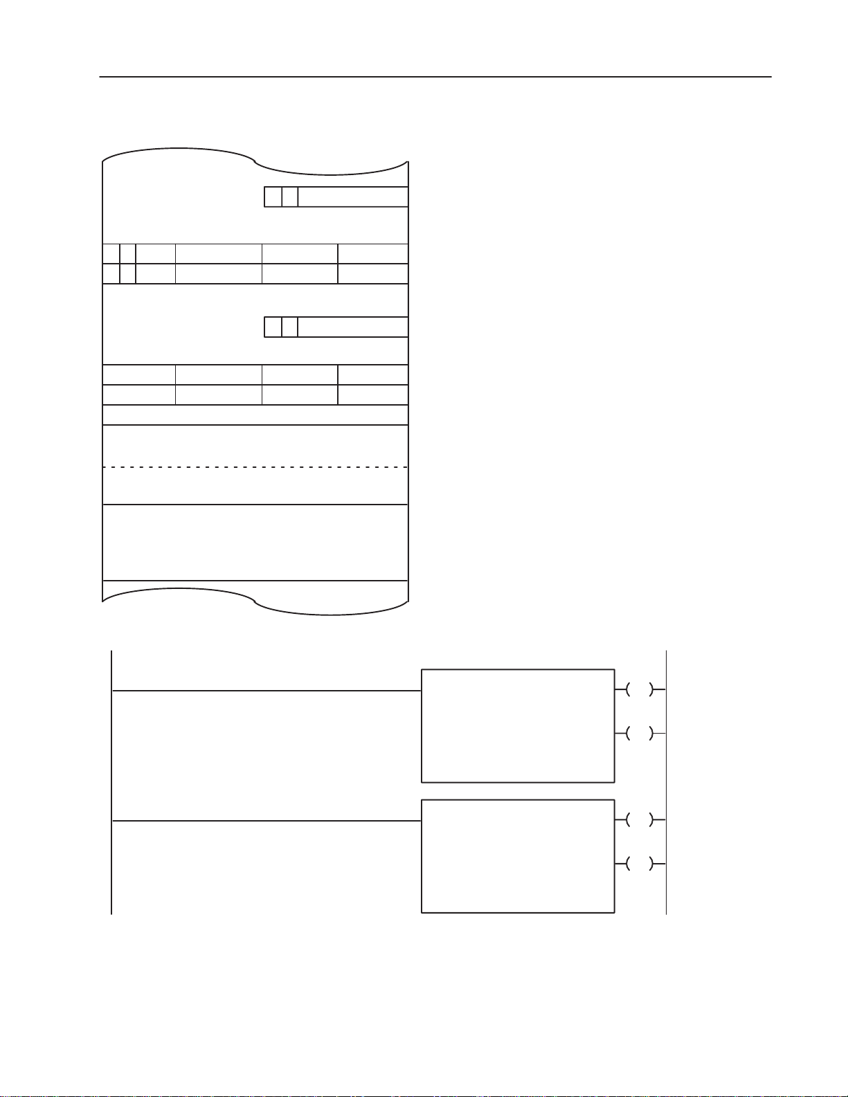
Figure 3.17
Example Bidirectional Block Transfer
3–29Programming and Operation
~~~
~
RW
1
~
~
~
~
Data Table
130
1
130
200
3 0 0 141
Block Transfer Read File
10 Words, Max.
Addresses Available
for Storage
Block Transfer Write File
64 Words, Max.
W
R
Block length code
1
1
W
1R1
010
013
Output image table low byte
~
~
040
Data Addresses store the module
address, rack 1, module group 3, slot 0.
041
~
~
~
~
Input image table low byte
113
140
Storage locations of file addresses
200
Up to 10 words of data are read from the
module and located into the data table starting
211
at word 2008 when default block length is
212
programmed.
277
300
Up to 64 words of data are written to the
bi-directional block transfer module starting
from word 300
programmed.
377
when default block length is
8
BLOCK TRANSFER READ
DA T A ADDR:
MODULE ADDR:
BLOCK LENGTH:
FILE:
200–277
BLOCK TRANSFER WRITE
DA T A ADDR:
MODULE ADDR:
BLOCK LENGTH:
FILE:
300–377
013
EN
040
130
00
07
113
DN
07
013
EN
041
130
00
Publication 1771-UM002A–EN–P – May 2000
06
113
DN
06
10529
Page 52

3–30 Programming and Operation
Programming Considerations
This section describes how block transfer concepts can be applied to
programming the stepper positioning assembly. It is assumed that an
Industrial Terminal (cat. no. 1770-T3) will be used and that the
programmable controller is either an Allen-Bradley Mini-PLC-2/15
or PLC-2/30.
Programming Strategy
Move commands and moveset blocks containing data of different
block lengths can be transferred to the stepper controller module by
programming one unconditional write block transfer instruction with
a write block transfer file. Data blocks can be moved alternately into
the write block transfer file and immediately transferred to the
stepper controller module during the next block transfer.
File-to-file-move instructions are used to transfer data blocks from
their storage locations in the data table to the write block transfer
file. When a transfer is needed, program logic enables the file-to-file
move instruction. The block transfer is automatic because it is
unconditionally programmed.
Status data from the stepper controller module is transferred using
one unconditional read block transfer instruction. The data is
transferred into a buffer file where it is held temporarily until the PC
processor can verify that the transfer and the data are valid. Valid
data can be moved to a final storage file where it can be manipulated
by program logic. Invalid data is not moved from the buffer file but
over-written by the next block transfer read operation. Examination
of the read block transfer done bit is the condition for moving valid
data into its final storage file. Following a transfer, the stepper
controller module will set itself for the alternate read or write
operation when the block lengths are set to the default value.
Block Length
The block length of read or write block transfer instructions must be
set to default value, 00, causing the default mode of the stepper
controller module to automatically perform block transfer
handshaking. The stepper controller module will toggle from a write
operation to a read operation and vice-versa.
Important: Do not confuse block transfer handshaking (which
verifies a successful transfer of data) with other
recommended handshaking that examines the status bits
in the axis status word. Status bits verify that a
command and/or data have been received by the stepper
controller module and indicate when the command can
be disabled.
Publication 1771-UM002A–EN–P – May 2000
Page 53

3–31Programming and Operation
When the block length of the read block transfer instruction is set to
the default value, 00, the stepper controller module will
automatically establish the default number of status words to be
transferred; either four, seven or ten words. This number is
determined by the highest address of a pulse output expander module
contained in the chassis. For example, if the highest expander
address were 1, 2, or 3, then the read block transfer would be four
words, seven words or ten words, respectively. The remaining words
of the 64 word default read block not used by the module can be
used for timer/counter accumulated values and/or bit/word storage.
Refer to Figure 3.17.
When the block length of the write block transfer instruction is set to
the default value, 00, the stepper controller module will expect to
receive 64 words. The write block transfer file should also be 64
words long. During a write block transfer operation, 64 words will
be transferred. However, all 64 words need not contain data.
When transferring a moveset of less than 64 words, the unused
balance of the moveset or write block transfer file must be cleared or
voided. This can be done by loading zeros into all unused words or
by programming the skip bit in the single move control word of each
move to be skipped. The write block transfer file will contain data
from the previous transfer. If the next moveset to be transferred
contains fewer words of data than the previous transfer, the balance
of the file will not be over-written but will accompany the new data.
The stepper controller module, unable to distinguish between new
and previous data, will operate on the entire transfer.
WARNING: To avoid unpredictable machine
operation with possible damage to equipment and/or
!
This can be done using only one of the following methods:
A. Loading zeros into all words remaining unused in the 64
injury to personnel, be sure that the unwanted balance
of transferred data is properly voided.
word moveset file. In this case, zeros can be loaded into the
moveset files initially when move data is programmed.
For example, if only the first seven moves of a moveset are
to be used, the last three moves (16 words) can be loaded
with zeros. The zeros will over-write any data that could
remain in the write block transfer file from the transfer of a
previous moveset.
Publication 1771-UM002A–EN–P – May 2000
Page 54

3–32 Programming and Operation
B. Setting the skip bit in the single move control words
corresponding to unwanted move blocks. Program logic can
be used to set bit 02 in the 59th, 53rd, 47th word, etc. of the
write block transfer file so that respectively the last, next to
last, third from last, etc. move blocks of a moveset are
skipped by the stepper controller module.
C. Programming the block transfers of multiple movesets so that
each moveset is the same size or larger than the previous one.
It will be necessary to clear the write block transfer file after
the last moveset has been transferred in order to start the
sequence again.
Programming Commands
When a command is transferred to the stepper controller module, the
transfer will contain either one word or four words of new data. This
will depend on whether the moveset control word (MCW) alone, or
the moveset control word, offset, and preset words are moved into
the write block transfer file just prior to the transfer. Moveset data
that remained in the write block transfer file from a previous transfer
will accompany the command data. This unwanted moveset data
may or may not have to be voided depending upon which command
bit is set.
Start MCW, bit 00
Usually accompanied by the first moveset after a reset or stop
command, or after a profile has ended. The first moveset could have
been previously transferred without the start command. If so, the
stepper controller would process the data accompanying the
command, load it into the working or storage area (writing over any
previously loaded data) and execute the start of the moveset.
Reset and Stop MCW, bits 04 and 06
The stepper controller module clears all moveset data in both the
working and storage areas and ignores all accompanying data when
it receives a reset or stop command.
Offset MCW, bit 13
A block of four words is required to transfer an offset command with
data (preset words must be included even if unused). The moveset
data (unwanted) accompanying the offset command will be
processed by the stepper controller module.
Choose one of the methods for voiding unwanted data described in
“Block Length,” above.
Publication 1771-UM002A–EN–P – May 2000
Page 55

3–33Programming and Operation
Jog reverse and Jog forward MCW, bits 14 and 15
When either software jog command bit 14 or 15 is enabled in the
user program, the jog move will be executed if jog data had been
previously transferred. The software jog command can be
transferred to the stepper controller module with jog moveset data (1
move) or can be transferred by transferring only a moveset control
word with bit 14 or 15 set. When the software jog command is
transferred in the moveset control word alone, jog data (identified by
SMCW load jog bit 03 set for an axis) must already be stored in the
stepper controller module.
The stepper controller module ignores all but the first 10 words of
jog moveset data if the load jog command bit is set. If this bit is not
set, only the first four words of the moveset will be processed.
Override MCW, bit 17
An override moveset block of one to ten moves is required to
transfer an override command. When the override command and
data are received by the stepper controller module, the storage data
in the module will be cleared and the override data will become the
new working moveset. Refer to section titled “Moveset Block,”
Override bit 17. Any moveset data (unwanted) accompanying the
offset command will be processed by the stepper controller module.
Choose one of the methods for voiding unwanted data described in
Block Length, above.
Initialization Preset MS Preset, bit 17
All moveset data is ignored by the stepper controller module when it
receives an initialization preset command unless the load jog bit is
set in the first move block. The initialization preset cannot be
transferred after the move profile has begun.
Load jog SMCW, bit 03
Must be set to identify the moveset block as data. See Jog reverse
and Jog forward above.
Data Table Sizing Considerations
The data table files that are used to store and transfer data to and
from the stepper controller module should be considered with respect
to available data table space. Typically, the data table will contain
the following files:
• 1 or more moveset files per axis- four overhead words plus six
words per move, 64 words maximum.
• 1 jog file per axis - ten words to store jog data.
Publication 1771-UM002A–EN–P – May 2000
Page 56

3–34 Programming and Operation
Data Table File 1 Move
status file 4 4 10
temporary status buffer 4
write block transfer file 10
jog file 10 10 3 x 10
moveset file
Total
[1]
not be used. Set the block length to the maximum number of words transferred.
• 1 write block transfer file - 64 words for the temporary storage of
data to be write block transferred.
• 1 read block transfer (buffer) file - When the block transfer read
instruction is set to default, 00, this file uses four words for axis
1, seven words for axis 2 or ten words for axis 3. The balance of
this file can store other data because the balance is not used by
the read block transfer instruction.
• 1 status file - four words for axis 1, seven words for axis 2 or ten
words for axis 3, for storing validated status data.
The minimum and maximum number of words typically required
for the files are summarized in Table 3.A.
Table 3.A
Size of Data Files
Number of Data Table Words
10 Move
1 Axis
[1]
[1]
10
__
38
When programming only one move for 1 axis, block length default values need
1 Axis
4 10
64 64
64
_____
146
10 Move
3 Axis
[2]
3 x 64
_______
306
Publication 1771-UM002A–EN–P – May 2000
[2]
If multiple movesets are programmed, add 64 words maximum per axis per addi-
tional moveset.
Data Table Documentation Forms
Data table forms are available for recording the assignment of files
(publication 5044) and for recording move data contained in the files
(Moveset Data form). These forms can be found at the end of this
manual and should be reproduced as needed.
Data Table Expansion
The Mini-PLC-2/15 and PLC-2/30 data tables are factory configured
to 128 words. The number of 128-word data table sections can be
increased to store the positioning profile data. This can be done
using the data table configuration function. Press [SEARCH][5][0]
on the industrial terminal keyboard when the PC processor is in
program mode. Enter the required number of 128-word sections.
The [CANCEL COMMAND] key terminates this function.
Page 57

3–35Programming and Operation
Important: Increasing the size of the data table by 128-word
sections reduces the amount of words for user program
by the same amount.
Handshaking
Handshaking is the exchange of commands and/or data with status
information between the PC processor and stepper controller
module. Handshaking is normally used to ensure successful block
transfers independent of data transfer times. The stepper positioning
assembly uses any one of three handshaking cycles depending on the
content and purpose of the transfer. The steps of the handshaking
cycles are summarized below.
CYCLE 1 Transferring a command bit (start, jog forward, jog
reverse, override, initialization preset, load jog) with or without
accompanying data.
1. Enable the transfer containing the command bit (with or without
accompanying data).
2. Observe that the command verify bit is set in the status word by
the stepper controller module.
3. Clear the command bit.
4. Observe that the command verify bit is then cleared in the status
word by the stepper controller module.
CYCLE 2 Transferring a reset or stop command.
1. Transfer the reset or stop command.
2. Observe that the reset or stop bit is set in the status word.
3. Clear the command bit. The reset or stop status bit will not be
cleared until the first move of the next moveset begins.
CYCLE 3 Transferring data with no command bit.
1. Observe whether the data receive (toggle) bit in the status word is
set or reset.
2. Enable the transfer of data.
3. Observe that the data receive toggle bit changes to the opposite
state.
Command bits are contained in the moveset control word, MS preset
word and single move control word. Status bits are contained in the
status word. Command bits which directly correspond to bits in the
status word during the handshaking cycle are presented in Table 3.B.
Publication 1771-UM002A–EN–P – May 2000
Page 58

3–36 Programming and Operation
The command verify (status) bit will be reset whenever:
A. the stepper controller module receives a transfer where none
of the following command bits are set: start (bit 00), stop (bit
06), offset (bit 13), jog (bit 14 or 15), override (bit 17),
initialization preset (MS preset, bit 17), and load jog
(SMCW, Bit 03), or
B. a reset command (bit 04) is received.
The reset and stop bits will not be set in the status word until the
pulse output expander module has actually performed the reset or
stop command. Once set, the reset and stop (status) bits remain set
until another move begins.
The data receive bit (bit 01) in the status word will toggle whenever
the stepper controller module receives any new block transfer data
and/or command.
A command bit can be transferred to the stepper controller module
by setting a command bit in the moveset control word and block
transferring the moveset control word to the module. The moveset
control word can be transferred alone (1-word transfer), with the
offset and preset words (4-word transfer) or with a moveset block
where the transfer can vary in length by 6-word increments from 10
words to 64 words. The moveset control word must always have its
axis address bit(s) set. This is the only way that the stepper
controller module can identify for which axis the transfer is intended.
Move data cannot be transferred to the stepper controller module
unless accompanied by the moveset control word, offset and preset
words.
Publication 1771-UM002A–EN–P – May 2000
Page 59

Table 3.B
Corresponding Handshake Bits
Moveset Control Word Moveset Control Word
Command Bit Function Bit
Start 00 Command verify 00
3–37Programming and Operation
Reset 04
Stop 06
Offset 13 Command Verify 00
Software jog reverse 14 Jog reverse and Command verify 14
Software jog forward 15 Jog forward and Command verify 15
Override 17 Command verify 00
MS Preset Word
Command Bit
Initialization preset 17
Single Move Control Word
Command Bit
Load jog 03 Command verify 00
1
Once set, the reset and stop status bits remain set until another move begins.
1
Reset 05
1
Programmed Stop and Command
Verify
Command verify 00
06
00
00
00
Block Transfer Timing
The time required for a block transfer read or write operation for
PLC-2 Family processors depends on the system scan time(s), the
number of words to be transferred, the I/O configuration and the
number of enabled block transfer instructions in the ladder diagram
program during any program scan. A block transfer module will not
accept another transfer until finished processing the previous
transfer. For a worst case calculation of the time between block
transfers, assume that the number of enabled block transfer
instructions during any program scan is equal to the number of block
transfer modules in the system. Also assume that the stepper
controller module is operating in default mode so that 64 words or 10
words are transferred in the write or read operation, respectively.
The stepper controller module will toggle, when done, from one
operation to the other in the next program scan.
Publication 1771-UM002A–EN–P – May 2000
Page 60

3–38 Programming and Operation
The method for calculating the worst case time between block
transfers will be covered for the following cases: PLC-2/30 remote
and local systems, and Mini-PLC-2/15 controller.
PLC-2/30 (PLC-2/20) Remote System
The system scan time for a remote PLC-2/30 or PLC-2/20 system is
the sum of the processor scan time, the processor I/O scan time
(between processor and remote distribution panel), and the remote
distribution panel I/O scan time. Assume that for a remote system,
the remote distribution panel can process only one block transfer
operation per remote distribution panel scan.
The procedure for calculating the worst case time between transfers
under normal operating conditions can be done in four steps.
1. Write down the known facts.
2. Calculate the system values that are determined by the system
configuration.
• Program Scan PS = (5ms/1K words) x (number of program
words)
• Processor I/O Scan PIO = (0.5ms/rack number) x (declared
rack numbers)
• Remote Distribution I/O Scan RIO = (7ms/chassis) x (number
of chassis)
• Number of Words Transferred W = default values of the
module
3. Calculate the block transfer time TW for the write operation and
TR for a read operation.
TW = PS + PIO + 2 RIO + .5W + 13
TR = PS + PIO + 2 RIO + .5W + 4
These equations are valid for up to 10,000 cable feet between the
remote distribution panel and remote chassis and for a baud rate of
57.6k, or 5,000 cable feet at 115k baud rate.
4. Calculate the worst case system time ST between transfers.
ST = sum of transfer times of all block transfer modules in a
system taken worst case (read or write).
Publication 1771-UM002A–EN–P – May 2000
Page 61

PLC–2/30
3–39Programming and Operation
Example Problem 1
A PLC-2/30 programmable controller is controlling 4 I/O racks in
remote configuration (Figure 3.18). A 3-axis stepper positioning
assembly is located in each rack. Assume that the stepper controller
module is operating in default mode and that the ladder diagram
program contains 4K words (K 1024). There are no other block
transfer modules in the system.
Figure 3.18
Remote System Example
1772–SD
10,000’ System
1771–AS
1771–QA
Rack No. 1
1771–AS
1771–QA
1771–AS
Rack No. 2
1771–QA
Rack No. 3
1771–QA
1771–AS
Rack No. 4
What is the worst case time between two consecutive write block
transfers for this system when a 64 word moveset block is
transferred to the stepper positioning assemblies and a ten word
status block is returned to the PC processor?
Solution
1. Write down the known facts.
10535
Program length = 4K words
Number of chassis = 4 rack numbers
Number of default block transfer words = 64 words (write),
10 words (read)
2. Calculate the system values.
Publication 1771-UM002A–EN–P – May 2000
Page 62

3–40 Programming and Operation
Processor Scan Time PS = (5ms/lK words x (4K words) =
20ms
Processor I/O Scan Time PIO = (0.5 ms/rack number) x (4
rack numbers) = 2 ms
Remote Distribution I/O Scan Time RIO = (7 ms/chassis) x
(4 chassis) = 28ms
Number of Words Transferred = 64 (write) or 10 (read)
3. Calculate the block transfer times, TW for a write and TR for a
read operation.
TW = PS + PIO + 2(RIO) + .5W + 13
TW = 20 + 2 + 2(28) + .5(64) +13
TW = 123ms (write)
TR = PS + PIO + 2(RIO) + .5W + 4
TR = 20 + 2 + 2(28) + .5(10) + 4
TR = 87ms (read)
4. Calculate the worst case system time ST between 2 consecutive
write block transfers.
ST = 4TW + 4TR
= 4(123) + 4(87)
= 492 + 348
= 840ms
This is the worst case time between two consecutive write block
transfers in the 4-chassis remote configuration described in example
problem 1 (enabled stepper assembly in each chassis).
PLC-2/30 Local System
The system scan time for a local PLC-2/30 system is the program
scan time plus the processor I/O scan time Each block transfer
module will be updated during a program scan.
The procedure for calculating the worst case time between transfer
can be done in four steps.
1. Write down the known facts.
2. Calculate the system values that are determined by the system
configuration.
• Program Scan PS = (5ms/lK words) x (number of program
words)
Publication 1771-UM002A–EN–P – May 2000
• Processor I/O Scan PIO (0.5ms/rack number) x (number of
declared rack numbers)
• Number of words transferred W default values of the module
Page 63

PLC–2/30
3–41Programming and Operation
3. Calculate the block transfer time T for the read and write
operation.
T = 0.1ms + (.075ms/word x number of words transferred)
The same equation is used for either read or write transfer times.
4. Calculate the worst case system time ST between transfers.
ST = PS + PIO + T(1) + T(2) + T(3) +...
Example Problem 2
A PLC-2/30 programmable controller is controlling four I/O racks in
a local configuration (Figure 3.19). Otherwise this example problem
is identical to example problem 1.
Figure 3.19
Local System Example
1771–AL
1771–QA
Rack No. 1
1771–AL
1771–QA
1771–AL
Rack No. 2
Solution
1. Write down the known facts.
Program length = 4K words
Number of chassis = 4 rack numbers
Number of default block transfer words = 64 words (write),
10 words (read)
2. Calculate the system values.
1771–QA
Rack No. 3
1771–AL
1771–QA
Rack No. 4
10536
Publication 1771-UM002A–EN–P – May 2000
Page 64

3–42 Programming and Operation
Processor Scan Time PS = (5ms/lK words) x (4K words) =
20ms.
Processor I/O Scan Time PIO = (0.5ms/rack number x (4
rack numbers) = 2ms
Number of Words Transferred = 64 (write) or 10 (read)
3. Calculate the block transfer times T for the write and read
operation.
T = 0.1 + (.075ms/word x 64 words)
= 0.1 + 4.8
= 4.9ms (write)
T = 0.1 + (.075ms/word x 10 words)
= 0.1 + .75
= .85ms (read)
4. Calculate the worst case system time ST between 2 consecutive
write block transfers.
The stepper controller module toggles to a read operation in the scan
following completion of the write operation.
ST = PS + PIO + T(1) + T(2) + T(3) + T(4) (writes)
PS + PIO + T(1) + T(2) + T(3) + T(4) (reads)
ST = 2PS + 2PIO + 4T (write) + 4T (read)
= 2(20) + 2(2) + 4(4.9) + 4(.85)
= 40 + 4 + 19.6 + 369
= 67 ms
This is the worst case time between two consecutive write block
transfers in the 4-chassis local configuration described in example
problem 2 (enabled stepper assembly in each chassis).
Mini-PLC-2/15 Controller
The program scan and I/O scan are consecutive and are considered as
a single processor scan. The Mini-PLC-2/15 scan time varies
typically from 18 to 24ms for a 1K program and one I/O rack. Each
block transfer module will be updated during a program scan.
The procedure for calculating the worst case time between transfers
can be done in three steps.
1. Write down the known facts and system values.
Publication 1771-UM002A–EN–P – May 2000
• Processor Scan time PS = 24ms
• Number of Words Transferred W default value of the module
2. Calculate the block transfer time T for the read and write
operation.
Page 65

3–43Programming and Operation
T = 0.1ms + (.16ms/word x number of words transferred)
The same equation is used for either read or write transfer times.
3. Calculate the worst case system time ST between transfers.
ST = PS + T(1) + T(2) + T(3) + ...
Example Problem 3
A Mini-PLC-2/15 programmable controller is controlling one 3-axis
stepper controller assembly in its I/O rack. The ladder diagram
program contains 2K words. Otherwise, this example problem is
identical to example problem 1.
Solution
1. Write down the known facts and system values.
• Program length = 2K words
• Processor Scan Time PS = (24ms/lK words) x (2K words) =
48ms
• Number of words transferred W = 64 (write, 10 (read)
2. Calculate the block transfer time T for the write and read
operation.
T = 0.1ms + (.16 ms/word x 64 words) (write)
= 0.1 + 10.24
= 10.34ms (write)
T = 0.1ms + (.16ms/word X 10 words) (read)
= 0.1 + 1.6
= 1.7ms (read)
3. Calculate the worst case system time ST between two consecutive
write block transfers.
ST= PS + T (write) + PS + T (read)
= 48 + 10.34 + 48 + 1.7
= 108 ms
This is the worst case time between two consecutive write block
transfers for the Mini-PLC-2/15 controller as described in example
problem 3.
Publication 1771-UM002A–EN–P – May 2000
Page 66

3–44 Programming and Operation
Application
Considerations
The values which can be selected for ramp and decel times, the final
rate, and final position allow a very wide variety of move profiles to
be programmed. However there are some constraints which, if not
taken into consideration, can result in a programming error when the
move profile is executed. These constraints, for the most part,
should be considered when programming long acceleration times
with brief but relatively high final rates.
Selected values can be tested on paper using one or more of the
following algebraic equations as appropriate. This can be done by
substituting the selected values into the equation, performing the
required mathematical manipulations and seeing whether the
constraints are satisfied. Values can also be tested by running the
program with the stepper translator disconnected. If the constraint(s)
are not met as indicated by a programming error, then new values
can be selected and tested until allowable values are found.
Move Duration
A move must remain at the programmed final rate for at least 20ms
in order to avoid a programming error. This constraint must be
satisfied for all moves but could likely be exceeded in moves
covering short distances at high final rates. This constraint can be
met in either of two ways:
• Decide where the final position must be. Then select and/or
adjust the programmed ramp time, decel time (if part of the
move) and/or final rate values accordingly.
• Select appropriate programmed ramp time, decel time (if part of
the move) and/or final rate values and accept the resulting final
position.
The following equation can be used to test this constraint.
Equation 1.
RT (FR + IR)
where:
RT = ramp time
FR = final rate
IR = initial rate
DT = decel time (in the continuous mode, this term is zero
for all but the last move)
DELPOS = Difference in ELapsed POSition, the difference
in number of pulses between the starting position and
programmed final position of the move
+ FR
DT
22
+ 0.02 <
DELPOS
Publication 1771-UM002A–EN–P – May 2000
Page 67

Rate
FR
3–45Programming and Operation
The following three examples show how this equation can be used.
Example Problem 1: Single-step mode or independent mode.
For the next move of a move profile, the change in move position
from beginning to end (DELPOS) must be 26k pulses. Determine
the maximum allowable final rate (FR) when using equal ramp and
decel times of 4 seconds.
The parameters of the equation (IR, FR, RT and DELPOS) and a
sketch of the move are shown in Figure 3.20.
Figure 3.20
Single Step or Independent Mode
20 ms
IR
Start
Position
RT DT
DEL POS
Final
Position
Position
10530
Solution
Write down the known facts.
1. RT = DT = 4 seconds
DELPOS = 26k pulses
IR = 0 (The initial rate of a move in the single step or
independent mode is zero by definition.)
Find FR, the maximum final rate.
4(FR + 0)
+ FR
4
22
+ 0.02
<
26k
Choose a value for FR, say 10k pulses per second.
Publication 1771-UM002A–EN–P – May 2000
Page 68

3–46 Programming and Operation
4(10k + 0)
+ 10k
4
22
+ 0.02
<
26k
20k + 20.2k <26k
40.2k <
26k This exceeds the constraint.
The selected value of 10k was too large. Try FR = 6k.
4(6k + 0)
12K + 12.12K <
24.12k <
26k This is within the constraint.
+ 6k
26k
4
22
+ 0.02
<
26k
The final rate of 6k pulses per second is allowable and can be used.
Any value greater than approximately 6.4k pulses would cause a
programming error when the move is executed.
Example Problem 2: Continuous Mode (except the last move)
Determine the minimum final position (shortest allowable travel) of
a move when the final position and final rate of the previous move
were 100k pulses and 2k pulses per second, respectively, and the
ramp time and final rate of the current move are RT = 3 seconds and
FR = 10k pulses per second.
The parameters of the equation (IR, FR, RT and DELPOS) and a
sketch of the move are in Figure 3.21.
Figure 3.21
Continuous Mode (Except the Last Move)
Rate
FR
IR
RT
DEL POS
Start
Position
20 ms
Final
Position
Position
10532
Publication 1771-UM002A–EN–P – May 2000
Solution: Write down the know facts.
Page 69

3–47Programming and Operation
RT = 3 seconds
FR = 10k pulses per second
IR = 2k pulses per second (final rate of previous move)
DT = 0 (decel time is zero in all moves except the last in the
continuous mode, by definition)
Find DELPOS, then add this figure to the final position of the
previous move (100K) to determine the minimum final position that
can be programmed for the move.
3(10k + 2k)
18k + 0.2K <
18.2k <
+ 10k
DELPOS
DELPOS
0
22
+ 0.02
<
26k
The move final position value must be at least 18.2k pulses beyond
the previous move in order to ensure that the final rate will be
maintained for 20ms. Therefore the minimum allowable
programmed final position for the move is 118,200 pulses, obtained
from adding the calculated value (18.2k) to the final position of the
previous move (100k).
Example Problem 3: Last Move in a Continuous Mode
The last move of a continuous profile must stop at a final position of
742k pulses. Determine if a selected decel time of 2 seconds is
acceptable if the final rate and final position of the previous move
were 12k pulses per second and 680k pulses, respectively, and the
ramp time and final rate (before decel) of the current move are RT =
6 seconds and FR = 6k pulses per second, respectively.
Publication 1771-UM002A–EN–P – May 2000
Page 70

3–48 Programming and Operation
Rate
Position
The parameters of the equation (IR, FR, RT and DELPOS) and a
sketch of the move are shown in Figure 3.22.
Figure 3.22
Last Move in a Continuous Mode
IR
20 ms
FR
RT
DEL POS
Start
DT
Final
Position
Solution: Write down the known facts.
RT = 6 seconds
IR = 12k pulses per second (final rate of previous move)
FR = 6k pulses per second
DELPOS = 62k pulses (742k pulses - 680k pulses)
6(6k + 12k)
54k
+ 6k
DT
2
DT
2
+ 0.02
+ 0.02
6k
DT
2
<
DT
2
1.31
+ 0.02
<
<
+ 6k
8k
1.33
DT
<
22
62k
+ 0.02
<
62k
Therefore, a decel time of 2 seconds is acceptable for the move.
Position
10531
Publication 1771-UM002A–EN–P – May 2000
Reversing Direction During a Continuous Sequence
In order to reverse direction during a positioning sequence in the
continuous mode, a move to 0Hz rate must be achieved. The
procedure for achieving a 0Hz rate as stated in the paragraph titled
“Decel and Position Considerations for a 0Hz Rate Move” should be
followed.
Page 71

3–49Programming and Operation
Decel and Position Considerations for a 0Hz Rate Move
A 0Hz rate move must be used when the profile is brought to a stop
such as when reversing direction. When programming a 0Hz rate
move, the ramp time and decel time are not used by the stepper
controller module regardless of whether or not they are programmed.
Only the rate (0Hz) and final position values are entered. Either one
of the following equations can be used to verify that a move to 0Hz
rate allows 20ms of final rate before the decel begins. This
constraint should be considered when any move in the continuous
mode except the last move is brought to a 0Hz rate.
If the actual executed decel time T is more important than the final
position, then equation 2a should be used to calculate the correct
DELPOS from which the correct programmed final position value
can be obtained.
DELPOS |Programmed final position - starting position|. The ||
symbols means absolute value; disregard the sign in the answer.
If a required final position of the move to 0Hz rate is more important
than the actual executed decel time, equation 2b should be used to
verify that the decel time T does not exceed 9.99 seconds.
Equation 2a: Final Position Value
DELPOS =
T
IR
2
and
+ 0.04
Final Position Value = DELPOS + Final Position of the Previous
Move.
Equation 2b: Actual Decel Time
T
DELPOS
IR
– 0.04
where:
DELPOS = The difference in number of pulses between the
starting position of the move and the programmed final
position of the move.
T = The actual time of the decel in seconds as executed by
the positioning system (programmed ramp and decel times of
the move are ignored).
IR = Initial rate in pulses per second (final rate of the
previous move).
Publication 1771-UM002A–EN–P – May 2000
Page 72

3–50 Programming and Operation
The parameters of the equation (DELPOS, T and IR) and a sketch of
the move are shown in Figure 3.23.
Figure 3.23
0Hz Rate Move
Rate
IR
Start
Position
Example Problem 1:
20 ms
DEL POS
T
Final
Position
Position
10533
The seventh move of a profile in continuous mode must be brought
to 0Hz rate so that the profile can return to its starting point value.
The final rate and final position of the previous move are 16k pulses
per second and 510k pulses, respectively. The seventh move must
reach a 0Hz rate at 620k pulses. What decel time should be
programmed? How can this move be achieved?
Solution: Write down the known facts.
IR = 16k (final rate of previous move)
DELPOS = 110k (620k - 510k pulses)
2 DELPOS
T
2(110k)
T
220k
T
IR
IR
IR
– 0.04
– 0.04
– 0.04
(Line 1)
(Line 2)
(Line 3)
T = 13.75 seconds
Publication 1771-UM002A–EN–P – May 2000
Page 73

3–51Programming and Operation
This exceeds 9.99 seconds. Either the position of the 0Hz rate move
must be decreased, or the final rate of the previous move must be
raised, or the final position of the previous move must be extended
(or a combination of all three) in order to bring the decel time to
9.99 seconds or less. Assume that the DELPOS can be changed. If
the DELPOS is reduced from 110k to 80k pulses, the actual decel
time will be 10 - 0.04 = 9.96 seconds (from line 2) and within limits.
In order to reduce the DELPOS to 80k pulses, the final position of
the previous move would have to be extended by 30k pulses to 540k
pulses.
Override Ramp Time Considerations
During execution of an override move, the actual override ramp time
executed by the stepper positioning assembly will vary depending on
the rate which is being overridden.
The override move must be programmed to guarantee that both the
actual executed override ramp time and the programmed ramp time
be in the range of 0-9.99 seconds. The actual override ramp time is
defined as the time required to change from the rate-in-process when
the override command was received by the stepper controller module
to the programmed override rate. The actual override ramp time as
executed by the positioning system can be calculated using equation
3a. Equation 3b can be used to verify that a desired actual ramp time
(ORT
(ORT
be used with the maximum and minimum rates which could be
overridden to ensure that the actual override ramp time is between 0
and 9.99 seconds.
) is possible by ensuring that the programmed ramp time
Act
) lies between 0 and 9.99 seconds. These equations should
Prog
The following equations can be used with any (IR) rate to be
overridden.
Equation 3a: Actual Override Ramp Time
ORT
ORT
Act
Prog
|OFR–IR|
x
OFR
Equation 3b: Programmed Override Ramp Time
ORT
Prog
ORT
Act
|OFR–IR|
x
OFT
where:
ORT
ORT
Act = Actual override ramp time
Act
= Programmed override ramp time
Prog
OFR = Override final rate
IR = Initial rate (rate in process when override occurs)
|OFR - IR| = absolute value (if the difference is a negative
number, consider it positive.)
Publication 1771-UM002A–EN–P – May 2000
Page 74

3–52 Programming and Operation
If ORT
(<
10ms).
The equation parameters (ORT
in equation 3a is zero, then ORT
Prog
, ORT
Act
will be instantaneous
Act
, OFR, and IR) and a
Prog
sketch of the move are shown in Figure 3.24.
Example Problem 1:
An override ramp time is programmed for 6.2 seconds. What will be
the actual override ramp time if the override is enabled while a rate
(IR) of 8k pulses per second is being executed? The final rate of the
override move is 10k.
Solution: Write down the known facts.
IR = 8k pulses per second
OFR = 10k pulses per second
ORT
ORT
ORT
Act
ORT
Act
6.2 x
Act
1.24seconds
Act
= 6.2 seconds
ORT
x
Prog
|10k–8k|
10K
|OFR–IR|
OFR
6.2x
2k
10k
This is the range of 0-9.99 seconds and is therefore acceptable. If
the initial rate had been greater than 10k, then the absolute value of
|OFR-IR| (negative difference considered as if positive) would have
been used.
Publication 1771-UM002A–EN–P – May 2000
Page 75

Figure 3.24
Override Ramp Time
3–53Programming and Operation
Rate
OFR
Rate
IR
ORT
Prog
ORT
Act
Executed
Profile
IR
Not Executed
Position
Override Move
Move in Progress
A) Override Ramp Time, OFR > IR
ORT
Act
Must Not Exceed 9.99 Seconds
OFR
Programmed
Override Ramp
ORT
Slope of executed override ramp will be
equal but opposite to that of programmed
override ramp.
Prog
Move In Progress
B) Override Ramp Time, OFR < IR
Not Executed
Override Move
Executed
Profile
Position
10537
Publication 1771-UM002A–EN–P – May 2000
Page 76

3–54 Programming and Operation
Stepper Motor Acceleration Considerations
The stepper motor specifications will contain an acceleration
limitation. It will state some maximum acceptable acceleration
under load (change in pulse rate for a given duration, i.e. Hz/second).
This motor acceleration constraint must be satisfied and should be
considered especially when programming rapid accelerations to high
final rates. The following equation can be used for a move that
ramps from a 0Hz rate to a final rate.
HZ
> Final rate
second
For example, a typical acceleration limit for a stepper motor could be
10,000 pulses per second per second for a given load. Programming
a ramp time of 1 second for a change in final rate from 0 to 10,000
pulses per second would be pushing the motor to its maximum limit
of acceleration since the slope of the ramp is 10k Hz per second.
This is the fastest acceleration allowed for the motor.
motor
RAMP time
motor
The same applies if ramping from one final rate to another such as
when an override is blended with a move in process. In this case, the
change in final rates must be considered.
HZ
> Change in Final rate
second
motor
RAMP time
motor
In summary, if a programmed ramp is too quick for the
motor/machine dynamics for accelerations and decelerations, the
motor will not be able to “keep up” with the pulses being sent to it.
If this occurs, some pulses may not be executed by the stepper motor
and the indicated position value will be inaccurate. The status that is
block transferred to the PC processor would not longer state the
actual position of the motor axis.
Important: The position values represent the number of pulses sent
to the stepper translator whether or not they are
executed by the stepper motor.
Resonant Frequency
The stepper motor and load can have a resonant frequency within the
operating range of 0 to 20,000 pulses per second. When operated at
or near the resonant frequency in a steady state condition or when
accelerating or decelerating through this frequency, an increase in
noise and/or vibration can occur. In extreme cases it is possible for
the motor to oscillate and lose pulses. The resonant frequency can
vary widely depending on the characteristics of the stepper motor
and load.
Publication 1771-UM002A–EN–P – May 2000
Page 77

3–55Programming and Operation
If the resonant frequency is encountered, its effect can be dampened
or eliminated as follows:
• If encountered in a steady state condition (at or near a chosen
final rate), increase the inertial load or change the final rate.
• If encountered when accelerating or decelerating through the
resonant frequency, increase the rate of acceleration or
deceleration by programming shorter ramp or decel times.
In general, a stepper motor with no load is more apt to resonate than
one that has a load.
Accuracy of Ramp and Decel Times
Output accuracy (variation) varies from less than +2.5% at 20k Hz to
less than +1.0% at 1k Hz or lower (Table 3.C).
Table 3.C
Output Accuracy
Programmed Rate
Accuracy
20kHz-18.01kHz <+ 2.5%
18kHz-1.01kHz <+ 2.0%
1kHz-0Hz <+ 1.0%
The accuracy of the executed ramp or decel time will depend on the
programmed ramp or decel time, and the rate to which the ramp is
programmed or from which the decel is programmed. The
maximum variation in executed ramp and decel times is shown in
Table 3.D.
Table 3.D
Ramp and Decel Time Accuracy
Output Rate
Programmed Pulse
Rate
1
20,000 to 2001Hz +5%
2,000 to 101Hz +10%
100 to 51Hz +25%
50 to 2Hz +50%
1 Rate achieved by a ramp, or the rate from which a decel begins.
2 In addition, 20ms could be added or subtracted to the value of the ramp or
decel times between 0 and 1 second.
Variation in
Ramp/Decel
Time
2
2
2
Publication 1771-UM002A–EN–P – May 2000
Page 78

3–56 Programming and Operation
Minimum Move Time
A minimum “move in progress” time is required by the stepper
controller module to process the next move of a sequence, and to
evaluate and act on incoming commands. Every move sent from the
stepper controller module to a pulse output expander module must
have a duration long enough to allow the stepper controller module
to service the remaining expander modules, process any new
commands and return to the original expander module before the
move has ended. This minimum move duration must be long enough
to allow any programmed combination of events in any mode of
operation. If not, a programming error and system fault will result.
However, if jog or move data, offsets or overrides are not transferred
to the stepper controller while a profile is being executed, then the
shortest executable move time can be used as stated in Table 3.E.
Table 3.E
Minimum Move Time
No. of
Axes
1 65ms 40ms
2 110ms 60ms
3 155ms 80ms
Worst Case Shortest
Executable
Publication 1771-UM002A–EN–P – May 2000
Page 79

Example Programs
Chapter
4
General
1-Axis Program
Two example programs are presented in this chapter. The purpose of
these programs is to illustrate the procedure and documentation that
should be used and to explain the relationship between the ladder
diagram program, positioning profile(s) and move data.
The ladder diagram program presented in this section is written for a
1-axis machine application having a positioning profile of 10 moves.
Values for ramp time, final rate, decel time and final position for
each move can be programmed using an industrial terminal and a
Mini-PLC-2/15 or PLC-2/30 programmable controller in a local or
remote system configuration. The program would have to be
modified (substitute multiple get/put instructions for file-to-file
move instructions) in order to use a PLC-2/20 controller. The
following operational functions can be selected when programming
the positioning profile.
• Controlled stop
• Reset
• Initialization preset
• Software jog forward
• Software jog reverse
• Jog rate
• Type of profile
• Profile length
Profiles that are longer than 10 moves (one moveset) can be
programmed by adding movesets. This can be done by
programming additional file-to-file move instructions and entering
move data in their corresponding files. Also, user-supplied inputs to
the pulse output expander module can provide the following options:
• Hardware jog forward
• Hardware jog reverse
• Hardware stop (E-Stop)
The program is written for a 1-axis machine application and requires
one Stepper Controller Module (cat. no. 1771-M1) and one Pulse
Output Expander Module (cat. no. 1771-OJ). The user-supplied
stepper translator that interfaces with the pulse output expander
module should accept low true inputs.
Publication 1771-UM002A–EN–P – May 2000
Page 80

4–2 Example Programs
Rate
FR=2000 P/Sec
RT=
3.00 Sec
Programming a 1-Axis Profile
The task of programming can be simplified by documenting the
desired positioning profile in the following manner.
1. Sketch the positioning profile and designate the ramp time, final
rate, final position, and decel values as needed (Figure 4.1).
Decide which of the three operating modes (continuous,
independent or single step) should be used.
Figure 4.1
Example 1-Axis Profile (Continuous Mode)
Moves 2–8
RT=1.00 Sec
FR=1800 P/Sec
FR=1500
P/Sec
FR=1100 P/Sec
Reverse Forward
RT=
3.00 Sec
Move #1
FR=800 P/Sec
FR=200 P/Sec
FR=100 P/Sec
23
6000 9000 12000 15000 16500 17500 18500 19000
4
Move 10
FR=2000 P/Sec
5
6
7
8
2. Log all move data such as ramp time, final rate, final positions
and decel values as needed, and offset/preset data if used. Use
the Moveset Data form found at the end of this manual for each
positioning profile moveset (Figure 4.2) or jog moveset (Figure
4.3).
3. Write the ladder diagram program using the example as a guide
(Figure 4.4).
4. Enter move data into corresponding data table files associated
with file A of each file-to-file move instruction using the data
monitor mode of the industrial terminal (Figure 4.5). File R
displays the data moved to the write block transfer file during
operation and should be ignored during programming.
FR=050 P/Sec
9
19200
RT=
2.00 Sec
Position
10602
Publication 1771-UM002A–EN–P – May 2000
Page 81

Counter Addr:
0
Figure 4.2
Example 1-Axis Profile Moveset
ALLEN-BRADLEY
Programmable Controller
Moveset Data
(October, 1982)
HEXIDECIMAL DATA MONITOR
FILE–TO–FILE MOVE
033 1 064
Axis No.: File Length:
4–3Example Programs
File A: to Moveset No.: File R: to
Position FILE A DAT A Description Move
1
2
3
4
5
6
7
8
9
10
11
12
13
14
15
16
17
18
19
20
21
22
23
24
25
26
27
28
29
30
31
32
400 477 1 500 577
Position FILE A DAT A Description Move
0
1
0
0
0
0
0
0
0
0
0
0
C
0
0
0
3
0
2
0
0
0
1
0
0
0
0
0
0
0
C
0
0
0
1
0
1
8
0
0
1
0
0
0
0
0
0
0
C
0
0
0
1
0
1
5
0
0
1
0
0
0
1
0
0
0
C
0
0
0
1
0
1
1
0
0
1
0
0
0
1
0
0
0
C
0
0
0
1
0
0
8
0
0
1
0
0
0
0
0
0
0
0
0
6
0
0
0
0
0
9
0
0
0
0
0
2
0
0
0
0
0
5
0
0
0
0
0
MCW
Offset
MS Preset
LS Preset
SMCW
Ramp
Rate
Decel
MS Pos
LS Pos
SMCW
Ramp
Rate
Decel
MS Pos
LS Pos
SMCW
Ramp
Rate
Decel
MS Pos
LS Pos
SMCW
Ramp
Rate
Decel
MS Pos
LS Pos
SMCW
Ramp
Rate
Decel
1
2
3
4
5
33
34
35
36
37
38
39
40
41
42
43
44
45
46
47
48
49
50
51
52
53
54
55
56
57
58
59
60
61
62
63
64
0
0
1
0
5
0
C
0
0
0
1
0
0
2
0
0
1
0
0
0
1
0
5
0
C
0
0
0
1
0
0
1
0
0
1
0
0
0
1
0
5
0
C
0
0
0
1
0
0
0
5
0
1
0
0
0
1
0
0
0
C
0
0
0
0
0
0
0
0
0
1
0
0
0
1
0
2
0
C
0
0
0
2
0
2
0
0
0
3
0
0
0
0
0
0
0
MS Pos
6
LS Pos
0
SMCW
SMCW
0
Ramp
Ramp
0
0
Rate
Rate
0
Decel
Decel
7
MS Pos
MS Pos
LS Pos
LS Pos
0
SMCW
0
Ramp
0
Rate
0
Decel
0
8
MS Pos
LS Pos
0
SMCW
0
Ramp
0
Rate
0
Decel
0
MS Pos
9
LS Pos
0
SMCW
0
Ramp
0
0
Rate
0
Decel
9
MS Pos
LS Pos
0
0
SMCW
Ramp
0
0
Rate
0
Decel
0
MS Pos
0
LS Pos
6
7
8
9
10
106
Publication 1771-UM002A–EN–P – May 2000
Page 82
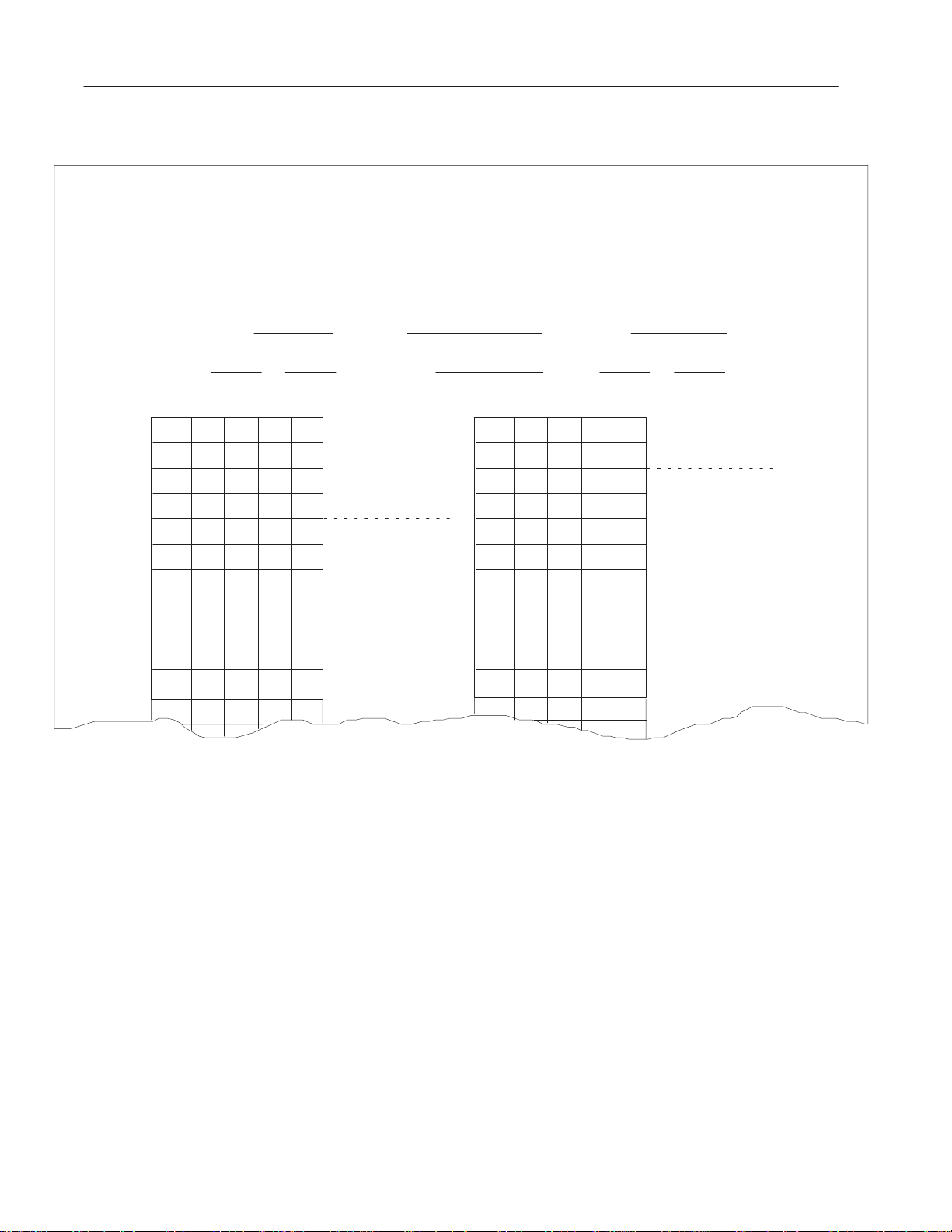
4–4 Example Programs
Figure 4.3
Example Jog Moveset with Preset Data
ALLEN-BRADLEY
Programmable Controller
Moveset Data
(October, 1982)
HEXIDECIMAL DATA MONITOR
FILE–TO–FILE MOVE
Counter Addr:
File A: to Moveset No.: File R: to
Position FILE A DATA Description Move
1
2
3
4
5
6
7
8
9
310 321 0 500 511
0
0
0
0
C
0
1
0
0099999
10
032 1 010
0
0
1
0
0
0
0
0
0
5
2
0
8
0
0
0
5
0
0
0
0
0
5
0
9
11
12
Axis No.: File Length:
Position FILE A DATA Description Move
MCW
Offset
MS Preset
LS Preset
SMCW
Ramp
Rate
Decel
MS Pos
LS Pos
SMCW
Ramp
1
33
34
35
36
37
38
39
40
41
42
43
44
MS Pos
LS Pos
SMCW
SMCW
Ramp
Ramp
Rate
Rate
Decel
Decel
MS Pos
MS Pos
LS Pos
LS Pos
SMCW
Ramp
Rate
Decel
6
7
10605
Publication 1771-UM002A–EN–P – May 2000
Page 83

LADDER DIAGRAM DUMP
110
1
15
110
2
15
Figure 4.4
Example 1-Axis Program
START
Stop (Controlled)
Stop (Controlled)
4–5Example Programs
500
06
500
07
10
112
3
03
110
4
14
110
5
16
112
6
00
112
7
00
112
8
01
112
9
01
112
02
112
11
02
Reset
Start
Initialize Preset
Jog Forward
Unlatch Jog Forward
Jog Reverse
Unlatch Jog Reversed
Jog Rate
10H
z
z
Jog Rate
1000H
500
04
500
00
502
17
310
15
500
U
OFF 15
310
14
500
U
OFF 14
316
04
316
14
Publication 1771-UM002A–EN–P – May 2000
Page 84
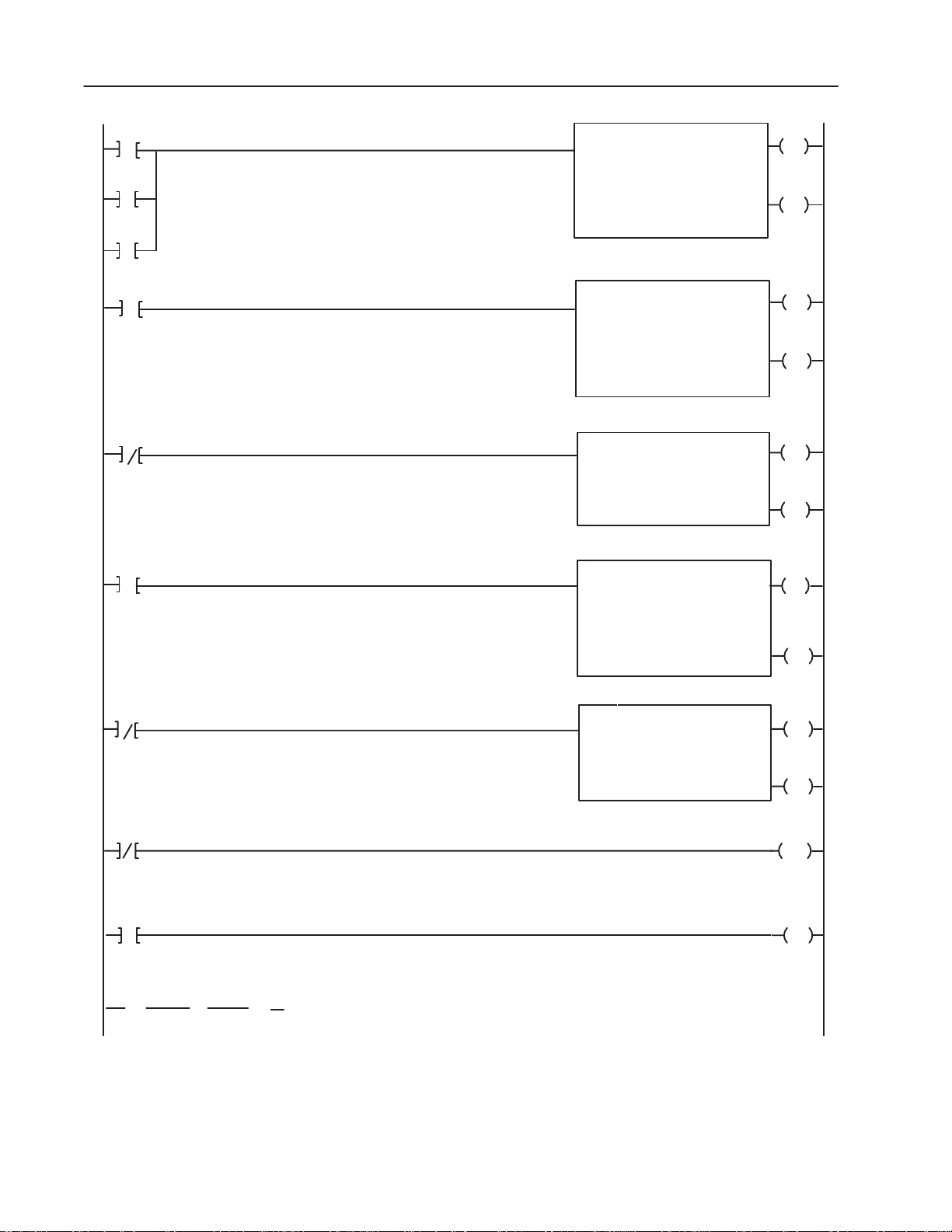
4–6 Example Programs
14
13
12
15
112
110
112
01
00
110
114
114
16
14
07
07
Jog and Preset Data
Profile Data
Buffer Status Words
FILE TO FILE MOVE
COUNTER ADDR:
POSITION:
FILE LENGTH:
FILE A:
FILE R:
RATE PER SCAN
FILE TO FILE MOVE
COUNTER ADDR:
POSITION:
FILE LENGTH:
FILE A:
FILE R:
RATE PER SCAN
BLOCK XFER READ
DATA ADDR:
MODULE ADDR:
BLOCK LENGTH:
FILE:
FILE TO FILE MOVE
COUNTER ADDR:
POSITION:
FILE LENGTH:
FILE A:
FILE R:
RATE PER SCAN
0036
0310 – 0321
0500 – 0511
0033
0400 – 0477
0500 – 0577
0030
140
00
0200 – 0277
0034
0200 – 0203
0150 – 0153
001
010
010
001
064
064
001
004
004
0036
EN
17
0036
DN
15
0033
EN
17
0033
DN
15
014
EN
07
114
DN
07
0034
EN
17
0034
DN
15
16
17
18
19
114
035
114
06
06
15
0151
[ G ]
020
0152
[ G ]
000
0153
[ G ]
000
Display Only
Block Transfer Time–Out
BLOCK XFER WRITE
DATA ADDR:
MODULE ADDR:
BLOCK LENGTH:
FILE:
0500 – 0577
0031
140
00
014
EN
06
114
DN
06
0035
TON
0.1
PR 030
AC 000
011
L
OFF 16
Publication 1771-UM002A–EN–P – May 2000
Page 85

Figure 4.5
Example Data Monitor Display and Moveset Data
HEXADECIMAL DATA MONITOR
FILE-TO-FILE MOVE
POSITION: 001
Counter Addr: 033
File Length: 064
File A : 400-477 File R: 500-577
Position File A Data File R Data
001
002 0000 0000
003 0000 0000
004 0000 0000
005
006 0300 0300
007 2000 2000 MOVE 1
008 0100 0100
009 0006 0006
010 0000 0000
01 1
012 0100 0100
013 1800 1800 MOVE 2
014 0100 0100
015 0009 0009
016 0000 0000
017
018 0100 0100
019 1500 1500
020 0100 0100 MOVE 3
021 0012 0012
022 0000 0000
023
024 0200 0200
025 1100 1100 MOVE 4
026 0100 0100
027 0015 0015
028
0100 0100
C000 C000
C000 C000
C000 C000
C000 C000
0000 0000
4–7Example Programs
Publication 1771-UM002A–EN–P – May 2000
Page 86

4–8 Example Programs
Position File A Data File R Data
029 C000 C000
030 0100 0100 MOVE 5
031 0800 0800
032 0100 0100
033 0016 0016
034 0500 0500
035
036 0100 0100
037 0200 0200 MOVE 6
038 0100 0100
039 0017 0017
040 0500 0500
041
042 0100 0100
043 0100 0100
044 0100 0100 MOVE 7
045 0018 0018
046 0500 0500
047
048 0100 0100
049 0050 0050 MOVE 8
050 0100 0100
051 0019 0019
052 0000 0000
053
054 0000 0000
055 0000 0000
056 0100 0100 MOVE 9
057 0019 0019
058 0200 0200
059
060 0200 0200
061 2000 2000
062 0300 0300 MOVE 10
063 0000 0000
064
C000 C000
C000 C000
C000 C000
C000 C000
C000 C000
0000 0000
Publication 1771-UM002A–EN–P – May 2000
Page 87
4–9Example Programs
Preset and Jog Data
Preset and jog data are programmed in a 10-word moveset. The
moveset data is contained in words 310-321 of the file-to-file move
instruction having counter address 0036 as shown in rung 12 (Figure
4.4). The preset and jog data have been logged on the Moveset Data
form (Figure 4.3). The function of the data is summarized in Table
4.A.
Important: Bits in the moveset control word and single move
control word have been set in hexadecimal notation for
convenience so that move data can be entered in
decimal numbers. The equivalence between
hexadecimal and binary must be known. Otherwise, the
binary data monitor mode would have to be used
separately for setting bit patterns in the control words.
Table 4.A
Functions of Jog/Preset Data (1-Axis Program)
Position
Number
001 310 Moveset Control word Bit 10 is set to identify axis 1. (The
002 31 1 Offset Word Ignored in this example
003, 004 312, 313 ML, LS Preset Words Preset of 25
005 314 Single Move Control
006 315 Ramp Time 0.5 second to accelerate to final rate
007 316 Final Rate 10 pulses/second or 1000
008 317 Decel Time 0.5 second to decelerate from final
009, 010 320. 321 Final Position of the jog 999,999 pulses. Allows maximum
1
Position number of the data monitor display of FFM 0036.
2
Equivalent words in file A of FFM 0036.
1
Equivalent
2
Word
Word
Description Function
hex value of 1 = 0012 in bits 12-10,
respectively.)
Bit 3 is set to identify the moveset as
Word
jog data. Bits 16 & 17 are set to
identify the single move control word.
pulses/second depending on the bit
pattern programmed in rungs 11 and
12.
rate to zero.
travel of the jog move if/as needed.
This could also be programmed as
000,000.
Publication 1771-UM002A–EN–P – May 2000
Page 88

4–10 Example Programs
Move Data
The 10-move 1-axis positioning profile (Figure 4.1) is in the
continuous mode, reverses direction at 19,200 pulses and returns to
the starting position. In order to reverse direction in this mode, a
0Hz rate move must be programmed (move 9). Note that decel
values for all moves except the last move are ignored by the stepper
controller module unless a software controlled stop is initiated, or a
system fault is detected.
Moveset data for the 1-axis profile is logged in the Moveset Data
form (Figure 4.2). When this data is entered into file A of the
file-to-file move instruction FFM 0033 using the data monitor mode
of the industrial terminal, it will appear as in Figure 4.5. File R
should be ignored during programming.
The functions of the moveset data are summarized in Table 4.B.
Table 4.B
Functions of Moveset Data (1-Axis Program)
Position
Number
001 400 Moveset Control Word Bit 10 is set to identify axis 1. (The
002 - 004 401 - 403 Offset/Preset Word Ignored in this example
005 404 Single Move Control
006 405 Ramp Time 3.0 seconds to reach the final rate for
007 406 Final Rate 2000 pulses/second, move 1.
008 407 Decel 1.0 second (only used if needed for
009 - 010 410 - 411 MS, LS Position 6000 pulses. Final position of move
011 - 052 412 - 462 Repeated Move Data Move 2 through move 8 (Each move
1
Equivalent
2
Word
Word
Description Function
hex value of 1 = 001 in bits 12-10,
respectively.) Bits 01 and 02 are 0 to
designate continuous mode.
C000 hex = 1100 0000 0000 0000
Word
which identifies the single move
control word for move 1.
move 1.
an emergency controlled stop during
mode 1.)
1.
is formatted similar to positions
005-010 for move 2).
Publication 1771-UM002A–EN–P – May 2000
. . . .
. . . .
053 464 SMCW C000 hex. This begins the 0Hz rate
move, move 9.
054 465 Ramp Time zero
Page 89

4–11Example Programs
Position
Number
055 466 Final Rate zero (ignored by stepper controller
056 467 Decel Time 1.0 seconds (only used if needed for
057 - 058 470 - 471 Final Position 19,200 pulses. The position where
059 472 SMCW C000 hex. This begins the return
060 473 Ramp Time 2.0 seconds to reach final rate in
061 474 Final Rate 2000 pulses/second in reverse.
062 475 Decel 3.0 seconds required value in last
063 , 064 476, 477 MS. LS Position 000,000 pulses (starting position).
1
Position number of the data monitor display of FFM 0033.
2
Equivalent words in file A of FFM 0033.
1
Equivalent
2
Word
Word
Description
Function
module).
controlled stop).
the final rate is zero.
move, move 10.
reverse
move.
Ladder Diagram 1-Axis Program
An example ladder diagram program for a 1-axis profile is presented
in Figure 4.4. A description of each rung follows:
Rungs 1 and 2
These rungs provide a controlled stop. When bit 110/15 is true, bit
500/06 (moveset control word, stop bit) is true and bit 500/07
(moveset control word, decel/inst bit) is true. The stepper controller
module will perform a controlled stop using the decel value in the
move being processed at the time the stop command is received.
Rung 3
This rung provides a reset (i.e. clears all status and position
information) to re-initialize the stepper controller module. When bit
112/03 is true, bit 500/04 (moveset control word, reset bit) is true.
Therefore, the controller module is rest.
Rung 4
This rung is used to start the positioning profile. When bit 110/14 is
true, bit 500/00 (moveset control word, start bit) is true. Execution
of the positioning profile begins.
Rung 5
This rung provides an initialized preset. When bit 110/16 is true, bit
502/17 (most significant preset word, bit 17) is true. Therefore, a
preset is performed.
Publication 1771-UM002A–EN–P – May 2000
Page 90

4–12 Example Programs
Rungs 6 and 7
These rungs start and stop a jog forward move. When bit 112/00 is
true, bit 310/15 (moveset control word, jog forward bit) is true and a
jog forward is initiated. When bit 112/01 is false, the jog forward bit
(bit 500/15) will be unlatched and jog motion will cease.
Rungs 8 and 9
These rungs start and stop a jog reverse move. When bit 112/01 is
true, bit 310/14 (moveset control word, jog reverse bit) is true and a
jog reverse is initiated. When bit 112/01 is false, the jog reverse bit
(bit 500/14) will be unlatched and jog motion will cease.
Rung 10
This rung allows a jog rate of 10Hz to be selected. When bit 112/02
is false, bit 316/04 is true (word 316 contains rate data) and a rate of
10Hz is selected.
Rung 11
This rung allows a jog rate of 1000Hz to be selected. When bit
112/02 is true, bit 316/14 is true and a jog rate of 1000Hz is selected.
Rung 12
This rung contains the file-to-file move instruction which stores the
preset and jog data. The preset data is stored in word 313 and jog
data in words 314-321. File A (containing preset and jog data) will
be transferred to the stepper controller module each time a
false-to-true transition occurs. Note that file R (500-511) is the first
10 words of the write block transfer file in rung 16. Each time a jog
forward (112/00), jog reverse (112/01) or initialization preset
(110/16) is requested, the contents of file A will be sent to the
stepper controller module. Note that the preset data sent with every
jog forward or jog reverse has no effect, since bit 502/17 is false
(rung 5).
Rung 13
This rung contains the file-to-file move instruction which stores the
positioning profile. This particular profile consists of 10 moves
requiring a 64-word file (400-477). When bit 110/14 is true the
positioning profile (400-477) will be moved to file R (500-577) and
transferred to the stepper controller module.
Publication 1771-UM002A–EN–P – May 2000
Page 91

4–13Example Programs
Rung 14
This rung contains the block transfer read instruction that receives
status from the stepper controller module in rack 1, module group 4,
slot 0. The block length is selected as 00 (default value). As such,
the maximum number of words that the stepper controller module
will transfer to the PC processor will depend on the highest address
of the pulse output expander module(s) in the chassis: Ten for
address 3, seven for address 2 or four for address 1. In this example,
only four words of status will be read. Words 204-277 can be used
for other programming.
Rung 15
This rung contains the file-to-file move instruction that buffers the
first four words of status data from the block transfer read file. Each
time the read block transfer done bit (114/07) is true, the contents of
file A (200-203) will be sent to file R (150-153). Buffering is
necessary when operating in an electrical noise environment to
ensure data integrity.
Rung 16
This rung contains a block transfer write instruction which transfers
preset, jog and profile data to the stepper controller module. The
block length is 64 words (default, 00) equal to the largest file to be
transferred to the stepper controller module. The block transfer write
file need not be buffered since buffering is done internally by the
stepper controller module.
Operational Summary
Rungs 17 and 18
These are block transfer time-out rungs. If a block transfer is not
completed within 3 seconds, then output 011/16 will be latched on.
This output can be used to energize a warning device.
Rung 19
This rung displays the status of axis 1. Word 150 is reserved for
future use, word 151 is the status word, word 152 is the MS position
value and word 153 is the LS position value. This rung is for display
only and has no effect on program operation.
Important: Reset word 032 to zero as a boundary between block
transfer and other instruction addresses.
After the ladder diagram program is written, the data monitor mode
of the industrial terminal can be used to enter move data into the data
table files which are controlled by the file-to-file move (FFM)
instructions.
• FFM 0036 rung 12 Preset and jog data
• FFM 0033 rung 13
• Moveset data for the positioning profile
Publication 1771-UM002A–EN–P – May 2000
Page 92

4–14 Example Programs
Commands are transferred to the stepper controller module by
setting a bit in either the moveset control word, single move control
word or MS preset word. The command bit can be set when the
control word is in either of two locations: in file A of file-to-file
move instructions FFM 0036 or FFM 0033, or in the write block
transfer file R (500-577) where data resides momentarily when
transferred to the stepper controller module. When programming a
1-axis profile, either can be used. When programming a 2-axis or
3-axis profile, bits should be set in file A of the file-to-file move
instruction, not in file R.
The jog moveset containing preset data can be block transferred to
the stepper controller module with either a software jog forward or
jog reverse command or an initialization preset command. This can
be done when rung 12 and either rung 5,6, or 8 are true in the same
scan. In this case the initialization preset command, bit 17 of the MS
preset word, is set in file R (500/17). The software jog forward or
jog reverse command, bit 15 or 14 respectively in the moveset
control word, is set in file A (FFM 0036).
The start command for the positioning profile can be block
transferred to the stepper controller module simultaneously with the
positioning profile moveset. This can be done when rungs 4 and 13
are true in the same scan. In this case, the start bit, bit 00 of the
moveset control word, is set in file R (500/00). The positioning
profile will then be executed independent of the PC processor scan,
once the stepper controller module has received the data.
The other functions such as stop, reset or jog fwd/rev can be initiated
by energizing the appropriate bits in rungs 1-11. The stop and reset
commands can be initiated any time during a positioning sequence,
whereas the initialization preset and jog forward or jog reverse
commands can only be initiated before or after a positioning
sequence.
The status information received from the stepper controller module
by a read block transfer (rung 14) is buffered by the file-to-file move
instruction in rung 15. This is necessary to ensure data integrity
particularly when operating in any electrical noise environment.
The write block transfer data in rung 16 need not be buffered by user
program because the stepper controller module buffers write data
internally.
Publication 1771-UM002A–EN–P – May 2000
Rungs 17 and 18 are block transfer time-out rungs. If a write block
transfer is not completed within three seconds, output 011/16 will be
latched on. This can be used to illuminate a warning lamp, etc.
Rung 19 displays status information and has no effect on program
operation.
Page 93

4–15Example Programs
3-Axis Program
1200
1000
800
600
1
400
200
0
–1K
–2K
2
1k
2k 3k 4k 5k 6k 7k 8k
RT=3.0 Sec
The ladder diagram program presented in this section is written for a
3-axis machine operation where each axis has a different 20-move
continuous mode positioning profile. Sketches of the three profiles
are shown in Figure 4.6. A detailed profile for each axis is shown in
Figure 4.7, Figure 4.8 and Figure 4.9.
The 3-axis system requires that one Stepper Controller Module (cat.
no. 1771-M1) and three Pulse Output Expander Modules (cat. no.
1771-OJ) be used in the same I/O chassis.
The operational functions and hardware input options are generally
the same as the 1-axis program described in section 4.1. It is
assumed that an industrial terminal and either a Mini-PLC-2/15 or
PLC-2/30 programmable controller are being used.
Figure 4.6
Example 3-Axis Profile (Continuous Mode)
Axis #1
3
4
5
6
7
8
9
10
11
12
9k 10k 11k 12k 13k 14k 15k
Move 2-18 Ramp Time = 1.0 Sec
Move 19 is a 0 Hz Rate Move
13
14
15
16k
17k 18k
19k
20k 21k
Move 19
1716
18
23k
22k
RT=3.0 Sec
800
600
400
200
–1K
–2K
1200
1000
800
600
400
200
–1K
–2K
Axis #2
1
2
3
4
0
1k 2k
RT=2.0 Sec
1
0
1k2k3k4k 5k 6k 7k 8k 9k 10k 11k
RT=2.0 Sec
5
3k 4k
2
Move 20
Move 2-18 Ramp Time = 1.0 Sec
Moves 11–19
10
6
7
8
9
3
5k
Move 20
4
7k6k8k
RT=2.0 Sec
Axis #3
5
6
7
8
9
12k
13k
14k15k 16k 17k 18k 22k
Move 19 is a 0 Hz Rate Move
Move 2-18 Ramp Time = 1.0 Sec
Move 19 is a 0 Hz Rate Move
10 11 12
19k 20k 21k
13
Move 20
14
15
16
Move 18
19
17
23k
RT=2.0 Sec
10620
Publication 1771-UM002A–EN–P – May 2000
Page 94

4–16 Example Programs
Figure 4.7
Axis 1 of Example 3-Axis Profile
Rate
RT=
1.0 Sec
Forward
12
0
1500
Reverse
FR=1000 P/Sec
FR=950 P/Sec
DT=3.0 Sec
FR=850 P/Sec
FR=700 P/Sec
FR=900 P/Sec
FR=800 P/Sec
FR=750
P/Sec
3
4
5
6
4000 5000 6500 8000 11000
FR=2000 P/S
7
12000
FR=650 P/Sec
FR=600
P/Sec
8
9
10
14000
13000
FR=550
P/Sec
15000
11
16000
12
17000
13
18000
FR=500 P/Sec
FR=450 P/Sec
FR=400 P/Sec
14
15
19000
Move 20
1
Moves 2–18
RT=1.0 Sec
FR=350
P/Sec
16
17
20000
21000
0 Hz Rate Move
FR=300 P/Sec
FR=250
P/Sec
FR=150 P/Sec
18
19
21500
RT=3.0 Sec
FR=200 P/Sec
1
Position
22000
10621
Publication 1771-UM002A–EN–P – May 2000
Page 95

Figure 4.8
Axis 2 of Example 3-Axis Profile
4–17Example Programs
Rate
Forward
0
Reverse
RT=1.0
Sec
1
FR=500 P/Sec
FR=450 P/Sec
FR=400 P/Sec
2
FR=350 P/Sec
3
FR=300 P/Sec
FR=250 P/Sec
4
5
1000 1800 2500 3200 3900 4500
DT=2.0 Sec
FR=200 P/Sec
6
7
5000
FR=1000 P/S
FR=150 P/Sec
FR=100 P/Sec
8
9
5400
5700
FR=45 P/S
FR=50
P/S
10
5900
FR=40 P/S
11
12
6100
FR=35
P/S
FR=30 P/S
13
6200
6300
Move 20
1
0 Hz Rate Move
14
6400
15
6500
Moves 2–18
RT=1.0 Sec
FR=25 P/S
FR=20 P/S
FR=15 P/S
16
17
6550
6600
FR=10 P/S
18
19
6630
6650
RT=2.0 Sec
10619
1
Position
Publication 1771-UM002A–EN–P – May 2000
Page 96

4–18 Example Programs
FR=1000 P/S
FR=900 P/S
5000
DT=2.0 Sec
FR=800 P/S
3
7000 10000 12000 13500 15000 16000 17000
Rate
RT=
2.0
Sec
Forward
12
0
Position
Reverse
FR=700 P/S
FR=600 P/S
4
5
Figure 4.9
Axis 3 of Example 3-Axis Profile
FR=500 P/S
FR=450 P/S
FR=400 P/S
9
18000
FR=300
P/S
10
19000
6
7
FR=1000 P/Sec
FR=350
P/S
8
11
19800
FR=275 P/S
FR=250 P/S
12
20500
Move 20
Moves 2–18
RT=1.0 Sec
FR=225 P/S
FR=200 P/S
13
14
21000
21500
FR=175
P/S
15
22000
FR=150 P/S
FR=125 P/S
16
17
23000
22500
RT=2.0 Sec
FR=100 P/S
Position
1
18
19
23700
23500
Programming a 3-Axis
Profile
1
0 Hz Rate Move
The documentation and procedures for programming a 3-axis
program are similar to those of the 1-axis program described in
section titled “1-Axis Program.”
The 3-axis ladder diagram program presented in this section shows
an alternate approach to organizing preset and jog data, and for
transferring commands to the stepper controller module. A 4-word
command file has been programmed using a file-to-file move
instruction for each axis. The command file contains the moveset
control word, offset and preset words.
Commands with accompanying offset and preset data can be
transferred to the stepper controller module without jog data. A
separate jog moveset stored in a file-to-file move instruction for each
axis simplifies the ladder diagram program and associated record
keeping of command, jog, and profile moveset data.
10618
Publication 1771-UM002A–EN–P – May 2000
Page 97

4–19Example Programs
Also note that command bits for each axis are set in the
corresponding control word in file A of the file-to-file move
instruction prior to transfer to the stepper controller module.
Command bits are not set in the write block transfer file, file R, as
can be done in a 1-axis program.
Each axis is programmed for 20 moves. Therefore two 10-move 64
word profile movesets must be programmed for each axis. The first
profile moveset for each axis is labeled 1, the second is labeled 0 by
MCW, bit 16. Be sure that the axis to receive data is specified by
correctly setting the address bits 10 and 11 in the corresponding
moveset control words. Note that a false-to-true transition of any
file-to-file move instruction (rungs 34-39 of Figure 4.10) controlling
profile movesets will cause motion in the corresponding axis. This is
because the start bit (bit 00) of the moveset control word was
initially set in each profile moveset.
The ladder diagram program for the example 3-axis program is
presented in Figure 4.10. Corresponding moveset data has been
logged on the Moveset Data forms. These forms contain the data for
the example command files (Figures 4.11, 4.12 and 4.13), example
jog movesets (Figures 4.14, 4.15 and 4.16), and example profile
movesets 1 and 0 (Figures 4.17 thru 4.22) for each of the three axes.
A description of each rung of the 3-axis ladder diagram program
follows:
Important: Reset word 032 to zero as a boundary between block
transfer and other instruction addresses.
Publication 1771-UM002A–EN–P – May 2000
Page 98

4–20 Example Programs
Figure 4.10
Example 3-Axis Program
LADDER DIAGRAM DUMP
110
1
16
110
2
16
110
3
17
110
4
07
110
5
15
110
6
112
7
112
8
110
9
112
10
112
11
112
12
112
15
00
00
04 13
02 06
02 07
03 04
04
112
05
112
112
11
12
START
Stop Axis 1
Stop Axis 1
Reset Axis 1
Initialize Preset Axis 1
Jog Forward Axis 1
Unlatch Jog Forward Axis 1
Jog Reverse Axis 1
Unlatch Jog Reverse Axis 1
Offset Axis 1
Stop Axis 2
Stop Axis 2
Reset Axis 2
212
06
212
07
212
04
214
17
212
15
300
U
OFF 15
212
14
300
U
OFF 14
212
224
224
224
110
13
06 17
112
14
04 15
Publication 1771-UM002A–EN–P – May 2000
Initialize Preset Axis 2
Jog Forward Axis 2
226
224
Page 99

4–21Example Programs
18
112
110
112
Unlatch Jog Forward Axis 2
15
04
112
16
15
11
Jog Reverse Axis 2
05
112
112
112
Unlatch Jog Reverse Axis 2
17
05
110
00
12
Offset Axis 2
03
112
19
Stop Axis 3
06
112
Stop Axis 3
20
06
112
Reset Axis 3
21
07 04
110
Initialize Preset Axis 3
22
05
300
U
OFF 15
224
14
300
U
OFF 14
224
13
236
06
236
07
236
240
17
24
25
26
23
27
112
112
112
112
110
Jog Forward Axis 3
11
112
110
Unlatch Jog Forward Axis 3
236
15
300
U
11
12
112
04
112
15
Jog Reverse Axis 3
Unlatch Jog Reverse Axis 3
OFF 15
236
14
300
U
12
02
05
00
Offset Axis 3
OFF 14
236
13
Publication 1771-UM002A–EN–P – May 2000
Page 100

4–22 Example Programs
28
29
110
110
110
110
112
112
110
110
17
04
03
07
06
02
03
16
Command File (Includes Offset and Preset Data)
Axis 1
Command File (Includes Offset and Preset Data)
Axis 2
FILE TO FILE MOVE
COUNTER ADDR:
POSITION:
FILE LENGTH:
FILE A:
FILE R:
0212 – 0215
0300 – 0303
RATE PER SCAN
FILE TO FILE MOVE
COUNTER ADDR:
POSITION:
FILE LENGTH:
FILE A:
FILE R:
0224 – 0227
0300 – 0303
RATE PER SCAN
0035
001
004
004
0036
001
004
004
0035
EN
17
0035
DN
15
0036
EN
17
0036
DN
15
30
31
112
112
110
110
110
112
07
00
05
06
02
15
Command File (Includes Offset and Preset Data)
Axis 3
Jog Data Axis 1
FILE TO FILE MOVE
COUNTER ADDR:
POSITION:
FILE LENGTH:
FILE A:
FILE R:
0236 – 0241
0300 – 0303
RATE PER SCAN
FILE TO FILE MOVE
COUNTER ADDR:
POSITION:
FILE LENGTH:
FILE A:
FILE R:
0212 – 0223
0300 – 0311
RATE PER SCAN
0037
001
004
004
0050
001
010
010
0037
EN
17
0037
DN
15
0050
EN
17
0050
DN
15
Publication 1771-UM002A–EN–P – May 2000
 Loading...